1
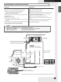
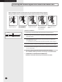
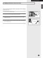
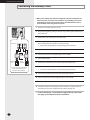
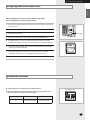
Series FRANÇAIS ESPAÑOL MHFNCA ENGLISH INSTALLATION MANUAL Free Joint Multi Air Conditioner (Cooling and Heating) E S F DB98-29163A(1) E-1 ENGLISH Contents PREPARING FOR INSTALLATION Safety Precautions . . . . . . . . . . . . . . . . . . . . . . . . . . . . . . . . . . . . . . . . . . . . . . . . . . 3 Choosing the Installation Location . . . . . . . . . . . . . . . . . . . . . . . . . . . . . . . . . . 5 Accessories . . . . . . . . . . . . . . . . . . . . . . . . . . . . . . . . . . . . . . . . . . . . . . . . . . . . . . . . . 6 INSTALLING THE AIR CONDITIONER Fixing the Installation Plate . . . . . . . . . . . . . . . . . . . . . . . . . . . . . . . . . . . . . . . . . 7 Purging the Indoor Unit . . . . . . . . . . . . . . . . . . . . . . . . . . . . . . . . . . . . . . . . . . . . 7 Installing and Connecting the Assembly Pipe of the Indoor Unit . . . . 8 Cutting or Extending the Pipe . . . . . . . . . . . . . . . . . . . . . . . . . . . . . . . . . . . . . . . 9 Installing and Connecting the Drain Hose of the Indoor Unit . . . . . . 10 Changing Direction of the Drain Hose . . . . . . . . . . . . . . . . . . . . . . . . . . . . . . 11 Connecting the Assembly Cable . . . . . . . . . . . . . . . . . . . . . . . . . . . . . . . . . . . 12 Assigning Address to Indoor Unit . . . . . . . . . . . . . . . . . . . . . . . . . . . . . . . . . . . 13 Additional Functions . . . . . . . . . . . . . . . . . . . . . . . . . . . . . . . . . . . . . . . . . . . . . . . . 13 COMPLETING THE INSTALLATION Fixing the Indoor Unit in Place . . . . . . . . . . . . . . . . . . . . . . . . . . . . . . . . . . . . . . 14 Final Check and Trial Operation . . . . . . . . . . . . . . . . . . . . . . . . . . . . . . . . . . . . . 15 Providing Information for User . . . . . . . . . . . . . . . . . . . . . . . . . . . . . . . . . . . . . . 16 E-2 ENGLISH Safety Precautions Keep this installation manual together with the user’s manual in a handy place so that you can find it whenever you need to see it after reading this manual thoroughly. Make sure to read the following safety precautions carefully before installation. Make sure to observe the cautions specified in this manual. Conduct a test run of the unit after installation and then explain all system functions to the owner. The indications and meanings are as shown below. WARNING This indicates the possibility of serious injury or death. Installation must be carried out by a qualified installer. Installers are required to read the general information carefully for safety. Do not put the unit near dangerous substances to prevent fire, explosion or injury and do not expose the unit to direct sunlight. Do not install the unit by yourself (owners). Incorrect installation of the unit could cause injury due to fire, electric shock and water leakage or from the unit falling. Consult a dealer or a qualified installer. Install the unit in a place where it is strong enough to hold the product weight. When installed in place where it is not strong enough to withhold the product weight, the unit could fall and cause injury. Use the specified wires to connect the indoor and outdoor units securely and attach the wires firmly to the terminal block connecting sections so that the pressure is not applied to the sections. Inappropriate connection and fixing could cause fire. Avoid the use of an extension cord and do not share the power outlet with other appliances. Incomplete connection, defective insulation or exceeding the permissible current may cause electric shock or fire. Make sure that the refrigerant gas does not leak after completing the installation. If the refrigerant gas of the indoor unit leaks and comes into contact with the fan heater, space heater or stove, harmful substances will be generated. Perform the installation securely referring to the installation manual. Incomplete installation could cause personal injury due to fire, electric shock and water leakage or from the unit falling. Attach the electrical cover to the indoor and outdoor unit securely. If not, it could result in fire or electric shock due to dust or water. Make sure to use the part provided or specified parts for the installation work. The use of defective parts could cause an injury or leakage of water due to a fire, an electric shock, the unit falling, etc. Make sure to turn off the main power when setting up the indoor unit electrical circuit or power cords. There is a risk of electric shock. The units must be installed according to distances declared, in order to permit accessibility from each side, either to guarantee correct operation of maintenance or repairing products. The unit’s parts must be reachable and removable completely under safety condition (for people or things) E-3 WARNING This indicates the possibility of serious injury or death. The unit should be installed in accordance with the National Electrical regulations. Ensure that the national safety code requirements have been followed for the main supply circuit. Ensure that a properly sized and connected ground wire is in place. CAUTION that may have taken place during transportation and do not install or use damaged equipment. All of the manufacturing and packaging material used for your new appliance are compatible with the environment and can be recycled. Dispose of the packaging material in accordance with the local requirements. conditioning system and contains a coolant that must be recovered and disposed of in an appropriate way by qualified personnel. At the end of the life cycle, take it to a proper recycling or disposal center or return it to the dealer so that it can be disposed correctly. E-4 frequency of the main power supply are those required for the unit to be installed and check the connection. Make sure that properly sized disconnecting and safety switches are installed. Do not attempt to repair, move, modify or reinstall the unit on your own. Make sure that these installations are carried out by qualified personnel to avoid electric shock or fire. Use the unit on a single outlet circuit. Do not share the power outlet with other appliances. Obtain the consent by a qualified installer before connecting the unit to the power supply system. This indicates the possibility of serious injury or damage to environments when operated incorrectly. Check the unit for damage This product is an air Check if the voltage and the Grounding the unit. Fasten a flare nut with a Do not install the unit in a To prevent injury when Do not connect the ground to a gas pipe, water pipe, lightning rod or telephone grounding. Defective grounding could cause electric shock. place where it is exposed to inflammable gas leakage. There is a risk of explosion. torque wrench as specified in this installation manual. When fastened too tight, a flare nut may break after a long period of time and cause refrigerant leakage. accidentally touching the indoor unit fan, install the indoor unit on a place higher than 2.5m. Install a ground leakage breaker depending on the installation place (where it is humid). If not, it may cause electric shock. Perform the drainage/piping work securely according to the installation manual. If not, water could drop from the unit and household goods could get wet and damaged. The air conditioner must be installed according to the national electrical regulations. The maximum input power & current is measured according to the IEC standard and the input power & current is measured according to the ISO and EN14511standard. PREPARING FOR INSTALLATION Indoor Unit Outdoor Unit Where airflow is not blocked Where cool air can be distributed throughout the room Install the refrigerant piping length and the height difference of both indoor and outdoor units as indicated in the installation diagram Wall that prevents vibration and is strong enough to hold the product weight Out of the direct sunlight 3.3ft or more away from the TV or radio (to prevent the screen from being distorted or noise from being generated) As far away as possible from fluorescent and incandescent lights (so that the remote control can be operated well) A place where the air filter can be replaced easily Where it is not exposed to strong wind Well ventilated and dustless places Out of the direct sunlight and rain Where neighbors are not annoyed by operation sound or hot air Solid wall or support that prevents vibration and is strong enough to hold the product weight Where there is no risk of flammable gas leakage When installing the unit at a high place be sure to fix the unit legs 9.9ft or more away from the TV or radio (to prevent the screen from being distorted or noise from being generated) Install the unit horizontally ENGLISH Choosing the Installation Location CAUTION Avoid the following places to prevent malfunction of the unit - Where there is machine oil - Where sulfide gas exists - Salty environment such as the seaside areas - Other special atmosphere areas Observe the clearances and maximum lengths as seen in the picture below when installing the air conditioner. 11.8 inch or more 4.9 inch or more 4.9 inch or more Wrap the refrigerant pipes and the drain hose with the absorbent pad and vinyl tape. Refer to page 15 for further details. You can select the direction of draining. (left or right) CAUTION: 9.9ft as minimum pipe length. It will reduce noise and vibration 23.6 inch minimum 11.8 inch minimum ‘H’ meters maximum total pipe Height ‘L’ meters maximum total pipe length A B C D 11.8 inch minimum Model L(ft) H(ft) 50 98.4 49.2 80 229.7 49.2 23.6 inch minimum Main power switch Make at least one round: It will reduce noise and vibration The appearance of the unit may be different from the diagram depending on the model. E-5 PREPARING FOR INSTALLATION Accessories The following accessories are supplied with the air conditioner: The number of each accessory is indicated in parentheses. Accessories in the Indoor Unit Case Installation Plate (1) Remote Control (1) Batteries for Remote Control (2) User’s Manual (1) Installation Manual (1) The following connection accessories are optional. If they are not supplied, you should obtain them before installing the air conditioner. 3-wire Power Cable Pipe Clamps A (3) E-6 2-wire Assembly Cable Assembly Pipe, Ø1/4inch (1) Pipe Clamps B (3) Assembly Pipe, Ø3/8inch (1) 26/35 Cement Nail (6) Assembly Pipe, Ø1/2inch (1) 52 M4 x 16 Tapped Screws (6) If these accessories are supplied, they will be in the accessory box. PE T3 Foam Tube Insulation (1) Drain Hose, length 6.56ft (1) Vinyl Tape (2) Putty 100g (1) INSTALLING THE AIR CONDTIONER ENGLISH Fixing the Installation Plate Before fixing the installation plate to the wall or window frame, you must determine the position of the 2.56inch hole through which the cable, pipe and hose pass to connect the indoor unit to the outdoor unit. When facing the wall, the pipe and cable can be connected from the: Right Left Underside (right) Rear (right or left) 2 If you fix the indoor unit to a... Follow step(s)... Wall 3. Window frame 4 to 6. Fix the installation plate to the wall giving attention to the weight of the indoor unit. If you mount the plate to a concrete wall with anchor bolts, the anchor bolts must not project more than 0.8inch(20mm). Pipe hole Ø2.56 inch (65mm) B 3 Determine the position of the pipe and drain hose hole as seen in the picture and drill the hole with an inner diameter of 2.56inch so that it slants slightly downwards. B 1 A 4 5 6 Determine the positions of the wooden uprights to be attached to the window frame. Attach the wooden uprights to the window frame giving attention to the weight of the indoor unit. Attach the installation plate to the wooden uprights using tapping screws as seen in the picture. A B C MH026FNCA MH035FNCA inch mm 4.72 120 1.06 27 2.68 68 C MH052FNCA inch 5.51 1.34 2.68 mm 140 34 68 Purging the Indoor Unit Upon delivery, there may be inert gas inside the indoor unit. Purge the gas from the indoor unit before connecting the assembly pipe. Unscrew the caps at the end of each pipe. Result: All inert gas exhausts from the indoor unit. To prevent dirt or foreign substances from getting into the pipes during installation, do NOT remove the caps completely until you are ready to connect the pipes. E-7 INSTALLING THE AIR CONDTIONER Installing and Connecting the Assembly Pipe of the Indoor Unit Connect indoor and outdoor units with field-supplied copper pipes by means of flare connections. Use insulated seamless refrigeration grade pipe only, (Cu DHP type according to ISO1337), degreased and deoxidized, suitable for operating pressures of at least 4200 kPa and for burst pressure of at least 20700 kPa. Under no circumstances must sanitary type copper pipe be used. There are 2 refrigerant pipes of different diameters: The smaller one is for the liquid refrigerant The larger one is for the gas refrigerant A short pipe is already fitted to the air conditioner. You may need to extend the pipe using the assembly pipe. (optional) A B C The connection procedure for the refrigerant pipe varies according to the exit position of the pipe when facing the wall: Right(A) Left(B) Underside(C) Rear 1 Cut out the appropriate knock-out piece on the rear of the indoor unit unless you connect the pipe directly from the rear. 2 Smooth the cut edges. 3 Remove the protection caps of the pipes and connect the assembly pipe to each pipe. Tighten the nuts first with your hands, and then with a torque wrench, applying the following torque: Outer Diameter 1/4 inch 3/8 inch 1/2 inch 5/8 inch Torque 10.1~12.3 ft.lb 18.1~20.3 ft.lb 27.5~30.4 ft.lb 31.8~34.7 ft.lb If you want to shorten or extend pipes, refer to page 9. 4 Cut off the remaining foam insulation. 5 If necessary, bend the pipe to fit along the bottom of the indoor unit. Then pull it out through the appropriate hole. The pipe should not project from the rear of the indoor unit. The bending radius should be 4 inch or more. 6 Pass the pipe through the hole in the wall. 7 For further details on how to connect to the outdoor unit and purge the air, refer to page 13. The pipe will be insulated and fixed permanently into position after finishing the installation and the gas leak test; refer to page 14 for further details. DO NOT WALL UP THE PIPE CONNECTION ! All refrigerant pipe connection must be easy accessible and serviceable. E-8 INSTALLING THE AIR CONDTIONER Cutting or Extending the Pipe ENGLISH A 24.6ft pipe is supplied with the air conditioner. (optional) The length of the pipe can be: Extended up to 49.2 ft Shortened as required 1 Make sure that you have the required tools (pipe cutter, reamer, flaring tool and pipe holder.) 2 If you want to shorten the pipe, cut it using a pipe cutter, ensuring that the cut edge remains at 90° with the side of the pipe (see examples of correctly and incorrectly cut edges below.) Oblique Rough Burr 3 To prevent a gas leak, remove all burrs at the cut edge of the pipe using a reamer. 4 Put a flare nut slightly into the pipe and modify the flare. Outer Diameter (D) 1/4 inch 3/8 inch 1/2 inch 5/8 inch 5 Damaged Surface Cracked Uneven Thickness Align the pipes to connect them easily. Tighten the flare nuts first with your hands, and then with a torque wrench, applying the following torque: Outer Diameter 1/4 inch 3/8 inch 1/2 inch 5/8 inch 7 0.05 inch 0.07 inch 0.08 inch 0.09 inch Check if you flared the pipe correctly (see examples of incorrectly flared pipes below.) Inclined 6 Depth (A) Torque 10.1~12.3 ft.lb 18.1~20.3 ft.lb 27.5~30.4 ft.lb 31.8~34.7 ft.lb For further details on how to connect to the outdoor unit and purge the air, refer to page 13. In case welding the pipe, the gas nitrogen must be blown into the parts. E-9 INSTALLING THE AIR CONDTIONER Installing and Connecting the Drain Hose of the Indoor Unit When installing the drain hose for the indoor unit, check if condensation draining is adequate. When passing the drain hose through the2.56 inch hole drilled in the wall, check the following: 5cm less Ditch The hose must NOT slant upwards. The end of the drain hose must NOT be placed under water. Do NOT bend the hose in different directions. Keep a clearance of at least 2 inch between the end of the hose and the ground. Do NOT place the end of the drain hose in a hollow. Drain hose installation: Shield Drain hose 1 If necessary, connect the 6.6ft extension drain hose to the drain hose. 2 If you use the extension drain hose, insulate the inside of the extension drain hose with a shield. 3 Fit the drain hose into 1 of 2 drain hose holes, then fix the end of the drain hose tightly with a clamp. Extension drain hose If you don’t use the other drain hose hole, block it with a rubber stopper. 4 Pass the drain hose under the refrigerant pipe, keeping the drain hose tight. 5 Pass the drain hose through the hole in the wall. Check if it slants downwards as seen in the picture. The hose will be fixed permanently into position after finishing the installation and the gas leak test; refer to page 14 for further details. DO NOT WALL UP THE DRAIN HOSE CONNECTION ! Drain hose connection must be easy accessible and serviceable. E-10 INSTALLING THE AIR CONDTIONER ENGLISH Changing Direction of the Drain Hose You can select the direction of the drain hose, depending on where you want to install the indoor unit. 1 Detach the rubber cap with the flyer. Screw hole 2 Screw Detach the drain hose by pulling it and turning to the left. Drain hose 3 Insert the drain hose by fixing it into the groove of the drain hose and the outlet of the drain pan. 4 Attach the rubber cap with a screwdriver by turning it to the right until it fixes to the end of the groove. Drain pan outlet Rubber cap E-11 INSTALLING THE AIR CONDTIONER Connecting the Assembly Cable When you install the unit, make first refrigerant connections and then electrical connections.Connect the air conditioner to grounding system before performing the electrical connection.If unit is uninstalled first disconnect electrical cables, then refrigerant connections. 1 Extend the assembly cable if necessary. 2 Open the front grille by pulling on the tabs on the lower right and left sides of the indoor unit. 3 Remove the screw securing the connector cover. 4 Pass the assembly cable through the rear of the indoor unit and connect the assembly cable to terminals as seen in the picture. Indoor unit 1(L) 2(N) 1 F1 2 5 Pass the other end of the cable through the 2.56inch hole in the wall. 6 Close the connector cover, tightening the screw carefully. F1 F2 7 Close the front grille. F1 F2 8 Remove the terminal board cover on the side of the outdoor unit. 9 Connect the cables to the terminals as seen in the picture. F1 F2 Earth terminal 1 Outdoor unit 2 1(L) 2(N) Each wire is labeled with the corresponding terminal number. F2 Earth terminal Screws on terminal block must not be unscrewed with the torque less than 0.87 ft•lb. Each wire is labeled with the corresponding terminal number. 10 Connect the grounding conductor to the grounding terminals. 11 Close the terminal board cover, tightening the screw carefully. 12 Connect the power cable to the indoor unit. 13 For further details on how to plug the other end of the assembly cable into the outdoor unit, refer to installation manual of the outdoor unit. In Russia and Europe, consult with the supply authority to determine the supply system impedance before installation. E-12 INSTALLING THE AIR CONDTIONER ENGLISH Assigning Address to Indoor Unit Before installing the indoor unit, assign an address to the indoor unit according to the air conditioning system plan. 1 Open the front grille by pulling on the tabs on the lower right and left sides of the indoor unit. 2 Remove the screw securing the cover PCB. 3 Remove the cover PCB. 4 The address of the indoor unit is assigned by adjusting MAIN(SW02). 5 The MAIN address is for communication between the indoor unit and the outdoor unit. Therefore, you must set it to operate the air conditioner properly. 6 It is required to set the RMC address if you install the wired remote controller and/or the centralized controller. 7 If you install optional accessories such as the wired remote controller, centralized controller, etc. see an appropriate installation manual. 8 Cover PCB SW02 MAIN Refer to the outdoor unit installation manual for the details. Additional Functions Compensation for lost temperature in heating operation K5 K6 K7 K8 Reduces the difference between an actual room temperature and a sensed temperature by the air conditioner when heating. Switch No. Switch ON Switch OFF K5 3.6°F compensation 9°F compensation SW06 E-13 COMPLETING THE INSTALLATION Fixing the Indoor Unit in Place After checking for gas leaks in the system, insulate the pipe, hose and cables. Then place the indoor unit on the installation plate. 1 To avoid condensation problems, place heat-resistant polyethylene foam separately around each refrigerant pipe in the lower part of the indoor unit. 2 Wrap the refrigerant pipe and the drain hose in the rear of the indoor unit with the absorbent pad. Wind the pipe and hose three times to the end of the indoor unit with the absorbent pad. (0.79inch interval) 3 Wind the pipe, assembly cable and drain hose with insulation tape. 4 Place the bundle (the pipe, assembly cable and drain hose) in the lower part of the indoor unit carefully so it doesn’t project from the rear of the indoor unit. 5 Hook the indoor unit to the installation plate and move the unit to the right and left until it is securely in place. 6 Wrap the rest of the pipe with vinyl tape. 7 Attach the pipe to the wall using clamps (optional). Installation plate E-14 COMPLETING THE INSTALLATION ENGLISH Final Check and Trial Operation To complete the installation, perform the following checks and tests to ensure that the air conditioner operates correctly. 1 Check the following: Strength of the installation site Tightness of pipe connection to detect gas leak Electric wiring connection Heat-resistant insulation of the pipe Drainage Grounding conductor connection Correct operation (follow the steps below) 2 Press the button and check the following: The indicator on the indoor unit lights up. The airflow blade opens and the fan gears up for operation. 3 Press any button and check the following: The appropriate indicator lights up and the air conditioner operates according to the selected mode or function. 4 Press the button and check the following: The airflow blades work properly. E-15 Providing Information for User After finishing the installation of the air conditioner, explain the following to the user: (refer to appropriate pages in the User’s Manual.) 1 How to start and stop the air conditioner 2 How to select the modes and functions 3 How to adjust the temperature and fan speed 4 How to adjust the airflow direction 5 How to set the timers 6 How to clean and replace the filters When you complete the installation successfully, hand over the User’s Manual and this Installation Manual to the user for storage in a handy and safe place. E-16