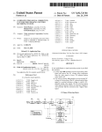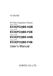
1
PC-HELPER
PCI Bus Expansion Chassis
Short size, 2-Slots, BLACK
ECH-PCI-CE-H2C
User’s Manual
CONTEC CO.,LTD.
Check Your Package
Thank you for purchasing the CONTEC product.
The product consists of the items listed below.
Check, with the following list, that your package is complete.
items, contact your retailer
If you discover damaged or missing
Product Configuration List
- Expansion chassis…1
- Power connector …1
[ECH-PCI-CE-H2C]
- This User’s Manual (this booklet) …1
- Contact…4
- Slot cover …1
- Rubber feet …4
- Bracket …2
- Bracket fixed screw …8
- Body fixed screw …4
- Board fixed screw …2
ECH-PCI-CE-H2C
i
Copyright
Copyright 2011 CONTEC CO., LTD.
ALL RIGHTS RESERVED.
No part of this document may be copied or reproduced in any form by any means without prior written
consent of CONTEC CO., LTD.
CONTEC CO., LTD. makes no commitment to update or keep current the information contained in
this document.
The information in this document is subject to change without notice.
All relevant issues have been considered in the preparation of this document.
Should you notice an
omission or any questionable item in this document, please feel free to notify CONTEC CO., LTD.
Regardless of the foregoing statement, CONTEC assumes no responsibility for any errors that may
appear in this document or for results obtained by the user as a result of using this product.
Trademarks
MS, Microsoft, Windows and Windows NT are trademarks of Microsoft Corporation.
product names are trademarks of their respective holder.
ii
Other brand and
ECH-PCI-CE-H2C
Table of Contents
Check Your Package ................................................................................................................................ i
Copyright .................................................................................................................................................ii
Trademarks ..............................................................................................................................................ii
Table of Contents ...................................................................................................................................iii
1
BEFORE USING THE PRODUCT
1
About the Chassis.................................................................................................................................... 1
Features............................................................................................................................................. 1
Expansion adapter (Option)............................................................................................................. 2
Combinations of Expansion Adapters and Expansion Chassis ...................................................... 2
Accessory (Option) .......................................................................................................................... 2
Restrictions....................................................................................................................................... 3
Customer Support.................................................................................................................................... 4
Web Site ........................................................................................................................................... 4
Limited One-Year Warranty ................................................................................................................... 4
How to Obtain Service............................................................................................................................ 4
Liability ................................................................................................................................................... 4
Safety Precautions ................................................................................................................................... 5
Safety Information ........................................................................................................................... 5
Handling Precautions ....................................................................................................................... 5
Environment ..................................................................................................................................... 7
Inspection ......................................................................................................................................... 7
Storage.............................................................................................................................................. 7
Disposal ............................................................................................................................................ 7
2
SETUP
9
What is Setup?......................................................................................................................................... 9
Step 1 Preparation ................................................................................................................................. 10
Items to be prepared....................................................................................................................... 10
Names of major parts ..................................................................................................................... 11
DC Power Input Connector : DC-IN ............................................................................................. 11
Step 2 Setting up the hardware ............................................................................................................. 12
Attaching the Brackets................................................................................................................... 12
Attaching the FG ............................................................................................................................ 12
Attaching the Fan (Option)............................................................................................................ 13
Installation Orientation .................................................................................................................. 14
Step 3 Installing the Expansion Board ................................................................................................. 15
Step 4 Connecting the Cable................................................................................................................. 16
Connecting the connection cable to the Expansion Adapter ........................................................ 16
ECH-PCI-CE-H2C
iii
Connecting the connection cable to this product ..........................................................................16
Connecting the AC adapter ............................................................................................................16
Plugging the AC Power Cable .......................................................................................................17
Step 5 Installing the expansion adapter board ......................................................................................18
Step 6 Setup and Check.........................................................................................................................18
Starting the system .........................................................................................................................18
Setting up the hardware in Windows.............................................................................................19
Checking the hardware in Windows ..............................................................................................19
Connecting the CX100n ........................................................................................................................20
Connectting the CX100n ................................................................................................................20
Installation Requirements...............................................................................................................21
Setup Troubleshooting...........................................................................................................................22
Symptoms and Actions...................................................................................................................22
3
ABOUT HARDWARE
23
Hardware specification ..........................................................................................................................23
Physical Dimensions..............................................................................................................................25
iv
ECH-PCI-CE-H2C
1. Before Using the Product
1 Before Using the Product
This chapter provides information you should know before using the product.
About the Chassis
This product is an expansion chassis that adds PCI bus slots to a PC. It can add PCI bus slots by
connecting an optional expansion adapter (EAD-CE-LPE, EAD-CE-EC). The board that can be
mounted is short-type [176.5 (L) x 107 (H) mm] PCI boards.
Features
- PCI bus (5V/32bit 33MHz) slots can be added to your PC.
Two PCI bus (5V/32bit 33MHz) slots can be added.
ECH-PCI-CE-H2C adds two PCI bus slots.
This expansion chassis is connected to a PC using an optional expansion adapter.
- Short-type PCI bus boards can be connected. (ECH-PCI-CE-H2C)
You can connect two short-type [176.5 (L) x 107 (H) mm] PCI boards.
ECH-PCI-CE-H2C can be connected two PCI Boards.
- The best case size design matched to CX100n and the BX100n series.
The design is not ruined by designing the case size matched to CX100n and the BX100n series.
- The cTEST controller realizes further Extensions
Be accessible in cTEST controller CX100n (or BOX computer BX100n) and cable assembly.
Can use it in unification and separate by installing attached insulator bracket.
- A wide range of power supplies (10.8 - 31.2VDC) supported
As the product supports a wide range of power (10.8 - 31.2VDC), it can be used in a variety of power
environments.
- The cooler fan can be installed according to the usage.
The cooler fan can be installed according to the usage.
ECH-PCI-CE-H2C
1
1. Before Using the Product
Expansion adapter (Option)
Expansion Adapter for Express Card Slot
Expansion Adapter for PCI Express Slot
:
:
EAD-CE-EC
EAD-CE-LPE
Check the CONTEC’s Web site for more information on these expansion adapters.
Combinations of Expansion Adapters and Expansion Chassis
The expansion adapters and expansion chassis can be used in the following combinations:
Expansion chassis ECH-PCI-CE
Expansion
adapter
-H2B
-H2C
-F2B
-H4B
-F4B
-H4A
-H7A
EAD-CE-EC
Ο
Ο
Ο
Ο
Ο
Ο
x
-H13A
x
EAD-CE-LPE
Ο
Ο
Ο
Ο
Ο
Ο
Ο
Ο
Expansion Chassis
ECH-PCI-CE-H2B
ECH-PCI-CE-H2C
ECH-PCI-CE-H4A
ECH-PCI-CE-H7A
ECH-PCI-CE-F2B
ECH-PCI-CE-H4B
ECH-PCI-CE-F4B
ECH-PCI-CE-H13A
Expansion Adapter
EAD-CE-EC
EAD-CE-LPE
Accessory (Option)
AC adapter
: IPC-ACAP12-04
PCI Express Cable (1m)*
: CB-CE-1
PCI Express Cable (3m)*
: CB-CE-3
Fan 41x12
: FAN0412
*Need for connect to CX100n, BX100n.
2
ECH-PCI-CE-H2C
1. Before Using the Product
Restrictions
This product is used in a combination with the optional expansion adapter. The following restrictions
apply to the situation when the expansion adapter is connected to the expansion chassis.
This product has restrictions on the types of PCs and boards that can be used.
Be sure to check the following restrictions before use.
< Restrictions of PC>
This product uses the PCI-to-PCI Bridge to extend the bus.
The PCI boards plugged in PCI slots in this product are recognized if the PCI-to-PCI bridge is
recognized by the BIOS in the PC used. Ask the PC vendor for whether the BIOS recognizes the
PCI-to-PCI bridge.
< Restrictions on transfer rate >
When the expansion chassis accommodates a board that performs high-speed transfer such as bus
mastering, the overall transfer rate may be lower than that of PCI bus slots in the main unit of a desktop
PC.
This is caused by bus extension by the PCI-to-PCI Bridge.
The transfer rate may vary with the system configuration and the type of the PC.
< Restrictions of PCI board>
None of the following boards can be plugged into any expansion slot in this product.
-
Video display board (VGA board)
-
Board to connect a PCI bus expansion chassis
-
Board explicitly stated not to be used with the PCI-to-PCI Bridge
-
Some boards, even PCI-compliant ones, may not work depending on their specifications
ECH-PCI-CE-H2C
3
1. Before Using the Product
Customer Support
CONTEC provides the following support services for you to use CONTEC products more efficiently
and comfortably.
Web Site
Japanese
English
Chinese
http://www.contec.co.jp/
http://www.contec.com/
http://www.contec.com.cn/
Latest product information
CONTEC provides up-to-date information on products.
CONTEC also provides product manuals and various technical documents in the PDF.
Free download
You can download updated driver software and differential files as well as sample programs available in
several languages.
Note!
For product information
Contact your retailer if you have any technical question about a CONTEC product or need its price,
delivery time, or estimate information.
Limited One-Year Warranty
CONTEC products are warranted by CONTEC CO., LTD. to be free from defects in material and
workmanship for up to one year from the date of purchase by the original purchaser.
Repair will be free of charge only when this device is returned freight prepaid with a copy of the
original invoice and a Return Merchandise Authorization to the distributor or the CONTEC group office,
from which it was purchased.
This warranty is not applicable for scratches or normal wear, but only for the electronic circuitry and
original products. The warranty is not applicable if the device has been tampered with or damaged
through abuse, mistreatment, neglect, or unreasonable use, or if the original invoice is not included, in
which case repairs will be considered beyond the warranty policy.
How to Obtain Service
For replacement or repair, return the device freight prepaid, with a copy of the original invoice. Please
obtain a Return Merchandise Authorization number (RMA) from the CONTEC group office where you
purchased before returning any product.
*
No product will be accepted by CONTEC group without the RMA number.
Liability
The obligation of the warrantor is solely to repair or replace the product. In no event will the
warrantor be liable for any incidental or consequential damages due to such defect or consequences that
arise from Safety Precautions.
Understand the following definitions and precautions to use the product safely.
4
ECH-PCI-CE-H2C
1. Before Using the Product
Safety Precautions
Understand the following definitions and precautions to use the product safely.
Safety Information
This document provides safety information using the following symbols to prevent accidents resulting
in injury or death and the destruction of equipment and resources. Understand the meanings of these
labels to operate the equipment safely.
DANGER
DANGER indicates an imminently hazardous situation which, if not avoided, will
result in death or serious injury.
WARNING
WARNING indicates a potentially hazardous situation which, if not avoided, could
result in death or serious injury.
CAUTION
CAUTION indicates a potentially hazardous situation which, if not avoided, may
result in minor or moderate injury or in property damage.
Handling Precautions
DANGER
Do not use the product where it is exposed to flammable or corrosive gas.
an explosion, fire, electric shock, or failure.
Doing so may result in
CAUTION
-
Do not plug or unplug any board into or from an expansion slot with the PC or
this product powered.
Doing so may result in a malfunction, overheating, or fault.
Be sure to turn off the PC or this product and unplug their power cables before plugging or
unplugging any expansion board.
-
Do not plug or unplug the cable interconnecting the PC and the expansion chassis with the PC or
this product powered.
-
Do not turn on or off the power switch of this product with the PC powered.
in a malfunction.
-
The total current consumption by the boards installed in the expansion slots in this product must not
exceed the maximum power capacity of its power supply.
Failure to supply ample power to expansion boards could result in a malfunction, overheating, or
fault.
-
The external supply voltage or drive current must not exceed the rating.
-
Do not connect any signal other than specified to the on-board connector.
Doing so may result in a malfunction, overheating, fault, or damage.
-
When plugging or unplugging the power connector, be sure to hold it by the connector itself.
ECH-PCI-CE-H2C
Doing so may result
5
1. Before Using the Product
-
Since the expansion chassis is a precision device, do not store or use it where it is subject to shock
or vibration. Also avoid any place where the chassis is exposed to direct sunlight, extremely high
humidity, or much dust.
-
Do not use or store the chassis where it is exposed to any chemical either directly or as vapor in the
air.
-
The chassis has ventilating slits to prevent it from overheating.
ventilating slits blocked or in an ill-ventilated place.
-
Do not use the chassis near equipment generating a strong magnetic field or noise.
Doing so may result in a malfunction, overheating, fault, or damage in the chassis, your PC, or
both.
-
It is very dangerous to use the chassis with water, liquid, or metal (conductive) chips left inside.
Be careful not to let such foreign matters in the chassis.
-
The specifications of this product are subject to change without notice for enhancement or quality
improvement.
Even when using the product continuously, be sure to read the manual and understand the contents.
-
Do not modify this product.
CONTEC will bear no responsibility for any problems, etc., resulting from modifying the product.
-
Regardless of the foregoing statements, CONTEC is not liable for any damages whatsoever
(including damages for loss of business profits) arising out of the use of or inability to use this
CONTEC product or the information contained herein.
Avoid using the chassis with the
FCC PART 15 Class A Notice
NOTE
This equipment has been tested and found to comply with the limits for a Class A digital device,
pursuant to part 15 of the FCC Rules. These limits are designed to provide reasonable protection
against harmful interference when the equipment is operated in commercial environment.
This equipment generates, uses, and can radiate radio frequency energy and, if not installed and
used in accordance with the instruction manual, may cause harmful interference to radio
communications. Operation of this equipment in a residential area is likely to cause harmful
interference at his own expense.
WARNING TO USER
Change or modifications not expressly approved the manufacturer can void the user's authority to
operate this equipment.
6
ECH-PCI-CE-H2C
1. Before Using the Product
Environment
Use this product in the following environment.
may overheat, malfunction, or cause a failure.
If used in an unauthorized environment, the chassis
Operating temperature
0 - 50°C
Humidity
20 - 80%RH (No condensation)
Corrosive gases
None
Floating dust particles
Not to be excessive
Inspection
Inspect the product periodically as follows to use it safely.
Storage
When storing this product, keep it in its original packing form.
(1) Wrap it in the packing material, and then put it in the box.
(2) Store the package at room temperature at a place free from direct sunlight, moisture, shock,
vibration, magnetism, and static electricity.
Disposal
When disposing of the product, follow the disposal procedures stipulated under the relevant laws and
municipal ordinances.
ECH-PCI-CE-H2C
7
1. Before Using the Product
8
ECH-PCI-CE-H2C
2. Setup
2 Setup
This chapter explains how to set up the chassis.
Refer to the user’s manual for the expansion adapter EAD-CE-LPE, EAD-CE-EC as required.
What is Setup?
Setup means a series of steps to take before the product can be used.
Taking the following steps in this chapter sets up the ECH-PCI-CE-H2B.
Step 1 Preparation
Step 2 Setup the Hardware
Step 3 Installing the Expansion Board
Step 4 Connecting the Cable
Step 5 Installing the expansion adapter board
Step 6 Setup and Check
If setup fails to be performed correctly, refer to “Setup Troubleshooting”.
ECH-PCI-CE-H2C
9
2. Setup
Step 1 Preparation
Configuration image
The photo is of the EAD-CE-EC+ECH-PCI-CE-H2C
Figure 2.1. Configuration image
Items to be prepared
-
PC
-
Expansion adapter
Expansion adapter card…(a),
Connection Cable …(b)
-
Expansion chassis
This product(Chassis)…(c)
AC adapter…(d)
-
[Picture is ECH-PCI-CE-H2C.]
PCI board to be installed
(c)
(d)
(b)
10
(a)
ECH-PCI-CE-H2C
2. Setup
Names of major parts
ECH-PCI-CE-H2B/F2B
Front view
Back view
Figure 2.2. Names of major parts < ECH-PCI-CE-H2C >
DC Power Input Connector : DC-IN
To supply the power, always use the power supply listed below.
Rated input voltage
: 12 - 24VDC
Range of input voltage : 10.8 - 31.2VDC
Power capacity
: 12V 4.0A or more, 24V 1.9A or more
Table 2.1. DC Power Connector
Connector type
9360-04P (mfd. by ALEX)
Pin No.
4
3
2
1
Signal name
1
GND
2
GND
3
12 - 24V
4
12 - 24V
Applicable connector on the connector side
Housing
Contact
: 9357-04 (mfd. by ALEX) or 5557-04R (mfd. by MOLEX)
: 4256T2-LF (AWG18-24) (mfd. by ALEX) or 5556 (AWG18-24) (mfd. by MOLEX)
Rise time of power supply
Figure 2.3. Graph of Rise Time of Power Supply
ECH-PCI-CE-H2C
11
2. Setup
Step 2 Setting up the hardware
-
Before you start, be sure that the power is turned off.
Remove only those screws that are explained. Do not move any other screw.
Attaching the Brackets
The brackets can be used in two ways as illustrated below. ECH-PCI-CE-H2C using the brackets by the
appropriate method suitable for the operating environment.
(1) Use screws to attach the bundled attachment fittings with a screw.
Do not tighten screws with excess force.
Figure 2.4.
Attaching the Brackets
CAUTION
Screw holes may be damaged if screws are tightened with a torque greater than the specified torque.
The specified tightening torque is 5 - 6kgf⋅cm.
Attaching the FG
(1) Use screws to attach the FG.
Figure 2.5.
12
Attaching the FG
ECH-PCI-CE-H2C
2. Setup
Attaching the Fan (Option)
Refer to the user’s manual for the cooler fan FAN0412 to install its brackets to the expansion chassis.
Figure 2.6. Attaching the Fan (Option)
CN2 specification
Table 2.1.
Power Connector(CN2) for Cooler Fan
5045-02A (mfd. by ALEX)
Pin No.
Signal name
1
+12V
2
GND
*Equivalent types are also available.
Applicable connector on the connector side
Housing
Contact
: 50802-8100 (mfd. by MOLEX)
: 51191-0200 (mfd. by MOLEX)
*Equivalent types are also available.
ECH-PCI-CE-H2C
13
2. Setup
Installation Orientation
-ECH-PCI-CE-H2C
< Vertically placed >
< Horizontally placed >
Figure 2.7. Installation Orientation
< ECH-PCI-CE-H2C >
-ECH-PCI-CE-H2C + CX100n
< Horizontally placed >
Figure 2.8. Installation Orientation
14
<ECH-PCI-CE-H2C + CX100n >
ECH-PCI-CE-H2C
2. Setup
Step 3 Installing the Expansion Board
CAUTION
Before installing an expansion board on this product, be sure to turn off your PC or this product and
unplug the AC power cables from wall outlets.
Follow the procedure below to install the expansion board on this product.
(1) Unplug the Power connector and Connection Cable from this product.
(2) Remove six screwes from the side panel, then remove the chassis cover.
Figure 2.9.
Removing the cover
Figure 2.10. Installing the Expansion Board
(3) Plug the expansion board into a PCI slot and fasten the brackets with the attached screw.
fasten the bundled attachment fittings with a screw.
Apply
Slot covers to unused slots and fasten them with screws.
(4) Put the chassis cover back in place and fasten it with the removed screws.
ECH-PCI-CE-H2C
15
2. Setup
Step 4 Connecting the Cable
Connecting the connection cable to the Expansion Adapter
Refer to the user’s manual for the expansion adapter EAD-CE-LPE, EAD-CE-EC to connect its
connection cable to the expansion adapter.
Connecting the connection cable to this product
Connect the connector of the connection cable to the connector of this product.
Picture is ECH-PCI-CE-H2C.
Figure 2.11. Connecting the connection cable to this product
CAUTION
Do not plug the connection cable into any other connector as doing so can cause a fault.
Connecting the AC adapter
(1) Connect the Power connector to this product.
Picture is ECH-PCI-CE-H2C.
Figure 2.12. Connecting the Power connector of AC adapter
(2) Plug the AC power cable into the AC adapter.
(3) Plug the AC power cable into a wall outlet.
*
This product has no power switch.
CAUTION
Do not connect the Power connector to this product after plugging the AC power cable into the wall
outlet, or the expansion chassis may cause a fault.
Connect the AC adapter to this product first, then plug the AC power cable into the wall outlet.
16
ECH-PCI-CE-H2C
2. Setup
Plugging the AC Power Cable
(1) Please pull the AC power cable out of the wall power outlet.
(2) Please confirm the led on the front panel of expansion chassises is turned off.
(3) Please pull out the AC power cable from AC adaptor.
(4) Please pull out the Power connector from chassis.
CAUTION
Do not pull out the Power connector from chassis whenAC power cable is still connecting to the
wall power outlet. This may cause product malfunction. Please pull out the Power connector from
the chassis after unplugging AC power cable from the wall power outlet.
ECH-PCI-CE-H2C
17
2. Setup
Step 5 Installing the expansion adapter board
Refer to the user’s manual for the expansion adapter EAD-CE-LPE, EAD-CE-EC to install the
expansion bus adapter on the PC.
Step 6 Setup and Check
Starting the system
This product is turned on and off in power supply.
Turning on the system
(1) Connect the Power connector to this product.
(2) Plug the AC power cable into a wall outlet.
(3) Make sure that the POWER LED on this product is on.
(4) The power supply of a PC is turned ON.
Turning off the system
(1) The power supply of a PC is turned OFF.
(2) Pull the AC power cable out of the wall power outlet.
(3) Pull out the AC power cable from AC adaptor.
(4) Pull out the Power connector from chassis.
CAUTION
Do not turn on or off this product with the PC main unit powered.
Doing so cancels the detection of the bus adapter. When turning this product on back, restart the
PC main unit.
18
ECH-PCI-CE-H2C
2. Setup
Setting up the hardware in Windows
At startup of Windows, the PCI-to-PCI Bridge used by this product are detected in sequence and
identified automatically by the Windows standard driver.
After that, the PCI boards installed on this product are detected in sequence.
For setting up and checking the boards used on the expansion chassis, refer to their respective manuals.
Checking the hardware in Windows
You can use Device Manager to check whether this product has been identified in Windows.
Manager shows “PCI standard PCI-to-PCI bridge” under “System devices”.
Device
Figure 2.13. Sample screen shot of Device Manager
ECH-PCI-CE-H2C
19
2. Setup
Connecting the CX100n
Connectting the CX100n
(1) Remove four screws (ECH-PCI-CE-H2C, CX100n).
Figure 2.14. Removing the screws (CX100n)
(2) Fasten the Brackets with attached Brackets fixed screwes.
Figure 2.15. Attaching the Brackets
20
ECH-PCI-CE-H2C
2. Setup
Installation Requirements
Be sure that the ambient temperature is within the range specified in the installation environment
requirement by making space between the product and device that generates heat or exhaust air.
Distances between this product and its vicinity
CAUTION
-
When using this chassis connected with CX100n, keep it at least 20mm away from any object such
as the wall for cooling purposes.
-
Attaching rubber feet to the chassis makes it 3.6mm taller.
-
ECH-PCI-CE-H2C connected with CX100n
Figure 2.16. Distances between this product and its vicinity. < ECH-PCI-CE-H2C + CX100n >
CAUTION
Do not install this product into the fully-sealed space except the case in which the internal
temperature is adjustable by equipment such as air conditioner. Troubles such as operational
malfunctions could be occurred by the temperature increase caused by long-term usage.
ECH-PCI-CE-H2C
21
2. Setup
Setup Troubleshooting
Please confirm followings when the ECH-PCI-CE-H2C does not work.
Symptoms and Actions
The chassis won’t be turned on.
a.
Make sure that the Power connector has been connected correctly.
b.
Make sure that the AC power cable has been connected correctly.
c.
Make sure that the power supplies of the PC or this product are on.
d.
Make sure that you have followed the procedure in Chapter 2.
e.
Even though the chassis is still not turned on, check whether it is turned on with no board installed.
If the chassis is turned on with no board installed, check the total current consumption by the
installed boards. The total current consumption must not exceed the power capacity of this
product.
No PCI board on this product is detected.
f.
Make sure that the expansion adapter has been installed correctly.
g.
Make sure that the connection cable has been installed correctly. When connecting the connection
cable to the main chassis, insert the connector until it clicks into place.
h.
Make sure that the POWER LED on this product is turned on.
b
g
f
a,c,h
The photo is of the EAD-CE-EC + ECH-PCI-CE-H2C. + IPC-ACAP12-04
22
ECH-PCI-CE-H2C
3. About Hardware
3 About Hardware
Hardware specification
Table 3.1.
Specification
Item
ECH-PCI-CE-H2C
Compatible bus
PCI Local Bus Specification Rev2.3 (+5Vtype)
Address space
32bit memory address, I/O address
Interrupt level
INTA - INTD
Bus operating clock
33MHz (Max.)
Number of user-available
2 slots
slots
(short size)
Acceptable board sizes (mm)
176.5(L) x 107(H)
Power supply
Expansion slot supplied
(The output current
+5VDC
+3.3VDC
+12VDC
5A (Max.)
2A (Max.)
1A (Max.)
must not exceed the
-12VDC
0.3A (Max.)
power
value on the right.)
Maximum total power
48W
capacity
Rated input voltage
12 - 24VDC
Range of input voltage
10.8-31.2VDC
Power consumption
12V 4.0A(Max.), 24V 2.0A(Max.)
Outside dimensions(mm)
270.0(W) x 182.0(H) x 50.0(L)
Weight
3.5 kg
(without rubber feet)
Outside dimensions of acceptable board (Max.)
< ECH-PCI-CE-H2C >
107(H)
176.5(L)
[mm]
ECH-PCI-CE-H2C
23
3. About Hardware
Table 3.2.
Environmental specification
Item
Specification
Operating temperature
0 - 50ºC
Operating humidity
20 - 80%RH(No condensation)
Storage temperature
0 - 60ºC
Storage humidity
10 - 90%RH(No condensation)
Floating dust particles
Not to be excessive
Corrosive gases
None
Line noise
AC line / ±2kV
Signal line / ±1kV (IEC61000-4-4 Level 3,EN61000-4-4 Level 3)
Line-noise
resistance
Static electricity
resistance*1
Contact discharge / ±2kV (IEC61000-4-2 Level 1, EN61000-4-2 Level1
Atmospheric discharge / ±4kV (IEC61000-4-2 Level 2, EN61000-4-2
Level 2)
Vibration
Sweep
10 - 57Hz / semi-amplitude 0.075 mm, 57 - 150Hz/1.0G
resistance
resistance*1
40 min. each in x, y, and z directions
(JIS C60068-2-6-compliant,
IEC60068-2-6-compliant)
Impact resistance
10G, half-sine shock for 11 ms in x, y, and z directions
(JIS C60068-2-27-compliant, IEC60068-2-27-compliant)
Grounding
Class D grounding (previous class 3 grounding), SG-FG / continuity
*1: It is provided with “PCI Express® External Cabling Specification”.
CAUTION
-
If you use this product in a noisy environment, the ferrite core must be installed in the PCI Express
cable at a position near the main body of this product side connector and in the AC cable at a
position near the plug of AC Adapter. For the type of ferrite core, refer to the following table
(Equivalent types are also available.)
Name
Maker
Turn
FRC2009A-6 or E04SR200935A
CONTEC or SEIWA
1~2
When attaching a ferrite core to the cable, coil it around 0-1 times near the connector while leaving
it open, and then close it.
PCI Express cable [Turn :1] x 2pcs
24
AC power cable [Turn :2] x 1pc
ECH-PCI-CE-H2C
3. About Hardware
Physical Dimensions
Figure 3.1. Outside Dimensions < ECH-PCI-CE-H2C
Vertically placed >
* When you fasten the bundled brackets to be fixed to the body, you should use the attached screws (M4 x 10).
Figure 3.2. Outside Dimensions < ECH-PCI-CE-H2C
Horizontally placed >
* When you fasten the bundled brackets to be fixed to the body, you should use the attached screws (M4 x 10).
ECH-PCI-CE-H2C
25
3. About Hardware
CAUTION
When using this chassis, keep it at least 20mm away from any object such as the wall for cooling
purposes.
Figure 3.3. Outside Dimensions < ECH-PCI-CE-H2C + CX100n >
CAUTION
When using this chassis, keep it at least 20mm away from any object such as the wall for cooling
purposes.
26
ECH-PCI-CE-H2C
ECH-PCI-CE-H2C
User’s Manual
CONTEC CO., LTD.
September 2011 Edition
3-9-31, Himesato, Nishiyodogawa-ku, Osaka 555-0025, Japan
Japanese http://www.contec.co.jp/
English http://www.contec.com/
Chinese http://www.contec.com.cn/
No part of this document may be copied or reproduced in any form by any means without prior written
consent of CONTEC CO., LTD.
[09062011]
[06082011]
09062011_rev3
Management No.
Parts No.
NA01138
LYME533