1
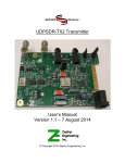
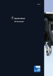
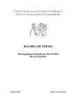
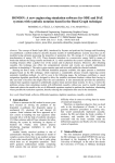
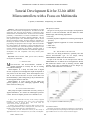
INTERNATIONAL JOURNAL OF CIRCUITS, SYSTEMS AND SIGNAL PROCESSING
Tutorial Development Kit for 32-bit ARM
Microcontrollers with a Focus on Multimedia
T. Sysala, P. Neumann, J. Pribyslavsky, M. Adamek
such processes control.
The goal of one our project was to design a development kit
based on a 32-bit microcontroller with the ARM core which
should comply with following requirements:
• Low costs,
• Extended peripheral equipment for interfacing technological
processes,
• Extended peripheral equipment for various communication
modes,
• Audio codec,
• Colour display.
Abstract— The article describes design and realization of a 32bit
ARM core microcontroller development kit. The ARM Cortex-M3
architecture with LPC1769 microcontroller is described in more
details aimed at the individual blocks. The LPC1769 microcontroller
potentiality is demonstrated on internal communication variants,
interrupt management and memory mapping philosophy. The real
time operation system is also mentioned together with its various
functions application benefits. The final solution is applicable in a
laboratory for students enrolled for Microcomputers subject where
programming and peripheral control is taught. That microcontroller
kit is also possible to be employed as a cheap controlling device in
various automation areas. As the development kit comprise even the
network connection possibility, color display, and audio output, it
can serve as a cost effective alternative for multimedia application
development tool well comparable with many mobile phone
applications.
III. THE ARCHITECTURE SELECTION
There were two fitting architectures, optionally also with
relevant microcontroller type, for our design, namely
ARM7TDMI and ARM Cortex-M3 architectures.
In spite of the fact that we can find processors with the
ARM7TDMI core in millions device throughout the World,
that architecture dated to 1994 is declining, and the ARM
company itself is not recommending it for new designs [3].
The Cortex-M3 architecture is its successor.
Keywords—Microcontroller, ARM, process control, education,
development kit, multimedia.
I. INTRODUCTION
M
ICROCOMPUTERS and microcontrollers constitute a
common ingredient in our daily life. We are meeting
them without noticing it.
Microcomputers as a cheap and small form of digital
devices (computers) lived through their rapid development in
early 80-ties of the last century. Those microcomputers were
first in 8-bit version and later in 16-bit version then. The
model Intel8080 [1] and/or Zilog Z80 [2] may be mentioned as
the most popular models at that time.
Microcomputers in 32-bit version with the ARM core
gained popularity in more challenging application during
90ties of the last century [16].
II. GOAL AND SPECIFICATIONS
Many subjects taught at Tomas Bata University, Faculty of
Applied Informatics, are oriented at technological processes
control. The microcomputer presents one of alternatives for
T. Sysala is with Tomas Bata University in Zlin, Faculty of Applied
Informatics, nam. T.G.Masaryka 5555, 760 01 Zlin, Czech Republic
(corresponding author to provide phone: +420 57 603 5260; fax:
+420 57 603 2716; e-mail: [email protected]).
P. Neumann and M. Adamek are with Tomas Bata University in Zlin,
Faculty of Applied Informatics, nam. T.G.Masaryka 5555, 760 01 Zlin, Czech
Republic (e-mail: [email protected], [email protected]).
J. Pribyslavsky was with Tomas Bata University in Zlin, Faculty of
Applied Informatics, nam. T.G.Masaryka 5555, 760 01 Zlin, Czech Republic.
Issue 2, Volume 7, 2013
Fig. 1 Comparison of ARM architectures [10]
ACKNOWLEDGMENT
The authors wish to thank to the Ministry of Education, Youth and Sports
of the Czech Republic (the European Regional Development Fund under the
project CEBIA-Tech No. CZ.1.05/2.1.00/03) for financial support.
126
INTERNATIONAL JOURNAL OF CIRCUITS, SYSTEMS AND SIGNAL PROCESSING
The most remarkable difference lies in the fact that
ARM7TDMI is based on the von Neumann architecture while
Cortex-M3 is based on the Harvard architecture. From the
practical point of view, the Cortex-M3 higher efficiency is
related to its 1.25 DMIPS/MHz unlike the ARM7TDMI which
offers only 0.95 DMIPS/MHz. The energy consumption
comparison also favours the Cortex-M3 with 0.19mW/MHz
unlike the ARM7TDMI with 0.28mW/MHz.
The Cortex-M3 architecture disposes of many remarkable
features. Among the others, we can mention the program
branching prediction, the interrupt faster response (12 clock
cycles vs. 24-42 clock cycles at ARM7TDMI), hardware
implemented advanced debugging interface, reduced energy
consumption modes, and a sophisticated memory lock system.
There is a more detailed description of both architectures
differences in the ARM company official report [4].
All above mentioned qualities have influenced the final
ARM Cortex-M3 architecture selection with LPC1769
microcontroller.
Fig. 2 - LPC1769 microcontroller block diagram [11]
Issue 2, Volume 7, 2013
127
INTERNATIONAL JOURNAL OF CIRCUITS, SYSTEMS AND SIGNAL PROCESSING
such buses and each of them is managing its own peripheral
group. That makes a higher communication speed achievement
possible. The AHB bus communication employs a special
interface (AHB-to-APB-bridge).
Multilayer AHB Matrix is a circuit which acts as interface
among core buses, AHB buses, and it facilitates the
communication with APB bus interface. Each high speed
peripheral is allocated its own communication channel thanks
to that circuit and its communication frequency range is not
charged with other peripherals.
DMA channel (Direct Memory Access) is a kind of
interface enabling the data transfer either between memories or
from a peripheral to memory (and vice versa) without charging
the processor during the whole transaction period. The
processor acts only as a mediator for transaction opening and
termination instead of performing instruction at every data
word transfer. LPC1769 microcontroller owns 8 DMA
channels for general purpose (GPDMA), but some high speed
peripherals have their own (dedicated) channel.
IV. LPC1769 MICROCONTROLLER POTENTIALITY
Whereas the ARM Cortex-M3 core and its associated
debugging interface are ARM Ltd. products, all other elements
incorporated in the microcontroller are specified by the
semiconductor manufacturer. The simplified LPC1769
microcontroller block diagram illustrates Fig. 2.
A. Internal communication
Fig. 2 shows that the microcontroller core is interconnected
with rest of circuitry via three buses: System bus, data bus (Dcode bus) and instruction feed bus (I-code bus).
We can find another two main buses in LPC1769 internal
circuitry:
• AHB bus (Advanced High-performance Bus) supports
direct high speed communication between the microcontroller
core and some selected peripherals. DMA controller, Ethernet
MAC and USB are included.
• APB bus (Advanced Peripheral Bus) interconnects the
other peripherals of LPC1769 microcontroller. There are two
Fig. 3 The CM3board block scheme
Issue 2, Volume 7, 2013
128
INTERNATIONAL JOURNAL OF CIRCUITS, SYSTEMS AND SIGNAL PROCESSING
uSD card slot. uSD card can serve for storing bitmap files and
animation sequences. Display module can communicate with
external devices via RX and TX TTL signals similarly like an
UART circuit. That communication variant is preferred in the
CM3board design, and MCU LPC1769 reserves the UART1
port for it.
This module can operate in two modes. In the first mode, it
acts as a serial slave, and it executes commands sent to it.
Those commands can comprise for instance, text or bitmap
displaying, screen delete, or vector graphics drawing. In the
second mode, it acts independently when its controller
executes a program written in 4DGL script language [6]. The
serial communication here is also possible.
The OLED display module has the resistive touch screen
including relevant module for reading and calibration. From a
designer point of view, it is possible to work with the touch
sensitive surface as with an input device offering two
coordinates position.
B. Memory mapping
LPC1769 microcontroller holds a Flash memory of 512 kB
for program storing and a SRAM memory of 64 kB for data
storing. The whole processor memory is unified and exploits
the common memory space. The addressable space is 4GB in
relation to the 32-bit bus (I-code bus and D-code bus). As
both buses operate in the same address space, the capacity is
not double like it can seem to be.
The individual memory parts have their addresses fixed in
the memory space, and it is not possible to change them. The
only exception is the interrupt vector table.
C. The interrupt control system
ARM Cortex-M3 core holds a special controller for
interrupt control and serving. That controller is indicated with
acronym NVIC (Nested Vectored Interrupt Controller).
In case of LPC1769 microcontroller, the NVIC offers
following functions:
• 35 peripheral maskable interrupts,
• 32 programmable priority levels,
• the vector table re-mapping possibility,
• non-maskable interrupts support,
• software interrupts support.
Vector table
It is a specific memory area where interrupt vectors are
stored. Each vector includes the serving function address for
the particular interrupt event. The LPC1769 microcontroller
original factory setting positions the table origin at the address
0x00000000 what is the very beginning of the address space.
Nevertheless, it is possible to remap that table to another
address, either in Flash memory or in SRAM memory. Such
remapping is used especially when the address space
beginning is occupied by the user boot-loader program. The
detailed information on interrupts, their vectors and on table
remapping procedures is described in the LPC17xx family user
manual [11].
Non-maskable interrupts
This sort of interrupt cannot be generated in a common way.
It is frequently generated in cases when the system gets in a
intangible state due to a serious error. Non-maskable interrupts
have their own servicing functions which can help a designer
in a more detailed system diagnostics in case of such error
occurrence. A special non-maskable interrupt variant is the
system reset.
B. The 24-bit stereo Audio CODEC
The 24-bit stereo Audio CODEC with I2S interface,
integrated driver for headphones and 8 to 96 kHz sampling
frequency support can exploit many audio functions. It
integrates individual components like A/D converter, D/A
converter, amplifiers and other supporting circuits. It creates
an interface between the digital and analogue device part with
bidirectional information flow.
There has been the Texas Instruments TLV320AIC23B
integrated circuit chosen for CM3board. That component is
marked as IC7 [7]. It is a mixed signal circuit with digital and
analogue ground potential separated. The supply voltage is
also separated in similar way.
That circuit integrates following functional blocks:
• Two channels sigma-delta D/A converter,
• Two channels sigma-delta A/D converter,
• Power amplifier for headphones direct connection,
• Input circuitry for electret microphone direct connection,
• Digital interface for sound transfer,
• Digital interface for circuit functions control,
• Clock generator and timing circuitry.
AD and DA converters
Those circuits are indispensable for audio interface
establishing. The IC7 circuit integrates 4 channels (2 for inputs
and 2 for outputs). All channels employ sigma-delta
modulation and they function up to sampling frequency of 96
kHz. All converters have resolution of 24 bits.
Headphone amplifier
The headphone amplifier can drive earphone with
impedance of either 16 Ohms or 32 Ohms. The headphone
amplifier is equipped with volume control, mute mode and it
can also suppress interfering audio effects like crackling noise
or knocking noise. The amplifier provides up to 40 milliwatt
power in each channel for 16 Ohms headphone impedance.
The total harmonic distortion (THD) is of 0,1% at 10 milliwat
power. [18]
The headphone amplifier output signal on the CM3board is
V. THE CM3 DEVELOPMENT BOARD
The further step was the interfaces and peripheries set for
the board. The CM3board block scheme is in Fig. XX.
A. Colour OLED display module
The colour OLED display module with resolution of
320x240, and with integrated intelligent controller, is the
product of Australian 4D systems company [5]. That module is
an encapsulated unit with entirely autonomous application
possibility. The unit consists of OLED panel, intelligent
controller, supporting circuits like supply voltage block and
Issue 2, Volume 7, 2013
129
INTERNATIONAL JOURNAL OF CIRCUITS, SYSTEMS AND SIGNAL PROCESSING
fed to the connector X1 via two separating capacitors C29 and
C30 which suppress the DC signal component.
Microphone input
As well as headphone amplifier, the microphone input has
the volume control and signal mute mode. The microphone
signal is amplified in two stages. The first stage represents an
operational amplifier in the MICIN input. That amplifier has
the gain adjustable with external resistance in series with this
input. The gain without the resistance is set to 5. The second
amplifying stage is digitally adjustable and provides the gain
either of 0 dB or 20 dB. More information about gain
adjustment can be found in the circuit datasheet [18].
The microphone input shares the same AD converter with
audio input channel so that it is not possible to use both
functions at the same time. However, it is possible to mix the
microphone signal with the DA converter signal together.
The microphone is connected to the JP8 connector on the
CM3board. The design is but represented with a multi way
strip where the biasing voltage for electrets microphone
(MICBIAS signal at IC7) and 3.3V supply voltage are lead out
besides the microphone input and ground for analogue signal.
The supply voltage of 3.3V is filtered with L1, C33 and C34.
Audio digital transmission
The IC7 circuit supports 4 audio digital transmission modes
in total. These are as follows:
• Right-justified – bits are aligned to the right within one data
word framework
• Left-justified - bits are aligned to the left within one data
word framework
• DSP – a special mode for communication with Texas
Instruments DSP circuits
• I2S – audio digital transmission bus developed by NXP
These modes are described in more details within the IC7
circuit datasheet [18]. The CM3board is preferably aimed at
audio transmission via I2S.
Circuit functions control
The IC7 circuit is controllable with writing in or reading
from relevant registers. The communication with those
registers can proceed, either via I2C or SPI bus. As both SPI
buses on the CM3 board are occupied with high speed
communication with SD cards, it was reasonable to use just the
I2C bus for the IC7 circuit control. That I2C bus is shared with
other circuits using the lower speed communication. Table 1
illustrates the IC7 register map.
Amplifier and acoustic transducers for loud audio replay
The load audio replay mode is supported with two audio
transducers and a stereo amplifier embedded in the CN3board.
That support is integrated in the IC8 circuit [19]. That circuit
has been designed for mobile applications so that the low
consumption and high efficiency is preferred. The circuit is
formed by two operational amplifiers and it can reach the
power of two times 105mW in 16 Ohms loudspeakers and at
5V supply voltage. As the CM3board is fed only with the 3.3V
power supply, the maximum loud audio power output is only
40mW for each channel. In spite of that, the power is adequate
Issue 2, Volume 7, 2013
for informative audio monitoring with SP1 and SP2
loudspeakers.
Table 1 - TLV320AIC23B register map [18]
The circuit power supply is separated with the LC filter
composed from L3, L4 and C46. The circuit has also an
independent analogue ground. Loudspeakers are connected to
the output via serial capacitors C48 a C49 which are
suppressing the DC signal component. Loudspeakers can be
disconnected with help of jumpers JP12 and JP13. The circuit
can be digitally controlled via three signals which are
recognised by MCU as GPIO pins. SPSHTDN signal enables
the amplifier switch off while SPCLK and SPUPDN signals
serve for a volume control. All these signals are controlled
with simple pulses without any special interface.
C. The Ethernet interface with integrated physical layer
controller
The LPC1769 does not implement the Ethernet physical
layer feature like the native USB. It is implemented with RMII
interface here [8]. That interface is a reduced version (using
lower count of signal lines) of the MII (Media Independent
Interface). That is a device designed exactly for MAC device
separation from physical layer (PHY circuit) what causes its
complete independency. So it is possible to connect a MCU
with a physical layer implemented with any media (metallic
cable, optical cable, wireless connection) without any
influence on the MCU.
The CM3board implements the Ethernet interface with a
standard metallic cable.
D. The RS422/485 communication channel
These interfaces are both implemented with the only
integrated IC17. Nevertheless, only one interface mode at time
can be operated. That IC17 is ordinarily designed for the
RS485 mode and the RS422 mode changes to the point-topoint topology
E. Sensors for non-electrical quantities
Our development kit also supports the non-electric
quantities measurement, like illumination intensity,
temperature and acceleration.
The temperature sensor represents the IC22 circuit. That
130
INTERNATIONAL JOURNAL OF CIRCUITS, SYSTEMS AND SIGNAL PROCESSING
circuit measures temperature in the range between -55°C and
+125°C. It can act not only as a continuously measurement
unit but also a thermostat. If temperature exceeds the set limit,
that circuit issues the interrupt signal on the TSINT line. That
signal appears at the MCU common input pin so that it cannot
cause a real interrupt response. Only in case of necessity, that
pin state is to be monitored by software. That signal can be
optionally disconnected.
CM3board holds the ambient light sensor IC20 for the
display brightness control, and for the push buttons backlight
control. Like the temperature sensor, it has an interrupt signal
output for a situation when the ambient light exceeds the set
limit. That circuit has an internal filter for flickering rejection
at frequencies of 50 Hz and 60 Hz what is a frequent problem
at artificial light sources. The ambient light is sensed with two
integral photodiodes. One of them is sensitive only for the
infrared spectrum the other one senses the infrared and visible
spectra together. That two-photodiodes combination optimizes
the sensor sensitivity close to the human eye characteristics.
Accelerometer detects vibrations, drops, tapping (for
example on the display), position change or mechanical shock.
The acceleration sensing unit is represented by IC21.
•
•
•
•
•
VI. REAL TIME OPERATION SYSTEM
The continuously growing nowadays microprocessors´
capacity is accompanied with growing requirements in
application areas. While the last century 70s and 80s
processors common programming language was assembler, the
nowadays processors are commonly using higher level
programming languages. The object programming concept and
software platform like .NET and Java represent no exception
at nowadays microprocessors.
Not only programming languages are determining the
development trends in this specialized area. The increasing
demand on real time applications has evoked the formation of
application specific operation systems. The RTOS systems
have occupied its firm position in the industrial praxis. Unlike
common personal computers operation systems, these systems
are very specific and their presence in the particular equipment
is not necessarily recognizable for the user. We can encounter
them almost everywhere from consumer electronics like toys,
white goods, PC accessories and network components to
industrial automation systems, automotive industry,
biomedical engineering or space research.
The current market offers a wide range of such systems
for commercial and non-commercial applications. These
systems are sometimes accessible without charge like opensource systems. One of them is the FreeRTOS system.
F. Data storing
CM3board contains the 8 kB external EEPROM memory
with I2C bus. That memory is represented by IC19 (36) circuit
and its address can be jumper adjusted. That memory can store
a small data amount like device user configuration, events log,
errors log, and/or peripheral device measurement data.
If we need to store larger amount of data, like audio files,
image files, long term recorded data, or MCU new firmware
files, CM3board offers two slots for either SD card or for X8
and X9 MMC card. These cards are mutually independent and
each card communicates via autonomous SPI bus with DMA
channel utilization possibility. The slot power supply is
separated with LC filters which are connected to MCU via
jumpers so that it is possible to disconnect them easily. For
case cards are inserted in slots during disconnection, their data
lines have pull-up resistors to ensure their logic levels to be
defined.
There is no card type support hardware-wise defined. As all
MMC, SD, SDHC, and new SDXC cards are hardwarecompatible, the particular card support is selectable with
software support. The theoretical SDXC memory capacity
limit is up to 2 TB.
A. Motivation for implementing RTOS
We can always ask the question whether to use RTOS or
not. Generally, smaller projects can be managed without it
while it can act as a very useful tool for the larger ones where
it can bring the higher level of organisation. The boundary
between a smaller and a larger project is always questionable
and that depends always on the particular situation evaluation
related to the architecture, real-time response requirements and
similar stumbling blocks.
A CM3board demonstration application is quite simple so
that it can do without RTOS. Nevertheless, the tutorial aspect
calls for RTOS implementing in the project.
It offers immediately a few advantages for the project:
• Timing abstraction – it is very likely the most useful benefit
in this demo application. The timing is not realized with
hardware timers or with delay loops, but the API RTOS is
used where we can pause some tasks for precisely set time
period and we can perform another activities in between.
• Increased modularity – tasks are mostly autonomous software
elements which can be treated separately. There are also
better possibilities for a team development in case of
rigorously defined autonomous task interfaces.
• Easier testing – the above stated implies that it is possible to
G. Further important kit components
The list of further important development kit components
follows:
• Native USB 2.0 interface with Device, Host, and OTG
support
• USB-UART converter with virtual serial port
• Integrated D-class amplifier, and two mini-loudspeakers
for loud listening incorporated in the board
• JTAG port for testing and application debugging
• CAN bus interface with two independent channels
Issue 2, Volume 7, 2013
Wireless XBEE module
Eight user push-buttons with programmable LED backlight
and innate I2C bus expander
Two rotary encoders
Serial 8 kB I2C EEPROM
Extension connector for external user hardware connection.
131
INTERNATIONAL JOURNAL OF CIRCUITS, SYSTEMS AND SIGNAL PROCESSING
task is the waiting task semaphore set (interrupt handler) for
the task with very high priority but blocked by waiting most of
time. Immediately when the semaphore is set, that task is
launched and exercises the interrupt relevant service [12].
test to a certain degree and debug the task in isolation from
environment.
• The processor idle time utilization – designer has a much
higher control over the processor time in case of multitask
system, and he can more precisely make use of it.
Processor usually performs activities only in case there are
any expected. It may not provide the full performance with
endless loops exercising during idle time, but it can switch
the whole circuitry in an energy saving mode, or it can
optionally perform some activities in the background.
F. Memory management
Working with FreeRTOS, it is possible to make use of
standard functions for the dynamic memory allocation, i.e.
malloc() and free(). These functions are not always suitable
because of relatively large implementation and with limited or
no accessibility for smaller systems. Another problem can be
related to the fact that these functions cause memory
fragmentation, and that they are not deterministic. The
multitask applications safe use is also not guaranteed.
FreeRTOS system implements three ways how to avoid those
problems. Each of those ways is implemented with separated
file.
B. FreeRTOS system potentiality
FreeRTOS system is almost exclusively written in C
language and its source code files can be smoothly embodied
in a C++ project. FreeRTOS is circulated under the GPL
licence and there is possible to use it free of charge including
its source codes. System is adopted on numerous architectures
which list you can find on the system official website [22].
G. Platform ARM Cortex-M3 specific functions
Majority of Cortex-M3 core microprocessors offer so
called MPU (Memory Protection Unit) what is a peripheral
facilitating the memory segmentation in autonomous regions
where each region is managed independently with its own
access rights. The LPC1769 microprocessor by NXP, for
instance, enables segmentation in 8 such regions [14].
FreeRTOS system owns functions for cooperation with
MPU on the Cortex-M3 platform. It is mainly the function
vTaskAllocateMPURegions() which enables to allocate the
autonomous region in the memory. With help of
vTaskCreateRestricted() function is formed a task then
exploiting that memory area. Many others such functions are
described in the on-line manual on FreeRTOS system website
[15].
C. Task management
FreeRTOS system offers a few API functions for task
management. They are its basic functions. It is possible to
create task with help of xTaskCreate() function and to cancel
it with help of xTaskDelete() function. Every task created has
to be implemented as an endless loop similarly like the main()
function. It is also possible to use task temporarily blocking
functions, for instance vTaskDelay(). FreeRTOS system
implements always at least one task, so called idle task which
has the lowest priority, and which runs always when no other
task is in the ready state. The first chapter of reference [12]
deals with task management or the information can be found in
the manual accessible on the FreeRTOS official website [13].
D. Queues and inter task communication
Queues are generally used for communication among
tasks. They are autonomous objects encapsulating FIFO sort of
buffer in them. As well as tasks, queues have their API which
enables queues creation, deleting and also data storing and
withdrawal. Queues hold finite number of fixed elements
which qualities are specified during the queue formation.
Tasks own functions that facilitate the waiting in a blocked
state until data comes in the queue, or until a queue free space
emptying enables the data [12].
VII. SOFTWARE
There is possible to utilize many development environments
for application software design. Each of them has its
advantages and disadvantages, like price, user-friendliness,
non-standard functions utilization etc.
Among most exploited development environments, we can
mention Eclipse with Cygwin GNU ARM Tool-chain [9] or
YAGARTO supplements, furthermore Keil, IAR, Red Suite.
That is the Red Suite light version named LPCXpresso
which has been used in our project. Although it supports only
C programming language, and the program size is limited to
128 kB, it represents a so called download limit what means
the program size to be written and developed with the help of
debugger. There is no limit for program compilation. This is a
free version and it represents an excellent combination with
identically named development tools by Embedded Artists
company.
The microcontroller operation control is exclusively
managed by the user.
There has been created a simple demonstration program for
CM3board. The demonstration of multimedia elements is preeminently accented in that program. The multimedia
E. Semaphores and interrupt management
Semaphores serve also for mutual task communication
preferably for their synchronization. We differentiate the
binary and counting semaphores. Semaphore can be
interpreted as a queue containing only one element in case of
binary semaphore, or optionally more elements in case of
counting semaphore. Unlike the standard queue, the element
content is not important only its presence or absence in the
“queue”, more accurately in the semaphore. As well as queues,
also semaphores are objects by themselves and FreeRTOS
owns API functions for their creation, deleting and controlling.
The task synchronization with an interrupt belongs among
semaphores frequent applications. The particular interrupt ISR
Issue 2, Volume 7, 2013
132
INTERNATIONAL JOURNAL OF CIRCUITS, SYSTEMS AND SIGNAL PROCESSING
demonstration is aimed at the static pictures stored in the
touch-sensitive OLED module SD card browsing.
We can summarize the individual steps of demo application
design in following items:
• OLED module application design aimed at the graphics
loading and displaying including the serial
communication with the CM3board.
• Controller design for the PCA9555 circuit embedded in
the CM3board.
• Creation of the push-buttons operation library for
PCA9555 disposal.
• A simple protocol design for communication between
OLED module and CM3board.
• Application layer creation with the help of FreeRTOS
system.
Except for the above mentioned items there were also other
software elements used for our application:
• FreeRTOS system libraries,
• CMSIS library,
• LPC1769 circuit peripheral controllers.
[6]
[7]
[8]
[9]
[10]
[11]
[12]
[13]
VIII. THE DEVELOPMENT KIT COMPONENTS
[14]
The development kit does not comprise only the main
board, but it includes many options for applications support as
well.
The support option set contains the following items:
• Switching power supply adaptor 9 Volt
• 3Mini USB cables
• User manual and
• CD ROM with development environment demo version
and with application examples
• Colour OLED module
• Transportable suit-case
[15]
[16]
[17]
[18]
IX. CONCLUSION
There has been a new 32-bit ARM core microcontroller
development kit designed in the frame of our project. A
prototype has been manufactured for all required functions
verification. The final device has a variety of applications
comprising both the student laboratory educational activities
and the cheaper control devices development for various
automation areas.
[19]
[20]
[21]
REFERENCES
[1]
[2]
[3]
[4]
[5]
Intel Museum: Journey Through Decades of Innovation, Intel
Corporation, [Online] 2012. Available: http://www.intel.com/content/
www/us/en/company-overview/intel-museum.html.
Zilog Embedded in Life, Zilog, Inc., in[Online] 2012. Available:
http://www.zilog.com/
ARM7 Processor Family - ARM. ARM - The Architecture For The
Digital World. [Online] 2012. Available: http://arm.com/products/
processors/classic/arm7/index.php.
“Sadasivan, Shyam. An introduction to the ARM Cortex-M3
Processor”. ARM – The Architecture For The Digital World. [Online]
2006. Available: http://www.arm.com/files/pdf/IntroToCortex-M3.pdf.
“4D Systems, Research and Development. 4D Systems, Research and
Development”, [Online] 4D Systems Pty Ltd, 2007. Available:
Issue 2, Volume 7, 2013
[22]
[23]
[24]
133
http://www.4dsystems.com.au/
“4DGL programmers reference manual. 4D Systems”, Research and
Development, [Online] 4D Systems Pty Ltd, 2010. Available:
http://www.4dsystems.com.au/downloads/4DGL-Docs/4DGLProgrammers-Reference-Manual-rev2.pdf.
Analog, Embedded Processing, Semiconductor Company, Texas
Instruments. Analog, Embedded Processing, Semiconductor Company,
Texas Instruments. [Online] Texas Instruments Incorporated, 19952012, Available: http://www.ti.com/lit/ds/symlink/tlv320aic23b.pdf.
RMII Specification. National Semiconductor| High-performance
Analog. [Online] 2012, Available: http://www.national.com/
assets/en/other/rmii_1_2.pdf.
C., Rick. “GNU ARM toolchain for CygWin, Linux and MacOS”. GNU
ARM toolchain for CygWin, Linux and MacOS. [Online] 2006.
Available: http://www.gnuarm.com/.
“ARM - The Architecture For The Digital World”. ARM - The
Architecture For The Digital World. [Online] ARM Ltd., Copyright
2012. Available: http://arm.com/.
NXP Semiconductors. LPC17xx User manual - Rev. 2. [Online] 19. 8
2010.
Available:
http://www.nxp.com/documents/user_manual/
UM10360.pdf.
Barry, Richard. Using the FreeRTOS Real Time Kernel - NXP LPC17xx
Edition. 2010. 978-1-4457-4664-7.
Tasks and Co-routines. FreeRTOS-A Free professional grade RTOS
supporting 31 architectures. [Online] 20. 3 2012.
Available:
http://www.freertos.org/taskandcr.html.
LPC17xx user manual. NXP Semiconductors. [Online] 19. 8 2010.
Available: http://www.nxp.com/documents/user_manual/UM10360.pdf.
FreeRTOS-MPU Specific Functions. FreeRTOS - A FREE Open Source
RTOS. [Online] 29. 4 2012. Available: http://www.freertos.org/
FreeRTOS-MPUspecific. html.
A. Qamar, J. Iqbal, I. Javed, Ishaque, H. Rehan, “Design and
manufacturing of a real time imitation based robotic arm using low cost
microcontroller”, Proceedings of the 6th WSEAS International
Conference on Applied Informatics and Communications, Elounda,
Greece, August 18-20, 2006 (pp363-368).
V. C. Petre, „Microcontroller based measurements : how to take out the
best we can of them”, Proc. of the 8th WSEAS Int. Conf. on
Mathematical Methods and Computational Techniques in Electrical
Engineering, Bucharest, October 16-17, 2006.
Analog, Embedded Processing, Semiconductor Company, Texas
Instruments. Analog, Embedded Processing, Semiconductor Company,
Texas Instruments. [Online] Texas Instruments Incorporated, ©
Copyright 1995- 2012. Available:
http://www.ti.com/lit/ds/
symlink/tlv320aic23b.pdf.
Analog, Embedded Processing, Semiconductor Company, Texas
Instruments. Analog, Embedded Processing, Semiconductor Company,
Texas Instruments. [Online] © Copyright 1995 - 2012. Available:
http://www.ti.com/lit/ds/symlink/lm4811.pdf.
S. Y. Cho, “A virtual development environment for smart card
applications”, Proceedings of the 12th WSEAS International
Conference on Automatic Control, Modelling & Simulation, Catania,
Sicily, Italy, May 29-31, 2010.
P. Navratil, L. Pekar, “Combined production of heat and electric energy
– linear mathematical model”, Proc. of the 16th WSEAS International
Conference on Circuits, Kos Island, Greece, July 14-17, 2012.
Microcontrollers and compiler tool chains supported by FreeRTOS.
FreeRTOS-A Free professional grade RTOS supporting 31
architectures. [Online] 2012. Available: http://www.freertos.org/
RTOS_ports.html.
J. Pribyslavsky, “Vyvojovy kit pro 32-bitové mikrokontrolery ARM se
zamerenim na multimediálni aplikace (in Czech) - Development kit for
32-bit ARM micro-controllers with a focus on multimedia
applications”, diploma thesis, Faculty of Applied Informatics, Tomas
Bata University in Zlin, Zlin, 2012.
Mahmut Meral, M. Gokmen, “Isolated word recognition on an
embedded system”, Proceedings of the 6th WSEAS International
Conference on Multimedia Systems & Signal Processing, Hangzhou,
China, April 16-18, 2006 (pp204-207).