1
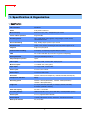
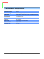
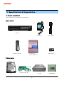
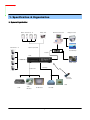
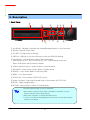
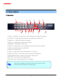
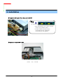
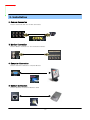
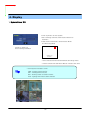
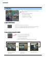
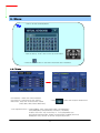
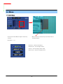
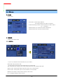
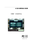
Stand Alone Type
DVR
SYSTEM
Embedded DVR
USER’S MANUAL
Thank You
Thank you for purchasing our Digital Video Recorder.
Before operating the system, please read this User’s Manual thoroughly and
retain it for future reference.
Revision Date : 2006. 10. 01
Firmware Version :
Ex-Factory Date :
※ Picture might differ according to the specifications
050905
060829
061001
• INDEX
• CHAPTER 1. Specification & System organization
1. Specification -------------------------------------------------------------- 4
2. Product Contents List -------------------------------------------------------- 6
3. System Organization --------------------------------------------------------- 7
• CHAPTER 2. Description
1. Front Panel --------------------------------------------------------------- 8
2. Rear Panel --------------------------------------------------------------- 9
3. Remote Controller ---------------------------------------------------------- 10
• CHAPTER 3. Installation
1. Hard Disk Installation ------------------------------------------------------- 11
2. CD-RW & Hard Disk Installation ----------------------------------------------- 13
3. Camera Connection -------------------------------------------------------- 15
4. Monitor Connection -------------------------------------------------------- 15
5. Computer Connection ------------------------------------------------------- 15
6. Network Connection -------------------------------------------------------- 15
7. Alarm/Relay/PTZ Connection ------------------------------------------------- 16
8. Power Connection --------------------------------------------------------- 16
9. Finishing Installation -------------------------------------------------------- 17
※ Hard Disk Format ---------------------------------------------------------- 17
• CHAPTER 4. Display
1. System Power ON ---------------------------------------------------------- 18
2. Screen View Selection ------------------------------------------------------ 19
3. Screen Rotation Mode (SCR MODE) -------------------------------------------- 19
4. PTZ/FOCUS Control -------------------------------------------------------- 20
5. System Power OFF --------------------------------------------------------- 20
• CHAPTER 5. Search
⊙ Go to Search Mode --------------------------------------------------------- 21
1. Search by Date/Time ------------------------------------------------------- 21
2. Search by Event ----------------------------------------------------------- 22
• INDEX
• CHAPTER 6. MENU
⊙ Go to Menu -------------------------------------------------------------- 24
⊙ Go to System Setup -------------------------------------------------------- 24
1. Display ------------------------------------------------------------------ 25
2. Camera ----------------------------------------------------------------- 26
3. Audio ------------------------------------------------------------------- 29
4. System ------------------------------------------------------------------ 29
5. Event/Sensor ------------------------------------------------------------- 35
6. Disk Management ---------------------------------------------------------- 38
⊙ Go to Record Menu -------------------------------------------------------- 39
1. Recording Operation -------------------------------------------------------- 39
2. Continuous/Motion Record Schedule -------------------------------------------- 40
3. Alarm Record Schedule ----------------------------------------------------- 41
⊙ Go to Archiving ----------------------------------------------------------- 42
1. CD-RW and USB Back up --------------------------------------------------- 42
1. Specification & Organization
1. Specification
Video standard
PAL/NTSC
Audio
2-way Audio conference
Monitor display
Real time:25 Fps (PAL), 30Fps(NTSC) per camera
Covert camera operation
Programmable
Event/Log search
Up to 1,000,000 for user login/out, config changes, remote access,
connects/disconnects
Record Scheduling
Daily, Weekly adjust specific Hr per channel
Remote Access
TCP/IP, View, Search, Recording & Control by Client Program or I.E.
Playback
Single and quad picture
Pre/Post alarm recording
5 secs(Pre), 3 mins(Post), programmable per camera
VGA
For monitors with Multi Sync Function only(1024 X 768(60Hz))
Activity detection
12x12 grid, Sensitivity levels: 10
Simplex/Duplex operation
Triplex
Video inputs
4 x 1Vp-p, CVBS, 75ohms, BNC, looping inputs
Monitor outputs
1 x CVBS/S-VHS, VGA (option)
Spot output
1 x 1Vp-p, CVBS, 75ohms, BNC
Audio inputs
4 x line-in, RCA sockets
Audio output
1 x line-out, RCA socket
Resolution
352x240,704x240,704x480(NTSC), 352x288,704x288,704x576(PAL)
Compression standard
Mpeg4
Recording speed
352x240 : 120/100 (NTSC/PAL) , 704x240 : 60/50 (NTSC/PAL)
704x480 : 30/25 (NTSC/PAL)
Image size
3-5 Kbyte (352x240, 352x288), 5-10 Kbyte (704x240, 704x288)
6-16 Kbyte (704x480, 704x576)
Hard disk capacity
2 X HDD + 1 X CD-RW
Secondary Storage
USB default(USB memory stick, USB HDD), CD-RW(400SNX: option)
Alarm inputs
4 x TTL, programmable as NC/NO
Alarm outputs
1 x Relay with NO/NC contact; 30VDC/1A, 125VAC/0.5A resistive
Back-up file formats
AVI, JPG, BMP
4
1. Specification & Organization
Network Speed Control
8 levels
Pre-alarm recording
Up to 5 sec., programmable per camera
OSD languages
English, Spanish, Chinese, Dutch, Portuguese, French, Russian, Japanese,
Polish, Romanian, German
Ethernet interface
10/100-Base-TX, RJ-45
Remote Function
Live View, Live Recording, Search, Set-up, Back-up
PTZ Control
RS-485 interface
Supply voltage
100VAC-240VAC, 12V 5A DC, 60/50Hz
Power consumption
Approx. 60watts
Temperature range
5℃ to 50℃
5
1. Specification & Organization
2. Product contents List
Please Confirm the Contents When open Package.
① Basic Contents
DVR Unit
12V Adaptor
Remote Controller
User Manual &
Remote Software CD
Power Cable
AAA Battery X 2
② Option Contents
HDD
VGA OUT Install Kit
CD-RW
6
USB MOMORY
1. Specification & Organization
3. System Organization
Alarm Sensor #1-4
Camera #1-4
Remote Client PC
Relay Out
Image Printer
Alarm Input/Out
NETWORK
AVI Backup
TCP/IP
DVR
Video In
WEB Client
Video Out
Backup
Remote
Controller
USB
VCR
VGA
Monitor
CD-RW
AV Monitor
7
2. Description
1. Front Panel
①
③
②
④
⑥
⑦
⑨ ⑪ ⑩
⑧
⑤
⑬
⑫
① Jog Shuttle : Playback in different fast forward/backward speed, or frame by frame
② Remote Controller Sensor Input.
③ CD-RW : CD-RW Device for Backup.
④ USB Port: USB port for use the USB memory stick and USB HDD Backup
⑤ Led Indicator : Indicate Present System Status Information.
( PWR: System On/Off , REC: Record On/Off , NET: Client Network Connection
Status, ALM: Alarm Sensor Detection Status )
⑥ Channel Selection Button : Select Channel or Input Password.
⑦ SCR MODE : Select Screen Division Mode or Rotation Mode.
⑧ SEARCH : Go to Search Mode for Searching Data.
⑨ MENU : Go to System Menu.
⑩ PTZ/FOCUS : Go to Camera PTZ/FOCUS Control.
⑪ Search Controller : Searching Recorded Data or Control Menu & PTZ/FOCUS.
⑫ ENTER : Apply Changing Setup.
⑬ RETURN : Cancel Setup or Return to Previous Mode.
Tip
• Channel Selection Button is Prior to SCR Mode.
• When Remote Controller Sensor Input is Blocked by Something, it Cause
1 Remote Controller do NOT Work Properly.
• When Press any Button, it Operate with Beep Sound.
• In Case of CD-RW, the Real Appearance will be Differ from the above Picture
1 Depends on its Model.
8
2. Description
2. Rear Panel
①
③
②
④
⑥
⑨
⑤ ⑦ ⑧
⑪
⑫
⑩
⑬
① Video In : BNC Port for Connection of DVR & Camera. (4 Camera Connectable)
② Loop Back : Output DVR Camera Video to Loop Back Port. (4 BNC Port)
③ Monitor Out : Output DVR Video to AV Monitor.
④ Spot Out : Output Spot-out Video to AV Monitor.
⑤ NTSC/PAL : Select NTSC or PAL Type.
⑥ VGA OUT : Output Video to a Computer Monitor by Connected VGA (Option)
⑦ SVHS : Output Video by Connected SVHS.
⑧ Audio Out : Output Audio.
⑨ Audio In : Audio Input Terminal Related with #1~4 Camera.
⑩ Ethernet (TCP/IP) : Port for LAN / Internet (for Remote Surveillance)
⑪ Alarm/Relay/RS-485 : Connect Port for Sensor, Relay, & PTZ.
⑫ RS-232C : Connect Port for Program Debug.
⑬ DC Power Input : Power Supply by DC 12V Adaptor.
Tip
• When System Installation, Please Install under System Power Off Status.
• Please Use Specific Adaptor when Power Supply.
9
2. Description
3. Remote Controller
POWER
System
ON/OFF
MENU: Open Menu
Channel Selection Button
(4ch Available, #1~4 Button)
RETURN
ENTER: Apply Setup Change
Cancel Setup
or Return to
Previous
Search Controller : Control Playback Option,
Menu Movement, PTZ/Focus Control
Change
Screen Mode
Open
Search Mode
PTZ/IRIS Mode
• Unused Button’s Description is Omitted.
• Every Button is Operated Same as Front Panel Button.
• Remote Controller can Operate when Remote Controller Sensor Input Part Reacted Each Other.
※ If there are many DVR at the same place, they are reacted together when press remote controller.
10
3. Installation
1. Hard Disk Installation
① Jumper Setup as Master or Slave
• Jumper Setup as master or Slave, Following the
` Direction of Surface of Hard Disk.
• Jumper Located at Hard Disk Data Cable or
1 Rear Side of Hard Disk.
• If One Hard Disk Installation, Setup as Master
If Two Hard Disk Installation, Second One Setup as Slave.
‼ When Hard Disk Add or Exchange, Must System Off
Properly. If not, it’s a Cause of Fatal Hard Disk Error.‼
※ Example of Samsung HDD Jumper Setup
• Refer to General Pin Setting in Jumper Pin Setting on HDD Surface.
• When One HDD Install, Setup Pin as Master and Connect Pin
1 at the Left End of Jumper.
• When Two HDD Install or Additional Install, First One Setup as
1 Master and the Other is for Slave. Slave Setup has No Pin.
• When More than Two HDD install, Setup as Master or Slave
1 to Connect One IDE Cable at the Same Method of Above.
!!Please Use Hard Disk which Possible to Supply Higher than
UDMA66.!!
② IDE Cable Connection to Main Board
• Confirm the IDE Cable Inside of Product
• Among the Three Connector, Indicated Blue Color
1 Connector Must be Connected with Main Board. Other
1 Connectors Connected with HDD
11
3. Installation
② After set jumper, attach Hard Disk with Screw & Bracket
HDD Bracket (Max. for 2 HDD)
③ Connect IDE Cable to Hard Disk
• Insert Disk, Red Cable Head to Power Cable Plug
• Connect Power Cable to Hard Disk in the Same Way
※ If One HDD Install, Connect with End of Connector (Black)
Recommended.
If Add HDD, Connect with Middle Connector (Gray)
Recommended.
Tip
For Rear Panel
IDE2
IDE1
• When Install Master HDD, Please Connect
1 at IDE1 Port by Master Cable.
• It means, Master Connector which
1 Connected with IDE1 Cable Must
1 Connected with HDD (Master).
ㅡMaster, Slave?
• IDE Hard Disk can connect two equipment at one
cable (port). For the purpose of prevent
confusing, two equipment named ‘Master’ &
‘Slave’. ’Master’ is one hard disk or first hard
disk and ‘Slave’ is below second hard disk.
12
3. Installation
1. CD-RW & Hard Disk Installation
① Jumper Setup as Master or Slave
• Jumper Setup as Master or Slave (Refer to CD-RW
1 Direction at the Surface).
• If Install One CD-RW at One IDE Cable, Setup as Master
If Install One CD-RW & HDD at One IDE Cable,
1CD-RW Setup as Slave.
‼ When CD-RW Install, Exchange, or Remove, Please
System Off Properly and Disconnect DVR Power.‼
Incase of LG-8526B, MASTER
② Install CD-RW at the bracket
③ After Assemble with Bracket, Attach to the Case
13
3. Installation
④ Connect by IDE Cable & Power Cable at the CD-RW
Tip
For Rear Panel
IDE2
IDE1
• When Install Master HDD, Please Connect
1 at IDE1 Port by Master Cable.
• It means, Master Connector which
1 Connected with IDE1 Cable Must
1 Connected with HDD (Master).
⑥ Example of Install CD RW & HDD
HDDx1
and
14
CD-RW
3. Installation
2. Camera Connection
Connect Camera at BNC Port in Back Side Panel.
3. Monitor Connection
Connect Monitor Terminal or S-VHS Terminal to Monitor
4. Computer Connection
Connect VGA OUT Terminal to Computer Monitor
5. Network Connection
Connect Ethernet Terminal and Network Cable
15
3. Installation
6. Alarm/Relay/PTZ Connection
①
②
③
① ALARM
Alarm Input - ‘IN1, IN2, IN3, IN4’ : Connect Sensor Input by Channel
‘GND’ : Connect Ground System
② RELAY
Alarm Output – ‘NO, NC’ : After Checking Alarm Output Type (Normal Open or Normal Close)
and Connect to ‘NO, NC’
‘COM’ : Connect Remain Grounding Conductor
③ RS-485
Connect PTZ Camera – ‘D+, D-’ : Connect PTZ Camera Control Line (+ , – Terminal)
RS485
PTZ 14 Pin Cable
D+
D-
⑨ R+
⑩ R⑪ T+
⑫ T-
Example of Connection PTZ Camera No. 14 Pin Connector
7. Power Connection
Connect DC Power Input Terminal and Specific Adaptor
16
3. Installation
8. Finishing Installation
System Start by Power Button after Finishing Installation
※ Hard Disk Format
- If Do Not New Hard Disk Format, System Can’t Recognize the HDD.
So it’s Same Situation of No HDD. Please Format HDD when Insert New HDD.
(Only Display Possible, Not Work Menu & Search)
Press any Button to
Power On
1. Power On
2. New HDD Format
(Select By Play , Backward Play Key)
When new discovery HDDs are two, It ask about each
format. Then choose the Yes about all HDDs. If you
Format the first HDD only, maybe second HDD don’t
Format.
※ When you are doing to format, Never turn off.
If turn off, HDD is able to occur fatal error.
3. System Start (Initial Mode)
17
4. Display
1. System Power ON
• Press any Button to Start System
• After Checking Hard Disk, Need input Password to
1 Operation
• Initial Screen View Mode is Quad Division Mode
1 and Recording Mode
Picture for Power On
after Finishing Installation
CAMERA
2005/01/01
00:00:00
• Each Channel Indicate Camera Name & Recording Status
• Present Time & Date Indicate at Monitor Central Lower Side
Tip
• Check System Condition at LED
PWR : Showing System On/Off
REC : Showing Record On/Off
NET : Showing Client Connection Status
ALM : Lighting when Sensor Alarm Activate
18
4. Display
When connect by the RemoteManager or Web Client ,
Indicator appear.
• Indicate the network condition.
Green: Network is stable.
Blue: Network is unstable.
Red: Network is very unstable.
2. Screen View Selection
• Select One Channel among 4 Channels
• Move to One Enlargement Watch Mode when Quad Screen Division Mode
CHANNEL
• Move to One Enlargement Watch Mode when Rotation Mode
3. Screen Rotation Mode (SCR MODE)
• User can Select 3 Kinds Watch Mode
① Quad (4CH) Division Watch Mode
② Selected 1CH Watch Mode
③ 4CH Rotation Watch Mode
• Quad (4CH) Watch Mode is Initial Mode when System Start
Quad (4CH) Division
Watch Mode
Selected 1CH
Watch Mode
19
4CH Rotation Mode
4. Display
4. PTZ/FOCUS Control
• Control Camera PTZ (Pan/Tilt/Zoom) & Focus (Only Useable for Proper Camera)
• Press PTZ/FOCUS Button to Open PTZ Menu at Right-Under Side and Control by
1 Search Controller
• Press PTZ/FOCUS Button Second Time to Open PRESET, SWING .FOCUS, IRIS
Menu and Control by Search Controller
• Each icon mean the button of front keyboard.
• F: Focus
I: IRIS
• Control each function by front keyboard.
5. System Power Off
• Select Shut Down to System Off
• Input Password and Press Enter to Shutdown System
Tip
• System Log-On Possible ID : ‘Administrator’, ‘Manager’, ‘User’
Administrator: All Function Access (System On, Shutdown, Setup, Search)
Manager: System On and Search
User: System On
20
5. Search
⊙ Go to Search Mode
• Press Search Button and Log-In
Administrator or Manager
• Use Direction Key to Move Menu
• To Open Each Menu Press Enter
1 or Press Play Button
• Return to Previous.
(Move to Previous Menu or Exit Search
1 Mode and Return to Watch Mode)
1. Search by Date/Time
- Possible to Search Recorded Date & Time
① Move Cursor to Selected Date in Calendar
(Recorded Date & Time Indicated by Gray Color)
② Press Enter to Open Selected Date
③ Recorded Time Appear to Under Side
④ Press Enter at Selected Time
(One Scale is 15 Minutes)
⑤ Menu Disappear and Output Recorded Video
• Showing Recorded Date & Time at Left-Upper Side
1 as Watch Mode.
1 Showing Playing Condition at Right-Under Side.
• Channel Selection Button in Watch Mode & SCR Mode
1 Button are Apply the Same as Search Mode.
(But Menu, Search, and PTZ/Focus Buttons are Exception)
21
2004/01/01
00:00:00
>
5. Search
• Control Playing Video
①
Basic Playing Mode (Normal Speed (1X) Forward Playing)
②
Normal Speed Backward Playing
③
Pause Video
④
Fast Forward (2 ~ 64 Speed)
⑤
Fast Backward (2 ~ 64 Speed)
⑥
②
⑤
④
③
①
⑥
⑥
Same Function as # ④,⑤
※ Press Normal Forward/Backward Button in Pause, Move to Next/Previous Frame.
2. Search by Event
- Searching Video with Event Occurrence to Set up Period
Set up Period to Select Start Date & Finish Date
for Searching Event
②
③
Alarm : Searching Alarm Event during the Selected
1
Period
Motion : Searching Motion Detected Event during
1
the Selected period .
①
Timer : Searching Schedule Change or Recording
1
Setup Change Event
④
System : Searching Power On/Off Event (etc.)
1
Concerned System Event
Channel: Choose the channel for searching.
Start: Start to search
Tip
• Alarm, Motion, System can be Select plural
• To Change Setup, Press Enter and Press Direction Key
After Changing Setup, Press Enter to Exit.
22
5. Search
• Date : Indicate Event Occurrence Order & Date
Time : Indicate Event Occurrence Time
Event : Indicate Event Contents & Camera No.
• Event Searching Method
① User can Search Event Using by Direction key
② Search Event to Press Enter at Selected Event
from Event Occurrence Time
③ Control Video is the same way as Time Mode Control
Tip
• The Search by Event is not Base on Video, but Event Occurrence Time.
23
6. Menu
⊙ Go to Menu
① Press Menu Button on Front Panel in Watch Mode
② Ask Password
③ Input Password Using by Channel Select Button
1 [1][2][3][4])
④ After Input Password Press Enter to See Menu
Tip
• Initial Administrator, Manager, User Password is 1234.
• Showing Password as *
• Changing Password (System setup->System -> User management )
• Only Watch Mode can go to Entering setup.
(Search & PTZ/Focus Mode can’t move to Menu)
⊙ Go to General setup
• Choose the “General setup”
24
6. Menu
1.Display
- Video Setup for Watch Mode
• Every System Setup can Change or Maintain
1 at Menu (6 Setup)
• Move to Menu Using by Up, Down,
Left & Right Button
• To Open Detail Menu, press “the Enter”
• Return to Previous Menu or Return to Watch Mode
1-1. OSD
• Status Bar : Record Condition Mark On/Off
(Recording: Red, Pre-recording : Green)
• Camera Title: Setup Camera Name to Show Left-Upper Side
• Event Icon: Indicate the menu location by icon
• Border : Border Mark On/Off when 4CH Division Watch Mode
• Border Color : Select Border Color
(White, Blue, Red, Yellow, Green, Gray)
• Alpha Blending: Choose the transparency(1~100)
1-2. MONITOR
• Sequence Dwell : Setup Rotation Cycle Time
(1~60 Sec.) when 4CH Rotation Mode at Watch Mode
• Spot-Out Dwell : Setup Spot-Out Time Cycle
(1~60 Sec.) to Transmit Video
• De-interlace Mode : Remove Screen Spread on High
Resolution , Low Frame ※Only Applying When D1(704X480)
• Alarm Pop-Up Mode: When alarm happen, Alarm happened
channel Pop-up
• Alarm Pop-Up Dwell: Alarm Pop-up Time(1~60Sec.)
Tip
• When finishing that change the setup data,
25
Press the
certainly.
6. Menu
2.Camera
- Setup Camera
2-1. Camera Title
• Covert : Setup Covert On/Off
*What’s Covert?
When Covert On Watch Mode, Display Video is Hidden, but Recording is On.
• Title : Setup Camera Name by Virtual keyboard
• Input the title by “Enter” after choose by arrow
button.
2-2. Color Setup
• Control the Monitor Bright, Contrast, Color, Tint
• All Setup Possible to Control 0~100
• Setup Channel by Channel
26
6. Menu
Tip
※ How to use the Virtual Keyboard
• Input the title by “Enter” after choose by arrow button
• Press the
button for shift then choose the other characters.
2-3. PTZ Setup
• PTZ Address : Select PTZ Camera Address
• PTZ Protocol : Select Kind of PTZ Camera
• Baud Rate : Setup PTZ Communication Speed
(2400, 4800, 9600,19200, 38400 BPS)
• Enter
button and setup the detailed PTZ
※PTZ Supplied Protocol : Samsung(MRX-1000), Samsung(SCC641),Honeywell(SD1)
Honeywell((GMC),Lilin(Fastdome), Fastrax(Ⅱ), GC(655N),
D-MAX, Sunin DSC-230, Scan Dome-Ⅱ, Vicon,Philips8560-700
Sensormatic,Panasonic(WV-CS850), Panasonic(WV-CSR604),VRX-2101
Kalatel(KTD-312), PELCO-D, PELCO-P,Dynacolor(D7722)
27
6. Menu
2-4. Motion Sersor
• Choose the Partial Motion Region channel by
channel
• Move Cursor by Direction Key and Press Enter at
Selected Region
• Sensitivity: 1~10
• Select All : Select Entire Region
• Deselect All : Cancel Region Setup
• Cancel : Cancel Change Setup & Exit
• Save & Exit : Save the Changes & Exit
28
6. Menu
3. Audio
- Audio Setup
• Live Audio : Audio Output ON/OFF
Live Audio Output from Audio In Terminal
• Audio Monitoring Channel: Select Channel for Audio Output
1
Nr. 1~4 Audio In
• Network Audio TX: Choose the Audio transmission
• Network Audio RX: Choose the Audio receive
4. System
- Basic Environment Setup
4-1. date/time
※ First of all, Timezone should be setup as your location.
• Date TIME: Setup Present Date
(If Time Setup to Past Date, Ask Delete Data for the Past Date.
NO->Date/Time No Change, YES->After Delete Past Data and Change Date/Time )
• Date Format : Select Date Output Type (Ex: 2005-00-00, 2005/00/00)
• Time Format : Setup Time Type as 12 Hour Base or 24 Hour Base
• Network Time Server: Setup Present Time by Time Server.
• D.S.T: Daylight Saving Function On/Off
29
6. Menu
• Time Zone: Choose the time by GMT standard.
Tip
※ How to Time setup
1.
2.
3.
4.
Setup Timezone as your location.
Setup the Network Time server and press the “Sync” button.
If correct time is not getted automatically, setup the date/time manually.
If don’t follow as upper, you may have the time error and the recording data search error.
30
6. Menu
4-2. Network
• IP Address : Input IP Address
• Gateway : Input Gateway IP for Internet Server
• Subnet Mask : Input Subnet Mask IP
• DNS Server: Input DNS Server IP
• Network Speed : Setup Network Speed
(Network Speed from System, Depend on Network Status)
※ If Change Network Setup, New Change Apply
when after Rebooting.
• DHCP (Dynamic Host Configuration Protocol) : Indicate IP Address for the DVR Automatically.
1.
2.
3.
4.
5.
Enter to ‘System -> Network’ on the Menu.
Setup DHCP On/Off.
DHCP Off : User Input IP Address by Himself.
DHCP On : After DHCP On, Reboot the System.
Can see the setup IP automatically at the system information.
• DDNS (Dynamic DNS): You can connect the DVR by the fixed domain name(ex.00115f000001.dvrlink.net) at
client or Web without entering the IP address.
※ If you use the DDNS, there is no necessity to enter again the IP Address every connection.
1.
2.
3.
4.
5.
6.
Enter to ‘System -> Network' on the menu.
Setup DHCP On or Enter the IP address.
Setup DDNS ON and reboot.
Enter to ‘System -> System information’ on the menu.
Confirm the MAC address.
The domain name is "MAC address.dvrlink.net".
EX) If Mac Address is 00-11-5f-00-b5-a7, the domain name is "00115f00b5a7.dvrlink.net"
7. If you connect by "00115f00b5a7.dvrlink.net" at client program or Web, you can connect the DVR.
Tip
※ 1. If your network connect at the router, please must port forwarding.
2. Please must enter the exact IP address, DNS Server, Gateway, Subnet Mask.
3. Please must connect the DVR at External Network.
If you don't follow 1,2,3 , you can't receive the DDNS service.
31
6. Menu
4-3. Mail
• Server: Setup the mail server
• Setup by Virtual Keyboard after press the “ENTER”
• Port: mail server port
• Security: On/Off
• User & Password: input the DVR login user ID and Password.
32
6. Menu
4-4. User Management
User setup
• It is consisted 3 User Group as Administrator,
Manager, User.
• Total 7 user belong to 3 User Group can be made.
• Input User ID, Password.
• Choose the Group.
• Input the E-mail Address.
• It can edit User ID information.
• E-mail notification On/Off
• Input the E-mail by Virtual Keyboard.
33
6. Menu
4-5. System Information
• S/W Version: Server Firmware Version
• Video Signal Type: NTSC or PAL
• Disk Capacity: used HDD capacity of the total HDD capacity
• IP Address: DVR’s IP Address
• MAC Address: Fixed MAC address of the DVR
34
6. Menu
4-6. Factory Default
• Press “Press” to Start Initialize.
• Showing Warning Message and Press OK to Run Initialize.
• If do Factory Default, Every Setup is Initialized, but Saving Image is Not Erase.
5. Event/Sensor
5-1. HDD Event
• Drive: HDD connected location
• Smart Alarm: On/Off
• Check interval: HDD checking Time
35
6. Menu
5-2. Alarm Input
• Operation: Setup Alarm Sensor Connection Status
(enable/disable)
• Type : Setup Alarm Sensor N/Open, N/Close Type
5-3. Alarm Output
※ Setup each channel when alarm, videoloss, motion are
happened.
• HDD Event: Alarm On/Off when HDD has the problem.
• Operation: Setup Relay Connect with Alarm Sensor.
• Mode: Setup Reacted Relay as Latched/Transparent Mode.
• Type: Setup Relay Type N/Open or N/Close.
• Duration: Setup Reacted Relay Time.
(5sec~5min or Until key-in)
Tip
• Latched/Transparent
Latched – When Sensor Alarm Activated, Relay Reacted in Setup Duration
Transparent – Relay Reacted Temporary During Sensor Alarm Activate
36
6. Menu
5-4. Buzzer out
• Buzzer: On/Off
• Duration: Buzzer time(5sec~5min or Until key-in)
• setup each channel when alarm, videoloss, motion are happened.
• HDD Event: Buzzer On/Off when HDD event is happened.
• Keypad : Setup Key Input Sound.
• Remocon: Setup remocon Input Sound.
37
6. Menu
5-5. E-mail Notification
• If the alarm, videoloss, motion and HDD event are happened,
send the notification at the E-mail.
• Choose the function by arrow button.
6. Disk Management
• Disk Overwrite : Select Overwrite Permission when Hard Disk Full
O N: Overwrite Hard Disk from Oldest Data
OFF: When Hard Disk Full, Stop Recording and Buzzer Activate
• Format : Refreshment Hard Disk. All Recorded Data Deleted
38
6. Menu
⊙ Go to Record Menu
1. Recording Operations
• Schedule Mode: Choose the DAILY or WEEKLY.
• Pre-Event Recording Time : Setup Pre-Event recording Time.
(1~5 sec)
• Post-Event Recording Time: Setup Post-Event recording Time.
(1~5 sec)
39
1
1
• Menu
2. Continuous/Motion Record Schedule
2-1. DAILY
• Continuous record setup
• Setup each channel
• Put the choose area at here and press “Enter” button.
• Motion record setup
2-2. WEEKLY
• Continuous record setup
• Setup each channel
• Motion record setup
• Setup each day
40
6. Menu
3. Alarm Record Schedule
3-1. DAILY
• Alarm record setup
• Setup each channel
• Put the choose area at here and press “Enter” button.
3-2. WEEKLY
• Alarm record setup
• Setup each channel
• Setup each day
41
6. Menu
⊙ Go to Archiving
①
②
③
⑦
④
⑥
⑤
① Device : Indicate CD-RW Model and USB MEMORY Model Automatically.
If you use the CD-RW and USB memory (or USB HDD) together,
it can choose the CD-RW and USB by Up & Down Button.
② Start Time : Select Start Backup Time.
③ End Time : Select End Backup Time.
④ Channel & Video/Audio Selection : Select Channel, Video, & Audio for Backup.
⑤ Title : Change the Title of Backup by virtual keyboard.
⑥ Event : Select Attach Event Text File in Backup.
⑦ Start : Start Backup.
Tip
• Compatible CD Writer Models are LG(GCE-8526B,GCE-8527B),
SAMSUNG(SW-252F, TS-H292A, SH-522C),ASUS(CRW-5232AS),GIGABYTE(GO-R5232B)
• Compatible USB memory stick Models are LG(Royal,mobile,mirror), IMATION(iflash),Memorive PRO+
and Compatible USB HDD is CUTIE(FHD-254).
• Inside of Backup CD,USB Including Necessary Codec for Playback (IMM4 Install File).
• In case of RW Possible CD, Please Delete Previous Data on PC for Recording Again.
42