1
OMRON
Getting Started with CX-Server OPC
CX-Server OPC
User Manual
Getting Started
Version 2.0
Page 1
OMRON
Getting Started with CX-Server OPC
Notice
OMRON products are manufactured for use according to proper procedures by a qualified
operator and only for the purposes described in this manual.
The following conventions are used to indicate and classify precautions in this manual. Always
heed the information provided in them. Failure to heed precautions can result in injury to
people or damage to the product.
DANGER!
Indicates information that, if not heeded, is likely to result in loss of life
or serious injury.
WARNING
Indicates information that, if not heeded, could possibly result in loss of
life or serious injury.
Caution
Indicates information that, if not heeded, could result in relatively
serious or minor injury, damage to the product, or faulty operation.
OMRON Product References
All OMRON products are capitalised in this manual. The word “Unit” is also capitalised when it
refers to an OMRON product, regardless of whether or not it appears in the proper name of the
product.
The abbreviation “PLC” means Programmable Logic Controller and is not used as an
abbreviation for anything else.
Page 2
OMRON
Getting Started with CX-Server OPC
Visual Aids
The following headings appear in the left column of the manual to help you locate different
types of information.
Note:
1, 2, 3…
Indicates information of particular interest for efficient and convenient
operation of the product.
Indicates lists of one sort or another, such as procedures, checklists etc.
Represents a shortcut on the Toolbar to one of the options available on the menu of
the same window.
Indicates a program must be started, usually by clicking the appropriate option under
the standard Windows ‘Start’ button.
Note:
Indicates procedures that are specific to Visual Basic.
OMRON, 2008
All rights reserved. No part of this publication may be reproduced, stored in a retrieval system,
or transmitted, in any form, or by any means, mechanical, electronic, photocopying, recording,
or otherwise, without the prior written permission of OMRON.
All copyright and trademarks acknowledged.
No patent liability is assumed with respect to the use of the information contained herein.
Moreover, because OMRON is constantly striving to improve its high-quality products, the
information contained in this manual is subject to change without notice. Every precaution has
been taken in the preparation of this manual. Nevertheless, OMRON assumes no responsibility
for errors or omissions. Neither is any liability assumed for damages resulting from the use of
the information contained in this publication.
Page 3
OMRON
Getting Started with CX-Server OPC
About this Manual
This manual describes the CX-Server OPC application and its ability to interface with OMRON
CS, CV and C PLCs. It does not provide detailed information concerning the PLCs themselves,
for this information the commercial manual for the device must be consulted.
This manual contains the following information:
•
Getting Started with CX-Server OPC: This describes the CX-Server OPC software in
general terms.
•
Using the OPC Server: This describes running and setting up the OPC Server for use by
any OPC Client.
•
Using Omron OPC Client Components: This describes using the supplied ActiveX
components to access PLC data and includes a tutorial for Excel and Visual Basic host
applications.
•
Appendix A Component Properties: This appendix summarises the available properties
for the ActiveX objects.
•
Appendix B Script Interface: The Visual Basic script interface for the OPC Server
communications control.
A Glossary of Terms and Index are also provided.
Warning:
Failure to read and understand the information provided in this
manual may result in personal injury or death, damage to the
product, or product failure. Please read each chapter in its
entirety and be sure you understand the information provided in
the chapter and related chapters before attempting any of the
procedures or operations given.
Page 4
OMRON
Getting Started with CX-Server OPC
Table of Contents
Getting Started with CX-Server OPC............................................ 6
About this Manual...................................................................................................................................... 6
System Requirements ............................................................................................................................... 7
Installing/Uninstalling CX-Server OPC ................................................................................................... 8
The Help system, and How to Access it................................................................................................. 9
Technical Support...................................................................................................................................... 9
Using the OPC Server.................................................................. 11
What is OPC?...........................................................................................................................................11
Starting CX OPC Server .........................................................................................................................11
Using the CX-Server Communications Utilities...................................................................................13
Fins Gateway Option...............................................................................................................................13
Using with Third Party OPC Clients......................................................................................................14
Configuring the PC for remote connection...........................................................................................14
Using CX-Server OPC offline.................................................................................................................15
Using CX-Server OPC Device Redundancy Functionality................................................................15
Predefined System Points ......................................................................................................................18
Controlling CX-Server Input Optimisations ..........................................................................................19
PLC Opening Option...............................................................................................................................19
String Option.............................................................................................................................................19
Silent Mode Option..................................................................................................................................20
Command Line Options ..........................................................................................................................20
Using the OPC Client Components.............................................. 21
Objects Overview.....................................................................................................................................21
Using the OPC Server.............................................................................................................................22
Step 1: Viewing Data using Omron Graphical Controls....................................................................23
Step 2: Inserting Data in Cells ..............................................................................................................25
Step 3: Adding Third Party ActiveX Controls......................................................................................26
Other Features .........................................................................................................................................27
Appendix A Component Properties............................................. 32
Appendix B Script Interface ........................................................ 35
Functions ...................................................................................................................................................35
Appendix C Temperature Controller Support............................. 42
Parameter support...................................................................................................................................42
Device support..........................................................................................................................................43
Glossary of Terms ........................................................................ 44
Index ............................................................................................ 46
Page 5
OMRON
Getting Started with CX-Server OPC
Getting Started with CX-Server OPC
This book introduces the CX-Server OPC application to a new user.
CX-Server OPC allows PLC data collected by the OMRON CX-Server and Fins Gateway
communications software to be accessed by standard OPC clients. It allows existing process
data to be collected and analysed, plus it includes graphical components allowing easy creation
of simple SCADA applications.
Included with CX-Server OPC is the CX-Server runtime system, plus a range of ActiveX
components that can be dragged and dropped onto your Workbook or Form. A Fins Gateway
runtime system installer is also provided on the CX-Server OPC CD, as Fins Gateway may be
used as an alternative to the CX-Server communications drivers for Ethernet and Controller
Link communication to CS/CJ PLCs.
About this Manual
This manual helps a new user get started with CX-Server OPC, by describing the software
installation and computer configuration, and by leading the user through the basics of CXServer OPC.
Separate OMRON manuals describe the related CX Automation Suite products; CX-Server,
CX-Programmer and CX-Supervisor.
Small example applications are included to demonstrate the basic features of the product.
These can be used to help with product familiarity.
CX-Server OPC comes with a comprehensive on-line help system, which is designed to
complement this manual, and provide a quick reference at any point in the CX-Server OPC
application when the manual is not to hand. This general help system uses a fast 'hypertext'
system that allows progressively more information to be obtained about any topic by selecting
keywords within the descriptive text.
Throughout this manual, it is assumed that a working knowledge of Microsoft Windows is
obtained, and that the user can:
♦
♦
♦
♦
♦
♦
♦
Use the keyboard and mouse.
Select options from Windows menus.
Operate dialog boxes.
Locate, open and save data files.
Edit, cut and paste text.
Drag and drop.
Use standard Help systems including Index and Find features.
♦ Start programs from the “START” button.
If Windows has not been used before, it is recommended that some time working with the
Microsoft documentation is spent before using CX-Server OPC.
Page 6
OMRON
Getting Started with CX-Server OPC
This introductory section deals with several important aspects of installing CX-Server OPC and
setting it up for use. It is recommended that this entire section be read before installing the
software.
System Requirements
CX-Server OPC operates on IBM compatible personal computers with at least a 400 MHz
Pentium II central processor. It is designed to run in the Microsoft NT 4.0 / 2000 / XP / Vista
environments.
Note:
CX-Server OPC is not guaranteed to be compatible with computers running
Windows emulation (e.g. Apple Macintosh).
Hardware Requirements
The following configuration is the minimum system requirements for running CX-Server OPC
♦
IBM PC compatible Pentium II processor
♦
512 Mbytes of RAM
♦
30 Mbytes available hard disk space,
♦ 800 x 600 Super VGA display.
The Recommended minimum is:
♦
IBM PC compatible Pentium 4 processor,
♦
1024 Mbytes of RAM
♦
50 Mbytes available hard disk space,
♦
1024 x 768 Super VGA display.
Operating Systems and Environments
The operating systems on which this software will run are:
♦
Microsoft Windows NT 4.0 (Service Pack 5 and later),
♦
Microsoft Windows 2000 (Service Pack 2 and later),
♦
Microsoft Windows XP Professional
♦
Microsoft Windows Vista Business and Ultimate editions
Containers in which this software will run are:
♦
Microsoft Excel 97 and later,
♦
Microsoft Visual Basic version 5.0 and later.
♦
Microsoft Visual C++ 6.0.
♦ CX-Supervisor v1.1 and later (v2. 0 and later recommended)
The recommended Operating System is Microsoft Windows XP Professional or Vista Business.
For use in Microsoft .Net, see the separate “Guide to Using CX-Server Lite in Microsoft .Net”
Page 7
OMRON
Getting Started with CX-Server OPC
Interfaces to Hardware - PLC Communications
Interfaces to PLC and temperature controller hardware are via the CX-Server and/or Fins
Gateway 2003 runtime systems.
Interfaces to Network Service Boards (NSBs) are achieved using a Fins Gateway driver which
is supplied and supported as part of the CX-Server product.
Interfaces to Hardware - Peripherals
Interfaces to PC hardware (printers, graphics, keyboard, mouse, Ethernet etc) are supported by
drivers installed and supported by Windows.
Installing/Uninstalling CX-Server OPC
The CX-Server OPC software is supplied on CD-ROM and is installed easily from within
Windows.
To install CX-Server OPC
1, 2, 3… 1.
Close all programs.
2.
Insert the CD labelled CX-Server OPC into your CD-ROM drive. If Autorun
is enabled on your system, the installation starts automatically, otherwise
see the README.TXT on the CD-ROM for instructions to launch manually
3.
Follow the instructions on the screen.
By default, CX-Server OPC is installed in C:\Program Files\Omron. Additional
Omron applications will be installed in a subfolder under Omron. Common
components
are
installed
into
C:\Program
Files\Common
Files\Omron\Components
To uninstall CX-Server OPC
When you uninstall, your CX-Server OPC project data remains intact – uninstall only removes
program files. It is recommended, however, that you copy and move any projects you saved in
the CX-Server OPC folder. Save a copy of your projects in another location on your hard drive
(such as your My Documents folder) before uninstalling CX-Server OPC.
1, 2, 3…
1.
2.
3.
From the Start menu, select Settings – Control Panel.
Double-click the Add/Remove Programs.
Click the Install/Uninstall tab.
4.
5.
6
From the list programs that you can remove, select CX-Server OPC.
Click Add/Remove.
At the prompt, select the Remove item and click Next and follow any further
prompts
Wait until the uninstall program indicates that the process is complete.
7
Page 8
OMRON
Getting Started with CX-Server OPC
The Help system, and How to Access it
CX-Server OPC comes with a detailed help system. At any time while using the software, it is
possible to get help on a particular point that is currently being worked on, or on general
aspects of CX-Server OPC. This system is intended to complement the manual, by providing
on-line reference to specific functions of the software and how to use them. The manual is
designed to provide tutorial information and discuss the various facilities offered by CX-Server
OPC.
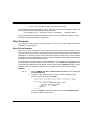
Help Topics
The help can be launched in several ways. The Contents page can be launched by
selecting Help from the CX -Server OPC folder on the Start button. Alternatively, if the
server is running right click the CX logo in the system tray and select Help… from the menu.
The help system provides a standard look-up dialog under the Contents tab showing the
contents of the CX-Server OPC Help file. Double-click on an item to read the associated
information.
Refer to Microsoft Windows documentation for further information on using the Index and Find
features.
About CX-Server OPC
The OPC Server menu includes an About dialog contains essential version number information
and includes details of the version of CX-Server installed that are required for obtaining
technical support. The CX-Server ActiveX Components also include an About dialog containing
essential version number information, which is accessible from their properties menu.
In addition, a brief description of CX-Server OPC and the CX-Automation Suite can be
accessed from the main help contents dialog.
Technical Support
If the installation instructions for this application have been followed, no difficulties should be
encountered.
If a problem occurs, check that it does not relate to a fault outside CX-Server OPC, for instance,
with external components. Check the following:
♦
The PC is working correctly,
Page 9
OMRON
Getting Started with CX-Server OPC
♦ The external system or application is working correctly,
♦ The communications system is set up correctly,
♦ Any errors are cleared in the associated PLCs.
When Customer Services need to be contacted, keep the following details to hand. A clear and
concise description of the problem is required, together with the exact text of any error
messages.
Note:
Use the About dialog to obtain the version number of the application.
Page 10
OMRON
Getting Started with CX-Server OPC
Using the OPC Server
This section introduces the OPC Server application to a new user.
What is OPC?
OPC stands for OLE for Process Control, and is a standard published by the OPC
Foundation. The basic aim of the OPC standard is to allow hardware vendors to produce
software drivers (called OPC Servers) and for software vendors to produce applications (called
OPC Clients) that use a standard method for data interchange. This allows software and
hardware from different vendors to be used together.
The most widely used version of the OPC standard is version 2. This replaces the earlier
version 1 standard.
CX-Server OPC provides an OPC version 2 Server by adding an OPC version 2.05 interface to
the CX-Server runtime used for communication to Omron PLCs. Note that the OPC version
1.0a interface is also supported by the CX-Server OPC Server, but has now been superseded,
and the version 2 interface should be used wherever possible. The CX-Server OPC
Communications Client only uses the version 2 interface. Unless otherwise stated, this
document refers to use with the OPC version 2 standard.
Users of CX-Server OPC, who have existing OPC clients or intend to use the OPC client
functionality included may need some basic understanding of OPC. OPC client developers will
need a complete understanding of OPC, and the interfaces defined. For more information on
OPC, see the OPC Foundation web site at www.opcfoundation.org.
Starting CX OPC Server
To launch the OPC Server:
1, 2, 3…
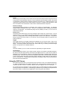
1.
2.
3.
From the Start button, select OPC Server from the section Programs,
Omron, CX-Server OPC.
The server will start. Note the CX logo in the system tray:
Configure the server namespace by clicking the CX logo with the right
mouse button and selecting Select CX-Server Project from the popup
menu.
Page 11
OMRON
Getting Started with CX-Server OPC
i. To open an existing CX-Server Project (.CDM) file:
♦
Click the Open… button and in the Open Project dialog
navigate to the file you wish to open.
♦
When you click the Open button, the full path name of the
selected file will be entered into the Project field.
Caution: When sharing a CDM file with other applications it is important
to realise that any changes that are made to the CDM file may
affect the other applications.
ii. To create a new CX-Server Project (.CDM) file:
4.
5.
♦
Click the New… button and in the Create Project dialog
navigate to the directory in which you wish to create the new
file.
♦
In the File Name field, enter the new file name. When you click
the Save button, the full path name of the new file will be
entered into the Project field.
Click the OK button.
Projects can be edited by clicking the Edit Project… button and then
making the required changes from the Project Editor Dialog. This is a
CX-Server runtime utility – invoke help from within it for details of how to
add and configure PLCs and Points.
Click the OK button to complete the configuration.
The OPC Server is now ready for use by any OPC Client that is compliant with OPC Data
Access version 2 interface.
The CX-Server project file cannot be changed while clients are connected. To select a different
CX-Server project file at a later date, either start the OPC Server manually from the Start button
or if the server is running, select Disconnect Clients and then follow steps 3-5 of the above
procedure.
Tip: You can make the OPC Server start automatically when the PC starts, by copying the
shortcut on the Start button in the CX-Server OPC folder to the Startup folder.
Page 12
OMRON
Getting Started with CX-Server OPC
Using the CX-Server Communications Utilities
CX-Server OPC is supplied with CX-Server. This powerful communications middleware
includes a set of utilities typically used for configuring or monitoring PLC networks, e.g. as part
of a CX-Programmer application. These utilities can also be used with CX-Server OPC. They
are accessed from the “Communications Utilities” submenu that is obtained by right-clicking on
the CX-Server OPC icon which is present in the Windows task bar whenever CX-Server OPC is
running.
Most of these utilities are only available when CX-Server OPC is connected to a PLC (i.e. when
a client is connected), in which case a PLC selection dialog is shown before the utility is
launched. The utility will then automatically connect to the PLC.
The Network Configuration Tool and Performance Monitor Tool are always available. The
Network Configuration Tool is particularly powerful, including options to scan serial ports for
PLCs, or to check communications with a PLC, go online and configure it.
For full details of these utilities consult the CX-Server help files.
Note: If access to these powerful utilities is not required, and no other program that requires
them (e.g. CX -Programmer, CX-Supervisor) is being used on a machine, then they can be
removed by uninstalling CX -Server PLC Tools from the Windows Control Panel.
Fins Gateway Option
CX-Server OPC normally uses the Omron CX-Server Communications software for both device
and point configuration, and also for runtime communications (reading and writing values from a
PLC).
Another Omron product, “Fins Gateway 2003”, also provides communications drivers that can
be used for interfacing to Omron devices. Some users may already have this software installed
on their computers, and may prefer to use it. In addition, a suitable Fins Gateway 2003 installer
is supplied on the CX-Server OPC CD.
The “Server Info” dialog, which can be reached by clicking on the CX-Server OPC Windows
Toolbar icon using the right-mouse button, contains options for configuring communications.
One of these options controls the use of Fins Gateway. If the Fins Gateway option is set, and
Fins Gateway 2003 is present on a computer, then the Fins Gateway drivers will automatically
be used for runtime communication to CS/CJ devices via Ethernet and Controller Link. CXServer will still be used for any non CS/CJ devices, and for any devices that don’t use either
Ethernet or Controller Link. In addition it will still be used for any devices for which dual-network
redundancy is enabled. CX-Server is also always used for configuring the point data.
Note: This is an advanced option. For most applications, communications via the standard
Omron CX-Server communications drivers is ideal, but in some cases performance may be
better or more consistent using the Omron Fins Gateway 2003 drivers. This option allows the
user to choose between the two sets of drivers.
Page 13
OMRON
Getting Started with CX-Server OPC
Using with Third Party OPC Clients
The exact procedure for connecting Third Party OPC Clients to the OPC Server will depend on
the client being used. Consult your OPC Client documentation for full details. However, the
following is a basic overview:
1, 2, 3…
1.
Start and configure the OPC Server as described above.
2.
3.
Start the OPC Client.
Depending on the client, either browse for local OPC servers and select
OMRON.OpenDataServer.1 or type the name directly.
Note: If the client supports browsing for servers, but the server is not
shown, the client may not be fully OPC version 2 compliant.
Create an OPC Group from the client.
4.
5.
Create an OPC Item from the client. If the client supports OPC item
browsing facilities, browse the OPC Server to list the namespace groups
and items to create the OPC Item ID. Otherwise, type the CX-Server
logical name as the OPC Item ID.
Configuring the PC for remote connection
The OPC interface uses a Microsoft technology called DCOM. This allows the OPC client and
OPC server to be seamlessly ‘Distributed’ over a PC network. The OPC Server should be
running on the PC with direct connection to the PLC or PLC network. However, the OPC Client,
or indeed multiple OPC Clients, can be run on different networked PCs and will automatically
read and write data over the PC network. To do this, the PC running the OPC Server must be
correctly configured. For full details of DCOM configuration and security issues see your
Microsoft documentation. The following is a quick guide:
Configuring DCOM
1, 2, 3…
1.
2.
Start DCOMCNFG.EXE e.g. by selecting RUN from the Start button. The
default location on NT is C:\WINNT\SYSTEM32.
View the Default Properties tab (found under the properties section of ‘My
Computer’ in the Computers section of Component Services on XP).
Ensure that the Enable Distributed COM on this computer is checked.
Page 14
OMRON
Getting Started with CX-Server OPC
3.
From the Default Properties tab, configure the Default Authentication
Level to Connect and the Default Impersonation Level to Identify.
Setup the access permissions by either:
a) On the Default Security tab, adding the user to the Access, Launch
and Configuration lists by clicking the Edit Default… button in each
case. The user added should have Administrator rights on the local PC.
If not, it may be necessary to add user groups ‘INTERACTIVE’ and
‘NETWORK’ as well.
b) From the Applications tab, configure the properties for
OpenDataServer and OpcEnum. On the Security tab, add the
required users to each of the Custom Permissions. The users added
should have Administrator rights on the local PC. If not, it may be
necessary to add user groups ‘INTERACTIVE’ and ‘NETWORK’ as
well.
Using CX-Server OPC offline
CX-Server OPC can be used offline (not connected to a PLC). To use this mode of operation
set the “local values” option on the “Server Info” dialog (accessed by right-clicking with the
mouse on the CX-Server OPC icon in the taskbar that is present whenever CX-Server OPC is
running.) The OPC Server should be closed and restarted after setting or unsetting this option
to ensure correct operation.
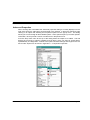
Using CX-Server OPC Device Redundancy Functionality
CX-Server OPC supports device and network redundancy in a way that is transparent to the
OPC client. In order to achieve the full benefits the use of specialist function blocks running in
the PLCs is required. These are usually supplied separately (e.g. on the Installation CD) along
with technical documentation describing their usage. Those documents should be consulted for
detailed technical information on how to set up device redundancy. This section only contains a
brief general overview.
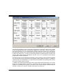
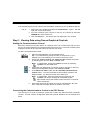
The redundancy is enabled via the “redundant configuration” checkbox on the main “Select CXServer Project” dialog, and a separate configuration file is used to store the redundancy
configuration information. The relevant settings are shown below:
Page 15
OMRON
Getting Started with CX-Server OPC
With device redundancy an OPC client sees a single device connection, which in fact consists
of two physical devices which are effectively duplicates of each other in terms of programs,
data, I/O connectivity etc. In normal operation reading of data occurs from one of the devices,
but data written is sent to both. If the device being read from fails, then a switch is seamlessly
made to the “partner” PLC. In order to ensure that operation proceeds smoothly, and the PLCs
transfer status data between themselves correctly, the use of specialist Function Blocks
(produced by Omron) is required.
For each device in the CX-Server file redundancy can be turned on or off. A partner IP address
and node number can be specified for all suitable (CS/CJ) Ethernet devices. In addition a
“status location” can be specified – this represents the start address of the status data used by
the Omron-supplied function blocks.
In addition to the device-level redundancy there is also network-level redundancy- i.e. for each
device two separate Ethernet connections, associated with two different networks, can be
specified. It is possible for example, to connect to a PLC via two entirely separate Ethernet
networks, with the only common hardware being the PC and the PLC.
Page 16
OMRON
Getting Started with CX-Server OPC
Device and Network redundancy can be used separately, or together (i.e. it is possible to have
up to two network connections to each single or paired device).
The Fins Gateway communications option can be used for device-level redundancy, but will
have no effect where network-level redundancy is in use (i.e. CX-Server will still be used to
communicate to any device that is configured to have access via a second network).
System points that provide access to PLC redundancy function block data include:
PLCNAME_Active – Whether a PLC is currently the active device (boolean)
PLCNAME_Inactive – Whether a PLC is currently the inactive device (boolean)
PLCNAME_ForcedRun – Whether the PLC forced run bit is set
PLCNAME_ProgChangeAlm – Whether the PLC FB “Program Change Alarm” bit is set.
PLCNAME_PartnerFailAlm – Whether the PLC FB “Partner Change Alarm” bit is set.
PLCNAME_Lifecycle – Whether the PLC FB “Lifecycle” bit is set.
PLCNAME_PrimaryNodeNum – PLC FB Primary Node Number
PLCNAME_MakeActive – When set, makes a PLC Active
PLCNAME_MakeInactive – When set, makes a PLC Inactive
PLCNAME_ForceRunPLC – When set, forces a PLC to run
PLCNAME_UseFBInput – Signals that the Function Block Input data should be used
PLCNAME_AutoSwitch – When set, indicates that the server should treat a device as inactive
when communications with it is lost (otherwise the FB Active and Inactive setting will always be
treated as correct – i,e, the redundancy will be under full Function Block control).
PLCNAME_OKConnections – Number of currently valid connections to a device (e.g. in a
system with both device redundancy and network redundancy this value will normally be 4).
Consult the function block documentation for further details of function block operation.
Page 17
OMRON
Getting Started with CX-Server OPC
Predefined System Points
In addition to the redundancy system points described in the section on redundancy, CX-Server
OPC includes several other predefined points which can be used for reading status and
diagnostic information. These points include:
(Note: In all of the points below PLCNAME is replaced with the actual name of the PLC)
PLCNAME_Status – Current PLC Status as an integer – the values correspond to the standard
OPC values and should be displayed in hexadecimal, e.g. 0xC0 (the 0x prefix indicates
hexadecimal, 0xC0 is 192 in decimal) means OPC status OK
(Note: the most common OPC values are “OPC Quality Bad” = 0x00, “OPC Quality Uncertain” =
0x40, “OPC Quality Good” = 0xC0, “OPC Quality Configuration Error” = 0x04, “OPC Quality Not
Connected” = 0x08, “OPC Quality Device Failure” = 0x0C, “OPC Quality Out of Service” =
0x1C. The status text point – see below – will contain a description of the status.)
PLCNAME_StatusText – Current PLC Status (as a string)
PLCNAME_Mode – Current PLC Mode (as an integer, unknown mode = -1 (or 65535 if
displayed as an unsigned value), stop/program mode = 0, run mode = 1, monitor mode = 2)
PLCNAME_Time – Current PLC Time (as a string)
PLCNAME_IsOpen. – Whether PLC has been “opened” for communications (as a boolean)
PLCNAME_Heartbeat – The current “heartbeat” of the communications, in milliseconds. This
value is normally 1000, and a consistently higher value can indicate that communications is
overloaded. Note: Calculation of this value relies on the presence of at least one point that is
being read at a 1-second subscription update rate, otherwise 0 will be returned.
The following diagnostics points are only maintained if communications is being read via Fins
Gateway. (The CX-Server Performance Tool should be used to obtain the corresponding values
when communicating via CX-Server):
PLCNAME_MessageQLen – Number of outstanding comms messages (as an integer)
PLCNAME_TXBytes – Total bytes transmitted
PLCNAME_RXBytes – Total bytes received
PLCNAME_Latency – time in milliseconds between starting to transmit a message and
receiving the last byte of the reply.
PLCNAME_TheoreticalCPS – Number of characters (bytes) expected to be transmitted
PLCNAME_ActualCPS– Total characters (bytes) transmitted in last second
Page 18
OMRON
Getting Started with CX-Server OPC
Controlling CX-Server Input Optimisations
The Omron CX-Server middleware contains optimisations that improve communications
throughput and which are enabled by default. In certain specific circumstances it may be best to
disable the CX-Server i nput optimisations: if a program is running in the PLC which changes a
memory location that is being written by CX-Server soon after the time that CX-Server writes it,
then there is a theoretical risk that the change of value by the PLC program may be missed by
a current subscription to the same location. This situation can also occur if the value written to
the PLC by the PLC program is a constant value, and CX-Server changes it in-between the
writes by the PLC program. (Note: any new attempt to read from device, e.g. a synchronous
read from device, would return the correct value). Disabling the CX-Server input optimisations
will ensure that the correct value is always obtained, but will slow down communications,
although this is unlikely to be noticeable except in the circumstances where there are
subscriptions to large numbers of points that are rapidly changing value.
PLC Opening Option
The “Open all PLCs when first client connects” option does what it says -automatically opens all
PLCs when the first client connects. This means that an attempt is made to communicate with
the PLC. The PLC will be polled thereafter, while open, at the rate of about once a second to
check that it remains online and ready for communications.
If the option is not set, then the PLC will only be opened when an attempt is made to
communicate with it (e.g. a point within it is made active). The PLC will be closed when the last
active point within it is made inactive.
Users should be aware that opening and closing a PLC can be quite inefficient, so in normal
circumstances it is better to leave this option set. In circumstances where some PLCs are
deliberately left unconnected, it may be better to unset the option and to control whether the
PLC is opened or closed by the use of active points within it – as long as one point is active the
PLC will be kept open. Users should also be aware that any direct read of the PLC will also
cause it to be opened, even if no points within it are active, and that it will not be automatically
closed thereafter. It will be left open, awaiting any further direct PLC communications.
String Option
The “Set default (cardinal) type for signed char arrays to string (VT_BSTR)” option is intended
for use with clients which display the default server type for items. The CX-Server signed char
array type is the internal CX-Server data type used for strings, but some clients do not convert
this into a string by default. Setting this option means that CX-Server OPC will inform clients
that the default native (cardinal) type for any points defined as signed char arrays is string
(VT_BSTR). This should ensure that those clients correctly represent the data as a string.
Page 19
OMRON
Getting Started with CX-Server OPC
Silent Mode Option
This option can be used to configure CX-Server OPC to start up hidden (without a splash
screen, and without an icon on the Windows system tray).
Command Line Options
Parameters that can be passed to CX-Server OPC are normally preceded with a hyphen or the
slash symbol /, and include the following:
-Silent – This will force CX-Server OPC to start up hidden (without a splash screen, and without
an icon on the Windows system tray)
-Display – This will force CX-Server OPC to start up visibly (with a splash screen, and with an
icon in the Windows system tray). This option overrides the silent mode option (and the Silent
parameter).
-Persist – If this option is not set then CX-Server OPC will automatically close when the last
client disconnects, otherwise it will continue to run. Use the combination of this option and
Silent cautiously, as CX-Server OPC will then continue running until Windows is shut down.
-RegServer - This is an advanced option, normally used on its own, which, rather than running
CX-Server OPC, simply registers it at the location of the .exe being run, so that it can be
automatically invoked from OPC etc.
These parameters can be passed via the Windows Run command, or added to a Windows icon
shortcut linked to CX-Server OPC.
Page 20
OMRON
Getting Started with CX-Server OPC
Using the OPC Client Components
CX-Server OPC also includes an OPC Client, called Omron OPC Communications
Component and graphical controls that link directly to the communications component. These
are all ActiveX controls allowing data to easily be collected and displayed in either Excel or
Visual Basic. The graphical controls and communication component can of course be used
with any version 2 OPC Server.
Objects Overview
OPC Communications Control
This control provides a seamless interface between the CX-Server OPC host application (Excel,
Visual Basic) and any version 2 compliant OPC Server. Note that the control is only visible
when the host application is in the Design mode.
7 Segment
The 7 segment displays a numerical value in Binary, Decimal or Hexadecimal formats. Leading
zeros and unused segments can be hidden. The colour of the segments and the display
background can be set independently. The 7 Segment cannot be used to set a value.
Data Logging
The Data Logging control provides logging and trending functionality through use of the Data
Log Viewer components currently used by other Omron software packages including
CX-Supervisor and SYS-Config. The control is configured in design-mode to log data items and
is controlled in runtime-mode using script commands. See the on-line help for further details
regarding the script interface.
Display
The Display displays an analogue or text value. The Display only displays a value i.e. you
cannot set a value using this display.
LED Indicator
The LED functions as a coloured on/off indicator. The colour of the indicator and the display
background can be set independently while its shape can be round or square. In the off state,
the chosen indicator colour is dimmed.
Linear Gauge
The Linear Gauge displays an analogue value by filling a rectangle to represent the actual
value as a proportion of its expected maximum. The rectangle can be filled from bottom to top
(like a thermometer) or from left to right (like a progress complete bar). There is also a
configurable scale, enabling intermediate values to be estimated. The Linear gauge will only
display a value, you can not set a value with this gauge.
Page 21
OMRON
Getting Started with CX-Server OPC
Linker
This control gives the ability to link COTS (commercial off the shelf) ActiveX components to any
of the Omron communications controls, e.g. the CX-Server communications control. The control
is configured in design-mode to select the ActiveX component (e.g. a Microsoft Forms V2.0
check box control) to which the control will link at runtime. In runtime mode data will be read
from and written to the selected PLC item and the selected ActiveX component.
Rotational Gauge
The Rotational Gauge displays an analogue value, similar to a speedometer. An indicator
needle rotates according to the value. There is a configurable scale, enabling intermediate
values to be estimated. The Rotational gauge will only displays a value, you can not set a
value with this gauge.
Rotary Knob
The Rotary Knob allows the you to set an analogue value, similar to a volume knob. You can
rotate the knob, e.g. by clicking and dragging the mouse, to set the pointer to a new position.
There is a configurable scale, enabling intermediate values to be estimated. The pointer
always reflects the current value e.g. on start-up, and will change position in response to an
external influence.
Toggle
The Toggle allows you to toggle a Boolean bit between its ‘On’ and ‘Off’ state. This is as a
switch that can be clicked to change its state. The current state is shown by the position of the
switch. The switch position also reflects the current value e.g. on start-up, and will change
position in response to an external influence.
Timer
The timer enables you to run a set of instructions repeatedly at regular intervals.
Thumbwheel
The Thumbwheel provides a set of input controls, similar to a hardware Thumbwheel Switch.
By clicking minus and plus buttons, the various input digits can be set. There are two modes of
operation; Commit and Direct. When the optional Commit button is enabled, digit values may
be edited freely. The PLC will not receive an updated value until the Commit button is pressed.
In direct mode [without the optional Commit button] changes to digit values are sent direct to
the PLC as they occur. Floating point is supported, and integer values can be represented in
both decimal and hexadecimal.
Using the OPC Server
The following sections take you through the steps required to open your selected application,
i.e. Excel or Visual Basic and create a working area. Using the short tutorial you can then
continue and load a number of ActiveX objects, link them together and run a simulation.
As you became more practised in using CX-Server OPC you will find there is usually more then
one way to perform an operation. The following procedures may not always be the quickest but
have been written to show how the application works using the basic features.
Page 22
OMRON
Getting Started with CX-Server OPC
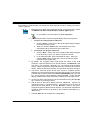
If the ActiveX objects are not visible in the Visual Basic Toolbox they can be added as follows:
1, 2, 3…
1.
2.
3.
Right click in the Toolbox and select the Components… option. This will
open the Components dialog.
Find the CX-Server OPC controls in the list, all of which all start with
OMRON CX, and tick each box.
Click the OK button. The objects are now displayed in the Toolbox.
Step 1: Viewing Data using Omron Graphical Controls
Adding the Communications Control
Before the Graphical Controls objects of CX-Server OPC can communicate with an OPC
Server, the correct data source connections have to be set up for it. This is not necessary if the
Graphical Control will be used stand alone and driven from script.
To add a Communications Control:
1, 2, 3…
1.
2.
Start the host application e.g. Microsoft Excel 97.
Tip: If you intend having a large number of components on your
desktop it is recommended you run Excel in full screen mode.
Ensure the Control Toolbox and CX-Server OPC toolbars are shown
by selecting them from the View, Toolbar menu.
Note:
3.
4.
5.
In Visual Basic, ensure the Toolbox is shown by selecting
Toolbox from the View menu.
Ensure the host application is in design mode for example, in Excel by
clicking the Design Mode button in the Control Toolbox.
In the CX-Server OPC toolbar click the Add OPC Communications
Control button. The Communications Control object is drawn in the
default position - top left hand corner of the work area.
Note: In Visual Basic, select the required component from the
Toolbox and draw a rectangle at the desired position.
Tip: Double clicking the toolbox button inserts the component
with a default size.
Using Drag and Drop the object can now be repositioned in the work
area. Note that the object will not be visible in run mode.
Connecting the Communications Control to an OPC Server
The first step is to create a project file (.OPC file) or select one which has been previously
created. This file contains configuration data and symbolic definitions for the desired OPC
items
Page 23
OMRON
Getting Started with CX-Server OPC
The following procedure takes you through the steps required to load an existing .OPC file or
create a new one.
1, 2, 3…
1.
Right click on the OPC communications control. In the popup menu, select
the OMRON CX OPC Communications Control Object option.
Note:
2.
In Visual Basic, the menu option is called Properties.
In the Communication Control Properties dialog select the Project file:
i.
To open an existing project (.OPC) file:
♦
ii.
Click the Open… button and in the Open Project dialog navigate
to the file you wish to open.
♦ When you click the Open button, the full path name of the
selected file will be entered into the Project field.
To create a new project (.OPC) file:
♦
Click the New… button and in the Create Project dialog navigate
to the directory in which you wish to create the new file.
♦
3.
4.
5.
In the File Name field, enter the desired file name. When you
click the Save button, the full path name of the new file will be
entered into the Project field.
By default, the Computer Name field shows the name of the local
computer. If the OPC Server is on a remote machine, click Show All. This
may take a few moments, depending on your network and operating
system. When complete the Computer Name list now shows all computer
names. Select the required computer, and wait while connection is tested.
The Server name list shows all the OPC version 2 compliant servers
registered on the computer listed in Computer Name field. For the server
included with CX-Server OPC select Omron.OpenDataServer.1 from the
list. The connection can be tested by clicking the Info… button that will
display standard OPC status information collected from the OPC server.
At least one OPC client Groups must now be defined using the Groups
tab. Choose any meaningful name.
6.
Add an Item for the data to display using the Items tab. Choose any
meaningful name e.g. OPCBoilerTemp. Type the Item ID of the item as
defined by the OPC Server or use the Browse… button if the server
supports the optional ‘Browse items’ interface. For the server included with
CX-Server OPC the Item ID is same as the CX-Server Point Name e.g.
“BoilerTemp”.
7.
Click the OK button to complete the configuration.
Page 24
OMRON
Getting Started with CX-Server OPC
The communications control is now ready to connect to the OPC Server, and retrieve data.
This data can be accessed using script commands (see Appendix B), or by adding a Graphical
Component.
Adding a 7 Segment Display
1, 2, 3…
1.
With the host application in design mode, add a 7 Segment control.
2.
Right click on the graphical component and from the popup menu select the
OMRON CX 7 Segment Control Object option.
Note:
3.
In Visual Basic, the menu option is called Properties.
In the component properties dialog select the Data Source tab and enter
the following information:
♦
4.
Server: - Select the name of the communications control to be used. If
only one has been added, it is selected automatically. If the list is
empty then you need to add one first.
♦ Group: - Select the required group. If the appropriate group is not in
the list click the > button and select Add Group….
♦ Item: - Select the point Item. If the appropriate Item is not in the list
click the > button and select Add Item….
Click OK to complete the connection.
Running the Application
Click the Mode button to change to ‘Run’ mode. The communications control
will disappear and will connect to the server. Once connected, the 7 Segment
display will show the current value.
Note: In Visual Basic, click
to switch to run mode, and
to return
to design mode.
Step 2: Inserting Data in Cells
Step 1 shows data in a graphical control, but the data can also be inserted directly into cells
within Excel. This could be useful for further numerical analysis, like averaging or statistical
control.
Note
:
In Visual Basic, there is no concept of cells, but the same technique could be used
to set a Visual Basic variable.
Page 25
OMRON
Getting Started with CX-Server OPC
Assuming Step 1 above has been completed:
1, 2, 3…
1.
Decide when the data should be updated:
i. For the user to control the data update, add a standard Command
Button from the Control Toolbox.
ii.
For the value to constantly update on a regular interval, add the
Omron timer control.
2.
Double click the added object to access the script and add the line:
Cells(1, 1) = OPCComms1.Value(“GroupName”,
"OPCBoilerTemp")
where OPCBoilerTemp is the name of the item to read.
3.
Close the Visual Basic editor, and run the application as shown in Step
1. The cell A1 (that is row 1, column 1) will show the required data.
Step 3: Adding Third Party ActiveX Controls
Step 1 shows data in an Omron graphical control, but the data can used by other ActiveX
controls, like Graphical Control Libraries supplied by other manufacturers, or controls like
Charts or Scroll Bars supplied with Microsoft products.
Assuming Step 1 above has been completed, the following steps show connecting the data to a
standard Scroll Bar:
1, 2, 3…
1.
Add a standard Scroll Bar from the Control Toolbox.
2.
Select and resize the buttons as required then drag and drop the buttons in
the desired position.
3.
Double- click on the scroll bar buttons. This will reposition the cursor in the
code sheet at the following entry.
Private Sub Scrollbar1_Change()
End Sub
Note:
4.
In Visual Basic, the default name for scroll bars is HScroll1 or
VScroll1.
Add the following syntax. The additional command instructs any new Scroll
Bar value to be written to the server.
Private Sub Scrollbar1_Change()
OPCComms1.Value(“GroupName”, “OPCBoilerTemp”) =
Scrollbar1.Value
End Sub
Run the application as shown in Step 1. The communications control will
disappear and the 7 Segment display will show the current value. When you
click on the scroll bar buttons the value is sent to the server. This new value is
then shown on the 7 segment display. Note that the maximum value is limited
Page 26
OMRON
Getting Started with CX-Server OPC
to 100. This is the default value of the scroll bar buttons.
This example shows a control setting a value. Third Party controls can also display values. For
this, the syntax would be (depending on actual control):
ControlName.Value = OPCComms1.Value(“GroupName”, “OPCBoilerTemp”)
This script could also be added to a button or Timer control, as explained in Step 2. Script
functions are described further in Appendix B.
Other Features
The following sections provide a brief overview of some of the more advanced features
available in CX-Server OPC.
Event Driven Routines
Many of the script examples in this manual use asynchronous communications, that is
communications are carried out on demand without synchronisation with the rest of the system.
Asynchronous communications can be easily used to quickly create solutions that are easy to
understand. As a solution grows however, asynchronous communications can prove inefficient
and produce unpredictable updating, which is difficult to debug because multiple scripts may be
demanding the same data at the same time.
The OPC Communications Control provides facilities for synchronous communications, that is
communications and data updating are synchronised. The GetData and StopData script
commands (see Appendix B for full details) control the generation of OnData events on regular
intervals, which can be used to efficiently drive multiple controls, and is easier to debug.
Example:
1, 2, 3…
1.
2.
Add an OMRON CX OPC Communications Control and two standard
Command Buttons.
Double click the communications control to add the following script.
Note the script is in the Event OnData:
Private Sub OPCComms1_OnData(ByVal Group As String,
ByVal Item As String, ByVal Value As Variant, ByVal
BadQuality As Boolean)
If (Item = "OPCBoilerTemp") Then
'Data is from this point
Cells(1, 1) = Value
End If
End Sub
Every time OnData is called with data from the point OPCBoilerTemp
the value is written to the cell A1.
Page 27
OMRON
Getting Started with CX-Server OPC
3.
Double click the Command Buttons to add the following script:
Private Sub CommandButton1_Click()
OPCComms1.GetData "MyGroup", "OPCBoilerTemp"
End Sub
Private Sub CommandButton2_Click()
OPCComms1.StopData "MyGroup", "OPCBoilerTemp”
End Sub
Run the application. Click CommandButton1 to start creating OnData events every second.
Note the cell A1 updating. Click CommandButton2 to stop the updating.
Page 28
OMRON
Getting Started with CX-Server OPC
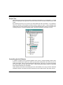
Advanced Properties
When working with Visual Basic the advanced properties dialog is normally displayed on the
right of the work form, although it can be docked in any position. In Excel it is opened by right
clicking on an object and selecting the Properties option from the popup menu. The dialog
allows you to scan through all the available options. Some options require you to enter specific
information, others provide a choice of entries from a drop down menu.
From the drop down menu at the top of the dialog select the object to be edited. This will
display the full range of options available for that object, which can then be viewed either
Alphabetically or Categorised. A full list of the options and their settings and ranges for the CXServer OPC objects can be found in Appendix A – Component Properties.
Page 29
OMRON
Getting Started with CX-Server OPC
Project Tree
Like Explorer the Project Tree provides a graphical representation of you application. In Visual
Basic it is displayed to the right of the work form while in Excel it is shown on the left of the code
sheet.
By expanding the tree you can see all your associated files and work sheets. It is possible to
open any number of work sheets by simply double- clicking on them. Having multiple work
sheets open in this way enables you to copy and paste between them saving you valuable time
rewriting sections of code that already exist, and more importantly are known to work.
Controlling ActiveX Objects
A number of objects can be grouped together such as the 7 segment display and the spin
buttons by selecting the objects you want to group while holding down the ‘Shift’ key as you
select each object. When you have selected all the objects, right click on an object and select
the ‘Group’ option from the drop down menu. Note however that objects must be ungrouped
before their parameters can be edited.
Other drawing commands such as Bring to Front, Send to Back, Cut, Copy, Past etc. follow the
standard windows conventions and are selected from the toolbar and/or drop down menus.
Page 30
OMRON
Getting Started with CX-Server OPC
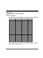
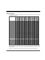
Temperature Controller Support
This version of CX-Server OPC provides access to all the temperature controller devices
supported by CX-Server. For further information regarding the functionality support, see
Appendix C.
Page 31
OMRON
Getting Started with CX-Server OPC
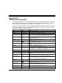
Appendix A
Component Properties
This appendix gives a list of the available properties. Each component supports a selection of
these properties which can be set in design mode by using the properties dialog, or in the run
time by using a Visual Basic script command – for example: - Object1.Value = 10
(Note: The container application may also display additional container-specific properties that
apply to all objects, e.g. Excel provides a parent property. Consult the help for the container
application for details of these properties.)
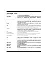
Property Title
Example Values
Description
About
None
Description of t he object.
(Custom)
None
Opens the properties dialog for the object.
(Name)
Object Name
This is the system generated name for the object.
Active
Group and Item
name
This property can be used to get or set OPC group or item active status (to
get or set a group, use an empty name for the item). OPC active status is
more normally set by the EnableGroup and EnableItem methods
Autoload
True
False
Switches the Autoload function On or Off. When set to On the ActiveX
component value will autoload.
True = On, False = Off.
AutoSize
0 to 1
Switches the fonts auto size option on or off.
0 = Off, 1 = On.
BackColour
&H00E0E0E0&
The code determines the background colour of the object. Click the browse
button to display the colour palette.
BorderStyle
0 to 3
The value determines the visual appearance of the border that surrounds the
object.
0 = None, 1 = Raised, 2 = Sunken, 3 = Single_Line
ButtonOn
0 to 1
Determines the default state of the toggle.
0 = Off, Up, Inactive. 1 = On. Down, Active . etc.
ButtonStyle
0 to 6
The value determines the button style.
0 = Toggle Switch, 1 = Colour Button, 2 = In/Out Button, 3 – Rotary Switch
4 = Rocker Switch, 5 = Indicator Button, 6 = Blank Button.
CommsServerName
Comms1 to n
This is the name of associated communications control.
ControlName
CheckBox1
Selects the control name that will be linked to the PLC item at runtime
DatasetName
MyLogFile
Determines the name of the dataset and the file to which the log data will be
saved
DecimalPlaces
2
Number of decimal places for 7 Segment. Only applies when NumberBase =
10
DisplayErrors
True
False
Determines whether or not error messages will be displayed by the
communications control in a message box (set to True), or returned as an
error code to the client applicat ion (set to False), in which case the Visual
Basic Error Object should be used to display the error.
DisplayFont
Arial
This is the system name of the font used for the display. Use the browse
button to display the font dialog. Arial is the default.
DisplayFontColour
&H00000000&
The code determines the colour of the display font. Click the browse button
to display the colour palette.
DisplayFormat
0 – Dec
1 – Hex
2 – Scientific
Determines the format used to display the analogue display information.
0 = Decimal, 1 = Hexadecimal, 2 = Scientific.
DisplayMajorTicks
False
True
Shows or hides the major tick marks of the scale.
True = Show, - False = Hide.
DisplayMajorUnits
False
Shows or hides the major units markers of the scale.
Page 32
OMRON
Getting Started with CX-Server OPC
True
True = Show, False = Hide.
DisplayMinorTicks
False
True
Shows or hides the minor tick marks of the scale.
True = Show, False = Hide.
DisplayMinorUnits
False
True
Shows or hides the minor units markers of the scale.
True = Show, False = Hide.
DisplayType
0 – Analogue
1 – Digital
2 – Text
Determines the type of display.
0 – Analogue: as a numeric value, 1 – Digital: as textual value,
2 – Text: as text.
Enabled
True
False
Switches the object on or off.
True = On, False = Off.
Font
Arial
This is the system name of the font used for the object title. Use the browse
button to display the font dialog. Arial is the default.
FontColour
Height
&H00000000&
141
IndicatorColour
&H00FF0000&
The code determines the colour of the title font. Click the browse button to
display the colour palette.
Sets the overall height of the object in pixels.
The code determines the colour of the indicator. Click the browse button to
display the colour palette.
IsPointvalid
PointName
Returns whether a point is valid Use of this property is described in the script
interface section below
ItemName
Output Flow No1
This is the reference name given to the object.
KnobBorderPercentage
25
This value determines the size of the knob border as a percentage of the
overall size.
KnobColour
&H02C4723E&
The code determines the colour of the knob. Click the browse button to
display the colour palette.
KnobStyle
0 – Integer
1 – Real
Determines how the numerical value of the knob is interpreted
0 = as an integer or 1 = as a real number.
LeadingZ eros
False
True
Turns On or Off the leading zero’s of the display.
False = On, True = Off.
LEDColour
&H00FF0000&
The code determines the default or inactivated colour of the LED indicator.
Click the browse button to display the colour palette.
Left
153
Determines the position of the object from the left hand edge of the work area
in pixels.
ListPoints
PLCName
(optional)
Lists the points in a project (or PLC) Use of this property is described in the
script interface section below
ListPLCs
-
Lists the PLCs in a project (or PLC) Use of this property is described in the
script interface section below
Locked
True
False
Locks the actions of the ActiveX object.
True = Locked, False = Unlocked.
MajorTickInterval
10
Sets the number of major tick intervals.
MaxAngle
180
Determines the length of the arc for rotary gauges. Range ±360 .
MaxCharacters
6
Determines the number of digits to be included in the display.
MaxDecimalPlaces
2
Determines the position of the decimal point in the display.
MaxGaugeValue
50
Sets the maximum value of the gauge.
MaxValue
999.99
Sets the maximum value that can be shown by a display.
MinAngle
0
Determines the length of the arc for rotary gauges. Range ±360 .
MinGaugeAngle
50
Sets the minimum angle of the gauge.
MinGaugeValue
10
Sets the minimum value displayed on the gauge.
MinorTickInterval
2
Sets the number of tick intervals between each major tick interval.
MinValue
-999.99
Sets the minimum value that can be shown by a display.
NumberBase
10
Number Base for 7 Segment e.g. 2 for Binary, 10 for Decimal, 16 for
Hexadecimal
NumberOfDigits
3
Determines the number of digits to be included in the display.
Orientation
0 or 1
Sets the orientation of the gauge – Horizontal or Vertical.
0
0
Page 33
OMRON
Getting Started with CX-Server OPC
0 = Vertical, 1 = Horizontal.
Path
C:\TEMP
Determines the location in which the control will save the log data
PLCName
PLC1
This is the name given to the PLC, not its type.
Precision
2
Number of decimal places for 7 Segment. Only applies when NumBase = 10
PrintObject
True
False
Determines if this ActiveX object will be shown on a printout of the work
sheet.
True = Printed, False = Not printed.
PropertyName
Value
The name of the property in the control to which the PLC item is linked at
runtime
ProjectName
C:\Test1.OPC
The OPC client project file (used by the OPC Client control).Note: This should
not be changed while communications are active –to change the project
name disconnect comms first, then reconnect after setting the new name.
Rollovertime
1
Determines the frequency in hours at which the control will create a new log
file
Round
0 or 1
Determines the shape of the LED indicator. 0 = Square, 1 = Round.
ScaleFont
Arial
This is the system name of the font used for the scale. Use the browse
button to display the font dialog. Arial is the default.
ScaleFontColour
&H00000040&
The code determines the colour of the scale font. Click the browse button to
display the colour palette.
SegmentColour
&H0000C000&
The code determines the colour of the display segments. Click the browse
button to display the colour palette.
ServerComputerName
\\MAINPC
The machine name of the computer on which the OPC Server is running
ServerName
OMRON.OpenData
Server.1
The name of the OPC Server
ServerProjectName
C:\CXSPROJ.CDM
The project file used by the OPC Server (optional, may be blank)
Shadow
True
False
Adds or removes a shadow from the object giving it a raised appearance.
True = Shadow On, False = Shadow Off.
State0Colour
State0Text
&H000000FF&
Text
State1Colour
&H0000FF00&
The code determines the colour of the toggle switch in the 0 state. Click the
browse button to display the colour palette.
This is the text indicating the 0 state of the switch, i.e. Off, Stopped, Halt etc.
The code determines the colour of the toggle switch in the 1 state. Click the
browse button to display the colour palette.
State1Text
Text
This is the text indicating the 1 state of the switch, i.e. On, Running, Start etc.
StateFont
Arial
This is the system name of the font used to display the sate of the switch ro
button. Use the browse button to display the font dialog. Arial is the default.
StateFontColour
&H00000000&
The code determines the colour of the title font. Click the browse button to
display the colour palette.
Title
Text
This is the title that appears in the object.
TitlePosition
0 – Top
1 – Bottom
Determines where title will be placed in the object. Above or below the scale.
Top
230
Determines the position of the object from the top of the work area in pixels.
UnitPostion
0 – Inside
1 – Outside
Positions the dial units inside or outside the scale.
UpdateMethodID
-610
The ID of the method that will invoke the update to the PLC at runtime.
UpdateRate
10
The value sets the frequency, in seconds, at which the data passing to or
from the object is updated.
Value
0
Determines the default value of the ActiveX object. This is typically (although
not always) the default property for a control, so ControlName. = 10 is usually the
same as ControlName.Value = 10
Visible
True
False
Switches the object between visible and invisible in run mode.
True = Visible, False = Invisible.
Width
98.25
Determines the overall width of the object in pixels.
Page 34
OMRON
Getting Started with CX-Server OPC
Appendix B
Script Interface
The Script Interface defines the Visual Basic script interface for the OPC communications
control. (Note: The container application may also display additional container-specific methods
that apply to all objects, e.g. Excel provides a BringToFront method. Consult the help for the
container application for details of these methods.)
Functions
Value
Read
Function for getting and setting an OPC item value.
Function to read the value of an OPC item.
Write
GetData
StopData
Function to write the value of an OPC item.
Function for starting OnData events.
Function for stopping OnData events.
OnData
EnableGroup
EnableItem
Event for receiving notification of a change in data.
Function for enabling (or disabling) active state of an OPC Group
Function for enabling (or disabling) active state of an OPC Item
IsBadQuality
About
Help
Checks whether an item is currently indicating “Bad Quality”
Brings up the about box
Brings up help information
ConnectToServer
Connects to an OPC Server, optionally adding client group and
item definitions to the Server. Note: it is usually not necessary to
call this method, as many other methods automatically call it first if
it is required
Disconnects from the OPC Server. Note: it is usually not
necessary to call this method, as many other methods
automatically call it if it is required
Returns a list of the groups in an OPC project.
Returns the list of items in an OPC group.
Returns the data type of an OPC item
Disconnect
ListGroups
ListItems
VarType
Value
Reads or writes the value of an OPC item.
Example 1 – Reading a value:
intVal = OPCComms1.Value(“MyGroup”, “BoilerTemp”)
In this example, the OPC item ‘BoilerTemp’ in the OPC group called “MyGroup” will be read
from the OPC Server and will be stored in ‘intVal’.
Page 35
OMRON
Getting Started with CX-Server OPC
Example 2 – Writing a value:
OPCComms1.Value(“MyGroup”, “BoilerTemp”) = 50
In this example, the value 50 will be written to the OPC item ‘BoilerTemp’.
Note: ‘Value’ is the default property for all objects, so is assumed if omitted. Therefore, the
following examples are the same:
intVal = OPCComms1.Value(“MyGroup”, “BoilerTemp”)
and
intVal = OPCComms1(“MyGroup”, “BoilerTemp”)
Read
Reads the value of an OPC item.
Example of synchronous read from device:
intVal = OPCComms1.Read(“MyGroup”, “BoilerTemp”, ReadFromDevice)
In this example, the OPC item ‘BoilerTemp’ in the OPC group called “MyGroup” will be read
from the device (e.g. PLC) by the OPC Server and will be stored in ‘intVal’. The script will wait
for the read operation to complete before continuing to execute the next line. This is identical
to the operation of the ‘Value’ method.
Example of synchronous read from cache:
intVal = OPCComms1.Read(“MyGroup”, “BoilerTemp”, ReadFromCache)
In this example, the OPC item ‘BoilerTemp’ in the OPC group called “MyGroup” will be returned
by the OPC Server from its cache, and will be stored in ‘intVal’. The script will wait for the read
operation to complete before continuing to execute the next line. If the value is not available in
the cache (e.g. because the point is not active) then an error (E_FAIL) will be returned and the
quality of the item will be set to bad quality.
Example of synchronous read from cache (or device if cache not available):
intVal = OPCComms1.Read(“MyGroup”, “BoilerTemp”, ReadFromCacheOrDevice)
In this example, the OPC item ‘BoilerTemp’ in the OPC group called “MyGroup” will be returned
by the OPC Server from its cache, and will be stored in ‘intVal’. The script will wait for the read
operation to complete before continuing to execute the next line. If the value is not available in
the cache (e.g. because the point is not active) then the value will be read from device instead.
Example of asynchronous read:
OPCComms1.Read “MyGroup”, “BoilerTemp”, ReadFromDeviceAsync
In this example, the OPC item ‘BoilerTemp’ in the OPC group called “MyGroup” will be read
from the device by the OPC Server. The script will continue to execute the next line
immediately, and when the data is read, it generates an OnData event.
Page 36
OMRON
Getting Started with CX-Server OPC
Write
Writes the value of an OPC item.
Example of synchronous write:
OPCComms1.Write “MyGroup”, “BoilerTemp”, NewValue, WaitUntilComplete
In this example, ‘NewValue’ will be written to the OPC item ‘BoilerTemp’ in the OPC group
called “MyGroup”. The script will wait for the write operation to complete before continuing to
execute the next line. This is identical to the operation of the ‘Value’ method.
Example of asynchronous write:
OPCComms1.Write “MyGroup”, “BoilerTemp”, NewValue, NoWaiting
In this example, ‘NewValue’ will be written to the OPC item ‘BoilerTemp’ in the OPC group
called “MyGroup”. The script will continue to execute the next line immediately.
GetData
Starts asynchronous data reading of the specified OPC item at the group update rate
Example
OPCComms1.GetData “MyGroup”, “MyItem”
In this example, MyItem in MyGroup would be read at the group update rate. Data is then sent
to the OnData routine.
An individual element of a point, defined as an array in a CDM file, can be accessed for reading
or writing values.
Example
Comms1.GetData “MyPLC”, “MyPoint[2]”, nUpdateRate
In this example, the third element of the point MyPoint (defined as plc1/DM500/10/USH) can
now be accessed as MyPoint[2]. By default, if the array element is not specified, then the
whole point (whole array of elements) is manipulated.
By using the ‘OnChange’ command as the forth parameter, the GetData method will only return
points when they change.
Example
Comms1.GetData “MyPLC”, “MyPoint”, nUpdateRate, OnChange
OnChange is of type ‘UpdateSetting’. By default, the UpdateSetting is set to Continuous, to
remain compatible with previous versions.
Page 37
OMRON
Getting Started with CX-Server OPC
StopData
Stops asynchronous data reading of the specified OPC item
Example
OPCComms1.StopData “MyGroup”, “MyItem”
In this example, the asynchronous reading of MyItem in MyGroup would be stopped.
OnData
This event is sent back to the container (e.g. Excel) when data has changed. This is either data
started by calling GetData, or by calling Read or Write in asynchronous mode.
Example
Private Sub OPCComms1_OnData(ByVal Group As String, ByVal
Item As String, ByVal Value As Variant,
ByVal BadQuality as Boolean)
TextBox1 = Item
Segment1 = Value
End Sub
In this example, the CX-Server 7 Segment component is set to the value of the point and a text
box is set to display the name of the item.
If BadQuality is set to True then the value may be inaccurate e.g. from a device which has been
disconnected.
The OnData routine can be enhanced to include logical expressions on the incoming Item
name and then update the correct graphical object etc. for example:
Private Sub OPCComms1_OnData(ByVal Group As String,
ByVal Item As String, ByVal Value As
Variant, ByVal BadQuality as Boolean)
If Item = “MyItem” then
Segment1 = Value
Else if Item = “MyOtherItem” then
Cells(1,1) = Value
End if
End Sub
EnableGroup
Enables (or disables) the active state of the specified OPC group
Examples
OPCComms1.EnableGroup “MyGroup1”, True
OPCComms1.EnableGroup “MyGroup2”, False
In the first example, the group MyGroup1 would be made active. In the second example
MyGroup2 would be made inactive (stopping communication and subscription callbacks)
Page 38
OMRON
Getting Started with CX-Server OPC
EnableItem
Enables (or disables) the active state of the specified OPC item
Examples
OPCComms1.EnableItem “MyGroup”, “MyItem1”, True
OPCComms1.EnableItem “MyGroup”, “MyItem2”, False
In the first example, the item Myitem1 would be made active. In the second example MyItem2
would be made inactive (stopping communication and subscription callbacks)
IsBadQuality
Checks if an item is currently indicating “Bad Quality”.
Example
bBad = OPCComms1.IsBadQuality(“MyGroup”,“MyItem”)
The boolean variable bBad is set True if the item “MyItem” is indicating “Bad Quality” (e.g. the
associated PLC is disconnected).
AboutBox
Brings up the About Box.
Example
OPCComms1.AboutBox
Help
Brings up the Help information.
Example
OPCComms1.Help
ConnectToServer
Connects to an OPC Server, optionally adding client group and item definitions to the Server.
Note: it is usually not necessary to call this method, as many other methods automatically call it
first if it is required.
Example
OPCComms1.ConnectToServer(True) ‘ connects and informs server of groups and items
Page 39
OMRON
Getting Started with CX-Server OPC
Disconnect
Disconnects from the OPC Server. Note: it is usually not necessary to call this method, as many
other methods automatically call it if it is required.
Example
OPCComms1.Disconnect
ListGroups
Returns a list of the groups in an OPC project
Examples
Dim A as Variant
A = OPCComms.ListGroups
For Count = 1 To UBound(A)
ComboBox1.AddItem (A(Count))
Next Count
This example fills a combo box with the names of groups in the current project.
VBScript (CX-Supervisor) Example
Dim arrayOfGroups
Dim nUbound, nLbound
arrayOfGroups = Comms1.ListGroups
nLbound = LBound(arrayOfGroups)
nUbound = UBound(arrayOfGroups)
For Count = nLbound To nUbound
‘Do something with list here
Next
ListItems
Returns a list of the items in an OPC group
Example 1
Dim v as Variant
v = Comms1.ListItems(“Group1”)
Page 40
OMRON
Getting Started with CX-Server OPC
Example 2
Dim A as Variant
A = Comms1.ListItems(ComboBox1.Text)
For Count = 1 To UBound(A)
ComboBox2.AddItem (A(Count))
Next Count
The example above fills ComboBox2 with the names of points in the group shown in
ComboBox1.
VBScript (CX-Supervisor) Example
Dim arrayOfItems
Dim nUbound, nLbound
arrayOfItems = Comms1.ListItems(sGroup)
nLbound = LBound(arrayOfItems)
nUbound = UBound(arrayOfItems)
For Count = 1 To UBound(arrayOfItems)
‘Do something with items list here
Next
VarType
Returns the data type of an OPC variable as a variant containing a long value that can be compared
against the standard Visual Basic data types (i.e. vbArray, vbBoolean, vbByte, vbChar, vbCurrency,
vbDate, vbDecimal, vbDouble, vbEmpty, vbInteger, vbLong, vbNull, vbObject, vbSingle, vbString,
vbUserDefinedType and vbVariant). See Visual Basic (or VBScript) help for more information on
these data types.
Example
Dim v as variant
v = OPCComms1.VarType("Group1", "Item1")
‘ the returned data type v can now be compared with standard VB data types
Page 41
OMRON
Getting Started with CX-Server OPC
Appendix C
Temperature Controller Support
Parameter support
The following table outlines the temperature controller points available from the CX-Server
points editor. Cross-reference this information with the support offered by your specified device.
Word Addressing
Bit Addressing
Read/Write
SETPOINT
PROPORTIONAL
INTEGRAL
DERIVATIVE
OUTPUT
LOWER_LIMIT
UPPER_LIMIT
PROCESS
STRENGTH
SCALE1
SCALE2
ALARM
SHIFT
SHIFT_LOWER
√
√
√
√
√
√
√
√
√
√
√
√
√
√
X
X
X
X
X
X
X
X
X
X
X
√
√
√
√
X
X
X
X
√
√
√
√
√
√
√
√
√
SHIFT_UPPER
BURNOUT
HEATER
ALARM1
ALARM2
ALARM3
COOLING
DEADBAND
VALVE
√
√
√
√
√
√
----
√
√
X
√
√
X
√
√
√
----
√
√
√
----
To access these values via the CX-Lite component add the appropriate temperature controller device.
Add a point using the value from the Data Location column in the table above. You can then access
this information as you would with any point.
Page 42
OMRON
Getting Started with CX-Server OPC
Device support
E5AF-A
E5AF-AH
E5EF-A
E5EF-AH
E5EF-BA
E5EF-BAH
E5AX-A
E5Ax-AH
E5AX-D
E5AX-LA
E5AX-MA
E5AX-PRR
E5AX-V
E5AJ-A
E5EJ-A
E5AK-AA
E5AK-PRR
The following table outlines the temperature controller points available for each of the devices
supported by CX-Server.
SETPOINT
√
√
√
√
√
√
√
√
√
√
√
√
√
√
√
√
√
PROPORTIONAL
√
√
√
√
√
√
√
√
√
√
√
√
√
√
√
√
√
INTEGRAL
√
√
√
√
√
√
√
√
√
√
√
√
√
√
√
√
√
DERIVATIVE
√
√
√
√
√
√
√
√
√
√
√
√
√
√
√
√
√
OUTPUT
√
√
√
√
√
√
√
√
√
√
√
√
√
√
√
√
√
LOWER_LIMIT
√
√
√
√
√
√
√
√
√
√
√
√
√
√
√
√
√
UPPER_LIMIT
√
√
√
√
√
√
√
√
√
√
√
√
√
√
√
√
√
PROCESS
√
√
√
√
√
√
√
√
√
√
√
√
√
√
√
√
√
STRENGTH
√
√
√
√
√
√
--
--
--
--
--
--
--
√
√
--
--
SCALE1
√
√
√
√
√
√
--
--
--
--
--
--
--
√
√
--
--
SCALE2
√
√
√
√
√
√
--
--
--
--
--
--
--
√
√
--
--
ALARM
√
√
√
√
√
√
√
√
√
√
√
√
√
--
--
--
--
SHIFT
√
√
√
√
√
√
√
√
√
√
√
√
√
√
√
--
--
SHIFT_LOWER
--
--
--
--
--
--
--
--
--
--
--
--
--
--
--
√
√
SHIFT_UPPER
--
--
--
--
--
--
--
--
--
--
--
--
--
--
--
√
√
BURNOUT
--
√
--
√
--
√
--
√
--
--
--
--
--
√
√
√
√
HEATER
--
√
--
√
--
√
--
√
--
--
--
--
--
√
√
√
√
ALARM1
--
--
--
--
--
--
--
--
--
--
--
--
--
√
√
√
√
ALARM2
--
--
--
--
--
--
--
--
--
--
--
--
--
√
√
√
√
ALARM3
--
--
--
--
--
--
--
--
--
--
--
--
--
--
--
√
√
COOLING
--
--
--
--
--
--
--
--
--
--
--
--
--
--
--
√
√
DEADBAND
--
--
--
--
--
--
--
--
--
--
--
--
--
--
--
√
√
VALVE
--
--
--
--
--
--
--
--
--
--
--
--
--
--
--
√
√
In addition to the previous table, a special value of PARMxx can be used to refer to any E5AK
parameter, where xx is replaced by a number that corresponds to the number of the parameter
given in the E5AK manual. For example, the special address PARM45 would refer to the 'SP
ramp set value'.
Refer to the Temperature Controller manual for descriptions of each special address.
Page 43
OMRON
Getting Started with CX-Server OPC
Glossary of Terms
ActiveX
Application
Communications Driver
Event
A component technology developed by Microsoft allowing components
to communicate with applications.
A software program that accomplishes a specific task. Examples of
applications are CX-Supervisor, CX-Programmer, CX-Server,
Microsoft Word and Microsoft Excel
The relevant communications management system for OMRON PLCs
in conjunction with Microsoft Windows, providing facilities for other
CX Automation Suite software to maintain PLC device and address
information and to communicate with OMRON PLCs and their
supported network types.
User action, e.g. mouse click or System action, e.g. timer tick which
may cause a script to execute.
GUI
Graphical User Interface. Part of a program that interacts with the user
and takes full advantage of the graphics displays of computers. A GUI
employs pull-down menus and dialog boxes for ease of use.
I/O type
Input / Output type. An attribute of a point that defines the origin and
destination of the data for that point. The data for a point can
originate (be input from) and is destined (is output to) to the internal
computer memory, a PLC or a target application
Pictorial representations of computer resources and functions
A spreadsheet application.
Icon
Microsoft Excel
Microsoft Windows
Microsoft Word
The most common operating system used by Personal Computers.
CX-Server OPC will run only under Microsoft Windows.
A word processing application.
OLE
Object Linking and Embedding.
Used to transfer and share
information between Microsoft Windows based applications and
accessories.
OPC
Abbreviation for OLE for Process Control. Open standard for the
exchange of data between OPC Servers and OPC Clients used within
the process control industry.
OPC Client
A software application that uses OPC interfaces to exchange data
with an OPC Server.
A collection of OPC Items.
OPC Group
OPC Item
OPC Server
PC
A single piece of data e.g. a PLC memory area stored with an OPC
Server.
A software application that uses OPC interfaces to provide data to
OPC Clients.
Abbreviation for Personal Computer.
Page 44
OMRON
Getting Started with CX-Server OPC
Pixel
A single displayable point on the screen from which a displayed image
is constructed. The screen resolution of the computer’s Visual Display
Unit (VDU) is defined by the number of pixels across and the number
of pixels down (e.g. 1024 x 768).
PLC
Point
Abbreviation for Programmable Logic Controller.
A point is used to hold a value of a predefined type - Boolean, Integer,
Text, etc. The contents of a point may be controlled by an object or
I/O mechanism such as DDE. The contents of a point may control the
action or appearance of an object, or be used for output via an I/O
mechanism.
SVGA mode
A mode of video display that provides 800 × 600 pixel resolution (or
higher) with 16 or more colours and is supported on Super Video
Graphics Adapter systems.
Windows Desktop
An integral part of Microsoft Windowsthat allows Microsoft Windows
based applications to be started from icons and for all applications
to be organised.
Page 45
OMRON
Getting Started with CX-Server OPC
Index
A
I
About CX-Server OPC · 9
About this Manual · 6
ActiveX Objects
7 Segment · 21
Display · 21
LED Indicator · 21
Linear Gauge · 21
OPC Communications · 21
Rotary Knob · 22
Rotational Gauge · 22
Timer · 22
Toggle · 22
Adding a 7 Segment Display · 25
Adding the Communication Control · 23
Adding Third Party ActiveX Controls · 26
Advanced Properties · 29
Inserting Data in Cells · 25
Installing/Uninstalling CX-Server OPC · 8
C
Component Properties · 32
Configuring server for remote connection · 14
Connecting to an OPC Server · 23
Controlling ActiveX Objects · 30, 31
O
Objects Overview · 21
OPC
Foundation web site · 11
What is it? · 11
OPC Server
Configuring for remote connection · 14
Starting · 11
Using Third Party OPC Clients · 13, 14, 15, 18, 19,
20
Operating Systems · 7
Other Features · 27
Advanced Properties · 29
Controlling ActiveX Objects · 30, 31
Event Driven Routines · 27
The Project Tree · 30
P
Project Tree · 30
E
Event Driven Routines · 27
R
Running an Application · 25
G
Getting Started with CX-Server OPC · 6
Glossary of Terms · 44
H
Hardware Requirements · 7
Operating Systems · 7
Help Topics · 9
S
Script Interface · 35
Functions · 35
Script Interface Functions
GetData · 37
ListPLCs · 40
ListPoints · 40, 41
OnData · 38
StopData · 38
TypeName · 39, 40
Starting CX OPC Server · 11
System Requirements · 7
Page 46
OMRON
Hardware Requirements · 7
T
Technical Support · 9
The Help System, and How to access it · 9
Tutorial Step 1 Viewing Data using Omron
Graphical Control · 23
Tutorial Step 2 Inserting Data in Cells · 25
Tutorial Step 3 Adding Third Party ActiveX
Controls · 26
Getting Started with CX-Server OPC
Using the OPC Server · 11
Using Third Party OPC Clients · 13, 14, 15, 18, 19,
20
V
Viewing Data using Omron Graphical Control · 23
W
What is OPC? · 11
U
Using the OPC Client components · 21
Page 47