1
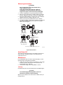
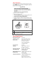
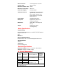
®
360
Leakage Current Clamp Meter
Instruction Sheet
Safety Information
XW Read First: Safety Information
To avoid shock or personal injury, ensure safe
operation and service of the Leakage Current Clamp
Meter (“Clamp Meter”), follow these instructions:
•
•
•
•
•
•
•
•
•
•
•
•
•
Read the operating instructions before use and
follow all safety instructions.
Use the Clamp Meter only as specified in the
operating instructions otherwise the
instrument’s safety features may not protect
you.
Adhere to local and national safety codes.
Individual protective equipment must be used
to prevent shock and arc blast injury where
hazardous live conductors are exposed.
Before each use, inspect the Clamp Meter. Look
for cracks or missing portions of the clamp
housing. Also look for loose or weakened
components. Pay particular attention to the
insulation surrounding the jaws.
Disconnect the Clamp Meter from measurable
conductors under test before opening the case
to replace the battery.
Avoid using the instrument if it has been
exposed to rain or moisture or if your hands are
wet.
Do not use the instrument in an atmosphere
where flammable or explosive gas is present.
Do not use the Clamp Meter near noise-emitting
equipment or where there may be sudden
changes in temperature. Otherwise the Clamp
Meter may produce unstable readings or errors.
Never use the Clamp Meter on a circuit with
voltages greater than 300 V CAT III.
CAT III equipment is designed to protect against
transients in equipment in fixed-equipment
installations, such as distribution panels,
feeders and short branch circuits, and lighting
systems in large buildings.
Use extreme caution when working around bare
conductors or bus bars. Contact with the
conductor could result in electric shock.
Use caution when working with voltages above
60 V dc or 30 V ac. Such voltages pose a shock
hazard.
Do not leave the Clamp Meter exposed to direct
sunlight or in a hot or humid location for any
prolonged period of time.
Keep fingers behind the tactile barrier. See
Figure 1.
PN 2726405
October 2006
© 2006 Fluke Corporation, All rights reserved. Printed in Japan.
All product names are trademarks of their respective companies.
Symbols
Table 1. Symbols
Symbol
Explanation
T
Product is protected by double insulation.
W
Risk of Danger. Important information. See Instruction
Sheet.
X
Hazardous voltage
B
Alternating Current
F
Direct Current
J
,
Earth
~
Do not dispose of this product as unsorted municipal
waste. Contact Fluke or a qualified recycler for disposal.
P
Conforms to relevant European Union directives
May be used on hazardous live conductors
M
Battery
Components
A
B
F
C
E
AUTO POWER OFF
D
POWER
G
H
epq001.eps
Item
Explanation
A
Place fingers behind the Tactile Barrier
B
The Jaw is a precision sensor for detecting current
C
Use the mA/A Selector Switch to choose the range of
ac current (either mA or A) to be measured
D
The Display shows the measured value (digital reading
or bargraph), unit, function, and low-battery symbol
E
Open and close the jaw with the Open/Close Lever
F
The Data Hold Switch retains the measured data on
the display. If pressed, D • H appears and the data is
retained. If pressed again, data hold is canceled and
D • H disappears.
G
Press the Power Button to turn on Clamp Meter power
H
Battery Housing holds the battery
Figure 1. The 360 Clamp Meter
Measuring Instructions
W Caution
Do not subject the jaw to unreasonably strong
shock, vibration, or force.
If dust gets into the top of the jaws, remove it
immediately. Do not close the jaws when dust is
trapped in its joints as the sensor may be damaged.
3.
4.
5.
Turn the Clamp Meter on by pressing the power button.
Open the jaws and insert the conductor under test through
the jaws, making sure the tops of the jaws are tightly shut.
Once the reading stabilizes, read the value. Use the DATA
HOLD function if the reading is difficult to read.
Make sure the jaws are perpendicular to the conductor.
For optimal readings, make sure the conductor is positioned
between the alignment marks on the jaws of the Clamp
Meter. Refer to Figure 2.
(3)
Load
(1)
Load
1.
2.
Single-Phase
Two-Wire Circuit
Grounding Wire
• Example of Load Current
Measurement
Load
Load
(2)
Single-Phase ThreeWire or Three-Phase
Three-Wire Circuit
Insert only one of the wires through the jaws.
epq002.eps
Figure 2. Measurements
Auto Power Off
The instrument automatically turns off 10 minutes after the last
switch operation. A beeper sounds 15 seconds before the
automatic power off.
Maintenance
If the Clamp Meter does not work or perform properly, use the
following steps to help isolate the problem:
1.
2.
Inspect the jaw mating surface for cleanliness. If any foreign
material is present, the jaw will not close properly and
measurement errors will result.
Verify that the range on the Clamp Meter is correct.
Cleaning
Periodically wipe the case with a damp cloth and mild detergent.
W Caution
To avoid damaging the Clamp Meter, do not use
abrasives or solvents to clean the clamp.
Open the jaws and blow air to remove dust or debris at the jaw
mating surfaces.
Battery Replacement
If battery voltage drops below the operating voltage, the battery
symbol (M) appears on the display. If this happens, replace the
battery as soon as possible.
XW Warning
There is risk of electric shock during battery
replacement. Always remove the Clamp Meter from
measurable conductors under test before replacing
the battery.
Always use the correct replacement battery.
To replace the battery, see Figure 3:
1.
2.
3.
4.
5.
Make sure the power is off.
Place the Clamp Meter on its face and turn the battery cover
counter clockwise using a Phillips screwdriver.
Remove the cover and the installed battery.
Replace the battery, making sure that the polarity is correct.
Reinstall the battery cover, turn it clockwise and reinstall the
screw.
A
B
epq003.eps
A
Insert the battery ensuring the polarity is correct.
B
Close the battery cover, aligning the arrow’s tail with the
dot and then turn clockwise
Figure 3. Changing the Battery
General Specifications
Measurement functions
AC current
Additional functions
Data hold and Auto power-off
Display (LCD)
Digital reading : 3200 counts
Bar Graph: 32 segments
“OL” over-range indication
Low-battery symbol
Range Selection
Automatic
Sampling
Digital reading: 2 times/sec
Bar graph: 12 times/sec
Operating temperature
and humidity range
0 to 50 °C, with a maximum
humidity of 80 % RH
(no condensation)
Storage temperature and
humidity range
-20 to 60 °C, with humidity range
20 to 70 % RH
(no condensation)
Temperature Coefficient
± 0.05 % of measuring range/°C
(< 18 °C or > 28 °C).
Measuring range: 0 to 50 A
0.0005 % typical value (in terms
Effect of external
magnetic fields
of the magnitude of current in
adjacent wires)
Maximum conductor Size
40 mm
Maximum circuit voltage
300 V rms
Power Consumption
6 mW maximum
Automatic Power off
Automatically turns off the power
approximately 10 minutes after
the last switch operation. The
beeper will turn on 15 seconds
before power off.
Power Supply
CR2032 lithium battery
Battery Life
Approximately 90 hours of
continuous operation
Dimensions
70 mm (W) x 176 mm (H) x 25
mm (D)
Weight
Approximately 200 g
(including battery)
Safety Specifications
Category Rating
CAT III 300 V per IEC/EN61010-1, and 61010-2-032 Pollution
Degree 2, indoor use
EMC
EN61326-1
Effect of Radiated Immunity
Rated accuracy +4.0 % in an electromagnetic field of 3 v/m.
Operating Altitude
2000 m
Accessories
C75 soft carrying case
Electrical Specifications
Reference Conditions: 23 ± 5 °C and 80 % RH maximum
Accuracy: ±(percent of reading + digit)
AC Current Measurement
Range
Resolution
Accuracy (50/60 Hz)
3 mA
0.001 mA
30 mA
0.01 mA
30 A
0.01 A
0 to 50 A: 1 % + 5
60 A
0.1 A
50 to 60 A: 5 % + 5
Maximum
Allowable
Current
1% + 5
60 A rms
Zero correction: Fractions smaller than approximately 0.01 mA
are calibrated to zero.
Contacting Fluke
To contact Fluke, call one of the following telephone numbers:
USA: 1-888-44-FLUKE (1-888-443-5853)
Canada: 1-800-36-FLUKE (1-800-363-5853)
Europe: +31 402-675-200
Japan: +81-3-3434-0181
Singapore: +65-738-5655
Anywhere in the world: +1-425-446-5500
USA Service: 1-888-99-FLUKE (1-888-993-5853)
Or, visit Fluke's Web site at www.fluke.com.
To register your product, visit register.fluke.com
LIMITED WARRANTY AND LIMITATION OF LIABILITY
This Fluke product will be free from defects in material and workmanship
for one year from the date of purchase. This warranty does not cover
fuses, disposable batteries, or damage from accident, neglect, misuse,
alteration, contamination, or abnormal conditions of operation or
handling. Resellers are not authorized to extend any other warranty on
Fluke’s behalf. To obtain service during the warranty period, contact your
nearest Fluke authorized service center to obtain return authorization
information, then send the product to that Service Center with a
description of the problem.
THIS WARRANTY IS YOUR ONLY REMEDY. NO OTHER
WARRANTIES, SUCH AS FITNESS FOR A PARTICULAR PURPOSE,
ARE EXPRESSED OR IMPLIED. FLUKE IS NOT LIABLE FOR ANY
SPECIAL, INDIRECT, INCIDENTAL OR CONSEQUENTIAL DAMAGES
OR LOSSES, ARISING FROM ANY CAUSE OR THEORY. Since some
states or countries do not allow the exclusion or limitation of an implied
warranty or of incidental or consequential damages, this limitation of
liability may not apply to you.
Fluke Corporation
P.O. Box 9090
Everett, WA 98206-9090
U.S.A.
11/99
Fluke Europe B.V.
P.O. Box 1186
5602 BD Eindhoven
The Netherlands