1
User’s
Manual
Models SR10001/SR10002/SR10003/SR10004/
SR10006
SR10000
Communication Interface
IM 04P03B01-17E
Yokogawa Electric Corporation
1st Edition
Foreword
Thank you for purchasing the YOKOGAWA SR10000 (hereafter referred to as the
recorder).
This user’s manual describes the functions of the Ethernet interface and the RS-422A/
485 communication interface. To ensure correct use, please read this manual
thoroughly before beginning operation. After reading the manual, keep it in a convenient
location for quick reference whenever a question arises during operation.
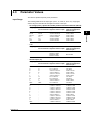
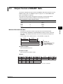
The following three manuals, including this one, are provided as manuals for the
recorder. Please read all of them.
• Paper Manual
Manual Title
Manual No.
Description
SR10000
Operation Guide
IM 04P03B01-02E
Explains the basic operations of the SR10000.
It is also provided in the CD.
• Electronic Manuals Provided on the Accompanying CD-ROM
Manual Title
Manual No.
Description
SR10000
User’s Manual
IM 04P03B01-01E
Explains the convenient functions and
procedures of the SR10000.
SR10000
Operation Guide
IM 04P03B01-02E
This is the electronic version of the paper
manual.
SR10000
IM 04P03B01-17E
Communication Interface
User’s Manual
This manual. Explains the functions of the
Ethernet interface and the RS-422A/485
communication interface.
Notes
• The contents of this manual are subject to change without prior notice as a result of
continuing improvements to the instrument’s performance and functions. The figures
given in this manual may differ from those that actually appear on your screen.
• Every effort has been made in the preparation of this manual to ensure the accuracy
of its contents. However, should you have any questions or find any errors, please
contact your nearest YOKOGAWA dealer.
• Copying or reproducing all or any part of the contents of this manual without the
permission of Yokogawa Electric Corporation is strictly prohibited.
• The TCP/IP software of this product and the document concerning the TCP/IP software
have been developed/created by YOKOGAWA based on the BSD Networking Software,
Release 1 that has been licensed from the University of California.
Trademarks
• All the brands or names of Yokogawa Electric’s products used in this manual are
either trademarks or registered trademarks of Yokogawa Electric Corporation.
• Microsoft, MS-DOS, Windows, Windows NT, and Windows XP are either registered
trademarks or trademarks of Microsoft Corporation in the United States and/or other
countries.
• Adobe, Acrobat, and PostScript are trademarks of Adobe Systems incorporated.
• For purposes of this manual, the TM and ® symbols do not accompany their
respective trademark names or registered trademark names.
• Other company and product names are trademarks or registered trademarks of their
respective holders.
Revisions
• 1st Edition
February, 2006
1st Edition : February 2006 (YK)
All Rights Reserved, Copyright © 2006, Yokogawa Electric Corporation
IM 04P03B01-17E
i
How to Use This Manual
Structure of the Manual
This user’s manual consists of the following sections.
This manual does not cover error messages. See the SR10000 User’s Manual
(IM04P03B01-01E).
Chapter 1 Overview of the Communication Functions
Gives an overview of the communication functions.
Chapter 2 Using the Ethernet Interface (/C7 Option)
Explains the specifications of the Ethernet interface and how to use the interface.
Chapter 3 Using the RS-422A/485 Communication Interface (/C3 Option)
Explains the specifications of the RS-422A/485 communication interface and how to use the
interface.
Chapter 4 Commands
Explains each command that is available.
Chapter 5 Responses
Explains the responses that the recorder returns and the output format of the setup data and
measured data.
Chapter 6 Status Information
Explains the registers that indicate the recorder statuses.
Appendix
Provides an ASCII character code table, flow charts for outputting data from the recorder, and
login procedure. Describes the difference of communication commands between SR10000
and SR1000.
Index
Index of contents.
ii
IM 04P03B01-17E
How to Use This Manual
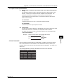
Conventions Used in This Manual
• Unit
• k: Denotes 1000. Example: 5 kg, 100 kHz
• K: Denotes 1024. Example: 640 KB
• Note
The following markings are used in this manual.
Improper handling or use can lead to injury to the user or damage
to the instrument. This symbol appears on the instrument to
indicate that the user must refer to the user’s manual for special
instructions. The same symbol appears in the corresponding place
in the user’s manual to identify those instructions. In the manual,
the symbol is used in conjunction with the word “WARNING” or
“CAUTION.”
WARNING
Calls attention to actions or conditions that could cause serious or
fatal injury to the user, and precautions that can be taken to prevent
such occurrences.
CAUTION
Calls attentions to actions or conditions that could cause light injury
to the user or damage to the instrument or user’s data, and
precautions that can be taken to prevent such occurrences.
Note
Calls attention to information that is important for proper operation
of the instrument.
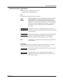
• Subheadings
On pages that describe the operating procedures in Chapter 2 and 3, the following
symbols are used to distinguish the procedures from their explanations.
Explanation
Procedure
This subsection describes the setup parameters and the limitations
on the procedures.
Follow the numbered steps. All procedures are written with
inexperienced users in mind; depending on the operation, not all
steps need to be taken.
IM 04P03B01-17E
iii
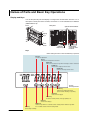
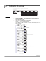
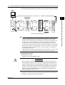
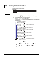
Names of Parts and Basic Key Operations
Display and Keys
You use the panel keys and the display to configure the communication functions. For a
description of other parts of the recorder, see section 3.1 in the SR10000 User’s Manual
(IM04P03B01-01E).
Front
Rear panel
Optional terminal block
Display
Keys
Power
switch
Indicator
Ethernet port
RS-422A/485
communication
terminals
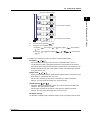
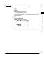
Keys
<When setting functions or when the FUNC key is pressed>
ESC key
Cancels the operation.
UP key
Switches the setup item or the value.
RIGHT key
Moves the cursor to the right when entering a value or character.
DOWN key
Switches the setup item or the value.
ENTER key
Confirms the setup item or value.
RCD
ALM
<During
normal operation>
CH UP key
Switches the displayed channel.
(when manual switching is specified)
FEED key
Feeds the chart paper.
FUNC key
Executes manual printout, message printout, etc.
DISP key
Switches the display.
MENU key
Hold this key down for 3 seconds to enter Setting mode. Hold this key down
for 3 seconds also to exit from Setting mode.
RCD key
Starts/stops recording.
iv
IM 04P03B01-17E
1
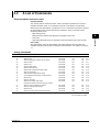
Contents
Foreword ......................................................................................................................................... i
How to Use This Manual ................................................................................................................. ii
Names of Parts and Basic Key Operations .................................................................................... iv
Chapter 1 Overview of the Communication Functions
1.1
1.2
Communication Functions Using the Ethernet Interface (/C7 Option) ..................... 1-1
Functional Construction ................................................................................................... 1-1
Setting/Measurement Server ........................................................................................... 1-1
Maintenance/Test Server ................................................................................................. 1-2
Instrument Information Server ......................................................................................... 1-2
Other Functions ............................................................................................................... 1-2
Communication Functions Using the RS-422A/485 Communication Interface (/C3
Option) ............................................................................................................................ 1-3
Functional Construction ................................................................................................... 1-3
Setting/Measurement Server ........................................................................................... 1-3
Modbus Slave .................................................................................................................. 1-3
2
3
4
5
6
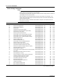
Chapter 2 Using the Ethernet Interface (/C7 Option)
2.1
2.2
2.3
2.4
2.5
2.6
Ethernet Interface Specifications ................................................................................. 2-1
Basic Specifications ......................................................................................................... 2-1
The Maximum Number of Simultaneous Connections and the Number of Simultaneous
Use ................................................................................................................................... 2-1
Connecting the Ethernet Interface ............................................................................... 2-2
When Connecting Only the Recorder and a PC .............................................................. 2-2
When Connecting to a Preexisting Network .................................................................... 2-2
Configuring the Ethernet Interface ............................................................................... 2-3
Setup Items and Setup Procedure ................................................................................... 2-3
Connection Example with a PC ....................................................................................... 2-3
Setting the IP Address ................................................................................................... 2-4
Checking the Connection Status .................................................................................. 2-6
Registering Users .......................................................................................................... 2-7
Chapter 3 Using the RS-422A/485 Communication Interface (/C3 Option)
3.1
3.2
3.3
3.4
3.5
IM 04P03B01-17E
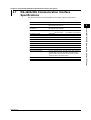
RS-422A/485 Communication Interface Specifications .............................................. 3-1
Terminal Arrangement and Signal Names and the Connection Procedure of the RS422A/485 Communication Interface ............................................................................. 3-2
Terminal Arrangement and Signal Names ....................................................................... 3-2
Connection Procedure ..................................................................................................... 3-2
Connection Example with a Host Computer .................................................................... 3-3
The Bit Structure of One Character and the Operation of the Receive Buffer ......... 3-7
The Bit Structure of One Character ................................................................................. 3-7
Receive Buffer and Received Data .................................................................................. 3-7
Modbus Slave Protocol Specifications ........................................................................ 3-8
Registers .......................................................................................................................... 3-9
Modbus Error Response .................................................................................................. 3-9
Setting the Serial Interface .......................................................................................... 3-10
v
App
Index
Contents
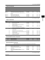
Chapter 4 Commands
4.1
4.2
4.3
4.4
4.5
4.6
4.7
4.8
4.9
4.10
Command Syntax ........................................................................................................... 4-1
Response ......................................................................................................................... 4-2
A List of Commands ...................................................................................................... 4-3
Execution Modes and User Levels .................................................................................. 4-3
Setting Commands .......................................................................................................... 4-3
Basic Setting Commands ................................................................................................. 4-4
Control Commands .......................................................................................................... 4-5
Output Commands ........................................................................................................... 4-5
RS-422A/485 Dedicated Commands ............................................................................... 4-5
Maintenance/Test Commands ......................................................................................... 4-5
Instrument Information Output Commands ...................................................................... 4-6
Parameter Values ........................................................................................................... 4-7
Input Range ..................................................................................................................... 4-7
Miscellaneous .................................................................................................................. 4-9
Setting Commands ...................................................................................................... 4-10
Basic Setting Commands ............................................................................................ 4-14
Control Commands ...................................................................................................... 4-20
Output Commands ....................................................................................................... 4-21
RS-422A/485 Dedicated Commands .......................................................................... 4-23
Maintenance/Test Commands (Available when using the maintenance/test server
function via Ethernet communications) .................................................................... 4-23
Instrument Information Output Commands (Available when using the instrument
information server function via Ethernet communications) .................................... 4-25
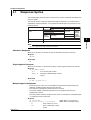
Chapter 5 Responses
5.1
5.2
5.3
Response Syntax ........................................................................................................... 5-1
Affirmative Response ....................................................................................................... 5-1
Single Negative Response ............................................................................................... 5-1
Multiple Negative Responses .......................................................................................... 5-1
ASCII Output .................................................................................................................... 5-2
BINARY Output ................................................................................................................ 5-2
RS-422A/485 Dedicated Commands and Responses ..................................................... 5-5
Output Format of ASCII Data ........................................................................................ 5-6
Setting/Basic Setting data ................................................................................................ 5-6
Decimal Point Position/Unit Information ........................................................................... 5-7
Measured Data ................................................................................................................ 5-8
Status Information .......................................................................................................... 5-10
User Information ............................................................................................................ 5-10
Output Format of BINARY Data .................................................................................. 5-11
Measured Data and FIFO Data ...................................................................................... 5-11
Chapter 6 Status Information
6.1
6.2
vi
Status Information and Filter ........................................................................................ 6-1
The Bit Structure of the Status Information ................................................................ 6-2
Status Information 1 ......................................................................................................... 6-2
Status Information 2 ......................................................................................................... 6-2
Status Information 3 ......................................................................................................... 6-2
Status Information 4 ......................................................................................................... 6-2
IM 04P03B01-17E
Contents
1
Appendix
Appendix 1 ASCII Character Codes .................................................................................... App-1
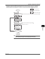
Appendix 2 Output Flow of FIFO Data ................................................................................ App-2
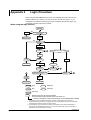
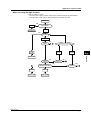
Appendix 3 Login Procedure .............................................................................................. App-4
Appendix 4 Communication Commands on the SR10000 and the SR1000 .................... App-6
2
Index
3
4
5
6
App
Index
IM 04P03B01-17E
vii
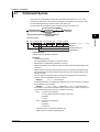
Chapter 1 Overview of the Communication Functions
1.1
The recorder can be equipped with an optional Ethernet interface. For details on how to
use the Ethernet interface, see chapter 2.
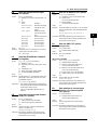
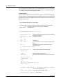
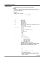
Functional Construction
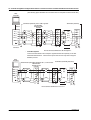
The following figure shows the relationship between the communication function of the
recorder and the Ethernet interface. Perform communication according to the respective
protocol.
* Protocol is a set of rules that two computers use to communicate via a communication line (or
network).
Application
Communication functions of the recorder
Setting/
Maintenance/
Measurement Server
Test Server
Login (user authentication/access
Instrument
privileges granting)
Information Server
Upper layer
protocol
Dedicated protocol
TCP
Lower layer
protocol
Interface
UDP
IP
Ethernet (10BASE-T)
Connect the recorder and the
PC using an Ethernet cable.
PC
TCP (Transmission Control Protocol)
UDP (User Datagram Protocol)
IP (Internet Protocol)
Setting/Measurement Server
• You can specify settings that are approximately equivalent to those specified by front
panel key operations. However, you cannot turn the power ON/OFF, set the user
name and password for communications, or set the customize menu or the key lock.
• The data below can be output.
Data Type
Output Format
Measured data
BINARY/ASCII
Setup data
ASCII
Most recent data of the periodic printout
ASCII
Status information
ASCII
Information on connected users
ASCII
• The commands that can be used are Setting commands, Basic Setting commands,
Control commands, and Output commands.
<Related Topics>
• Commands: Section 4.2
• Data output format: Chapter 5
IM 04P03B01-17E
1-1
1
Overview of the Communication Functions
Communication Functions Using the Ethernet
Interface (/C7 Option)
1.1 Communication Functions Using the Ethernet Interface (/C7 Option)
Maintenance/Test Server
• Outputs Ethernet communication information such as connection information and
network statistics from the recorder.
• The commands that can be used Maintenance/Test commands.
<Related Topics>
• Commands: Section 4.2
Instrument Information Server
• Outputs the serial number, model name, and other information about the recorder
connected via the Ethernet network.
• The commands that can be used Instrument Information Output commands.
<Related Topics>
• Commands: Section 4.2
Other Functions
• Login Function
Only users that are registered in advance can access the Setting/Measurement and
Maintenance/Test servers.
• Users are identified by their user name and password.
• You can register one administrator and six users.
Administrator privileges
The administrator can use all the functions on the Setting/Measurement and
Maintenance/Test servers
User Privileges
• Setting/Measurement server
Users can output measured data, setup data, and the most recent data of the
periodic printout. Users cannot control the recorder.
• Maintenance/Test server
Users cannot disconnect communications between the recorder and other PCs.
All other operations are allowed.
• There is a maximum number of simultaneous connections that can be established
with the recorder.
<Related Topics>
• Login function settings: Section 2.6
• Maximum number of simultaneous connections: Section 2.1
• Commands available to the administrator and users: Section 4.2
• Communication Timeout
This function drops the connection with the PC if there is no data transmission for a
given time at the application level (see “Functional Construction”). For example, this
function prevents a PC from being connected to the recorder indefinitely which would
prohibit other users from making new connections for data transfer.
<Related Topics>
• Communication timeout setting using communication comands: Section 4.2
• Keepalive
This function drops the connection if there is no response to the inspection packet that
is periodically transmitted at the TCP level.
<Related Topics>
• Keepalive setting using communication comands: Section 4.2
1-2
IM 04P03B01-17E
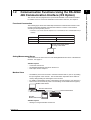
1.2
The recorder can be equipped with an optional RS-422A/485 communication interface.
For details on how to use the RS-422A/485 communication interface, see chapter 3.
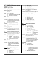
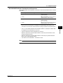
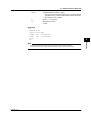
Functional Construction
The following figure shows the relationship between the communication function of the
recorder and the RS-422A/485 communication interface. Perform communication
according to the respective protocol.
* Protocol is a set of rules that two computers use to communicate via a communication line (or
network).
Communication functions of the recorder
Application
Setting/Measurement Server
Modbus Slave
Protocol
Dedicated protocol
Modbus protocol
Interface
RS-422A/485
Connect the recorder and the
PC using a serial cable.
PC
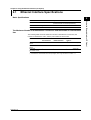
Setting/Measurement Server
The functions are the same as those of the Setting/Measurement server of the Ethernet
interface. See page 1-1.
<Related Topics>
• Commands: Section 4.2
• RS-422A/485 dedicated commands: Section 4.8
• Data output format: Chapter 5
Modbus Slave
• The Modbus protocol can be used to read the measured data on your PC by reading
the input registers of the recorder. The communication input data can be written or
read by writing/reading the hold register of the recorder.
• For details on the Modbus function codes that the recorder supports, see section 3.4.
• This function can be used only when communicating via the serial interface (option).
Modbus master device
Data from slave device
Data to slave device
Serial communication
Recorder
Modbus slave device
<Related Topics>
• Settings for using the Modbus: Section 3.5
IM 04P03B01-17E
1-3
1
Overview of the Communication Functions
Communication Functions Using the RS-422A/
485 Communication Interface (/C3 Option)
Chapter 2 Using the Ethernet Interface (/C7 Option)
2.1
Ethernet Interface Specifications
Basic Specifications
2
Specifications
Electrical and mechanical specifications
Conforms to IEEE 802.3
(Ethernet frames are of DIX specification)
Transmission medium type
10BASE-T
Protocol
TCP, IP, UDP, ICMP, and ARP
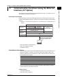
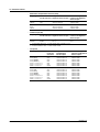
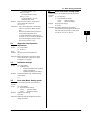
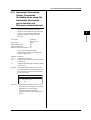
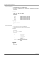
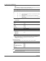
The Maximum Number of Simultaneous Connections and the Number of Simultaneous
Use
The following table shows the maximum number of simultaneous connections, the
number of simultaneous users, and the port numbers of the recorder.
Function
Port Number†
Setting/Measurement 3
server
1
2††
34260/tcp
Maintenance/Test
server
1
1
1††
34261/tcp
Instrument
Information server
-
-
-
34264/udp
†
††
IM 04P03B01-17E
Maximum Number Number of Simultaneous Users
of Connections
<Administrators>
<Users>
The port numbers are fixed.
For details on administrator and user privileges, see “Login Function” in section 1.1.
2-1
Using the Ethernet Interface (/C7 Option)
Item
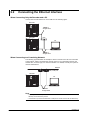
2.2
Connecting the Ethernet Interface
When Connecting Only the Recorder and a PC
Connect the recorder and the PC via a HUB as in the following figure.
Recorder
10BASE-T
straight cable
Recorder
Hub
PC
10BASE-T
straight cable
When Connecting to a Preexisting Network
The following figure illustrates an example in which a recorder and a PC are connected
to the network. When connecting the recorder or the PC to a preexisting network, the
transfer rate, connector type, etc. must be matched. For details, consult your system or
network administrator.
Network
Hub, router, etc.
Recorder
PC
10BASE-T
straight cable
Note
• Depending on the reliability of the network or the volume of network traffic, all the transferred
data may not be retrieved by the PC.
• Communication performance deteriorates if multiple PCs access the recorder simultaneously.
2-2
IM 04P03B01-17E
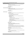
2.3
Configuring the Ethernet Interface
2
Setup Items and Setup Procedure
Setup Procedure
Keys
Communication
(reference section) commands (section 4.2)
Yes
–
Yes
Yes (section 2.4)
Yes
–
Yes
Yes (section 2.5)
–
Yes (section 2.5)
Yes
–
Yes
–
Setup Items
Host name and domain name
IP address
DNS
Login function enable/disable
User registration
Communication timeout
Keepalive
For items that can only be set using communication commands, assign an IP address to
the recorder, connect to the PC, and then set the items.
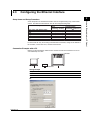
Connection Example with a PC
Below is a setup example in which the PC and the recorder are connected in a one-toone relationship via a hub.
Recorder
PC
HUB
Ethernet
Setting Example
Setup Item
Recorder
PC
IP address
192.168.1.101
192.168.1.100
Subnet mask
255.255.255.0
255.255.255.0
PC
IM 04P03B01-17E
2-3
Using the Ethernet Interface (/C7 Option)
Some setup items of the Ethernet interface can be configured using keys, while others
cannot. The items that are listed as Yes can be configured using keys.
2.4
Setting the IP Address
The IP address must be assigned to the recorder.
Setup Items
BS COMM
IP
A1
255 A2
255
IP address
END
A3
255
A4
255
IP address
M1
255
M2
255
M3
255
M4
255
G2
255
G3
255
G4
255
Subnet mask
G1
255
Default gateway
Procedure
1.
2.
3.
Hold down the MENU key for 3 seconds to display the Setting mode screen.
Hold down the
and
keys simultaneously for 3 seconds to display the
Basic Setting mode screen.
Carry out the procedure shown in the figure below.
Use the
,
, or
key to select values.
If you press the
key, the operation is cancelled, and the display returns to a
higher level menu.
(COMM)
Select IP.
(IP address)
IP address
Set the IP address.
Subnet mask
Sets the subnet mask.
(To the next page)
2-4
IM 04P03B01-17E
2.4 Setting the IP Address
(From the previous page)
2
Default gateway
Using the Ethernet Interface (/C7 Option)
Set the default gateway.
The settings are activated.
(OK)
4.
5.
If you are done, press the
key.
To return to the Operation mode,
1. Press the
key, use the
or
key.
2. Press the
or
key to select
key.
key to select
or
, and press the
, and press the
Explanation
For details on the settings, consult your system or network administrator.
• IP address (
to
)
• Set the IP address to assign to the recorder. The default value is 0.0.0.0.
• The IP address is used to distinguish between the various devices connected to
the Internet when communicating using the TCP/IP protocol. The address is a 32bit value expressed using four octets (each 0 to 255), each separated by a period
as in [192.168.111.24].
• Subnet mask (
to
)
• Specify the mask that is used to determine the network address of the subnet from
the IP address. The default value is 0.0.0.0.
• Set this value according to the system or the network to which the recorder
belongs. In some cases, this setting may not be necessary.
• Default Gateway (
to
)
• Set the IP address of the gateway (router, etc.) used to communicate with other
networks. The default value is 0.0.0.0.
• Set this value according to the system or the network to which the recorder
belongs. In some cases, this setting may not be necessary.
• Saving the Settings
To activate the settings made in the Basic Setting mode, the settings must be saved.
IM 04P03B01-17E
2-5
2.5
Checking the Connection Status
The connection status of the Ethernet interface can be confirmed with the indicator that
is located to the left of the Ethernet port on the recorder.
Indicator
Connection Status of the Ethernet Interface
ON (Green)
The Ethernet interface is electrically connected.
Blinking (Green)
Transmitting data.
OFF
The Ethernet interface is not electrically connected.
Optional terminal block
Indicator
Ethernet port
2-6
IM 04P03B01-17E
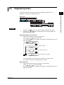
2.6
Registering Users
Users that are allowed to access the recorder via the Ethernet network must be
registered. This function is called login function.
LOGIN
Login
END
Using the Ethernet Interface (/C7 Option)
Setup Items
BS COMM
2
NOT
USE/NOT
LOGST
ADMIN
Level
User
registration
RE ON
Registration ON/OFF
NAME
01 44-20
08 44-20
User name (16 characters)
PASSW
01 41-20
04 41-20
Password (4 characters)
Procedure
1.
2.
Hold down the MENU key for 3 seconds to display the Setting mode screen.
Hold down the
and
keys simultaneously for 3 seconds to display the
Basic Setting mode screen.
Enabling/Disabling the Login Function
3.
Carry out the procedure shown in the figure below.
Use the
,
, or
key to select values.
If you press the
key, the operation is cancelled, and the display returns to a
higher level menu.
(COMM)
Select LOGIN.
(LOGIN)
Select USE or NOT.
(USE/NOT)
The settings are activated.
(OK)
If you selected NOT, you are done with the settings. Proceed to step 6.
If you select USE, proceed to “Registering Users” below.
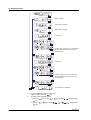
Registering Users
4.
Carry out the procedure shown in the figure on the next page.
Use the
,
, or
key to select values.
If you press the
key, the operation is cancelled, and the display returns to a
higher level menu.
IM 04P03B01-17E
2-7
2.6 Registering Users
(COMM)
Select LOGST.
Select the user level.
(ADMIN)
Select ON to register.
(ON/OFF)
User name.
(NAME)
1st char
1st character code
2nd char
2nd character code
:
:
Set the user name (up to 16 characters).
For the characters that can be used,
see appendix 1.
16th character code
Password.
(PASSW)
1st char
1st character code
2nd char
2nd character code
:
:
Set the password (up to 4 characters).
For the characters that can be used,
see appendix 1.
4th character code
The settings are activated.
(OK)
5
6.
2-8
Press the
key to register other users.
If you are done, press the
key.
To return to the Operation mode,
1. Press the
key, use the
or
key to select
key.
2. Press the
or
key to select
or
key.
, and press the
, and press the
IM 04P03B01-17E
2.6 Registering Users
Explanation
You can limit the users that can access the Setting/Measurement and Maintenance/Test
servers on the recorder via the Ethernet interface.
2
Disable (
)
• Registering Users
• User Level
Select administrator (
) or user (
to
).
• Administrator
One administrator can be registered. An administrator has the authority to use all
Setting/Measurement server and Maintenance/Test server commands of the
recorder.
• User
Six users can be registered. A user has limited authority to use the commands.
See section 4.2.
• Selecting Whether to Register (
/
) the User
When registering a user, set the user name and password.
• User name (
)
• Set the user name using up to 16 alphanumeric characters. Use ASCII
character codes for the characters. For the characters that can be used, see
appendix 1.
• The same user name cannot be registered.
• Since the word “quit” is reserved as a command on the recorder, the user name
“quit” is not allowed.
• Password (
)
Enter the password using up to 4 characters. Alphanumeric characters and space
can be used. Specify using ASCII character codes..
Note
• The relationship between the login function and the user name that is used when accessing
the recorder is as follows:
• When the login function is set to “USE”
• The registered user name and password can be used to login to the recorder.
• The user level is the level that was specified when the user name was registered.
• When the login function is set to “NOT”
• The user name “admin” can be used to login to the recorder as an administrator.
Password is not necessary.
• The user name “user” can be used to access the recorder as a user. Password is not
necessary.
• There are limitations on the number of simultaneous connections or simultaneous uses of the
recorder from the PC (see section 2.1).
• For a description of the login process of the Setting/Measurement server and Maintenance/
Test server, see appendix 3.
• Saving the Settings
To activate the settings made in the Basic Setting mode, the settings must be saved.
IM 04P03B01-17E
2-9
Using the Ethernet Interface (/C7 Option)
• Enabling/Disabling the Login Function
Enable (
)
Chapter 3 Using the RS-422A/485 Communication Interface (/C3 Option)
3.1
RS-422A/485 Communication Interface
Specifications
This section describes the RS-422A/485 communication interface specifications.
Specifications
Terminal block type
Number of terminals: 6, terminal attachment screws: ISO
M4/nominal length of 6 mm
Electrical and mechanical
specifications
Complies with the EIA-422A(RS-422A) and
EIA-485(RS-485) standards
Connection
Multidrop Four-wire system
Two-wire system
Transmission mode
Half-duplex
3
1:32
1:31 (Modbus slave protocol)
Synchronization
Start-stop synchronization
Baud rate
Select from 1200, 2400, 4800, 9600, 19200, and 38400 [bps].
Start bit
Fixed to 1 bit
Data length
Select 7 or 8 bits
Parity
Select Odd, Even, or None (no parity).
Stop bit
Fixed to 1 bit
Received buffer length
2047 bytes
Escape sequence
Open and close
Electrical characteristics
6 points consisting of FG, SG, SDB, SDA, RDB, and RDA
The SG, SDB, SDA, RDB, and RDA terminals and the
internal circuitry of the recorder are functionally isolated.
The FG terminal is the frame ground.
Communication distance
Up to 1.2 km
Terminal resistance
120 Ω, 1/2 W
3-1
Using the RS-422A/485 Communication Interface (/C3 Option)
IM 04P03B01-17E
Item
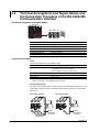
3.2
Terminal Arrangement and Signal Names and
the Connection Procedure of the RS-422A/485
Communication Interface
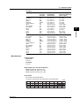
Terminal Arrangement and Signal Names
Rear panel
L
ALARM
N
NO
C
NC
NO
C
NC
NO
C
NC
NO
C
NC
CHART
NO
C
NC
NO
C
NC
SDA SDB
SG
RS-422A
REMOTE
1
2
3
4
5 C
SD SD SG
A B
RS-422A
SD SD SG
A B G
RD RD FG
A B
RD RD FG
A B G
RDA RDB
Terminal Name
FG
Description
FG (Frame Ground)
Case ground of the recorder.
SG (Signal Ground)
Signal ground.
SDB (Send Data B)
Send data B (+).
SDA (Send Data A)
Send data A (–).
RDB (Received Data B)
Receive data B (+).
RDA (Received Data A)
Receive data A (–).
Connection Procedure
• Cable
Use the cable that meets the conditions below.
Item
Conditions
Cable
Shielded twisted pair cable
3 pairs AWG24-14 (Four-wire system),
2 pairs 24 AWG or more (Two-wire system)
Characteristic impedance
100 Ω
Capacitance
50 pF/m
Cable length
Up to 1.2 km*
*
The transmission distance of the RS-422A/485 interface is not the straight-line distance, but
rather the total length of the (shielded twisted-pair) cable.
• Connecting the Cable
As shown in the following figure, attach a crimp-on lug with isolation sleeves for 4 mm
screws to the end of the cable. Keep the exposed section from the end of the shield
within 5 cm.
Four-wire system
Two-wire system
Shield
Shield
SDA SDB SG
SDA SDB SG
RDA RDB FG
RDA RDB FG
Electric
potential of
the shield
3-2
Electric
potential of
the shield
IM 04P03B01-17E
3.2 Terminal Arrangement and Signal Names and the Connection Procedure of the RS-422A/485 Communication Interface
WARNING
To prevent the possibility of electric shock, connect the cables with the power
turned OFF.
Note
•
Connection Example with a Host Computer
A connection can be made with a host computer having a RS-232, RS-422A, or RS-485
port.
• In the case of RS-232, a converter is used.
• For recommended converters, see “Serial Interface Converter” on the next page.
• The two-wire system can be used only when using the Modbus protocol. For the
configuration procedure, see section 3.5
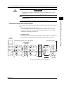
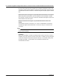
• Four-Wire System
Generally, a four-wire system is used to connect to a host computer. In the case of a
four-wire system, the transmission and reception lines need to be crossed over.
Host
computer
Terminator (external)
Terminator (external) 120 Ω 1/2W or greater
RS-422A/485
terminal on the
recorder
SD A
SDA( - )
(SDA)
SDB( + )
(SDB)
RDA( - )
SD A
(SDA)
SD B
SD B
(SDB)
RD A
(RD A)
(RD B)
SG
(SG)
(RD A)
SG
(RD A)
RD B
(RD B)
SG
(SG)
#1
RD A
RD B
(RD B)
FG
SD B
(SDB)
RD A
RD B
RDB( + )
SD A
(SDA)
SG
(SG)
FG
#2
FG
#n
(#n ≤ 32)
Do not connect terminators to #1 through #n-1.
IM 04P03B01-17E
3-3
3
Using the RS-422A/485 Communication Interface (/C3 Option)
•
Connect the RD pin to the SD (TD) pin on the PC (converter) end and the SD pin to the RD
pin on the PC end.
The two-wire system can be used only when using the Modbus protocol.
3.2 Terminal Arrangement and Signal Names and the Connection Procedure of the RS-422A/485 Communication Interface
(The following figure illustrates the case when the host computer’s interface is RS-232.)
Host
computer
Terminator (external)
Terminator (external) 120 Ω 1/2W or greater
RS-422A/485
terminal on the
recorder
RS-232
SD A
TD( - )
(SDA)
TD( + )
(SDB)
RD( - )
(SDA)
SD B
SD B
(SDB)
RD A
(RD A)
SHIELD
(SG)
RD A
(RD A)
(RD A)
RD B
(RD B)
SD B
(SDB)
RD A
RD( + )
SD A
SD A
(SDA)
RD B
RD B
(RD B)
(RD B)
SG
SG
SG
(SG)
(SG)
FG
FG
#2
#1
Converter
FG
#n
(#n ≤ 32)
Do not connect terminators to #1 through #n-1.
• Two-Wire System
Connect the transmission and reception signals with the same polarity on the RS422A/485 terminal block. The two-wire system can be used only when using the
Modbus protocol.
Host
computer
Terminator (externally attached) 120 Ω, 1/2 W or more
Terminator (externally attached)
RS-422A/485
terminal on the
recorder
SDA( – )
(A)
SDB( + )
(B)
RDA( – )
RDB( + )
SG
(SG)
SD A
SD B
(A)
(B)
SD A
SD B
(A)
(B)
SD A
SD B
RD A
RD A
RD A
RD B
RD B
RD B
SG
FG
#1
(SG)
SG
(SG)
FG
#2
SG
FG
#n
(#n ≤ 31)
Do not connect terminator to #1 to #n–1
3-4
IM 04P03B01-17E
3.2 Terminal Arrangement and Signal Names and the Connection Procedure of the RS-422A/485 Communication Interface
(The following figure illustrates the case when the host computer’s interface is RS-232.)
Host
computer
Terminator (externally attached) 120 Ω, 1/2 W or more
RS-232
(A)
RD( + )
(B)
TD( – )
TD( + )
(SG)
SD A
SD B
(A)
(B)
SD A
SD B
(A)
(B)
SD A
SD B
RD A
RD A
RD A
RD B
RD B
RD B
SG
SG
FG
#1
Converter
3
(SG)
(SG)
FG
#2
SG
FG
#n
(#n ≤ 31)
Do not connect terminator to #1 to #n–1
Note
•
•
The method used to eliminate noise varies depending on the situation. In the connection
example, the shield of the cable is connected only to the recorder’s ground (one-sided
grounding). This is effective when there is a difference in the electric potential between the
computer’s ground and the recorder’s ground. This may be the case for long distance
communications. If there is no difference in the electric potential between the computer’s
ground and the recorder’s ground, the method of connecting the shield also to the computer’s
ground may be effective (two-sided grounding). In addition, in some cases, using two-sided
grounding with a capacitor connected in series on one side is effective. Consider these
possibilities to eliminate noise.
When using the two-wire type interface (Modbus protocol), the 485 driver must be set to high
impedance within 3.5 characters after the last data byte is sent by the host computer.
• Serial Interface Converter
Recommended converter
MODEL RC-57 by RA SYSTEMS CORP.
CAUTION
Some converters not recommended by Yokogawa have FG and SG pins that
are not isolated. In this case, do not connect anything to the converter’s FG and
SG pins (unlike the figure on the previous page). Especially in the case of long
distance communications, the potential difference that appears may damage the
recorder or cause communication errors. For converters that do not have the
SG pin, they can be used without using the signal ground. For details, see the
manual that came with the converter.
On some non-recommended converters, the signal polarity may be reversed (A/B or
+/- indication). In this case, reverse the connection.
IM 04P03B01-17E
3-5
Using the RS-422A/485 Communication Interface (/C3 Option)
RD( – )
SHIELD
Terminator (externally attached)
RS-422A/485
terminal on the
Recorder
3.2 Terminal Arrangement and Signal Names and the Connection Procedure of the RS-422A/485 Communication Interface
For a two-wire system, the host computer must control the transmission driver of the
converter in order to prevent collisions of transmit and received data. When using the
recommended converter, the driver is controlled using the RS (RTS) signal on the RS232.
• When Instruments That Support Only the RS-422A Interface Exist in the System
When using the four-wire system, up to 32 recorders can be connected to a single
host computer. However, this may not be true if instruments that support only the RS422A interface exist in the system.
When the instrument that support only the RS-422A interface exist in the
system
The maximum number of connection is 16. Some of YOKOGAWA’s conventional
recorder only support the RS-422A driver. In this case, only up to 16 units can be
connected.
Note
In the RS-422A standard, 10 is the maximum number of connections that are allowed on one
port (for a four-wire system).
• Terminator
When using a multidrop connection (including a point-to-point connection), connect a
terminator only to the recorder on the end of the chain. In addition, turn the terminator
on the host computer ON (see the computer’s manual). If a converter is being used,
turn ON its terminator. The terminator must be attached externally to the
recommended converters.
3-6
IM 04P03B01-17E
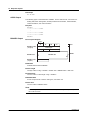
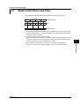
3.3
The Bit Structure of One Character and the
Operation of the Receive Buffer
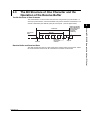
The Bit Structure of One Character
The serial interface on the recorder communicates using start-stop synchronization. In
start-stop synchronization, a start bit is added every time a character is transmitted. The
start bit is followed by the data bits, parity bit, and stop bit. (See the figure below.)
Data bit
(7 or 8 bits)
Circuit idle
state
Start bit
Parity bit
Even, Odd,
or None
Stop bit
Receive Buffer and Received Data
The data received from the PC is first placed in the receive buffer of the recorder. When
the received buffer becomes full, all of the data that overflow are discarded.
IM 04P03B01-17E
3-7
3
Using the RS-422A/485 Communication Interface (/C3 Option)
1 character
Return to the idle
state (dotted line)
or the start bit of
the next data
character
(solid line)
3.4
Modbus Slave Protocol Specifications
The Modbus slave protocol specifications of the recorder are as follows:
Item
Specifications
Transmission medium
RS-422A/485
Flow control
None only
Baud rate
Select from 1200, 2400, 4800, 9600, 19200, or 38400 [bps]
Start bit
Fixed to 1 bit
Stop bit
Fixed to 1 bit
Parity check
Select odd, even, or none (no parity).
Transmission mode
RTU (Remote Terminal Unit) mode only
• Data length: 8 bits
• Data interval: 24 bits or less*
• Error detection: Uses CRC-16
* Determines message termination with a time interval to 3.5
characters or more.
Maximum number of
connected units
Four-wire system: 32 slave devices
Two-wire system: 31 slave devices
The function codes of the Modbus slave protocol that the recorder supports are shown
below. The recorder does not support broadcast commands.
Function Code
Specifications
Operation
4
Read the input register (3xxxx).
The master device loads the
measured, alarm, and time
data of the recordr.
8
Loopback test
The master device performs a
loopback test of the recorder.
The recorder only supports
message return (test code
0x00*)
*
3-8
Hexadecimal “00”
IM 04P03B01-17E
3.4 Modbus Slave Specifications
Registers
The registers for using the Modbus slave protocol are listed below.
The register data does not contain unit and decimal point position information. Set them
on the Modbus master. Binary values are stored to the register in order from the highest
byte.
Input register
Data
31001
Alarm status of the measured data of CH01
:
:
31006
Alarm status of the measured data of CH06
• The data is a 16-bit signed integer. The value is the same as the alarm status in binary
output format (see page 5-12). The data is entered in the "A2A1A4A3" order in the register.
• Valid channels vary depending on the device. An error response (code 2) occurs when an
invalid channel is read.
36001
List of alarms of the measured data of CH01 to CH04
36002
List of alarms of the measured data of CH05 to CH08
Example of Register 36001
1 register (1 word)
CH4
CH3
CH2
The bit is set to 1 when an alarm occurs.
36003 to 36020
Always 0
39001
39002
39003
39004
39005
39006
39007
39008
Year (4 digits)
Month
Day
Hour
Minute
Second
Millisecond
Summer/Winter time
CH1
Level 1
Level 2
Level 3
Level 4
Modbus Error Response
The recorder returns the following error codes to the master device. For the error
messages related to communications that the recorder displays, see appendix 4.
Code
Meaning
Cause
1
Bad function code
Unsupported function request.
2
Bad register number
Attempted to read/write to a register that
has no corresponding channel.
3
Bad number of registers
The specified number of registers is less
than or equal to 0 or greater than or
equal to 126 (when reading)/124 (when
writing).
However, no response is returned for the following cases.
• CRC error
• Errors other than those in the table above.
IM 04P03B01-17E
3-9
3
Using the RS-422A/485 Communication Interface (/C3 Option)
30001
Measured data of CH01
:
:
30006
Measured data of CH06
• The data is a 16-bit signed integer. The value is the same as the measured data in binary
output format (see page 5-13).
• The decimal point and unit information varies depending on the range setting of each
channel.
• Valid channels vary depending on the device. An error response (code 2) occurs when an
invalid channel is read.
3.5
Setting the Serial Interface
The serial interface must be configured.
Setup Items
BS COMM
38400
01
Address
Baud rate
8BIT
Data length
EVEN
Parity
PT NORMA
Protocol
END
Procedure
1.
2.
3.
Hold down the MENU key for 3 seconds to display the Setting mode screen.
Hold down the
and
keys simultaneously for 3 seconds to display the
Basic Setting mode screen.
Carry out the procedure shown in the figure below.
Use the
,
, or
key to select values.
If you press the
key, the operation is cancelled, and the display returns to a
higher level menu.
(COMM)
Select the address value.
Select the baud rate.
Select the data length.
Select the parity.
Select the protocol.
Protocol
The settings are activated.
(OK)
4.
5.
3-10
If you are done, press the
key.
To return to the Operation mode,
1. Press the
key, use the
or
key.
2. Press the
or
key to select
key.
key to select
or
, and press the
, and press the
IM 04P03B01-17E
3.5 Setting the Serial Interface
Explanation
• Address
Select the address from the following range.
01 to 32
• Baud rate
Select the baud rate from the following:
1200, 2400, 4800, 9600, 19200, or 38400
3
• Parity (Parity check method)
Select the parity check from the following:
Odd (
), Even (
), or None (
)
• Protocol
Select the protocol when using the Modbus slave protocol.
NORMAL (
): Standard protocol
MODBUS (
): Modbus slave protocol
• Saving the Settings
To activate the settings made in the Basic Setting mode, the settings must be saved.
IM 04P03B01-17E
3-11
Using the RS-422A/485 Communication Interface (/C3 Option)
• Data length
Select the data length from below. To output data in BINARY format, be sure to set
the data length to 8 bits.
7 or 8
Chapter 4 Commands
4.1
Command Syntax
The syntax of the setting/basic setting/output commands (see sections 4.4 to 4.7) of the
instrument is given below. ASCII codes (see appendix 1) are used for the character codes.
For the Maintenance/Test command syntax, see section 4.9.
For the Instrument Information server command syntax, see section 4.10.
?
Command name
Parameter
Terminator
Delimiter
Sub delimiter
4
SR 02,SKIP;SR 03,VOLT,2V,-1500,1800
Parameter (02 SKIP·····1800)
Delimiter (,)
Command name (SR)
Sub delimiter (;)
• Command Name
Defined using two alphabet characters.
• Parameter
• Command parameters.
• Set using alphabet characters or numerical values.
• Parameters are separated by delimiters (commas).
• When the parameter is a numerical value, the valid range varies depending on the
command.
• Spaces before and after of the parameter are ignored (except for parameters that
are specified using an ASCII character string (unit, tag, and message string), when
spaces are valid.)
• You can omit the parameters that do not need to be changed from their current
settings. However, delimiters cannot be omitted.
Example
SR 01,,2V<terminator>
If multiple parameters are omitted and delimiters occur at the end of the command,
those delimiters can be omitted.
Example
SR 01,VOLT,,,<terminator> → SR 01,VOLT<terminator>
• The number of digits of the parameters below is fixed. If the number of digits is not
correct when entering the command, a syntax error results.
• Date
YY/MM/DD (8 characters)
YY: Year (Enter the lower two digits of the year.)
MM: Month
DD: Day
• Time HH:MM:SS (8 characters)
HH: Hour
MM: Minute
SS: Second
• Channel number: 2 characters (Example: 01)
• Relay number: 3 characters (Example: I01)
IM 04P03B01-17E
4-1
Commands
Command example
4.1 Command Syntax
• Query
• A question mark is used to specify a query.
• By placing a query after a command or parameter, the setting information of the
corresponding command can be queried. Some commands cannot execute
queries. For the query syntax of each command, see sections 4.4 to 4.7.
Example 1
SR[ p1]?
SR? or SR p1? can be executed.
Example 2
SA[ p1[,p2]]? SA?, SA p1?, or SA p1,p2? can be executed.
• Delimiter
• A comma is used as a delimiter.
• Parameters are separated by delimiters.
• Sub Delimiter
• A semicolon is used as a sub delimiter.
• By separating each command with a sub delimiter, up to 10 commands can be
specified one after another. However, the following commands and queries cannot
be specified one after another. Use them independently.
• Output commands other than BO, CS, and IF commands.
• YE command
• Queries
* If there are consecutive sub delimiters, they are considered to be single. In addition, sub
delimiters at the front and at the end are ignored.
Example
;SR01,VOLT;;;SR02,VOLT;<terminator> is taken to be
SR01,VOLT;SR02,VOLT<terminator>.
• Terminator (Terminating Character)
Use either of the following two characters for the terminator.
• CR + LF (0DH 0AH in ASCII code.)
• LF (0AH in ASCII code.)
Note
• The total data length from the first character to the terminator must be less than 2047 bytes. In
addition, the character string length of 1 command must be less than 512 bytes.
• Commands are not case sensitive (with the exception of user-specified character strings).
• All the commands that are listed using sub delimiters are executed even if one of the
commands is erroneous.
• Spaces that are inserted before and after a parameter are ignored. However, if spaces are
inserted before a command, after a sub delimiter, or after a query, an error occurs.
Response
The recorder returns a response (affirmative/negative response) to a command that is
separated by a single terminator.* The controller should follow the one command to one
response format. When the command-response rule is not followed, the operation is not
guaranteed.
For the response syntax, see section 5.1.
* The exceptions are the RS-422A/485 dedicated commands (see section 4.8).
Note
When using the RS-422A/485 interface, allow at least 1 ms before sending the next command
after receiving a response. Otherwise, the command may not be processed correctly.
4-2
IM 04P03B01-17E
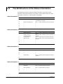
4.2
A List of Commands
Execution Modes and User Levels
Setting Commands
Name
SR
VB
VL
SA
SN
SC
SD
VT
SZ
SP
VR
ST
SG
SE
SV
SF
TD
FR
Function
Sets the input range.
Sets the bias.
Sets the calibration correction (/CC1 option).
Sets the alarm.
Sets the unit.
Sets the chart speed.
Sets the date and time.
Sets the dot printing interval (dot model).
Sets zone recording.
Sets the partial expanded recording.
Turns ON/OFF the recording on each channel.
Sets the tag.
Sets the message.
Sets the secondary chart speed
(used by the remote control function (/R1 option)).
Sets the moving average (dot model).
Sets the input filter (pen model).
Sets the DST.
Sets the acquiring interval to the FIFO buffer.
Execution Mode
Run mode
Run mode
Run mode
Run mode
Run mode
Run mode
Run mode
Run mode
Run mode
Run mode
Run mode
Run mode
Run mode
Run mode
Administrator
Yes
Yes
Yes
Yes
Yes
Yes
Yes
Yes
Yes
Yes
Yes
Yes
Yes
Yes
User
No
No
No
No
No
No
No
No
No
No
No
No
No
No
Page
4-10
4-11
4-11
4-11
4-12
4-12
4-12
4-12
4-12
4-13
4-13
4-13
4-13
4-13
Run mode
Run mode
Run mode
Run mode
Yes
Yes
Yes
Yes
No
No
No
No
4-13
4-13
4-14
4-14
Yes: Command usable
No: Command not usable
IM 04P03B01-17E
4-3
4
Commands
Execution Modes
The recorder has two execution modes. Each command is specified to be used in a
particular execution mode. If you attempt to execute a command in a mode that is
different from the specification, a syntax error occurs. Use the DS command to switch to
the appropriate mode, and then execute the command. Query commands can be
executed in either mode.
• Basic Setting mode
Measurement is stopped and settings are changed in this mode.
• Run mode
Run mode collectively refers to Operation mode and Setting mode of the recorder.
User Levels
The administrator and user specifications in the table indicate the user level that is
specified using the login function for Ethernet communications. For details, see section
1.1.
4.2 A List of Commands
Basic Setting Commands
Note
• In order to activate the settings that are changed using the basic setting commands, the
settings must be saved using the YE or XE command.
• The settings that are returned in response to a query in the basic setting mode will contain the
new settings even if they are not saved.
• When the settings are saved with the XE command, communication is not dropped. The
settings that are changed using the YS/YB/YA/YN/YD/YQ/YK command are activated after
power-cycling the recorder.
• When the YE command is executed, communication is dropped. The response to the YE
command is not returned.
Name
XA
XI
XB
XJ
UC
UO
UP
UR
UI
UJ
UK
UL
XN
XT
UF
UT
XR
YS
YB
YA
YN
YD
YQ
YK
UQ
UG
UH
UA
UY
YC
YE
XE
Function
Sets alarm related settings.
Sets the A/D integral time.
Sets the burnout detection.
Sets the RJC.
Changes the dot color (dot model).
Sets the pen offset compensation (pen model).
Sets the items to be printed.
Sets the periodic printout interval.
Sets whether to use moving average (dot model).
Sets whether to use the input filter (pen model).
Sets whether to use of partial expanded recording.
Selects the printout font.
Selects the date format.
Selects the temperature unit.
Sets whether to use the extended functions.
Selects the time printout format.
Sets the remote control input (/R1 option).
Sets the RS-422A/485 interface (/C3 option).
Sets the host name and domain name (/C7 option).
Sets the IP address (/C7 option).
Sets the DNS (/C7 option).
Sets whether to use the login function via communication
(/C7 option).
Sets the communication timeout (/C7 option)
Sets keepalive (/C7 option).
Sets the calibration correction setting mode and the
number of correction points (/CC1 option).
Shows/Hides setting mode menu items.
Show/Hides FUNC key menu items.
Sets the record position.
Stops the record position adjustment.
Initializes the settings.
Exits from Basic Setting mode.
Exits from Basic Setting mode.
Execution Mode
Basic Setting mode
Basic Setting mode
Basic Setting mode
Basic Setting mode
Basic Setting mode
Basic Setting mode
Basic Setting mode
Basic Setting mode
Basic Setting mode
Basic Setting mode
Basic Setting mode
Basic Setting mode
Basic Setting mode
Basic Setting mode
Basic Setting mode
Basic Setting mode
Basic Setting mode
Basic Setting mode
Basic Setting mode
Basic Setting mode
Basic Setting mode
Basic Setting mode
Administrator
Yes
Yes
Yes
Yes
Yes
Yes
Yes
Yes
Yes
Yes
Yes
Yes
Yes
Yes
Yes
Yes
Yes
Yes
Yes
Yes
Yes
Yes
User
No
No
No
No
No
No
No
No
No
No
No
No
No
No
No
No
No
No
No
No
No
No
Page
4-14
4-14
4-14
4-15
4-15
4-15
4-15
4-15
4-16
4-16
4-16
4-16
4-16
4-16
4-16
4-16
4-17
4-17
4-17
4-17
4-17
4-17
Basic Setting mode
Basic Setting mode
Basic Setting mode
Yes
Yes
Yes
No
No
No
4-18
4-18
4-18
Basic Setting mode
Basic Setting mode
Basic Setting mode
Basic Setting mode
Basic Setting mode
Basic Setting mode
Basic Setting mode
Yes
Yes
Yes
Yes
Yes
Yes
Yes
No
No
No
No
No
No
No
4-18
4-18
4-18
4-19
4-19
4-19
4-19
Yes: Command usable
No: Command not usable
4-4
IM 04P03B01-17E
4.2 A List of Commands
Control Commands
Key
-
Name
DS
Function
Switches the execution mode.
Execution Mode
All modes
Administrator User Page
Yes
No
4-20
RCD
PS
Starts/Stops recording.
Run mode
Yes
No
4-20
DISP
UD
Switches the screen/switches the channel.
Run mode
Yes
No
4-20
Starts/Stops manual print.
Starts/Stops the list (setting information) printout.
Starts/Stops the setup list (basic setting information)
printout.
Executes the message printout.
Clears the alarm printout buffer.
Clears the message printout buffer.
Run mode
Run mode
Run mode
Yes
Yes
Yes
No
No
No
4-20
4-20
4-20
Run mode
Run mode
Run mode
Yes
Yes
Yes
No
No
No
4-20
4-20
4-20
FUNC MP
FUNC LS
FUNC SU
FUNC MS
FUNC AC
FUNC MC
Output Commands
Type
Control
Name
Function
Execution Mode
Administrator User Page
BO
CS
Sets the byte output order.
Sets the check sum
(usable only during serial communications).
Sets the status filter
Disconnects an Ethernet connection
(usable only during Ethernet communications)
All modes
All modes
Yes
Yes
Yes
Yes
4-21
4-21
All modes
All modes
Yes
Yes
Yes
Yes
4-21
4-21
All modes
Yes
Yes
4-21
Run mode
Run mode
Run mode
All modes
All modes
Yes
Yes
Yes
Yes
Yes
Yes
Yes
Yes
Yes
Yes
4-21
4-21
4-21
4-22
4-22
IF
CC
Setup and measurement data output
FE
Outputs decimal point position, unit information,
and setup data.
FD
Outputs the most recent measured data.
FY
Outputs the most recent data of the periodic printout.
FF
Outputs FIFO data.
IS
Outputs status information.
FU
Outputs user information.
Yes: Command usable
RS-422A/485 Dedicated Commands
Name
Esc O
Esc C
Function
Opens the instrument.
Closes the instrument.
Execution Mode
All modes
All modes
Administrator User Page
Yes
Yes 4-23
Yes
Yes 4-23
Yes: Command usable
Maintenance/Test Commands
These commands can be used only when using Ethernet communications.
Name
close
con
eth
help
net
quit
Function
Disconnects the connection between other instruments.
Outputs connection information.
Output Ethernets statistical information.
Outputs help.
Outputs network statistical information.
Disconnects the connection of the instrument being
operated.
Execution Mode
All modes
All modes
All modes
All modes
All modes
All modes
Administrator
Yes
Yes
Yes
Yes
Yes
Yes
User
No
Yes
Yes
Yes
Yes
Yes
Page
4-24
4-24
4-24
4-24
4-24
4-24
Yes: Command usable
No: Command not usable
IM 04P03B01-17E
4-5
Commands
Yes: Command usable
No: Command not usable
4
4.2 A List of Commands
Instrument Information Output Commands
These commands can be used only when using Ethernet communications.
Parameter
serial
host
ip
4-6
Function
Outputs the serial number.
Outputs the host name.
Outputs the IP address.
Page
4-25
4-25
4-25
IM 04P03B01-17E
4.3
Parameter Values
This section explains frequently used parameters.
Input Range
The following tables show the input types (VOLT, TC, RTD, DI, and 1-5V), range types,
and the ranges for the leftmost and rightmost values of the span.
• DC Voltage (VOLT), Square Root (SQRT), Difference between Channels (DELTA)
Range Type
Parameter for
Range of Leftmost and
the SR Command Rightmost Values of Span
Selectable Range of
Leftmost and Rightmost
Values of Span
20 mV
60 mV
200 mV
2V
6V
20 V
50 V
20 mV
60 mV
200 mV
2V
6V
20 V
50 V
–2000 to 2000
–6000 to 6000
–2000 to 2000
–2000 to 2000
–6000 to 6000
–2000 to 2000
–5000 to 5000
4
Commands
–20.00 to 20.00 mV
–60.00 to 60.00 mV
–200.0 to 200.0 mV
–2.000 to 2.000 V
–6.000 to 6.000 V
–20.00 to 20.00 V
–50.00 to 50.00 V
• 1-5V
Range Type
Parameter for
Range of Leftmost and
the SR Command Rightmost Values of Span
Selectable Range of
Leftmost and Rightmost
Values of Span
1-5V
1-5V
800 to 1200
Leftmost value:
0.8000 to 1.200 V
Rightmost value:
4.8000 to 5.200 V
4800 to 5200
• Thermocouple (TC)
Range Type
Parameter for
Range of Leftmost and
the SR Command Rightmost Values of Span
Selectable Range of
Leftmost and Rightmost
Values of Span
R
S
B
K
E
J
T
N
W
L
U
WRe
R
S
B
K
E
J
T
N
W
L
U
WRe
0 to 17600
0 to 17600
0 to 18200
–2000 to 13700
–2000 to 8000
–2000 to 11000
–2000 to 4000
0 to 13000
0 to 23150
–2000 to 9000
–2000 to 4000
0 to 24000
0.0 to 1760.0°C
0.0 to 1760.0°C
0.0 to 1820.0°C
–200.0 to 1370.0°C
–200.0 to 800.0°C
–200.0 to 1100.0°C
–200.0 to 400.0°C
0.0 to 1300.0°C
0.0 to 2315.0°C
–200.0 to 900.0°C
–200.0 to 400.0°C
0.0 to 2400.0°C
Difference between channels (DELTA)
R
–1760.0 to 1760.0°C
S
–1760.0 to 1760.0°C
B
–1820.0 to 1820.0°C
K
–1570.0 to 1570.0°C
E
–1000.0 to 1000.0°C
J
–1300.0 to 1300.0°C
T
–600.0 to 600.0°C
N
–1300.0 to 1300.0°C
W
–1999.9 to 2315.0°C
L
–1100.0 to 1100.0°C
U
–600.0 to 600.0°C
WRe
–1999.9 to 2400.0°C
IM 04P03B01-17E
–17600 to 17600
–17600 to 17600
–18200 to 18200
–15700 to 15700
–10000 to 10000
–13000 to 13000
–6000 to 6000
–13000 to 13000
–19999 to 23150
–11000 to 11000
–6000 to 6000
–19999 to 24000
4-7
4.3 Parameter Values
• Resistance Temperature Detector (RTD)
Range Type
Parameter for
Range of Leftmost and
the SR Command Rightmost Values of Span
Selectable Range of
Leftmost and Rightmost
Values of Span
Pt100
JPt100
PT
JPT
–200.0 to 600.0°C
–200.0 to 550.0°C
–2000 to 6000
–2000 to 5500
Difference between channels (DELTA)
Pt100
–800.0 to 800.0°C
JPt100
–750.0 to 750.0°C
–8000 to 8000
–7500 to 7500
• ON/OFF input (DI)
Range Type
Parameter for
Range of Leftmost and
the SR Command Rightmost Values of Span
Level
Contact
LEVEL
CONT
†
††
0 to 1†
0 to 1††
Selectable Range of
Leftmost and Rightmost
Values of Span
0 to 1
0 to 1
“0” when less than 2.4 V, “1” when greater than or equal to 2.4 V.
“0” when contact is OFF, “1” when contact is ON.
• /N1 Option
Range Type
Parameter
for the SR
Command
Range of Leftmost
and Rightmost
Values of Span
Selectable Range of
Leftmost and Rightmost
Values of Span
Cu10 (GE)
Cu10 (L&N)
Cu10 (WEED)
Cu10 (BAILEY)
Cu10: α=0.00392 at 20°C
Cu10: α=0.00393 at 20°C
Cu25: α=0.00425 at 0°C
CU1
CU2
CU3
CU4
CU5
CU6
CU25
-200.0 to 300.0°C
-200.0 to 300.0°C
-200.0 to 300.0°C
-200.0 to 300.0°C
-200.0 to 300.0°C
-200.0 to 300.0°C
-200.0 to 300.0°C
-2000 to 3000
-2000 to 3000
-2000 to 3000
-2000 to 3000
-2000 to 3000
-2000 to 3000
-2000 to 3000
-500.0 to 500.0°C
-500.0 to 500.0°C
-500.0 to 500.0°C
-500.0 to 500.0°C
-500.0 to 500.0°C
-500.0 to 500.0°C
-500.0 to 500.0°C
-5000 to 5000
-5000 to 5000
-5000 to 5000
-5000 to 5000
-5000 to 5000
-5000 to 5000
-5000 to 5000
Difference between channels (DELTA)
Cu10 (GE)
CU1
Cu10 (L&N)
CU2
Cu10 (WEED)
CU3
Cu10 (BAILEY)
CU4
Cu10: α=0.00392 at 20°C
CU5
Cu10: α=0.00393 at 20°C
CU6
Cu25: α=0.00425 at 0°C
CU25
4-8
IM 04P03B01-17E
4.3 Parameter Values
• /N3 Option
Range Type
Parameter
for the SR
Command
Range of Leftmost
and Rightmost
Values of Span
Selectable Range of
Leftmost and Rightmost
Values of Span
Kp vs Au7Fe
PLATINEL
PR40 - 20
NiNiMo
W/WRe26
Type N (AWG14)
JPt50
Ni100 (SAMA)
Ni100 (DIN)
Ni120
J263*B
Cu53
Cu100
JPt25
Kp
PLATI
PR
NiMo
W/WRe
N2
PT3
Ni1
Ni2
Ni3
J263
CU8
CU9
PT4
0.0 to 300.0 K
0.0 to 1400.0°C
0.0 to 1900.0°C
0.0 to 1310.0°C
0.0 to 2400.0°C
0.0 to 1300.0°C
-200.0 to 600.0°C
-200.0 to 250.0°C
-60.0 to 180.0°C
-70.0 to 200.0°C
0.0 to 300.0 K
50.0 to 150.0°C
-50.0 to 150.0°C
-200.0 to 550.0°C
0 to 3000
0 to 14000
0 to 19000
0 to 13100
0 to 24000
0 to 13000
-2000 to 6000
-2000 to 2500
-600 to 1800
-700 to 2000
0 to 3000
500 to 1500
-500 to 1500
-2000 to 5500
-300.0 to 300.0 K
-1400.0 to 1400.0°C
-1900.0 to 1900.0°C
-1310.0 to 1310.0°C
-1999.9 to 2400.0°C
-1300.0 to 1300.0°C
-800.0 to 800.0°C
-450.0 to 450.0°C
-240.0 to 240.0°C
-270.0 to 270.0°C
-300.0 to 300.0 K
-200.0 to 200.0°C
-200.0 to 200.0°C
-750.0 to 750.0°C
-3000 to 3000
-14000 to 14000
-19000 to 19000
-13100 to 13100
-19999 to 24000
-13000 to 13000
-8000 to 8000
-4500 to 4500
-2400 to 2400
-2700 to 2700
-3000 to 3000
-2000 to 2000
-2000 to 2000
-7500 to 7500
Commands
Difference between channels (DELTA)
Kp vs Au7Fe
Kp
PLATINEL
PLATI
PR40 - 20
PR
NiNiMo
NiMo
W/WRe26
W/WRe
Type N (AWG14)
N2
JPt50
PT3
Ni100 (SAMA)
Ni1
Ni100 (DIN)
Ni2
Ni120
Ni3
J263*B
J263
Cu53
CU8
Cu100
CU9
JPt25
PT4
4
Miscellaneous
Channel Number
• Pen model
01 to 04
• Dot model
01 to 06
Relay Number (/A1, /A2, and /A3 Options)
• Models with the /A1 option: I01, I02
• Models with the /A2 option: I01 to I04
• Models with the /A3 option: I01 to I06
Chart Speed
• Pen model: See the table below.
Dot model: Chart speeds in the thick frame in the table below.
10
90
375
3000
IM 04P03B01-17E
15
100
450
3600
20
120
600
4500
25
150
720
4800
30
160
750
5400
40
180
900
6000
50
200
1200
7200
mm/h
60
75
80
240
300
360
1500 1800
2400
9000 10800 12000
4-9
4.4 Setting Commands
4.4
Setting Commands
SR
Sets the input range.
When setting channels to skip
Syntax
SR p1,p2<terminator>
p1 Channel number
p2 Measurement mode (SKIP)
Query
SR[ p1]?
Example Set channel 01 to skip.
SR 01,SKIP
Description Measurements are not made on channels that
are set to SKIP.
When setting channels to voltage, TC, RTD, or ON/
OFF input
Syntax
SR p1,p2,p3,p4,p5<terminator>
p1 Channel number
p2 Measurement mode (Input type)
VOLT
DC voltage
TC
Thermocouple
RTD
Resistance temperature
detector
DI
ON/OFF input
p3 Range type
p4 Leftmost value of span
p5 Rightmost value of span
Query
SR[ p1]?
Example Measure 0°C to 1760.0°C on channel 01 using
thermocouple type R.
SR 01,TC,R,0,17600
Description • Set p3 according to the table in section 4.3.
• For p4 and p5, enter an integer value of 5
digits or less according to the table in section
4.3. The decimal position is fixed to the
position indicated in the table in section 4.3.
When setting channels to 1-5V range
Syntax
p1,p2,p3,p4,p5,p6,p7,p8<terminator>
Channel number
Measurement mode (Input type) (1-5V)
Leftmost value of span
Rightmost value of span
Leftmost value of scaling (−19999 to 30000)
Rightmost value of scaling (−19999 to
30000)
p7 Scale decimal point position (0 to 4)
p8 Whether to use 1-5V low-cut function (ON,
OFF)
Query
SR[ p1]?
Example Set channel 01 to 1-5V range and scale the input
value in the range 0.0 to 1200.0. Do not use the
low-cut function.
SR 01,1-5V,1000,5000,0,12000,1,OFF
Description • For p3 and p4, enter an integer value of 5
digits or less according to the table in section
4.3. The decimal position is fixed to the
position indicated in the table in section 4.3.
4-10
SR
p1
p2
p3
p4
p5
p6
• Be sure that p6 is greater than p5.
• Parameter p8 is valid only when the low-cut
function is enabled (see the UF command).
When computing the difference between channels
Syntax
SR p1,p2,p3,p4,p5<terminator>
p1 Channel number
p2 Measurement mode (DELTA)
p3 Reference channel
p4 Leftmost value of span
p5 Rightmost value of span
Query
SR[ p1]?
Example Set channel 03 to channel difference
computation with respect to channel 01
(reference channel). Set the leftmost and
rightmost values of span to −200.0 and 200.0,
respectively.
SR 03,DELTA,01,−2000,2000
Description • The reference channel must be a channel that
is smaller in channel number than itself.
• The range type is the same as that of the
reference channel.
• For p4 and p5, enter an integer value of 5
digits or less according to the table in section
4.3. The decimal position is fixed to the
position indicated in the table in section 4.3.
When setting the linear scaling
Syntax
SR p1,p2,p3,p4,p5,p6,p7,p8,p9
<terminator>
p1 Channel number
p2 Measurement mode (SCALE)
p3 Input type
VOLT
DC voltage
TC
Thermocouple
RTD
Resistance temperature
detector
DI
ON/OFF input
p4 Range type
p5 Leftmost value of span
p6 Rightmost value of span
p7 Leftmost value of scaling (−19999 to 30000)
p8 Rightmost value of scaling (−19999 to
30000)
p9 Scaling decimal point position (0 to 4)
Query
SR[ p1]?
Example Scale channel 02 whose input range is 0 to 10 V
to −100.0 to 500.0.
SR 02,SCALE,VOLT,20V,0,1000,−1000,
5000,1
Description • Set p4 according to the table in section 4.3.
• For p5 and p6, enter an integer value of 5
digits or less according to the table in section
4.3. The decimal position is fixed to the
position indicated in the table in section 4.3.
• Be sure that p8 is greater than p7.
IM 04P03B01-17E
4.4 Setting Commands
When setting the square root
Syntax
VB
Sets the bias.
Syntax
VB p1,p2,p3<terminator>
p1 Channel number
p2 Bias ON/OFF (ON, OFF)
p3 Bias value
Query
VB[ p1]?
Example Given channel 03 whose range type is 2V
(measurable range: −2.000 to 2.000 V), add a
bias of 0.1 V.
VB 03,ON,100
Description • Set p3 in the range of ±10% of the span of the
measurable range at the range type or ±10%
of the scaling span. Specify the value with an
integer (see section 4.3).
• The bias setting is valid only when the bias
function is enabled (see the UF command).
VL
Syntax
Set the calibration correction (/
CC1 option).
VL
p1
p2
p3
p4
IM 04P03B01-17E
p1,p2,p3,p4,...,p33,p34<terminator>
Channel number
Calibration correction function (ON, OFF)
Correction point (datum)
Correction value
.........
p33 Correction point (datum)
p34 Correction value
Query
VL[ p1]?
Example Set three sets of “correction points and
correction values” to channel 02 that is set to 2 V
range (measurable range: –2.000 V to 2.000 V).
“0.000/0.001),” “1.000/0.998,” and “2.000/2.001”
• When the calibration correction setting mode
is revise value
VL 02,ON,0,1,1000,-2,2000,1
• When the calibration correction setting mode
is absolute value
VL 02,ON,0,1,1000,998,2000,2001
Description • Calibration correction is valid on models with
the calibration correction (/CC1 option) when
the calibration correction function is enabled
(UF command).
• The number of parameters p3 to p34 varies
depending on the number of points specified
by the basic setting command UQ.
• If the input type of the source channel is
VOLT, TC, or RTD, the range of the correction
points and correction values is the same as
the range of the range type (see section 4.3).
• If the measurement mode of the source
channel is SCALE or 1-5V, the range of the
correction points and correction values is –5%
to 105% of the scaling range or –19999 to
30000.
• The following limitations exist.
• p3 < p5 ≤ ... ≤ p31 ≤ p33
• During revise value mode
p3+p4 < p5+p6 < ... < p33+p34
• During absolute value mode
p4 < p6 < ... < p32 < p34
SA
Sets the alarm.
When not using the alarm
Syntax
Query
Example
SA p1,p2,p3<terminator>
p1 Channel number
p2 Alarm number (1 to 4)
p3 Alarm ON/OFF state (OFF)
SA[ p1[,p2]]?
Do not use alarm number 4 of channel 01.
SA 01,4,OFF
When using the alarm
Syntax
SA
p1
p2
p3
p4
p1,p2,p3,p4,p5,p6,p7<terminator>
Channel number
Alarm number (1 to 4)
Alarm ON/OFF state (ON)
Alarm type
H High limit alarm
L Low limit alarm
h Difference high limit alarm
l Difference low limit alarm
(Characters are case-sensitive.)
4-11
4
Commands
SR p1,p2,p3,p4,p5,p6,p7,p8,p9,p10
<terminator>
p1 Channel number
p2 Measurement mode (SQRT)
p3 Range type
p4 Leftmost value of span
p5 Rightmost value of span
p6 Leftmost value of scaling (−19999 to 30000)
p7 Rightmost value of scaling (−19999 to 30000)
p8 Scaling decimal point position (0 to 4)
p9 Low-cut function (ON, OFF)
p10 Low-cut value
Query
SR[ p1]?
Example Given channel 01 whose input range is 0 to 10 V,
take the square root of the input value and scale
the result in the range 0.00 (m3/s) to 100.00 (m3/
s). When the input value is less than or equal to
5.0% of the recording span, use the low-cut
function.
SR 01,SQRT,20V,0,1000,0,10000,2,ON,
50
Description • Set p3 according to the table in section 4.3.
• For p4 and p5, enter an integer value of 5
digits or less according to the table in section
4.3. The decimal position is fixed to the
position indicated in the table in section 4.3.
• Be sure that p7 is greater than p6.
• Parameters p9 and p10 is valid only when the
low-cut function is enabled (see the UF
command).
4.4 Setting Commands
p5 Alarm value
p6 Relay output
ON
Relay ON
OFF
Relay OFF
p7 Relay number
Query
SA[ p1[,p2]]?
Example Set a high limit alarm (alarm value = 1000) on
alarm number 1 of channel 02 and output to
relay I01.
SA 02,1,ON,H,1000,ON,I01
Description • When the input range is set to SKIP (SR
command), p3 cannot be turned ON.
• The alarm settings are all turned OFF for the
following cases.
• When the input type is changed (VOLT,
TC, etc).
• When the range type is changed.
• When the span and scaling values are
changed during linear scaling (includes
changing the decimal position).
• The h and l settings of p4 are valid only when
the measurement range is set to computation
between channels.
• The hysteresis of alarm ON/OFF (valid when
p4 is H or L) is set using the XA command.
• For p5 for the high limit alarm/low limit alarm,
enter an integer value in the range below.
• For DC voltage, TC, and RTD input: Values
within the measurable range in the
specified range (example: –2.000 to 2.000
V for the 2 V range).
• For ON/OFF input (DI): 0 or 1.
• For scaling (1-5V, scaling, and square
root): −5 to 105% of the scale span (except
within −19999 to 30000).
• For p5 for the difference high limit alarm/
difference low limit alarm, values in the
measurable range can be specified (example:
–1760.0 to 1760.0°C for the TC type R).
SN
Sets the unit.
Syntax
SN p1,p2<terminator>
p1 Channel number
p2 Unit string (up to 6 characters)
Query
SN[ p1]?
Example Set the unit of channel 02 to M/H.
SN 02,M/H
Description • The unit setting is valid on channels set to 15V, scaling, or square root.
• For the characters that can be used for the
units, see appendix 1, “ASCII Character
Codes.”
SC
Syntax
Query
4-12
Sets the chart speed.
SC p1<terminator>
p1 Chart speed
SC?
Example
Set the chart speed to 25 mm/h.
SC 25
Description Select the chart speed from the list of choices
below.
Pen model
10 to 12000 mm/h (40 levels, see section 4.3)
Dot model
10 to 1500 mm/h (28 levels, see section 4.3)
SD
Sets the date and time.
Syntax
SD p1<terminator>
p1 Date and time (fixed to the YY/MM/DD
HH:MM:SS format)
YY
Year (00 to 99, the lower 2
digits)
MM
Month (01 to 12)
DD
Day (01 to 31)
HH
Hour (00 to 23)
MM
Minute (00 to 59)
SS
Second (00 to 59)
Query
SD?
Example Set the recorder clock to 13:00:00, December 1,
2005.
SD 05/12/01 13:00:00
Description The format of p1 is fixed to 17 characters. An
error results if a space is inserted in positions
other than the specified positions.
VT
Sets the dot printing interval
(dot model).
Syntax
VT p1<terminator>
p1 Dot printing interval setting.
AUTO
Automatically adjust the dot
printing interval according to
the chart speed.
FIX
Record at the fastest printing
interval.
Query
VT?
Example Record at the fastest printing interval.
VT FIX
Description When trend recording is performed on 6
channels, the fastest printing interval is 10
seconds.
SZ
Syntax
Sets zone recording.
SZ
p1
p2
p3
p1,p2,p3<terminator>
Channel number
Leftmost position of the zone (0 to 95) [mm]
Rightmost position of the zone (5 to 100)
[mm]
Query
SZ[ p1]?
Example Display channel 02 in a zone between 30 and 50
mm.
SZ 02,30,50
Description Be sure that p3 is greater than p2 and that the
zone width (p3 – p2) is greater than or equal to 5
mm.
IM 04P03B01-17E
4.4 Setting Commands
SP
Sets the partial expanded
recording.
Syntax
VR
Turns ON/OFF the recording on
each channel.
Syntax
SG p1,p2<terminator>
p1 Message number (1 to 5)
p2 Message string (up to 16 characters)
Query
SG[ p1]?
Example Set character string “START” in message
number 1.
SG 1,START
Description For the characters that can be used for the
messages, see appendix 1, “ASCII Character
Codes.”
SE
Query
Example
VR p1,p2,p3<terminator>
p1 Channel number
p2 Trend recording ON/OFF (ON, OFF)
p3 Periodic printout ON/OFF (ON, OFF)
VR[ p1]?
Turn trend recording ON and turn periodic
printout OFF on channel 06.
VR 06,ON,OFF
Pen model
Syntax
Query
Example
ST
VR p1,p2<terminator>
p1 Channel number
p2 Periodic printout ON/OFF (ON, OFF)
VR[ p1]?
Turn periodic printing ON on channel 01.
VR 01,ON
Sets the tag.
Syntax
ST p1,p2<terminator>
p1 Channel number
p2 Tag string (up to 7 characters)
Query
ST[ p1]?
Example Set the tag of channel 02 to TI-2.
ST 02,TI-2
Description For the characters that can be used for the tags,
see appendix 1, “ASCII Character Codes.”
IM 04P03B01-17E
Sets the secondary chart speed
(used by the remote control
function (/R1 option)).
Syntax
SE p1<terminator>
p1 Secondary chart speed
See the explanation.
Query
SE?
Example Set the chart speed to 50 mm/h.
SE 50
Description Select the chart speed from the list of choices
below.
Pen model
10 to 12000 mm/h (40 levels, see section 4.3)
Dot model
10 to 1500 mm/h (28 levels, see section 4.3)
SV
Dot model
Syntax
Sets the message.
Sets the moving average
(dot model).
Syntax
SV p1,p2<terminator>
p1 Channel number
p2 Number of samples for computing the
moving average (OFF, 2 to 16) [times]
Query
SV[ p1]?
Example Set the number of samples for computing the
moving average of channel 02 to 12.
SV 02,12
Description • This setting is available on the dot model.
• This setting is possible when moving average
is enabled (UI command).
SF
Sets the input filter (pen model).
Syntax
SF p1,p2<terminator>
p1 Channel number
p2 Filter time constant (OFF, 2s, 5s, 10s)
Query
SF[ p1]?
Example Set the filter of channel 02 to 2 s.
SF 02,2s
Description This setting is possible when the input filter is
enabled (UJ command).
4-13
4
Commands
SP p1,p2,p3,p4<terminator>
p1 Channel number
p2 Partial expanded recording ON/OFF (ON,
OFF)
p3 Boundary position (1 to 99) [%]
p4 Boundary value
Query
SP[ p1]?
Example Set the 25% position of channel 01 to 1.000 V.
SP 01,ON,25,1000
Description • When the input range is set to SKIP (SR
command), p2 cannot be turned ON.
• Set p3 as a percentage where 100 mm is
assumed to be 100%.
• Parameter p4 can be set in the range
(leftmost value of span + 1) to (rightmost
value of span – 1). If scaling is enabled, the
range is (leftmost value of scaling – 1) to
(rightmost value of scaling + 1). Set the
parameter using an integer.
• This setting is possible when partial expanded
recording is enabled (UK command).
• This command cannot be used if the partial
expanded recording range does not exist
(when the span width is set to 1, for example).
SG
4.4 Setting Commands/4.5 Basic Setting Commands
TD
Sets the DST.
4.5
Basic Setting Commands
Syntax
TD p1,p2,p3,p4,p5,p6,p7,p8,p9<terminator>
p1 Use/Not use DST (USE, NOT)
p2 DST start time: month (Jan, Feb, Mar, Apr,
May, Jun, Jul, Aug, Sep, Oct, Nov, or Dec)
p3 DST start time: number of the week in the
month (1st, 2nd, 3rd, 4th, or Last)
p4 DST start time: day of the week (Sun, Mon,
Tue, Wed, Thu, Fri, or Sat)
p5 DST start time: hour (0 to 23)
p6 DST end time: month (Jan, Feb, Mar, Apr,
May, Jun, Jul, Aug, Sep, Oct, Nov, or Dec)
p7 DST end time: number of the week in the
month (1st, 2nd, 3rd, 4th, or Last)
p8 DST end time: day of the week (Sun, Mon,
Tue, Wed, Thu, Fri, or Sat)
p9 DST end time: hour (0 to 23)
Query
TD[ p1]?
Example Enable DST and set the DST start time to hour 0
on the 2nd Sunday of June and the DST end
time to hour 0 on the 2nd Sunday of December.
TD Use,Jun,2nd,Sun,0,Dec,2nd,Sun,0
Description The DST start time and end time cannot be set
to the same time.
FR
Syntax
Sets the interval for acquiring
data to the FIFO buffer
FR p1<terminator>
p1 Pen model: 125ms, 250ms, 500ms, 1s, 2s,
2.5s, 5s, 10s
Dot model: 1s, 2s, 2.5s, 5s, 10s
Query
FR?
Example Set the acquiring interval to the FIFO buffer to 1 s.
FR 1s
Description • Set the acquiring interval to an integer multiple
of the scan interval that is greater than the
scan interval.
• The scan interval on the pen model is 125 ms.
• The scan interval on the dot model varies
depends on the integration time of the A/D
converter as follows:
When the integration time is 16.7 ms or 20 ms:
1s
When the integration time is 100 ms: 2.5 s
• In order to activate the settings that are
changed using the basic setting commands,
the settings must be saved using the YE or
XE command.
• The settings that are returned in response to a
query in the basic setting mode will contain
the new settings even if they are not saved.
Note
• The settings that are changed using the YS/YB/YA/YN/
YD/YQ/YK command and saved using the XE command
are activated after power-cycling the recorder.
• When the YE command is executed, communication is
dropped.
XA
Syntax
XA p1,p2,p3
<terminator>
p1 Fault diagnosis output ON/OFF (ON, OFF)
p2 Energize/De-energize the relay
ENERGIZE
Energize the relay when
an alarm is detected
DE_ENERGIZE
De-energize the relay
when an alarm is
detected
p3 Alarm hysteresis on measurement channels
(OFF, 0.1%, 0.2%, 0.3%, 0.4%, 0.5%, 0.6%,
0.7%, 0.8%, 0.9%, or 1.0%)
Query
XA?
Example Enable fault diagnosis output. Set the relay
operation to energize. Set the alarm status
display to hold. Set the measurement alarm
hysteresis to 0.5%.
XA ON,ENERGIZE,0.5%
Description For the details on the settings, see the SR10000
Recorder User’s Manual.
XI
Sets the A/D integral time.
Syntax
XI p1<terminator>
p1 Integration time of the A/D converter
AUTO
Automatically set in synch with
the power supply frequency.
50HZ
12.5 ms
60HZ
16.7 ms
100MS
100 ms (dot model)
Query
XI?
Example Set the A/D integral time to 50 Hz.
XI 50HZ
Description 100 ms is available only on the dot model.
XB
Syntax
4-14
Sets alarm related settings.
Sets the burnout detection.
XB p1,p2<terminator>
p1 Channel number
IM 04P03B01-17E
4.5 Basic Setting Commands
Query
Example
XJ
p2 The procedure taken when a sensor
burnout is detected
OFF Disable the burnout detection.
UP
Set the recording off the scale to the
right when a burnout is detected.
DOWN Set the recording off the scale to the
left when a burnout is detected.
XB[ p1]?
Set the recording off the scale to the right when a
sensor burnout is detected on channel 01.
XB 01,UP
UP
Pen model
Syntax
Sets the RJC.
When using the internal compensation circuit
Query
Example
XJ p1,p2<terminator>
p1 Channel number
p2 Reference junction compensation selection
(INTERNAL)
XJ[ p1]?
Use the internal compensation circuit on channel
01.
XJ 01,INTERNAL
Query
Example
Dot model
Syntax
When using an external RJC
Syntax
XJ p1,p2,p3<terminator>
p1 Channel number
p2 Reference junction compensation selection
(EXTERNAL)
p3 Compensation voltage (–19999 to 20000) [µV]
Query
XJ[ p1]?
Example Set the reference junction compensation of
channel 02 to external and set the compensation
voltage to 0 µV.
XJ 02,EXTERNAL,0
Description The unit of p3 is µV (microvolts).
UC
Syntax
Query
Example
UO
Syntax
Query
Example
Changes the dot color (dot model).
UC p1,p2<terminator>
p1 Channel number
p2 Dot color
PURPLE
RED
GREEN
BLUE
BROWN
BLACK
UC[ p1]?
Set the dot color of channel 06 to purple.
UC 06,PURPLE
Sets the pen offset
compensation (pen model).
UO p1<terminator>
p1 Pen offset compensation ON/OFF (ON, OFF)
UO?
Use the pen offset compensation.
UO ON
IM 04P03B01-17E
UP p1,p2,p3,p4,p5,p6<terminator>
p1 Channel number/tag selection
CHANNEL
Print the channel number
TAG
Print the tag
p2 Alarm printout
ON1 Print at alarm occurrence and release
ON2 Print at alarm occurrence
OFF Do not print
p3 Record start time printout ON/OFF (ON, OFF)
p4 New chart speed printout ON/OFF (ON, OFF)
p5 Scale printout ON/OFF (ON, OFF)
p6 Recording color printout ON/OFF (ON, OFF)
UP?
Print tags. Print all items.
UP TAG,ON1,ON,ON,ON,ON
Query
Example
UR
UP p1,p2,p3,p4,p5,p6<terminator>
p1 Channel number/tag selection
CHANNEL
Print the channel number
TAG
Print the tag
p2 Channel number printout ON/OFF (ON,
OFF) by the trend recording
p3 Alarm printout
ON1 Print at alarm occurrence and release
ON2 Print at alarm occurrence
OFF Do not print
p4 Record start time printout ON/OFF (ON, OFF)
p5 New chart speed printout ON/OFF (ON, OFF)
p6 Scale printout ON/OFF (ON, OFF)
UP?
Print the channel numbers. Print all items.
UP CHANNEL,ON,ON1,ON,ON,ON
Sets the periodic printout interval.
Syntax
UR p1,p2,p3,p4<terminator>
p1 Print interval mode
Auto
Automatically set the interval
according to the chart speed
Manual
Specify the interval
p2 Reference time (00 to 23 [hour])
p3 Interval (10min, 12min, 15min, 20min,
30min, 1h, 2h, 3h, 4h, 6h, 8h, 12h, 24h)
(when p1 is Manual)
p4 Periodic printout mode
OFF
Disable periodic printout
INST
Print instantaneous values.
Query
UR?
Example Carry out periodic printout every 2 hours with
hour 0 as the reference. Print the measured
values (instantaneous values) at each interval.
UR Manual,00,2h,INST
Description When p1 is set to Auto, the periodic printout
interval synchronizes to the chart speed.
4-15
4
Commands
Syntax
Sets the items to be printed.
4.5 Basic Setting Commands
UI
Sets whether to use moving
average (dot model).
Syntax
Query
Example
UJ
Syntax
Query
Example
UK
Syntax
Query
Example
UL
Syntax
Query
Example
XN
UI p1<terminator>
p1 Use/Not use moving average (USE, NOT)
UI?
Use moving average.
UI USE
Sets whether to use the input
filter (pen model).
UJ p1<terminator>
p1 Use/Not use the input filter (USE, NOT)
UJ?
Use the input filter.
UJ USE
Sets whether to use of partial
expanded recording.
UK p1<terminator>
p1 Use/Not use partial expanded recording
(USE, NOT)
UK?
Use partial expanded recording.
UK USE
Selects the printout font.
UL p1<terminator>
p1 Font (ENGLISH, GERMAN, FRENCH,
JAPANESE)
UL?
Use English.
UL ENGLISH
XT
Syntax
Query
Example
UF
Syntax
UT
Syntax
Syntax
UL p1<terminator>
p1 Date format for displaying and printing
Y/M/D: (example) 2005/08/31
M/D/Y: (example) 08/31/2005
D/M/Y: (example) 31/08/2005
D.M.Y: (example) 31.08.2005
M.D.Y: (example) Aug.31.2005
Query
XN?
Example Set to the "2005/08/31" format.
XN Y/M/D
Description This setting applies to the format of the date
shown on the display and the date printed on the
periodic printout, manual printout, alarm printout,
message printout, recording start printout, and
new chart speed printout.
Note
4-16
XT p1<terminator>
p1 Temperature unit
C °C
F °F
XT?
Use °F.
XT F
Sets whether to use the
extended functions.
p1,p2,p3,p4<terminator>
Bias function (USE, NOT)
Square root low-cut function (USE, NOT)
1-5V input low-cut function (USE, NOT)
Calibration correction function (USE, NOT).
Cannot be used simultaneously with the
bias function.
Query
UF?
Example Use all the extended functions.
UF USE,USE,USE,USE
Description • The input offset is set using the VB command.
• The low-cut function is set using the SR
command.
• Parameter p4 can be specified on models with
the calibration correction (/CC1 option). Use
the UQ and VL commands to set the
correction values.
Selects the date format.
How this setting applies to the time printout format of the
alarm printout, message printout, recording start printout,
and new chart speed printout: The setting specifies the
format of the "M/D" and "Y/M/D" section when the time
printout format is set to "M/D H:M," "M/D H:M:S," or "Y/M/
D H:M:S."
Selects the temperature unit.
Query
Example
UF
p1
p2
p3
p4
Selects the time printout format.
UT p1,p2,p3,p4<terminator>
p1 Time printout format of the alarm printout
The available selections are the same as
those of p2. None is not available.
p2 Time printout format of the message printout
HH:MM
Hour:Minute
HH:MM:SS Hour:Minute:Second
M/D H:M
Month Day Hour:Minute
M/D H:M:S Month Day Hour:Minute:
Second
YMD H:M:S Month Day Year Hour:Minute:
Second
None
No time printout
p3 Time printout format of the record start time
printout
The available selections are the same as
those of p2. None is not available.
p4 Time printout format of the new chart speed
printout
The available selections are the same as
those of p2. None is not available.
UT?
Set the all time printouts to Hour:Minute format.
UT HH:MM,HH:MM,HH:MM,HH:MM
IM 04P03B01-17E
4.5 Basic Setting Commands
XR
Syntax
YS
XR p1,p2<terminator>
p1 Remote control input terminal number (1 to
5)
p2 Action
NONE
No action
Record On/Off
Start/Stop recording.
Chart speed
Change the chart
speed.
Time adjust
Reset the internal
clock to the nearest
hour.
Manual print
Execute manual print.
Message1
Print message 1
Message2
Print message 2
Message3
Print message 3
Message4
Print message 4
Message5
Print message 5
XR[ p1]?
Assign the printout of message 2 to the remote
control input of terminal number 1.
XR 1,Message2
Sets the RS-422A/485 interface
(/C3 option).
Syntax
YS p1,p2,p3,p4,p5<terminator>
p1 Address (1 to 32)
p2 Baud rate (1200, 2400, 4800, 9600, 19200,
38400)
p3 Data length (7, 8)
p4 Parity check (ODD, EVEN, NONE)
p5 Protocol (NORMAL, MODBUS)
Query
YS?
Example Set the address to 2, the baud rate to 9600, the
data length to 8, the parity check to ODD, and
the NORMAL protocol.
YS 2,9600,8,ODD,NORMAL
Description • The settings specified by this command and
saved using the XE command take effect after
the recorder is power cycled.
• If p5 is set to MODBUS, Modbus slave is
selected.
YB
Sets the host name and domain
name (/C7 option).
Syntax
YB p1,p2<terminator>
p1 Host name (up to 64 characters)
p2 Domain name (up to 64 characters)
Query
YB?
Example Set the host name to “ABC” and the domain
name to “recorder.co.jp.”
YB ABC,recorder.co.jp
Description The settings specified by this command and
saved using the XE command take effect after
the recorder is power cycled.
IM 04P03B01-17E
YA
Sets the IP address (/C7 option).
Syntax
YA p1,p2,p3<terminator>
p1 IP address (0.0.0.0 to 255.255.255.255)
p2 Subnet mask
(0.0.0.0 to 255.255.255.255)
p3 Default gateway
(0.0.0.0 to 255.255.255.255)
Query
YA?
Example Set the IP address to 192.168.111.24, the subnet
mask to 255.255.255.0, and the default gateway
to 0.0.0.0.
YA 192.168.111.24,255.255.255.0,
0.0.0.0
Description The settings specified by this command and
saved using the XE command take effect after
the recorder is power cycled.
YN
Sets the DNS (/C7 option).
When not using the DNS
Syntax
Query
Example
YN p1<terminator>
p1 Use/Not use the DNS (OFF)
YN?
Do not use the DNS.
YN OFF
When using the DNS
Syntax
YN p1,p2,p3,p4,p5<terminator>
p1 Use/Not use the DNS (ON)
p2 Address of the primary DNS server
(0.0.0.0 to 255.255.255.255)
p3 Address of the secondary DNS server
(0.0.0.0 to 255.255.255.255)
p4 Domain suffix 1 (up to 64 characters)
p5 Domain suffix 2 (up to 64 characters)
Query
YN?
Example Use the DNS server at 192.168.0.1.
YN ON,192.168.0.1
Description The settings specified by this command and
saved using the XE command take effect after
the recorder is power cycled.
YD
Sets whether to use the login
function via communication
(/C7 option).
Syntax
YD p1<terminator>
p1 Use/Not use the login function via
communication (USE, NOT)
Query
YD?
Example Use the login function via communication.
YD USE
Description The settings specified by this command and
saved using the XE command take effect after
the recorder is power cycled.
4-17
4
Commands
Query
Example
Sets the remote control input
(/R1 option).
4.5 Basic Setting Commands
YQ
Sets the communication timeout
(/C7 option).
When not using the timeout
Syntax
Query
Example
YQ p1<terminator>
p1 Enable/Disable communication timeout (OFF)
YQ?
Disable timeout.
YQ OFF
p4 UNIT (ON, OFF)
p5 CHART (ON, OFF)
p6 AUX (ON, OFF)
p7 CALIBRATION (ON, OFF)
Query
UG?
Example Hide the RANGE, BIAS, and ALARM menus.
UG OFF,OFF,OFF
Description Parameter p7 can be specified on models with
the calibration correction (/CC1 option).
When using the timeout
Syntax
YQ p1,p2<terminator>
p1 Enable/Disable communication timeout (ON)
p2 Timeout time (1 to 120) [minutes]
Query
YQ?
Example Enable communication timeout and set the
timeout period to 3 min.
YQ ON,3
Description The settings specified by this command and
saved using the XE command take effect after
the recorder is power cycled.
YK
Sets keepalive (/C7 option).
Syntax
YK p1<terminator>
p1 Enable/Disable keepalive (ON, OFF)
Query
YK?
Example Disable keepalive.
YK OFF
Description The settings specified by this command and
saved using the XE command take effect after
the recorder is power cycled.
UQ
Sets the calibration correction
setting mode and the number of
correction points (/CC1 option).
Syntax
UQ p1,p2,p3<terminator>
p1 Channel number
p2 Setting mode
ReviseValue
Specify revise value.
Abs.Value
Specify absolute value
p3 Number of correction points (2 to 16)
Query
UQ[ p1]?
Example Set the setting mode to Abs.Value and the
number of correction points to 2 on channel 01.
UQ 01,ABS.VALUE,2
Description • This setting is valid when the calibration
correction function is enabled (see the UF
command).
• Use the VL command to set the correction
points and correction values.
UG
Syntax
4-18
Shows/Hides setting menu
items.
YN
p1
p2
p3
p1,p2,p3,p4,p5,p6,p7<terminator>
RANGE (ON, OFF)
BIAS (ON, OFF)
ALARM (ON, OFF)
UH
Syntax
Query
Example
UA
Shows/Hides FUNC key menu
items.
UH p1,p2,p3,p4<terminator>
p1 MANUAL PRINT (ON, OFF)
p2 SETUP LIST (ON, OFF)
p3 MESSAGE (ON, OFF)
p4 BUFFER CLEAR (ON, OFF)
UH?
Do not show the buffer clear menu.
UG ON,ON,ON,OFF
Sets the record position.
Pen model
Syntax
UA p1,p2,p3<terminator>
p1 Record position selection
ZERO
0% position
FULL
100% position
p2 Pen number (1 to 4)
p3 Record position adjustment value
When p1 = ZERO
An integer between 0
and 70
When p1 = FULL
An integer between
–45 to 15 (reference
value: 3026)
Example Adjust the 0% position of pen 1. Set the record
position adjustment value to 20.
UA ZERO,1,20
Description • Check the recorded result and correct the
record position adjustment value.
• To end the adjustment, execute the UY0
command. If you do not end the adjustment,
you cannot change the execution mode.
• The unit for p3 is 1/30 mm.
Dot model
Syntax
UA p1,p2<terminator>
p1 Record position selection
ZERO 0% position
FULL 100% position
Hysteresis
The difference in the record position
according to the operating direction of
the printer carriage
p2 Record position adjustment value
When p1 = Hysteresis
IM 04P03B01-17E
4.5 Basic Setting Commands
UY
XE
Exits from Basic Setting mode.
Communication is not dropped when the XE command is
executed.
Syntax
XE p1<terminator>
p1 Apply/Discard the settings
STORE
Apply the settings
ABORT
Discard the settings
Example Apply the basic settings.
XE STORE
Description The settings specified by the following
commands and saved using the XE command
take effect after the recorder is power cycled.
YS, YB, YA, YN, YD, YQ, and YK
Stops the record position
adjustment.
Syntax
UY p1<terminator>
p1 Fixed to 0.
Query
UY?
Example Stop the record position adjustment.
UY 0
Description Returns the execution status of the record
position adjustment in response to a query.
0: Stopped, 1: In progress
YC
Syntax
Example
YE
Initializes settings.
YC p1<terminator>
p1 Initialization type
0
Initialize the Setting mode and Basic
Setting mode settings.
1
Initialize the Setting mode settings.
Initialize the Setting mode and Basic Setting
mode settings.
YC 0
Exits from Basic Setting mode.
When the YE command is executed, communication is
dropped.
Syntax
YE p1<terminator>
p1 Apply/Discard the settings
STORE
Apply the settings
ABORT
Discard the settings
Example Apply the basic settings.
YE STORE
Description Applies the settings changed with the basic
setting commands.
IM 04P03B01-17E
4
Commands
An integer between –7 to 7
When p1 = ZERO
An integer between 0 and 15
When p1 = FULL
An integer between –30 to 30
(reference value: 1000)
Example Adjust the 100% position. Set the record
position adjustment value to 25.
UA FULL,25
Description • Carry out the adjustment in the following
order: P1 = Hysteresis, ZERO, and then
FULL.
• Check the recorded result and correct the
record position adjustment value.
• To end the adjustment, execute the UY0
command. If you do not end the adjustment,
you cannot change the execution mode.
• The unit for p2 is dot (0.1 mm).
4-19
4.6 Control Commands
4.6
Control Commands
LS
Starts/Stops the list (setting
information) printout.
Syntax
DS
Switches the execution mode.
Syntax
DS p1<terminator>
p1 Mode
0 Run mode
1 Basic Setting mode
Example Switch to Basic Setting mode.
DS 1
Description The execution mode cannot be changed to Basic
Setting Mode while recording is in progress.
PS
Syntax
Example
UD
Starts/Stops recording.
PS p1<terminator>
p1 Start/Stop recording.
0 Start
1 Stop
Start recording.
PS 0
Switches the screen/switches
the channel.
Returning to the data display screen
Returns from the Setting mode screen or the screen that
appears when the FUNC key is pressed back to the
measurement data display screen.
Syntax
UD p1<terminator>
p1 Fixed to 0.
Example Return to the data display screen.
UD 0
Displaying the specified data display screen
Syntax
Example
UD p1,p2<terminator>
p1 Fixed to 1.
p2 Screen number (1 to 5)
Display data display screen 2.
UD 1,2
LS p1<terminator>
p1 Operation type
0 List print start
1 List print stop
Example Start list print.
LS 0
Description List print refers to printing of settings of Setting
mode.
SU
Syntax
SU p1<terminator>
p1 Operation type
0 Setup list print start
1 Setup list print stop
Example Start setup list print.
SU 0
Description Setup list print refers to printing of settings of
Basic Setting mode.
MS
UD p1<terminator>
p1 Fixed to 2.
Example Switch the display channel.
UD 2
Description UD2 is valid on screens whose display channel
is set to manual switching.
MP
Syntax
Example
4-20
Prints the message.
Syntax
MS p1<terminator>
p1 Message number (1 to 5)
Example Print the message of message number 3.
MS 3
Description The message string is set with the SG command.
AC
Syntax
Example
MC
Syntax
Switching the display channel (manual switching)
Syntax
Starts/Stops the setup list (basic
setting information) printout.
Example
Clears the alarm printout buffer.
AC p1<terminator>
p1 Clear the alarm printout buffer (0)
Clear the alarm printout buffer.
AC 0
Clears the message printout
buffer.
MC p1<terminator>
p1 Clear the message printout buffer (0)
Clear the message printout buffer.
MC 0
Starts/Stops manual print.
MP p1<terminator>
p1 Operation type
0 Manual print start
1 Manual print stop
Start manual print.
MP 0
IM 04P03B01-17E
4.7 Output Commands
4.7
Output Commands
CC
Syntax
BO
Sets the byte output order.
Syntax
BO p1<terminator>
p1 Byte order
0 Outputs the data MSB first.
1 Outputs the data LSB first.
Query
BO?
Example Output the data MSB first.
BO 0
Description This command applies to the byte order of
numerical data during BINARY output.
Sets the checksum (/C3 option).
Syntax
CS p1<terminator>
p1 Use/Not use the checksum
0 Not use
1 Use
Query
CS?
Example Use the checksum.
CS 1
Description This command can be used only on the RS422A/485 communication interface.
IF
Sets the status filter.
Syntax
IF p1<terminator>
p1 Status filter value
(0.0.0.0 to 255.255.255.255)
Query
IF?
Example Set the status filter value to 1.0.4.0.
IF 1.0.4.0
Description For details, see chapter 6.
Note
Initialization of BO/CS/IF Command Settings
•
For serial communications
Settings entered using the BO/CS/IF commands
revert to their initial values when the recorder is reset
(when the recorder is power cycled, or the user exits
the basic setting mode with the YE command).
•
Byte output order, checksum: 0
•
Status filter: 255.255.255.255
If the recorder is reset, you must restore these
settings.
•
For Ethernet communications
Settings entered using the BO/IF commands revert to
their initial values when the connection to the recorder
is cut. After reconnecting the recorder, you must
reenter the settings.
FE
Outputs decimal point position,
unit information, and setup data.
Syntax
FE p1,p2,p3<terminator>
p1 Output data type
0 Setup data of Setting mode
1 Decimal point position and unit information
2 Setup data of Basic Setting mode
4 Setup data file
p2 First output channel number
p3 Last output channel number
Example Output the setup data of the Setting commands
of channel 01 through 04.
FE 0,01,04
Description • Be sure to set p2 and p3 so that p3 is greater
than or equal to p2.
• The settings of p2 and p3 are valid when p1 =
0, 1, or 2.
FD
Outputs the most recent
measured data.
Syntax
FD p1,p2,p3<terminator>
p1 Output data type
0
Output the most recent measured
data in ASCII format
1
Output the most recent measured
data in BINARY format
p2 First output channel number
p3 Last output channel number
Example Output the most recent measured data from
channel 01 to 04 in ASCII format.
FD 0,01,04
Description • The most recent measured data indicates the
most recent measured data when the recorder
receives the FD command.
• Be sure to set p2 and p3 so that p3 is greater
than or equal to p2.
FY
Syntax
Example
IM 04P03B01-17E
CC p1<terminator>
p1 Disconnect the connection (0)
Disconnect the connection.
CC 0
Outputs the most recent data of
the periodic printout.
FY p1,p2,p3<terminator>
p1 Output data type
Inst
Output the most recent periodic
printout data (instantaneous
value)
p2 First output channel number
p3 Last output channel number
Outputs the most recent periodic printout data of
channel 01 to 04.
FY Inst,01,04
4-21
4
Commands
CS
Example
Disconnects an Ethernet
connection (/C7 option).
4.7 Output Commands
FF
Syntax
Outputs the FIFO data.
FF p1,p2,p3,p4<terminator>
p1 Operation type
GET
Output the data starting from the
next to the previous read position
RESEND Retransmit the previous output
RESET
Set the read position (block) to
the most recent acquire position
(block)
GETNEW Output the most recent data
p2 First output channel number
p3 Last output channel number
p4 The upper limit of number of blocks that are
to be loaded
Pen model
1 to 240
Dot model
1 to 60
If the measured data is less than the
specified number of blocks, only the
available data is transmitted.
Example Output two blocks of FIFO data from channels 01
to 06.
FF GET ,01,06,2
Description • The FIFO buffer is of a circular type which
overwrites from the oldest data when it is full.
• The FR command is used to set the acquiring
interval.
• There are two FIFO data output formats.
Logging output (GET)
Output the specified number of blocks (p4) of
FIFO data starting from the next to the
previous read position (block).
Make sure to read the data within the
following buffer period to prevent data
dropouts.
Pen model
FIFO buffer length
240 blocks
Maximum buffer period 240 intervals
Dot model
FIFO buffer length
60 blocks
Maximum buffer period 60 intervals
Newest value output (GETNEW)
Output the specified number of blocks (p4) of
FIFO data back starting from the recent
acquire position (block).
• Parameters p2, p3, and p4 are valid when p1
is set to GET or GETNEW.
• If p4 is omitted, all the data of all blocks
acquired in the FIFO buffer are output.
• Be sure to set p2 and p3 so that p3 is greater
than or equal to p2.
• For the output flow of FIFO data, see
appendix 2.
4-22
IS
Outputs status information.
Syntax
IS p1<terminator>
p1 Output status information (0)
Example Output status information.
IS 0
Description The output status can be masked using the
status filter (IF command).
FU
Outputs user information.
Syntax
FU p1<terminator>
p1 Output user information (0)
Example Output user information.
FU 0
Description Outputs the information of the user currently
connected to the recorder.
IM 04P03B01-17E
4.8 RS-422A/485 Dedicated Commands/4.9 Maintenance/Test Commands
4.8
ESC O
RS-422A/485 Dedicated
Commands
4.9
Maintenance/Test
Commands (Available when
using the maintenance/test
server function via
Ethernet communications)
Opens the instrument.
ESC C
Closes the instrument.
The ASCII code of ESC is 1BH.
Syntax
ESC C p1<terminator:CR+LF>
p1 Instrument address (01 to 32)
Example Close the instrument at address 01.
ESC C 01
Description • Clears the current connection with the
instrument.
• When this command is received correctly, the
recorder transmits the data “ESC C xx” (xx:
Instrument’s address).
• Use CR+LF for the terminator. LF cannot be
used.
close
Disconnects the connection
between other instruments.
Syntax
close,p1,p2:p3<terminator>
p1 Port on the recorder side (0 to 65535)
p2 IP address on the PC side
(0.0.0.0 to 255.255.255.255)
p3 Port on the PC side (0 to 65535)
Example close,34159,192.168.111.24:1054
E0
Description This command cannot be used to disconnect a
server port. Also, it cannot disconnect the
recorder being operated. Use the quit command
for this purpose.
con
Outputs connection information.
Syntax
Example
con<terminator>
con
EA
04/10/01 12:34:56
Active connections
Proto Local Address
Foreign Address
State
TCP
192.168.111. 24:34159 192.168.111. 24:1053
TCP
0.
0.
0.
0:34155
0.
0.
0.
0:
0
LISTEN
TCP
0.
0.
0.
0:34159
0.
0.
0.
0:
0
LISTEN
TCP
0.
0.
0.
0:34150
0.
0.
0.
0:
0
LISTEN
ESTABLISHED
EN
TCP
Protocol used.
Local Address
The recorder’s socket address.
Displays “IP address:port number.”
Foreign Address
The destination socket address.
Displays “IP address:port number.”
State
Connection status.
ESTABLISHED
Connection established.
IM 04P03B01-17E
4-23
4
Commands
The ASCII code of ESC is 1BH.
ESC O p1<terminator:CR+LF>
p1 Instrument address (01 to 32)
Example Open the instrument at address 01.
ESC O 01
Description • Specifies the address of the instrument with
which to communicate.
• Only one instrument can be opened at any
given time.
• When an instrument is opened with the ESC
O command, any other instrument that is
currently open is automatically closed.
• When this command is received correctly, the
recorder transmits the data “ESC 0 xx” (xx:
Instrument’s address).
• Use CR+LF for the terminator. LF cannot be
used.
Syntax
4.9 Maintenance/Test Commands
eth
Outputs Ethernet statistical
information.
TCP: keepalive
Keepalive check cycle.
TCP: connects
Total number of connections established.
TCP: closed
Total number of dropped connections.
TCP: timeoutdrop
Total number of dropped connections due to
TCP retransmission timeout. When the
transmitted packet (the unit of transmitted
data) is not received, the packet is
automatically retransmitted at a
predetermined time interval. If the packet is
not received after 14 retransmissions,
timeout occurs and the connection is
dropped.
TCP: keepdrops
Total number of dropped connections due to
TCP keepalive timeout.
TCP: sndtotal
Total number of transmitted packets.
TCP: sndbyte
Total number of transmitted bytes.
TCP: sndrexmitpack
Total number of retransmitted packets.
TCP: sndrexmitbyte
Total number of retransmitted bytes.
TCP: rcvtotal
Total number of received packets.
TCP: rcvbyte
Total number of received bytes.
DLC: 16 collisions
Number of collision incidents. A collision
occurs when two or more instruments on the
network attempt to transmit simultaneously.
The tendency for collisions to occur
increases when the network is congested.
16 collisions would mean 16 consecutive
collision incidents.
Syntax
eth<terminator>
Example
eth
EA
04/10/01 12:34:56
Ethernet Statistics
Name In Pkt In Err Out Pkt
lo0 0
0
0
mb0 74
0
64
EN
help
16 Coll
0
0
Outputs help.
Syntax
Example
help
EA
con
eth
help
net
quit
EN
net
Out Err
0
0
help [,p1]<terminator>
p1 Command name
(close, con, eth, help, net, quit)
-
echo connection information
echo ethernet information
echo help
echo network status
close this connection
Outputs network statistical
information.
Syntax
net<terminator>
Example
net
EA
04/10/01 12:34:56
Network Status
APP:
APP:
APP:
APP:
APP:
TCP:
TCP:
TCP:
TCP:
TCP:
TCP:
TCP:
TCP:
TCP:
TCP:
TCP:
DLC:
EN
4-24
power on time
applalive
genedrops
diagdrops
ftpsdrops
keepalive
connects
closed
timeoutdrop
keepdrops
sndtotal
sndbyte
sndrexmitpack
sndrexmitbyte
rcvtotal
rcvbyte
16 collisions
=
=
=
=
=
=
=
=
=
=
=
=
=
=
=
=
=
00/00/00 12:34:56
disable
0
0
0
30 s
14
0
0
0
53
0
0
1
0
0
0
quit
Syntax
Disconnects the connection of
the instrument being operated
quit<terminator>
IM 04P03B01-17E
4.10 Instrument Information Output Commands
4.10 Instrument Information
Output Commands
(Available when using the
instrument information
server function via
Ethernet communications)
The instrument information server function
interprets one UDP packet to be one command
and returns a single packet (containing the
recorder’s information) in response to the
command.
Transfer data
Received buffer length
Transmit buffer length
Maximum number of parameters
Commands
Port number
4
34264/udp
(see section 2.1)
ASCII
128
512
32
In the command packet, parameters
corresponding to the desired information are
placed one after another.
Parameter Description
serial
Outputs the serial number.
host
Outputs the host name (the host name specified
in section 2.3).
ip
Outputs the IP address (the IP address specified
in section 2.3).
Example
Query the IP address and host name. (Of the
two frames below, the top frame represents the
command packet, the bottom frame represents
the response packet.)
ip host
EA
ip = 192.168.111.24
host = ABC
EN
Description • Separate each parameter with one or more
blanks (space, tab, carriage return, line feed).
• Parameters are not case sensitive.
• Undefined parameters are ignored.
• Parameters beyond the 32nd parameter are
ignored.
IM 04P03B01-17E
4-25
Chapter 5 Responses
5.1
Response Syntax
The following table shows the types of responses for various commands described in the
previous chapter.
The recorder returns a response (affirmative/negative response) to a command that is
separated by a single terminator. The controller should follow the one command to one
response format.
Function
Command
Response
Affirmation
Negation
Single
Affirmative
negative
response
response
or
Multiple
ASCII output
negative
BINARY output responses
Dedicated response No response
Note
The “CRLF” used in this section denotes a terminator.
Affirmative Response
When the command is processed correctly, an affirmative response is returned.
● Syntax
E0CRLF
● Example
E0
Single Negative Response
When the command is not processed correctly, a single negative response is returned.
● Syntax
E1_nnn_mmm•••mCRLF
nnn
Error number (001 to 999)
mmm•••m
Message (variable length, one line)
_
Space
● Example
E1 001 "System error"
Multiple Negative Responses
• If there is an error in any one of the multiple commands that are separated by sub
delimiters, multiple negative responses are returned.
• The response is generated for each erroneous command.
• If there are multiple commands that have errors, the negative responses are
separated by commas.
• The error position number is assigned to the series of commands in order starting with
“1” assigned to the first command.
● Syntax
E2_ee:nnnCRLF
(When there is only one error)
E2_ee:nnn,ee:nnn,•••,ee:nnnCRLF
(When there are multiple errors)
ee
Error position (01 to 10)
nnn
Error number (001 to 999)
_
Space
IM 04P03B01-17E
5
Responses
Command Type
Setting command
Setting/Measurement
Basic setting command
server
Control command
Setup and measured
data output
Output
command
RS-422A/485 dedicated
Maintenance/Test Server See section 4.9.
Instrument Information server See section 4.10.
5-1
5.1 Response Syntax
● Example
E2 02:001
ASCII Output
The following types of ASCII data are available. For the data formats, see section 5.2.
Setting data, basic setting data, decimal position/unit information, measured data,
status information, and user information
● Syntax
EACRLF
•••••••••••••••CRLF
:
•••••••••••••••CRLF
•••••••••••••••CRLF
ENCRLF
BINARY Output
● Conceptual Diagram
1 byte
'E'
BINARY header
(12 bytes)
'B'
LF
ASCII
Data length
Flag
ID
Header sum
BINARY data
BINARY data
BINARY footer
(2 bytes)
CR
BINARY
Data sum
● EBCRLF
Indicates that the data is BINARY.
● Data Length
The byte value of “flag + identifier + header sum + BINARY data + data sum.”
● Header Sum
The sum value of “data length + flag + identifier.”
● BINARY Data
For the output format of various data types, see section 5.3.
● Data Sum
The sum value of “BINARY data.”
Note
The data length of the BINARY header section is output according to the byte order specified
with the BO command.
5-2
IM 04P03B01-17E
5.1 Response Syntax
● Flag
Bit
Name (Abbreviation)
7
6
5
4
3
2
1
0
BO
CS
–
–
–
–
–
Reserved
Flag
0
Flag
1
MSB
No
–
–
–
–
–
–
LSB
Yes
–
–
–
–
–
–
Meaning of the Flag
Output byte order
Existence of a checksum
Fixed to 1.
● Identifier
ID Number
Binary Data Type
Format
0
Undefined file
–
1
Measured data
Section 5.3
1
FIFO data
Section 5.3
10
Setup data file
Undisclosed
•
•
•
•
•
The table above shows the different types of BINARY Data.
Measured data can be output using the FD command.
FIFO data can be output using the FF command.
The setup data file can be output using the FE command.
The identifier section in the “Conceptual diagram” on the previous page contains
the ID number shown above.
Note
BINARY data that are not indicated in the above table are considered undefined files.
● Calculating the Sum Value
If you set the parameter of the CS command to “1 (enabled),” the checksum value is
output only during serial communications. The check sum is the same as that used in
the TCP/IP and is derived according to the following algorithm.
Buffer on Which the Sum Value Is Calculated
• For the header sum, it is calculated from “data length + flag + identifier” (fixed to 6
bytes).
• For the data sum, it is calculated from “BINARY data.”
Padding
1 byte
0
(1)
IM 04P03B01-17E
(2)
(3)
(4)
(5)
(6)
5-3
5
Responses
• When the BO flag is “0,” the MSB is output first. When the BO flag is “1,” the LSB
is output first.
• If the check sum is enabled (parameter = 1) using the CS command parameter,
each sum value is inserted in the header sum and data sum sections in the
“Conceptual Diagram” on the previous page. If the check sum is disabled
(parameter = 0), a zero is inserted in the header sum and data sum sections. For a
sample program that calculates the sum value, see “Calculating the Sum Value”
below.
• The bits that have “–” for the flag and flag are not used. The value is undefined.
5.1 Response Syntax
If the data length of the buffer is odd, a “0” is padded so that it is even. (1) through (6)
are summed as unsigned two-byte integers (unsigned short). If the digit overflows a
“1” is added. Finally, the result is bit-wise inverted.
Sample Program
The sum value is determined using the following sample program, and the calculated
result is returned. The sum determined by the sample program can be compared with
the header sum of the output BINARY header section and the data sum of the output
BINARY footer section.
/*
* Sum Calculation Function (for a 32-bit CPU)
*
* Parameters buff: Pointer to the top of the data on which the sum is calculated
*
len: Length of the data on which the sum is calculated
* Return value:
Calculated sum
*/
intcksum(unsigned char *buff, int len)
{
unsigned short *p;
/* Pointer to the next two-byte data word in the buffer
that is to be summed. */
unsigned int
csum; /* Checksum value */
int
i;
int
odd;
csum = 0;
/* Initialize. */
odd = len%2;
/* Check whether or not the number of data points is
even. */
len >>= 1;
/* Determine the number of data points using a
“short” data type. */
p = (unsigned short *)buff;
for(i=0;i<len;i++)
csum += *p++;
/* Sum using an unsigned short data type. */
if(odd){
union tmp{
/* When the data length is odd */
/* Pad with a 0, and add to the unsigned short data.
*/
unsigned short s;
unsigned char
c[2];
}tmp;
tmp.c[1] = 0;
tmp.c[0] = *((unsigned char *)p);
csum += tmp.s;
}
if((csum = (csum & 0xffff) + ((csum>>16) & 0xffff)) > 0xffff)
/* Add the overflowed digits */
csum = csum - 0xffff;/* If the digit overflows again, add a 1. */
return((~csum) &
0xffff); /* bit inversion */
}
5-4
IM 04P03B01-17E
5.1 Response Syntax
RS-422A/485 Dedicated Commands and Responses
The following table shows dedicated commands for the RS-422A/485 interface and their
responses.
Command Syntax
Meaning
Response
ESC O_xx CRLF
Open the instrument.
• Response from the instrument with the
specified address
ESC O xx CRLF
• Response when the instrument with the
specified address does not exist*
Close the instrument.
• Response from the instrument with the
specified address
ESC C xx CRLF
• Response when the instrument with the
specified address does not exist*
(_ space)
ESC C_xx CRLF
(_ space)
*
The causes that the condition become “The instrument with the specified address does not
exist” is such as a command error, the address not matching that of the instrument, the
instrument is not turned ON, and the instrument not being connected via the serial interface.
Note
• The ASCII code of ESC is 1BH.
IM 04P03B01-17E
5-5
Responses
• The “xx” in the table indicates the instrument’s address. Specify the address that
is assigned to the instrument from 01 to 32.
• Only one instrument can be opened at any one time.
• When an instrument is opened with the ESC O command, all commands on the
instrument become active.
• When an instrument is opened with the ESC O command, any other instrument
that is open is automatically closed.
• Use CR+LF for the terminator. LF cannot be used.
5
5.2
Output Format of ASCII Data
The following types of ASCII data are available.
• Setting data/Basic Setting data
• Decimal point position/unit information
• Measured data
• Status information
• User information
Note
The “CRLF” used in this section denotes a terminator.
Setting/Basic Setting data
• The FE command (FE0 or FE2) is used to output the data.
• The setting/basic setting data are output in the order of the listed commands in the
table in section 4.2, “A List of Commands.” However, the setting information for the
following commands is not output.
• Setting commands
SD, CM, and FR
• Basic Setting commands
YE and XE
• The output format of the setting/basic setting data is the same as the syntax of each
command.
• Some commands are output in multiple lines. (Example: Commands that are
specified for each channel.)
● Syntax
The two-character command name and the succeeding parameters are output in the
following syntax.
EACRLF
ttsss•••sCRLF
••••••••••••••
ENCRLF
tt
Command name (SR, SA•••, XA, XI•••)
sss•••s Setting, basic setting data (variable length, one line)
● Example
EA
SR01,VOLT,20mV,0,20
SR02,VOLT,20mV,0,20
•••••••••••••••••••
EN
5-6
IM 04P03B01-17E
5.2 Output Format of ASCII Data
Decimal Point Position/Unit Information
• The FE command (FE1) is used to output the data.
● Syntax
The data is output for each channel in the following syntax.
EACRLF
s_kccuuuuuu,ppCRLF
••••••••••••••••••
ENCRLF
s
k
pp
_
● Example
EA
N 001mV
N 002mV
EN
IM 04P03B01-17E
5
Responses
cc
uuuuuu
Data status (N, D, S)
N: Normal
D: Differential input
S: Skip (When the input range is set to SKIP)
Channel type
0: Measurement channel
Channel number (01 to 06)
Unit information (6 characters, left-justified)
mV____: mV
V_____: V
^C____: °C
xxxxxx: (User-defined character string)
Decimal point position (00 to 04)
No decimal (00000) for 00.
One digit to the right of the decimal (0000.0) for 01.
Two digits to the right of the decimal (000.00) for 02.
Three digits to the right of the decimal (00.000) for 03.
Four digits to the right of the decimal (0.0000) for 04.
Space
,01
,01
5-7
5.2 Output Format of ASCII Data
Measured Data
• The FD (FD0) or FY (FYInst) command is used to output the data.
● Syntax
The measured data are output in the following syntax along with the date and time
information for each channel
EACRLF
DATE_yy/mo/ddCRLF
TIME_hh:mi:ss.mmmt_S1S2S3S4S5S6CRLF
s_kcca1a2a3a4uuuuuuf1dddddEf2ppCRLF
••••••••••••••••••••••••••••
ENCRLF
yy
mo
dd
hh
mi
ss
mmm
t
S1S2S3S4S5S6
s
k
cc
a1a2a3a4
uuuuuu
f1
5-8
Year (00 to 99)
Month (01 to 12)
Day (01 to 31)
Hour (00 to 23)
Minute (00 to 59)
Second (00 to 59)
Millisecond (000 to 999. A period is placed between seconds
and milliseconds.)
‘S’(=summer) or ‘ ’ space(=winter)
Data status
All spaces
Channel data status (N, D, S, O, B, E)
N: Normal
D: Differential input
S: Skip
O: Over
B: Burnout
E: Error
Channel type
0: Measurement channel
Channel number (01 to 06)
a1
Alarm status (level 1)
a2
Alarm status (level 2)
a3
Alarm status (level 3)
a4
Alarm status (level 4)
Each status is set to H, L, h, l, or space.
H: high limit alarm, L: low limit alarm, h: difference high-limit
alarm, l: difference low-limit alarm, space: no alarm
Unit information (6 characters, left-justified)
mV____: mV
V_____: V
^C____: °C
xxxxxx: (User-defined character string)
Sign (+, –) of mantissa
• Positive over data, error data, and the burnout data when
“up” is specified are positive.
• Negative over data and the burnout data when “down” is
specified are negaitive.
IM 04P03B01-17E
5.2 Output Format of ASCII Data
ddddd
f2
pp
_
Mantissa (00000 to 99999, 5 digits)
• For error data (channel data status is E), over data (channel
data status is O), or burnout data (channel status data is B),
the mantissa is set to 99999.
Sign (+, –) of exponent
Exponent (00 to 04)
Space
● Example
EA
DATE 99/02/23
TIME 19:56:32.500
N 001h
mV
+12345E-03
N 002
mV
-12345E-01
S 003
EN
5
Responses
Note
• Data for non-existing channels are not output (not even the channel number).
• For channels set to skip, output values from alarm status to exponent are spaces.
IM 04P03B01-17E
5-9
5.2 Output Format of ASCII Data
Status Information
• The IS command is used to output the data.
• The operation status of the recorder is output
• For details on the status information, see section 6.2, “The Bit Structure of the Status
Information.”
● Syntax
EACRLF
ddd.ccc.bbb.aaaCRLF
ENCRLF
aaa
bbb
ccc
ddd
Status information 1 (000 to 255)
Status information 2 (000 to 255)
Status information 3 (000 to 255)
Status information 4 (000 to 255)
● Example
EA
000.000.032.000
EN
User Information
• The FU command is used to output the data.
• User name, user level, and other information are output.
● Syntax
EACRLF
p_l_uuu•••uCRLF
ENCRLF
Physical layer
E: Ethernet
S: RS-422A/485
l
User level
A: Administrator
U: User
uuu•••u User name (up to 16 characters)
_
Space
p
● Example
EA
E A admin
EN
5-10
IM 04P03B01-17E
5.3
Output Format of BINARY Data
This section describes the output format of the BINARY data that is disclosed. For the
BINARY output format, see “BINARY Output” on page 5-2. For other BINARY data
types, see “Identifier” on page 5-3.
The measured data is output using signed 16-bit integer. These integers can be
understood as physical values by adding the decimal point and the unit.
Typical Examples to Obtain Physical Values
BINARY Value
Decimal Position Code
Physical Value (Measured Value)
10000
10000
10000
10000
10000
0
1
2
3
4
10000
1000.0
100.00
10.000
1.0000
5
Responses
Measured Data and FIFO Data
• The FD (FD1) command is used to output the most recent measured data.
• The FF (FEGET, FERESEND, and FEGETNEW) command is used to output the
FIFO data. The decimal point position and unit can be determined using the FE
command.
• The ID number of the output format is 1. See “Identifier” on page 5-3.
2 bytes
2 bytes
Number of blocks
Number of bytes
Block 1
...
BINARY data
(The BINARY data section
on the “Conceptual
diagram” on page 5-2.)
Block n
● Number of Blocks
This is the number of blocks.
● Number of Bytes
This is the size of one block in bytes.
● Block
1 byte
1 byte
1 byte
1 byte
Year
Month
Day
A2A1
...
...
Hour
A4A3
...
...
Measured Channel
...
...
...
...
*
IM 04P03B01-17E
1 byte
1 byte
Minute Second
Measured data
...
...
2 bytes
1 byte
1 byte
Millisecond
(Reserved)*
Flag
The sections indicated as (Reserved) are not used. The value is undefined.
5-11
5.3 Output Format of BINARY Data
• Flag
The meanings of the flags are given on the table below. The flags are valid during
FIFO data output. The flags are undefined for other cases.
Bit
Flag
0
Flag
1
6
5
4
3
2
–
–
–
–
No
–
–
–
–
Yes
1
No
Yes
0
No
Yes
Meaning of the Flag
Indicates that the decimal position or unit information was changed
during measurement.
Indicates that the FIFO acquiring interval was changed during
measurement.
Indicates that the internal process took too much time and that FIFO
dropout occurred.
The bits that have “–” for the flag column are not used. The value is undefined.
• Block Member
Name
BINARY Value
Year
Month
Day
0 to 99
1 to 12
1 to 31
Hour
Minute
Second
Millisecond
0 to 23
0 to 59
0 to 59
0 to 999
DST
1 (=summer) or 0 (=winter)
Unit
00H: measurement
Channel
01 to 06
Alarm status*
A1 (Bit 0 to 3)
A2 (Bit 4 to 7)
A3 (Bit 0 to 3)
A4 (Bit 4 to 7)
0 to 4
Measured data
0 to FFFFH
*
BINARY value 0 to 4 is entered in the upper and lower 4 bits of a byte (8 bits) for the alarm
status. The binary values 0 to 4 correspond to H (high limit alarm), L (low limit alarm), h
(difference high-limit alarm), and l (difference low-limit alarm) as follows:
0: no alarm, 1: H, 2: L, 3: h, 4: l.
● Special Data Value
The measured data take on the following values under special conditions.
Special Data Value
Measured Data
+ Over
– Over
Skip
Burnout (when “up” is set)
Burnout (when “down” is set)
Error
Undefined
7FFFH
8001H
8002H
7FFAH
8006H
8004H
8005H
Note
The number of blocks, number of bytes, and measured data are output according to the byte
order specified with the BO command.
5-12
IM 04P03B01-17E
Chapter 6 Status Information
6.1
Status Information and Filter
The following figure illustrates the status information and filter on the recorder.
4 bytes
4
3
2
1
Status information
Filter
4
3
2
1
Condition register
IM 04P03B01-17E
6-1
6
Status Information
• When a status indicated on the following page is entered, the corresponding bit in the
condition register is set to “1.” The logical AND of the condition register and the filter
becomes the status information.
• The IF command can be used to set the filter.
• The IS command is used to output the status information. Status information 1 and 2
are cleared when they are output. Status information 3 and 4 are not cleared when it
is output, and remains at “1” while the event is occurring.
• When multiple connections are up, filters can be specified for the individual
connection. Therefore, the status information can be held for each connection.
6.2
The Bit Structure of the Status Information
The following four groups of status information are output in response to a status
information output request using the IS command. For the output format, see “Status
Information” in section 5.2, “Output Format of ASCII Data.”
Status Information 1
Bit
Name
Description
0
A/D conversion complete
1
2
3
4
5
6
7
–
Periodic printout timeout
–
–
–
–
–
Set to “1” when the A/D conversion of the
measurement is complete.
–
Set to “1” when the periodic printout timer expires.
–
–
–
–
–
Bit
Name
Description
0
Measurement drop
1
2
3
Decimal point/unit
information change
Command error
Execution error
4
5
6
7
–
–
–
–
Set to “1” when the measurement process could not
keep up.
Set to “1” when the decimal point/unit information is
changed.
Set to “1” when there is a command syntax error.
Set to “1” when an error occurs during command
execution.
–
–
–
–
Bit
Name
Description
0
1
2
3
4
5
–
–
–
–
–
Chart feeding
6
7
–
–
–
–
–
–
–
Set to “1” while the chart is being fed through the
panel key.
–
–
Bit
Name
Description
0
1
2
3
4
5
6
7
Basic setting
Recording
–
Alarm generating
–
–
–
–
Set to “1” during Basic Setting mode.
Set to “1” while recording is in progress.
–
Set to “1” while the alarm is occurring.
–
–
–
–
Status Information 2
Status Information 3
Status Information 4
6-2
IM 04P03B01-17E
Appendix
Appendix 1
ASCII Character Codes
The table below shows characters each command can use.
Command Used for
Characters
SN
ST
SG
YB
YN
Alphanumeric characters, signs, and space
Alphanumeric characters, signs, and space
Alphanumeric characters, signs, and space
Alphanumeric characters and signs
Alphanumeric characters and signs
Unit
Tag
Message
Host/Domain name
Domain suffix
The table below contains the ASCII character codes of characters that can be used.
English
Note
“µ”, “Ω”, “2”, “3” , and ”° ” are assigned to character codes as follows:
µ: 7BH ({), Ω: 7CH (|), 2: 7DH (}), 3: 7EH (~) , ° : 5EH (^)
Characters in the parentheses are the characters assigned on the keyboard.
Lower
Upper
0
1
2
3
4
5
6
7
8
9
A
SP
#
0 1 2 3
40 @ A B C
50 P Q R S
60
a b c
70 p q r s
%
5
E
U
e
u
6
F
V
f
v
7
G
W
g
w
(
8
H
X
h
x
)
9
I
Y
i
y
∗ +
4
D
T
d
t
20
30
B
C
D
E
F
−
.
/
J K L M N O
Z
°
j k l m n o
z µ Ω 2 3
App
Appendix
German and French
Note
“Ω” is assigned to character code as follows:
Ω: 7CH (|)
The character in the parentheses is the character assigned on the keyboard.
Lower
Upper
0
1
2
3
4
5
4
D
T
d
t
%
5
E
U
e
u
20
SP
#
0 1 2 3
40 @ A B C
50 P Q R S
60
a b c
70 p q r s
30
6
6
F
V
f
v
7
8
9
A
)
9
I
Y
i
y
∗ +
7
G
W
g
w
(
8
H
X
h
x
B
C
D
E
F
-
.
/
J K L M N O
Z
\
j k l m n o
z
Ω
A0
B0
°
2
µ
3
Ä
C0
D0
E0
F0
à
â
ä
ô
Ç
Ë
Ö
Ü
ö
ç è é ê ë
ù
û ü
Ï
ß
î ï
Only German
Only French
IM 04P03B01-17E
App-1
Appendix 2
Output Flow of FIFO Data
The recorder has a dedicated internal memory for outputting measured data. This
memory is structured as a FIFO (First-In-First-Out). Measured data are constantly
acquired to the internal memory at the specified acquiring interval (FIFO acquiring
interval, set with the FR command). By using this function, it is possible to read
measured data that have been saved at the specified intervals regardless of the
frequency at which the PC periodically reads the measured data.
The following example shows the case when the acquiring interval is 1 s and the
buffer capacity is for 8 intervals.
Block 1
2
3
Previous read
Position: RP1
4
5
Current read
Position: RP2
6
Most recent acquire
Position: WP
7
Block 8
• Acquiring of the measured data
• The measured data are acquired to the internal memory at 1 s intervals.
• Measured data are acquired to blocks 1 through 8 in order. After acquiring to block
8, the next acquiring operation returns to block 1.
• Reading the measured data (FF GET command is used, logging output)
Outputs the data from the next to the previous read position (RP1) to the most recent
acquire position (WP).
In this example, more than 2 s has elapsed from the previous read operation.
Therefore, data in blocks 5 and 6 are output.
• Reading the measured data (FF GETNEW command is used, output of the most
recent value)
Output the specified number of blocks of FIFO data back starting from the recent
acquire position (WP).
In this example, if you specify the number of blocks to “5,” data in blocks 2 to 6 are
output.
The buffer capacity varies depending on the model.
Pen model: 240 intervals (30 s at an acquiring interval of 125 ms)
Dot model: 60 intervals (60 s at an acquiring interval of 1 s)
App-2
IM 04P03B01-17E
Appendix 2 Output Flow of FIFO Data
Example in which the FIFO acquiring interval on the recorder is set to 1 s and the
measured data from channel 01 to 06 are continuously output (logging function)
Command to send
START
Command description
Received response data
Send command
FF RESET
Move the FIFO read position to the most recent acquire position.
Receive response
E0
Wait for the FIFO
acquiring interval (1 s)
Send command
Output the measured data using the FIFO.
FF GET,01,06
Receive response
BINARY (see page 5-2 and 5-11)
BINARY header
BINARY data
App
Appendix
BINARY footer
NO
Stop measurement?
YES
END
Note
• The FIFO acquiring interval must be set using the FR command beforehand.
• The FIFO acquiring interval applies to both serial and Ethernet communications.
IM 04P03B01-17E
App-3
Appendix 3
Login Procedure
When using the Setting/Measurement server or the Maintenance/Test server via the
Ethernet interface (/C7 option), you must log into the recorder from the PC. If you
complete the procedure successfully up to login complete in the following figure, the
commands in chapter 4 become functional.
When using the login function
Connect
No
E1 421
Within the number of
connections†
Disconnect
E1 400
No
Within 2
minutes?
User name
Yes
Entered
"quit"?
Increment retry count
1
E1 401
E1 422
Within 2
minutes?
E1 403
Disconnect
Password
Wait 5 s
E1 404
No
No
Within 3
retries?††
Verification
match?
1
No
Within the number of
simultaneous uses?†††
1
E1 420
No
Within 3
retries?††
1
E0
Disconnect
Login complete
Start
Judgment
End
Transition
User entry
E1 403
Response from the µR (message omitted)
For a description of the response format, see section 5.1.
Code (for a description of codes and messages, see the SR10000 User's Manual)
†
Connections cannot exceed the maximum number of connections (see section 2.1).
If you attempt to log in using a wrong password four consecutive times, the communication
is dropped (the number of retries for login is three).
†††
If you attempt to log in causing the number of simultaneous uses at the administrator or
user level to be exceeded (see section 2.1) four consecutive times, the communication is
dropped (even if the password is correct).
††
App-4
IM 04P03B01-17E
Appendix 3 Login Procedure
When not using the login function
Login as “admin” or “user.”
• The user name “admin” can be used to login to the recorder as an administrator.
• The user name “user” can be used to access the recorder as a user.
Connect
No
E1 421
Within the number of
connections?
Disconnect
E1 402
No
Within 2
minutes?
User name
Yes
Entered
"quit"?
1
E1 422
Increment retry count
E1 403
E1 404
App
Appendix
Disconnect
No
No
Within 3
retries?
Verification
match?
1
No
1
E1 420
Disconnect
IM 04P03B01-17E
Within the number of
simultaneous uses?
No
Within 3
retries?
1
E0
Login complete
App-5
Appendix 4
Communication Commands on the
SR10000 and the SR1000
The communication commands on the SR10000 conform to the specifications of the DX
series paperless recorders and are different from the conventional SR1000. The main
differences are described below.
1.
The command/response operation is different.
2.
3.
Output format specifications
2-1 The procedure to switch the data output mode of the output format (ASCII or
binary) is not necessary.
2-2 The output format details have been changed.
New commands have been added. There are changes to the command details
as a result of new functions that have been added.
1. Command/Response Operation
The structure of the command syntax is the same as shown below.
A command consists of a command name (two characters), parameters, delimiters, and
a terminator in ASCII code.
Example) SR 01,VOLT,20mV,0,10000<terminator>
↑
↑
Command name
Parameters and delimiters
The operation of the response is different as follows:
After receiving a command and processing the command, the SR10000 always returns a
response (affirmative/negative response) and notifies the status. Therefore, the PC must
read this response. Conventionally, the response was returned in a status check
command.
(For details, see section 5.1.)
App-6
IM 04P03B01-17E
Appendix 4 Communication Commands on the SR10000 and the SR1000
2. Output Format Specifications
2-1
The procedure to switch the data output mode of the output format (ASCII or
binary)
The procedure below was used to output the measured or setting values on the
SR1000. However, the command has been simplified on the SR10000. The
procedure is executed by sending an output request command directly.
(The transmission of the TSx and ECS T commands to switch the data output
mode is not necessary.)
On the SR1000
Command sequence: TSx, ECS T, and output request command
On the SR10000
Command sequence: Output request command
2-2
Output format
The data output syntax is different on the SR10000. The data is output in the order
header, data, and footer. In addition, the output data format is different.
For details, see sections 5.2 and 5.3 as well as chapter 3 in the SR1000 Recorder /
C3RS-422-AInstructionManual
.)
Example)
When the setup data is output (ASCII data output)
EA
Header
SR01,VOLT,20mV,0,20
Setup data
................
EN
Footer
App
New commands have been added on the SR10000. In addition, the range of settings
that can be specified via communication on the SR10000 has been expanded. (For
example, remote control function and periodic printout interval settings. For details, see
section 4.2.)
The following SR1000 commands in the table are the same on the SR10000.
Setting command
SN
SC
SD
ST
SG
SZ
SP
SE
IM 04P03B01-17E
Control command
PS
MP
LS
SU
MS
MC
BO
App-7
Appendix
3. New Commands
Index
Symbols
Page
1-5V input low-cut ............................................................. 4-16
A
Page
A/D integral time ............................................................... 4-14
address ............................................................................. 3-11
administrator ....................................................................... 2-9
affirmative response ............................................................ 5-1
alarm ....................................................................... 4-11, 4-14
alarm delay ....................................................................... 4-16
alarm printout buffer .......................................................... 4-20
ASCII character codes ................................................... App-1
ASCII data ........................................................................... 5-6
ASCII output ........................................................................ 5-2
B
Page
basic setting commands ..................................................... 4-4
basic setting mode .............................................................. 4-3
baud rate ........................................................................... 3-11
bias ......................................................................... 4-11, 4-16
BINARY data ..................................................................... 5-11
BINARY output .................................................................... 5-2
bit structure ......................................................................... 3-7
burnout detection .............................................................. 4-14
byte output order ............................................................... 4-21
C
Page
IM 04P 01B01-17E
Index-1
Index
Index
calibration correction ......................................................... 4-11
calibration correction setting mode ................................... 4-18
channel number .................................................................. 4-9
chart speed ....................................................................... 4-12
checksum .......................................................................... 4-21
checksum value .................................................................. 5-3
closes the instrument ........................................................ 4-23
command
AC ............................................................................... 4-20
BO .............................................................................. 4-21
CC .............................................................................. 4-21
close ........................................................................... 4-23
con .............................................................................. 4-23
CS ............................................................................... 4-21
DS ............................................................................... 4-20
ESC C ......................................................................... 4-23
ESC O ........................................................................ 4-23
eth ............................................................................... 4-24
FD ............................................................................... 4-21
FE ............................................................................... 4-21
FF ............................................................................... 4-22
FR ............................................................................... 4-14
FU ............................................................................... 4-22
FY ............................................................................... 4-21
help ............................................................................. 4-24
host ............................................................................. 4-25
IF ................................................................................ 4-21
ip ................................................................................. 4-25
IS ................................................................................ 4-22
LS ............................................................................... 4-20
MC .............................................................................. 4-20
MP .............................................................................. 4-20
MS .............................................................................. 4-20
net ............................................................................... 4-24
PS ............................................................................... 4-20
quit .............................................................................. 4-24
SA ............................................................................... 4-11
SC ............................................................................... 4-12
SD ............................................................................... 4-12
SE ............................................................................... 4-13
serial ........................................................................... 4-25
SF ............................................................................... 4-13
SG .............................................................................. 4-13
SN ............................................................................... 4-12
SP ............................................................................... 4-13
SR ............................................................................... 4-10
ST ............................................................................... 4-13
SU ............................................................................... 4-20
SV ............................................................................... 4-13
SZ ............................................................................... 4-12
TD ............................................................................... 4-14
UA ............................................................................... 4-18
UC .............................................................................. 4-15
UD .............................................................................. 4-20
UF ............................................................................... 4-16
UG .............................................................................. 4-18
UH .............................................................................. 4-18
UI ................................................................................ 4-16
UJ ............................................................................... 4-16
UK ............................................................................... 4-16
UL ............................................................................... 4-16
UO .............................................................................. 4-15
UP ............................................................................... 4-15
UQ .............................................................................. 4-18
UR .............................................................................. 4-15
UT ............................................................................... 4-16
UY ............................................................................... 4-19
VB ............................................................................... 4-11
VL ............................................................................... 4-11
VR ............................................................................... 4-13
VT ............................................................................... 4-12
XA ............................................................................... 4-14
XB ............................................................................... 4-14
XE ............................................................................... 4-19
XI ................................................................................ 4-14
XJ ............................................................................... 4-15
XN ............................................................................... 4-16
XR ............................................................................... 4-17
YA ............................................................................... 4-17
YB ............................................................................... 4-17
YC ............................................................................... 4-19
YD ............................................................................... 4-17
YE ............................................................................... 4-19
YK ............................................................................... 4-18
YN ............................................................................... 4-17
YQ .............................................................................. 4-18
YS ............................................................................... 4-17
command syntax ................................................................. 4-1
command-response rule ..................................................... 4-2
communication commands (of the SR1000) .................. App-6
connection (ethernet) .......................................................... 2-2
connection (RS-422A/485) .................................................. 3-2
connection example (Ethernet) ........................................... 2-3
connection example (RS-422A/485) ................................... 3-3
connection information ...................................................... 4-23
connection status of the Ethernet interface ......................... 2-6
Index
control commands ............................................................... 4-5
conventions ........................................................................... iii
converter ............................................................................. 3-5
correction points, number of ............................................. 4-18
D
Page
data length ........................................................................ 3-11
date and time .................................................................... 4-12
decimal point position ....................................................... 4-21
decimal point position output .............................................. 5-7
default gateway ................................................................... 2-5
delimiter .............................................................................. 4-2
disconnects an Ethernet connection ................................. 4-21
disconnects the connection ..................................... 4-23, 4-24
display ................................................................................... iv
DNS .................................................................................. 4-17
domain name .................................................................... 4-17
dot color ............................................................................ 4-15
dot printing interval ............................................................ 4-12
DST ................................................................................... 4-14
E
Page
Ethernet interface ................................................................ 2-1
Ethernet statistical information .......................................... 4-24
execution mode ................................................................. 4-20
execution modes ................................................................. 4-3
exits from basic setting mode ........................................... 4-19
extended functions ............................................................ 4-16
L
list (setting information) printout ........................................ 4-20
log into the recorder ....................................................... App-4
login function ..................................................... 1-2, 2-9, 4-17
M
Page
FIFO ............................................................................... App-2
FIFO data ................................................................ 4-22, 5-11
filter (status information) ..................................................... 6-1
first-in-first-out ................................................................ App-2
flag ............................................................................ 5-3, 5-12
frequently used parameters ................................................ 4-7
FUNC key menu ............................................................... 4-18
functional construction (ethernet) ........................................ 1-1
functional construction (RS-422A/485) ............................... 1-3
H
Page
help ................................................................................... 4-24
host name ............................................................... 4-17, 4-25
I
Page
identifier .............................................................................. 5-3
indicator .............................................................................. 2-6
initializes settings .............................................................. 4-19
input filte ............................................................................ 4-13
input filter .......................................................................... 4-16
input range ................................................................ 4-7, 4-10
Input register ....................................................................... 3-9
instrument information output commands ........................... 4-6
instrument information server ............................................. 1-2
interval for acquiring data to the FIFO buffer .................... 4-14
IP address ....................................................... 2-5, 4-17, 4-25
items to be printed ............................................................ 4-15
N
Page
keepalive ................................................................... 1-2, 4-18
keys ....................................................................................... iv
Index-2
Page
negative response ............................................................... 5-1
network statistical information ........................................... 4-24
O
Page
opens the instrument ........................................................ 4-23
output commands ............................................................... 4-5
Page
parameters .......................................................................... 4-1
parity check ....................................................................... 3-11
partial expanded recording ..................................... 4-13, 4-16
password ............................................................................. 2-9
pen offset compensation ................................................... 4-15
periodic printout interval .................................................... 4-15
port number ......................................................................... 2-1
protocol ............................................................................... 2-1
Q
Page
query ................................................................................... 4-2
R
Page
rear panel .............................................................................. iv
receive buffer ...................................................................... 3-7
record position .................................................................. 4-18
recording on/off ................................................................. 4-13
relay number ....................................................................... 4-9
remote control input .......................................................... 4-17
response ............................................................................. 4-2
revisions .................................................................................. i
RJC ................................................................................... 4-15
RS-422A/485 communication interface .............................. 3-1
RS-422A/485 dedicated commands ................................... 4-5
RS-422A/485 dedicated commands and responses ........... 5-5
RS-422A/485 interface ...................................................... 4-17
run mode ............................................................................. 4-3
S
K
Page
maintenance/test commands .............................................. 4-5
maintenance/test server ...................................................... 1-2
manual print ...................................................................... 4-20
maximum number of simultaneous connections ................. 2-1
measured data .................................................................. 4-21
measured data output ......................................................... 5-8
message ................................................................. 4-13, 4-20
message printout buffer .................................................... 4-20
Modbus ....................................................................... 1-3, 3-8
moving average ...................................................... 4-13, 4-16
multiple negative responses ............................................... 5-1
P
F
Page
Page
secondary chart speed ...................................................... 4-13
serial interface ................................................................... 3-10
serial number .................................................................... 4-25
IM 04P 01B01-17E
Index
setting commands ............................................................... 4-3
setting menu ..................................................................... 4-18
setting/basic setting data output ......................................... 5-6
setting/measurement server (ethernet) ............................... 1-1
setting/measurement server (RS-422A/485) ...................... 1-3
setup data ......................................................................... 4-21
setup list (basic setting information) printout ..................... 4-20
setup procedure (Ethernet) ................................................. 2-3
simultaneous users ............................................................. 2-1
special data value ............................................................. 5-12
square root low-cut ........................................................... 4-16
start bit ................................................................................ 3-7
starts/stops recording ........................................................ 4-20
status filter ......................................................................... 4-21
status information ...................................................... 4-22, 6-1
status information (bit structure) ......................................... 6-2
status information output ................................................... 5-10
stop bit ................................................................................ 3-7
stops the record position adjustment ................................ 4-19
sub delimiter ........................................................................ 4-2
subnet mask ........................................................................ 2-5
sum value ............................................................................ 5-4
switches the channel ......................................................... 4-20
switches the screen .......................................................... 4-20
syntax .................................................................................. 4-1
T
Page
tag ..................................................................................... 4-13
temperature unit ................................................................ 4-16
terminator .................................................................... 3-6, 4-2
time printout format ........................................................... 4-16
timeout ...................................................................... 1-2, 4-18
types of responses .............................................................. 5-1
Page
Index
U
Index
unit .................................................................................... 4-12
unit information ................................................................. 4-21
unit information output ........................................................ 5-7
user ..................................................................................... 2-9
user information ................................................................ 4-22
user information output ..................................................... 5-10
user level ............................................................................. 4-3
user name ........................................................................... 2-9
user registration .................................................................. 2-7
Z
Page
zone recording .................................................................. 4-12
IM 04P 01B01-17E
Index-3