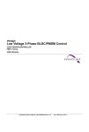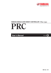
1
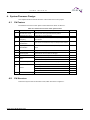
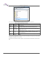
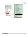
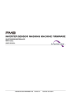
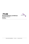
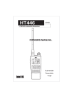
The following document contains information on Cypress products. Although the document is marked with the name “Spansion” and “Fujitsu”, the company that originally developed the specification, Cypress will continue to offer these products to new and existing customers. Continuity of Specifications There is no change to this document as a result of offering the device as a Cypress product. Any changes that have been made are the result of normal document improvements and are noted in the document history page, where supported. Future revisions will occur when appropriate, and changes will be noted in a document history page. Continuity of Ordering Part Numbers Cypress continues to support existing part numbers. To order these products, please use only the Ordering Part Numbers listed in this document. Worldwide Sales and Design Support We look forward to partnering with you to provide solutions that will help make your systems successful. Cypress maintains a worldwide network of offices, solution centers, manufacturer’s representatives, and distributors. To find the office closest to you, visit us at Cypress Locations. About Cypress Cypress (NASDAQ: CY) delivers high-performance, high-quality solutions at the heart of today’s most advanced embedded systems, from automotive, industrial and networking platforms to highly interactive consumer and mobile devices. With a broad, differentiated product portfolio that includes NOR flash ® memories, F-RAM™ and SRAM, Traveo™ microcontrollers, the industry’s only PSoC programmable ® system-on-chip solutions, analog and PMIC Power Management ICs, CapSense capacitive touch® sensing controllers, and Wireless BLE Bluetooth Low-Energy and USB connectivity solutions, Cypress is committed to providing its customers worldwide with consistent innovation, best-in-class support and exceptional system value. PMSM Servo Motor Speed Control User Manual 32-bit ARM Cortex-M4F based Microcontroller MB9BF568x Series and S6E2HG Series User Manual Jan 26, 2015, AN709-00011-1v0-E 1 U S E R M A N U A L Table of Contents 1. 2. 3. 4. 5. 6. 7. 8. Introduction ..................................................................................................................................... 4 1.1 Purpose …………………………………………………………………………………………….4 1.2 Definitions, Acronyms and Abbreviations ............................................................................ 4 1.3 Document Overview ............................................................................................................ 4 System Hardware Environment ...................................................................................................... 5 Development Environment ............................................................................................................. 6 System Firmware Design ............................................................................................................... 7 4.1 FW Feature ......................................................................................................................... 7 4.2 FW Structure ....................................................................................................................... 7 4.3 Files Description ................................................................................................................ 10 4.4 FW Control Flow................................................................................................................ 11 Interrupt Function ......................................................................................................................... 12 5.1 Function List ...................................................................................................................... 12 5.2 Interrupt Priority Setting..................................................................................................... 12 5.3 Interrupt Generation .......................................................................................................... 13 5.3.1 MFT .................................................................................................................. 13 5.3.2 Encoder Capture .............................................................................................. 13 5.3.3 DTTI ................................................................................................................. 14 Demo System ............................................................................................................................... 15 6.1 Demo System Introduction ................................................................................................ 15 6.1.1 Hardware Connection ....................................................................................... 16 6.2 Motor Debug ..................................................................................................................... 17 6.2.1 FW Interface Configuration............................................................................... 18 6.2.2 Encoder Check ................................................................................................. 21 6.2.3 Run Motor......................................................................................................... 22 6.2.4 Speed Acceleration and Deceleration .............................................................. 24 6.3 Troubleshooting ................................................................................................................ 24 6.3.1 Protection ......................................................................................................... 24 Additional Information ................................................................................................................... 25 Reference Documents .................................................................................................................. 26 Figures Figure 4-1: Structure of FW ........................................................................................................................ 8 Figure 4-2: Sub-files in Each Layer ............................................................................................................ 9 Figure 4-3: Servo motor FW Architecture ................................................................................................. 10 Figure 4-4: Diagram of the Control Flow ................................................................................................... 11 Figure 5-1: Interrupt Priority Setting ......................................................................................................... 12 Figure 5-2: Free Run Timer Interrupt ........................................................................................................ 13 Figure 5-3: Encoder Capture with Base-Timer ......................................................................................... 13 Figure 5-4: DTTI Interrupt ......................................................................................................................... 14 Figure 6-1: System Connection ................................................................................................................ 15 Figure 6-2: Encoder Signal Line Connection ............................................................................................ 16 Figure 6-3: Motor Line Connection ........................................................................................................... 16 Figure 6-4: JTAG Line Connection ........................................................................................................... 17 Figure 6-5: AC Plug .................................................................................................................................. 17 Figure 6-6: Open the Workspace ............................................................................................................. 18 Figure 6-7: Interface File Diagram ............................................................................................................ 18 Figure 6-8: Macro Define for encoder....................................................................................................... 21 Figure 6-9: Download and debug by J-link ............................................................................................... 23 Figure 6-10:Motor Run by J-link ............................................................................................................... 23 Figure 6-11: Motor in Running Status ....................................................................................................... 23 2 Jan 26, 2015, AN709-00011-1v0-E U S E R M A N U A L Tables Table 3-1: MCU Development Environment ............................................................................................... 6 Table 4-1: Feature List of servo motor speed control ................................................................................. 7 Table 4-2: Directory Description of Project ................................................................................................. 8 Table 4-3: File Description of Project ........................................................................................................ 10 Table 5-1: System Used Interrupt Function .............................................................................................. 12 Table 6-1: Encoder Connection ................................................................................................................ 16 Table 6-2: Sample Resistor, Amplification, Carrier Frequency and Dead-Time ........................................ 19 Table 6-3: Current PID and Speed PID .................................................................................................... 19 Table 6-4: Motor Startup Parameters ....................................................................................................... 20 Table 6-5: Motor Close-Loop Parameters................................................................................................. 20 Table 6-6: Protection Parameters ............................................................................................................. 21 Table 6-7: Brake Enable or Disable Flag .................................................................................................. 21 Table 6-8: Global Structure for Encoder Check ........................................................................................ 22 Table 6-9: Running Status by the Command Speed................................................................................. 24 Jan 26, 2015, AN709-00011-1v0-E 3 U S E R M A N U A L 1. Introduction 1.1 Purpose This user manual describes the speed-control solution of the SPANSION servo motor and how to use the inverter servo motor FW library. This document will help you quickly learn how to build a servo motor project and how to debug the motor with SPANSION inverter servo motor FW library. The document introduces the basic information of whole servo motor control system, including hardware, firmware, initial functions, basic motor setting functions and FOC drive modules. When you have understood the provided information, you can get an overview of a whole servo motor project. And you can run a motor following the demo project step. 1.2 1.3 Definitions, Acronyms and Abbreviations API - Application Programming Interface FOC - Field Oriented Control FW - Firmware HW - Hardware I/O - Input and output CW - Clockwise CCW - Counter clockwise Document Overview The rest of document is organized as the following: Chapter 2 explains System Hardware Environment Chapter 3 explains Development Environment Chapter 4 explains System Firmware Design Chapter 5 explains Interrupt Function Chapter 6 explains Demo System Chapter 7 explains Additional Information Chapter 8 explains Reference Documents 4 Jan 26, 2015, AN709-00011-1v0-E U S E R M A N U A L 2. System Hardware Environment The below shows the brief information of MCU used in servo motor inverter board. CPU chip: Spansion MB9BF568R. CPU Frequency: 160MHz. MCU pin number: 120pin. RAM Space: 128Kbytes. Code Space: 1024Kbytes. Demo HW version: FSDC-FM3-314-1-0015-01 + FSDC-FM4-560-2-071200050 Jan 26, 2015, AN709-00011-1v0-E 5 U S E R M A N U A L 3. Development Environment Table 3-1: MCU Development Environment Name Description IAR bedded Workbench FW code edit , compile and 7.3 debug J-Link Manufacturer Remark N/A N/A N/A Debug and Load FW by JTAG N/A N/A Flash download program N/A N/A Source Insight Source code edit N/A N/A Editor Eclipse Source code edit N/A N/A Editor SPANSION FLASH LOADER 6 Part Number N/A N/A Jan 26, 2015, AN709-00011-1v0-E U S E R M A N U A L 4. System Firmware Design This chapter introduces the FW structure of the inverter servo motor project 4.1 FW Feature The features of the servo motor speed control solution are shown in Table 4-1. Table 4-1: Feature List of servo motor speed control No Feature Description 1. Encoder Zero-Check Match encoder zero signal with electrical position 2. Hardware Self -check Check offset of current sampling Adjustable Carrier Carrier frequency can be set by the corresponding variable in Frequency user interface 4. Rapid speed acceleration Motor can be accelerated from 0rpm to 5000rpm within 200ms 5. Rapid speed deceleration Motor can be decelerated from 5000rpm to 0rpm within 6. FOC Control Using FOC control algorithm 7. Speed regulate This function is used to speed up or slow down a motor by the command from host via UART or debugger 8. Speed precision Accurate speed controlling with less than 1% target error. 9. Brake 3. 10. Current sample Remark 200ms Stop motor by brake down Slow down a motor by brake Three-phase hall-sensor for current sampling DC voltage protect 11. A/D offset protect Protect Lock rotor protect Over Current Protect 12. 4.2 Bi- directional rotating Motor can run in both directions. FW Structure There are 5 layers in the FW structure of IAR, which are shown in Figure 4-1. Jan 26, 2015, AN709-00011-1v0-E 7 U S E R M A N U A L Figure 4-1: Structure of FW The C source and Header files which are included in each layer are shown in Table 4-2 Table 4-2: Directory Description of Project Layer Folder Description global h01_global, s01_global MCU system file driver h02_driver, s02_driver MCU register setting function such as GPIO, interrupt, MFT, AD module h03_module, s03_module Algorithm folder for basic motor control such as FOC frame transform , SVPWM, math, PID, filter app h04_app, s04_app user h05_user, s05_user Application folder for the files of application functions such as speed and position generator by hall sensor, protection, motor start-up, field weaken, brake and etc. Customer interface folder for the files for motor Configuration and HW setting Note: if you want to quickly start the motor, you can refer to the setting for user layer at 6.2.1FW Interface Configuration and chapter 5 Interrupt Function. The sub-files in each folder are shown in Figure 4-2, and the structure of header files is the same with C files. 8 Jan 26, 2015, AN709-00011-1v0-E U S E R M A N U A L Figure 4-2: Sub-files in Each Layer Jan 26, 2015, AN709-00011-1v0-E 9 U S E R M A N U A L The relationship between each layer is shown as the diagram in Figure 4-3. User Layer User interface Main program entrance Interrupt vectors Initialization Int. event App Layer Motor Start-up Motor Speed Set Brake Speed Calculation Current sample Voltage and Current Limit A/D Offset Protect Over Current Protect Field-weaken Lock Rotor Protect Voltage Protect Encoder zero check Dead-time compensation Module Layer Coordinate transformation Math PID Regulator Filter SVPWM Drive Layer Global Layer Figure 4-3: Servo motor FW Architecture 4.3 Files Description The detailed descriptions for each file are shown as Table 4-3. Table 4-3: File Description of Project Folder File Description s01_global N/A No files temporarily. S02_driver N/A coordinate_transfrom.c No files temporarily. FOC axis convert filter.c math.c One order low pass filter The math module including the function such as SQRT,COS,SIN s03_module 10 Jan 26, 2015, AN709-00011-1v0-E U S E R M A N U A L pid_regulation.c svpwm.c The PID module for current and speed PI The SVPWM module adc_sample.c brake.c The ADC process module based on the ADC ISR The brake module including motor stop by brake limitation.c Dead-time compensation.c The FOC current and voltage limitation module Dead-time compensation module() motor_ctrl.c The main file of the motor control including the main function of FOC process of motor and the start/stop function of motor motor_startup_encoder.c The motor start-up zero-checking observer_encoder.c protect.c The Position Calculate module by encoder The Protect module speed_calculate.c qprc_zero_seach The Speed Calculate module Search encoder zero signal module customer_interface.c main.c The motor parameter setting Main function isr.c init_mcu.c MCU interrupt vector list Initialize MCU peripheral functions Startup_mb9xfxxx.s MCU startup file s04_app s05_user module with encoder after 4.4 FW Control Flow The control flow for the motor is shown as Figure 4-4. There are 4 interrupts that are red highlighted for the motor FOC control, hall capture, AD converter. The timer events are executed in the end-less loop and the timers are generated in the zero detection interrupt ‘ISR_MFT_FRT’ of the free run timer 0. End-less loop in Main.c Start Initialize peripheral Current U\V\W sample Feed watchdog DC bus sample and calculate Motor Start/Stop ISR_ADC_unit0 ISR_MFT_FRT FOC control Current restoration PID Speed &Position Generate SVPWM Other Algorithm Protection(High Priority) Figure 4-4: Diagram of the Control Flow Jan 26, 2015, AN709-00011-1v0-E 11 U S E R M A N U A L 5. Interrupt Function 5.1 Function List Table 5-1: System Used Interrupt Function Prototype Description Remark __root void HWD_Handler(void) __root void Swd_IsrHandler (void) The HW watch dog ISR The software watch dog ISR s05_user/isr.c s05_user/isr.c __root void Mft0_Frt0_ZeroIsrHandler (void) __root void Mft0_Wfg_IsrHandler (void) The MFT zero detect ISR for the motor control The HW over-current ISR s05_user/isr.c s05_user/isr.c __root void Adc_0_IsrHandler (void) The ADC unit0 ISR, trigger at the zero point for the 3 shunts s05_user/isr.c 5.2 Interrupt Priority Setting Each interrupt priority can be set by the function ‘void InitMcu_Nvic(void)’ which is located at the file ‘s05_user/init_mcu.c’. Users are not recommended to modify it. The priority used for motor control is shown in Figure 5-1. The lower the number is, the higher the priority is. Figure 5-1: Interrupt Priority Setting 12 Jan 26, 2015, AN709-00011-1v0-E U S E R 5.3 M A N U A L Interrupt Generation The diagram of the interrupt used for the motor control is briefly introduced in this section. 5.3.1 MFT The multifunction timer is used to generate the interrupt for the motor control algorithm execution, and trigger the AD sample at the zero point. ISR_MFT_FRT Free run timer 0, UP/DOWN mode, PWM cycle: 66.7 µs, 15K Hz Trigger AD unit0 and FOC interrupt A/D unit0: sample U, V, W current FOC interrupt to drive motor Figure 5-2: Free Run Timer Interrupt 5.3.2 Encoder Capture The PWC timer is used to capture the encoder A/B signal and calculate pulse-width of the edge of A/B. Encoder A/B signal Voltage High or Low level One motor mechanical cycle H L Measure completion Base timer Count Over Flow Motor speed calculate and rotor phase angle core Figure 5-3: Encoder Capture with Base-Timer Jan 26, 2015, AN709-00011-1v0-E 13 U S E R M A N U A L 5.3.3 DTTI The DTTI0 is used to trigger the HW fault protection from the IPM. When the phase current is large enough to trigger the HW over-current fault, the interrupt is got and all of the drive signals for the motor control will shut off immediately. ISR_MFT_WFG IPM fault signal low voltage H L Trigger over Current Interrupt, PWM closed Figure 5-4: DTTI Interrupt 14 Jan 26, 2015, AN709-00011-1v0-E U S E R M A N U A L 6. Demo System This chapter introduces one example of inverter servo motor project and help you run a motor quickly. The primary steps are shown as following: Hardware Connection FW Interface Configuration Encoder Check Run Motor Speed Acceleration and Deceleration 6.1 Demo System Introduction The servo motor solution can be adaptive to any type of servo motor speed control which uses the PMSM or BLDC motor. The connection diagram for debugger is shown in Figure 6-1. Figure 6-1: System Connection Jan 26, 2015, AN709-00011-1v0-E 15 U S E R 6.1.1 M A N U A L Hardware Connection It is necessary to connect below 4 lines: 1. Connect motor’s encoder signal to inverter board, shown as below. Encoder port Figure 6-2: Encoder Signal Line Connection The connection of the encoder signal line follows the definition in the below table. Table 6-1: Encoder Connection Motor’s line Note: Inverter Board Circuit Port Encoder A AIN Encoder B Encoder Z BIN ZIN +5V GND Vcc GND Connection order between A and B is mixable. VCC and GND must be connected rightly, otherwise the encoder won’t work right and the motor will also not run. 2. Connect motor’s U, V, W phase lines to inverter board, shown as below. U, V, W Figure 6-3: Motor Line Connection Motor’s U, V, W line can be optionally connected to Inverter’s output U, V, W. It has no constant define. Just connect it. And it is also recommended to connect according to the UVW definition of the motor. 3. Connect JTAG to Inverter, shown as below. 16 Jan 26, 2015, AN709-00011-1v0-E U S E R M A N U A L J-Link Figure 6-4: JTAG Line Connection Note: If there is no isolator between the J-link and the HW, you must unplug the AC power and use the battery of your laptop computer 4. Connect AC power to inverter board, shown as below. AC Power Figure 6-5: AC Plug 6.2 Motor Debug After the hardware connection with the motor is completed, you can debug the new motor, as described in this section. Click the IAR program to open the IAR, and open the ‘EWW’ file of the inverter servo motor workspace at the location you’ve stored on your computer as shown in Figure 6-6. Jan 26, 2015, AN709-00011-1v0-E 17 U S E R M A N U A L Figure 6-6: Open the Workspace 6.2.1 FW Interface Configuration All of the variables reserved for the user interfaces are located in the file ‘s05_user/ customer_interface.c’ and the macro definitions are located in the file ‘h05_user/ customer_interface.h’. Figure 6-7: Interface File Diagram 6.2.1.1 UI_01 Motor Parameters Set motor pole pairs. Set it to 3 if motor with 3 pole pairs is being used. 18 Jan 26, 2015, AN709-00011-1v0-E U S E R 6.2.1.2 M A N U A L UI_02 Encoder Information QPRC_LineNumber: indicating pulses per cycle for encoder signal A or B. QPRC_times: indicating QPRC unit working mode for detecting encoder signal. This is set to 4 by default. For more information about it, you can refer to MCU peripheral manual reading chapter QPRC for PC_Mode2 setting. 6.2.1.3 UI_03 Sample Resistor, Amplification, Carrier Frequency and Dead-Time Table 6-2: Sample Resistor, Amplification, Carrier Frequency and Dead-Time Name Explanation Motor_f32IuvwSampleResistor Motor_i32IuvwAmplifierFactor Motor_i32IuvwOffsetNormal Motor_i32IuvwOffsetRange Motor_f32DeadTimeMicroSec Value Sample resistor Amplification factor ADC value for 2.5V offset Define offset range Dead-time 0.015 5.0 times 2.5V<=>2048 150 : Offset range<2048-150,2048+150> 2.5us Motor_u16CarrierFreq Carrier frequency for PWM 15000Hz Sample resistor and amplification is related to hardware board, they must be written correctly. Dead-time is depended on IPM, MOSFET or IGBT, the minimum dead-time can be found in its datasheet. Carrier frequency can be rewritten as requirement. 6.2.1.4 UI_04 Current PID and Speed Loop PID Table 6-3: Current PID and Speed PID Name Explanation Motor_f32LowSpdKi Speed loop integration parameters when speed lower than Motor_u16ChgPiSpdHz Motor_f32LowSpdKP Motor_f32Dki Speed loop proportion parameters when speed lower than Motor_u16ChgPiSpdHz Current loop integration parameters in D-axis Motor_f32Dkp Motor_f32Qki Current loop proportion parameters in D-axis Current loop integration parameters in Q-axis Motor_f32Qkp Motor_f32Skp Current loop proportion parameters in Q-axis Speed loop integration parameters when speed Jan 26, 2015, AN709-00011-1v0-E These parameters are not fixed. Instead, they depend on motors and systems. Tune these parameters when changing motor. 19 U S E R M A N U A L Motor_f32Skp higher than Motor_u16ChgPiSpdHz Speed loop proportion parameters when speed higher than Motor_u16ChgPiSpdHz Motor_u16ChgPiSpdHz Switch speed loop PI parameters 6.2.1.5 UI_05 Motor Startup Parameters Table 6-4: Motor Startup Parameters Name Motor_i16Q8_OrientIqRef Explanation Set current for orientation Motor_f32OrientTime Motor_u16OpenLoopSpdIncHz Set orientation time Speed acceleration rate in open loop Motor_u16OpenLoopSpdInitHz Motor_u16OpenLoopSpdEndHz Initial mechanical speed in open loop Target mechanical speed in open loop Value Q8(1.0): 1A 1.5s 1Hz/𝑠 2 0Hz(0rpm) 1Hz(60rpm) Motor_u16OpenLoopLoopIqRef Set current in open loop stage Q8(2.0):2A Current setting in orientation and open loop stage is related to motor electrical parameter. Ensure that not exceeding motor rated current. 6.2.1.6 UI_06 Motor Close-Loop Parameters Table 6-5: Motor Close-Loop Parameters Name Value Initial target speed when getting in close loop 0Hz(0rpm) RotationFlg Motor_i16Q8_CloseLoopIsMax Initial rotation direction Maximum peak value for phase current CW or CCW Q8(2.5): 2.5A Motor_i16Q8_CloseLoopIqRefMax Motor_u16SpdMax Maximum value for q-axis Maximum rotating mechanical speed Q8(2.5): 2.5A 5000rpm Motor_u16SpdMin Motor_f32SpdAccelerationHz Minimum rotating mechanical speed Acceleration rate -5000rpm Motor_f32SpdDecelerationHz Deceleration rate 400Hz/𝑠 2 6.2.1.7 20 Explanation Motor_u16CloseLoopTargetSpdHz 600Hz/𝑠 2 UI_07 Protection Parameters Jan 26, 2015, AN709-00011-1v0-E U S E R M A N U A L Table 6-6: Protection Parameters Name Motor_i16Q8CurrentMax Explanation Soft current protection happens when peak of current is higher than this value Value Q8(3.5): 3.5A Motor_u16OverCurrentTimeSec Define times of current continuously overpassing Motor_i16Q8CurrentMax. When times of overpassing higher than Motor_u16OverCurrentTimeSec, soft-over-current protection happens. 1 time Define over-voltage protection point Define under-voltage protection point 400V 200V Motor_u16VbusMax Motor_u16VbusMin Motor_ErrorTime 6.2.1.8 Time for error flag maintaining. Motor error flag will be set, and will be cleared after Motor_ErrorTime. 10s UI_08 Brake Enable Table 6-7: Brake Enable or Disable Flag Name Explanation Motor_BrakeCtrlEn 6.2.2 Switch on or off controlling for fast braking function Value 0:disable fast braking when target-speed is set to 0 to stop motor running 1:enable fast braking when target-speed is set to 0 to stop motor running Encoder Check When the basic setting has been finished, the encoder information (zero-position A/B order) can be self-check by the encoder check module. Here take one servo motor for example. And if the encoder information has been known, this section can be ignored and the motor can be normal started now and taken the reference at section 0 Modify “SWAPBIT” definition in “hardware_config.h”, set it the same value as “Qprc_RunPars .i8_Swapbit”. Modify “QPRC_ZERO_ANGLE” definition in “hardware_config.h”. Set it the same value as “Qprc_RunPars .i32Q22_AngleToZeroInx”. Redefine “ZEROMATHCEN” to 1. Encoder check is complete. Run Motor. 6.2.2.1 FW Setting Set the variable as shown Figure 6-8 to make the control system in debug mode Figure 6-8: Macro Define for encoder QPRC_ZEROMATCH = 0: set encoder searching mode. QPRC_ZEROMATCH = 1: encoder searching mode end. QPRC_SWAPBIT = 0: no-change A/B order. QPRC_SWAPBIT = 1: exchange A/B order. QPRC_ZEROANGLE: zero position. Jan 26, 2015, AN709-00011-1v0-E 21 U S E R 6.2.2.2 M A N U A L Encoder Check Run Click the debugger button to connect the J-link, and pass the global structure ‘Qprc_RunPars’ into the Live Watch in the IAR debug online. Connect PC and hardware with J-LINK, and give motor any target speed more than 0 to run motor. Wait until motor stops running, find structure “Qprc_RunPars” in file “observer_encoder.h”, and record value of variable “Qprc_RunPars .i8_Swapbit” and “Qprc_RunPars .i32Q22_AngleToZeroInx” Table 6-8: Global Structure for Encoder Check Encoder A/B order bit Zero-match completion flg Zero-position angle Estimated speed by encoder Modify “SWAPBIT” definition in “hardware_config.h”, set it the same value as “Qprc_RunPars .i8_Swapbit”. Modify “QPRC_ZERO_ANGLE” definition in “hardware_config.h”. Set it the same value as “Qprc_RunPars .i32Q22_AngleToZeroInx”. Redefine “ZEROMATHCEN” to 1. Encoder check is complete. 6.2.3 Run Motor When the encoder angle has been checked, the motor can be started for the demo show. (1) Check the basic motor and HW parameter setting in the user interfaces. If the setting does not match the real HW and washing machine parameter, there will be an unexpected running error in the motor running. (2) Compile project and download program to inverter board by the J-link. ① Click button A that is shown in Figure 6-9 to connect the J-link and download the FW into the MCU, ② Click button B shown in Figure 6-10 to run the FW online. ③ You can enter the none-zero speed value to start the motor in the structure that is shown as C in Figure 6-11. For example, when the variable ‘MotorCtrl_stcRunPar.i16TargetSpeedRpm = 90’ by your online input, the speed of the servo motor will run to 90rpm. Do not click button D in Figure 6-11 while motor in running status. 22 Jan 26, 2015, AN709-00011-1v0-E U S E R M A N U A L A Figure 6-9: Download and debug by J-link B Figure 6-10:Motor Run by J-link D C Figure 6-11: Motor in Running Status Jan 26, 2015, AN709-00011-1v0-E 23 U S E R M A N U A L Table 6-9: Running Status by the Command Speed MotorCtrl_stcRunPar.i16TargetSpeedRpm >0 Running Status CW <0 =0 CCW Stop Note: (4) Watch the important variable “MotorCtrl.i32Q8_EstimWmHzf” to check whether motor is achieved the command speed and running speed is stable. 6.2.4 Speed Acceleration and Deceleration After run motor normally, you can run motor in any speed (-5000rpm ~ 5000rpm). The negative or positive indicates rotational direction. 6.3 Troubleshooting 6.3.1 Protection When the motor is stopped without the normal stop command, the protection fault may appear, you can see the value of the variable ‘MotorCtrl_stcRunPar.u16FaultCode’ in the watch window and the code is assigned by the bit OR operation. The fault codes for each protection are shown as below. You can match the value with these fault codes to find what protection is performed. #define NORMAL_RUNNING 0x00 //no error #define OVER_VOLTAGE 0x01 //DC bus over-voltage #define UNDER_VOLTAGE 0x02 //DC bus under-voltage #define SW_OVER_CURRENT 0x04 //over-current #define MOTOR_OVER_CURRENT 0x08 //over-current of HW #define MOTOR_LOSE_PHASE 0x10 //motor lose phase #define NO_CONECT_COMPRESSOR 0x20 //no motor connected #define AD_MIDDLE_ERROR 0x40 //current sample 2.5V offset error #define SF_WTD_RESET 0x80 //FW watch dog reset #define MOTOR_LOCK 0x100 //motor lock #define UNDEFINED_INT 0x200 //undefined interrupt #define HW_WTD_RESET 0x400 //HW watch dog reset There may be different processing logic about the protection. The fault code may not be cleared except the DC bus voltage protection for the inverter DEMO. That is the FW may not run again when the protection fault happens. You can access the variable ‘Motor_stcRunParam.u16FaultCode’ to make your own protection processing logic. 24 Jan 26, 2015, AN709-00011-1v0-E U S E R M A N U A L 7. Additional Information For more Information on Spansion semiconductor products, visit the following websites: English version address: http://www.spansion.com/Products/microcontrollers/ Chinese version address: http://www.spansion.com/CN/Products/microcontrollers/ Please contact your local support team for any technical question America: [email protected] China: [email protected] Europe: [email protected] Japan: [email protected] Other: http://www.spansion.com/Support/SES/Pages/Ask-Spansion.aspx Jan 26, 2015, AN709-00011-1v0-E 25 U S E R M A N U A L 8. Reference Documents 26 Jan 26, 2015, AN709-00011-1v0-E U S E R M A N U A L AN709-00011-1v0-E Spansion Application Note FM4 Family 32-BIT MICROCONTROLLER PMSM Servo Motor Speed Control User Manual Jan 2015 Rev. 1.0 Published: Edited: Jan 26, 2015, AN709-00011-1v0-E Spansion Inc. Communications 27 U S E R M A N U A L Colophon The products described in this document are designed, developed and manufactured as contemplated for general use, including without limitation, ordinary industrial use, general office use, personal use, and household use, but are not designed, developed and manufactured as contemplated (1) for any use that includes fatal risks or dangers that, unless extremely high safety is secured, could have a serious effect to the public, and could lead directly to death, personal injury, severe physical damage or other loss (i.e., nuclear reaction control in nuclear facility, aircraft flight control, air traffic control, mass transport control, medical life support system, missile launch control in weapon system), or (2) for any use where chance of failure is intolerable (i.e., submersible repeater and artificial satellite). Please note that Spansion will not be liable to you and/or any third party for any claims or damages arising in connection with above-mentioned uses of the products. Any semiconductor devices have an inherent chance of failure. You must protect against injury, damage or loss from such failures by incorporating safety design measures into your facility and equipment such as redundancy, fire protection, and prevention of over-current levels and other abnormal operating conditions. If any products described in this document represent goods or technologies subject to certain restrictions on export under the Foreign Exchange and Foreign Trade Law of Japan, the US Export Administration Regulations or the applicable laws of any other country, the prior authorization by the respective government entity will be required for export of those products. Trademarks and Notice The contents of this document are subject to change without notice. This document may contain information on a Spansion product under development by Spansion. Spansion reserves the right to change or discontinue work on any product without notice. The information in this document is provided as is without warranty or guarantee of any kind as to its accuracy, completeness, operability, fitness for particular purpose, merchantability, non-infringement of third-party rights, or any other warranty, express, implied, or statutory. Spansion assumes no liability for any damages of any kind arising out of the use of the information in this document. ® ® ® TM TM Copyright © 2014 Spansion. All rights reserved. Spansion , the Spansion logo, MirrorBit , MirrorBit Eclipse , ORNAND and combinations thereof, are trademarks and registered trademarks of Spansion LLC in the United States and other countries. Other names used are for informational purposes only and may be trademarks of their respective owners. 28 Jan 26, 2015, AN709-00011-1v0-E