1
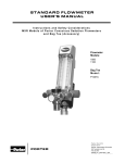
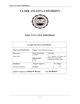
MXR FLOWMETER
USER’S MANUAL
Instructions and Safety Considerations
MXR Models of Porter Conscious Sedation Flowmeters
And Bag Tee (Accessory)
Wall Mount Models:
2000
2000-OS
3000
3000-OS
Bag Tee Models:
P1407A
P2407A
P1407B
CABINET MOUNT MODELS
Cabinet Mount Models:
2050W, 2055W, 2060W, 2066W, 2065W, 2070W, 3065W and 3066W
Porter Flowmeter Model No.:
Serial Number:
Table of Contents
Features and Specifications.................................................................................... 2
Partial Listing of Reference Materials ..................................................................... 2
Warnings and Precautions...................................................................................... 3
Cross Lines Warning............................................................................................... 4
Do not Allow Crossed Lines to Defeat Equipment Safety Features Illustration ...... 5
Safety: ADA Guidelines / NFPA Codes ................................................................. 6
Intended Use – Flowmeter for Analgesia Delivery System ..................................... 6
Use Scavenging...................................................................................................... 6
Gas Supply Connection .......................................................................................... 6
Monthly Leak Check ............................................................................................... 6
Flowmeter Mounting Options .................................................................................. 7 - 8
Wall Mount .................................................................................................. 7
Cabinet Mount............................................................................................. 7
Slide Away .................................................................................................. 7
Mobile Stand and E-Stand .......................................................................... 8
MXR Flush Mount Flowmeter ................................................................................. 8
Oral Surgery MXR Model 2000-OS......................................................................... 8
Flowmeter Accessories........................................................................................... 8 – 9
Three Liter Bag ........................................................................................... 8
Positive Pressure / Demand Valve.............................................................. 8
Gas Scavenging Breathing Circuit .............................................................. 9
Automatic Vacuum Switch (AVS) ................................................................ 9
In-Line Vacuum Control Kit ......................................................................... 9
Flowmeter Features ................................................................................................ 10
Safety Feature Checks ........................................................................................... 11
Nitrous Oxide Failsafe System (Check Before Each Use) .......................... 11
Concentration Control Knob Valve (Check Monthly) .............................................. 11
Power Oxygen Flush (Check Monthly) ................................................................... 12
Quick Test to Check 3 Liter Bag / Rubber Goods for Leaks ....................... 12
Bag Tee .................................................................................................................. 12 – 13
Non-Rebreathing Valve (Check Monthly).................................................... 13
Emergency Air Valve (Check Monthly)........................................................ 13
Monthly Calibration Check ...................................................................................... 13
Directions for Use ................................................................................................... 14 – 15
Basic Delivery Technique............................................................................ 15
Maintenance and Service ....................................................................................... 15
Cleaning Methods ................................................................................................... 15
Troubleshooting Chart ............................................................................................ 16
Warranty and Returns............................................................................................. 17
1
MXR FLOWMETER
FEATURES AND SPECIFICATIONS
Flow meter
T yp e
Upright
Model
N u mb e r ( s )
2000, 2000-OS, 3000 & 3000-0S
Maximum N2O
Concentration
70%
Cabinet Mount
2050W, 2055W, 2060W, 2065W, 2070W & 3065W
65%
Special
Cabinet Mount
2066W & 3066W
50%
Flow meter: Indicates flow in L/min and percent N2O of total flow with accuracy of ± 5%.
Includes Diameter Index Safety System (DISS) for N2O and O2 connectors.
Flow meter Tubes: Direct reading flow tubes for Oxygen and Nitrous Oxide for
accurate, visual flow readings.
Dual Seal Fail-Safe:
Automatically reduces N2O if O2 is shut off or pressure is
reduced
Gas Control Block: One-piece, solid aluminum construction. Eliminates internal gas
leaks.
Gas Flow Adjustment Knobs: Control knob-type knobs for quick, accurate, one-hand
adjustment of gas flows.
E m e r g e n c y A i r V a l ve : A u t o m a t i c a l l y p r o v i d e s p a t i e n t w i t h a m b i e n t A i r i f g a s f l o w i s
interrupted for any reason.
N o n - r e b r e a t h i n g C h e c k V a l ve :
Prevents rebreathing of used gases and guards
against CO2 build-up.
P o s i t i ve O N / O F F S w i t c h : E l i m i n a t e s p o s s i b i l i t y o f a c c i d e n t a l l y l e a v i n g t h e m a c h i n e
on. Color- coded for Oxygen.
O x yg e n P o w e r F l u s h B u t t o n : P r o v i d e s e x t r a d e l i v e r y o f O 2 . B u t t o n i s a c c e s s i b l e t o
override all other gas flows and deliver 100% O2. Color-coded for Oxygen.
Flow Control knob: Total flow adjustment knob which controls flow of both N2O and
O2 at any desired concentration.
Total flow can be adjusted without affecting
concentration. Includes posi-stop needle valves for adjustment of all flows—prevents
damage to valves and seats.
O x yg e n Q u i c k C o n n e c t :
Facilitates connection of resuscitation equipment to the
c e n tr a l s ys te m .
PARTIAL LISTING OF REFERENCE MATERIAL
1
Handbook of Nitrous Oxide and Oxygen Sedation – Morris Clark • Ann Brunick
Dentists’ Desk Reference: Materials, Instruments & Equipment - American Dental
As s o c i a ti o n
Relative Analgesia in Dental: Inhalation Analgesia and Sedation with Nitrous Oxide Harry Langa, D.D.S.
Conscious - Sedation in Dental Practice - C. Richard Bennett
Sedation - A Guide to Patient Management - Stanley F. Malamed
The Practical Use Nitrous Oxide - Oxygen Conscious Sedation - Robert E. Hamric,
D.M.D
2
IMPORTANT:
READ MANUAL COMPLETELY BE F O R E O P E R A T I N G T H I S D E V I C E
Basic delivery technique is described. Also, this manual contains instructions on periodically
required checks to be performed by the user. These checks are necessary to insure the proper
performance of this device and its safety features. Retain this manual for future reference.
WARNINGS AND PRECAUTIONS
These warnings and precautions are to help
you to understand how to safely operate the
MXR Flowmeter. A WARNING alerts you to a
possible hazard to people. A CAUTION alerts
you to the possibility of equipment damage.
WARNING: Do not use this device for the
administration of general anesthesia or as a
part of, or in conjunction with, a general
anesthesia administration system.
WARNING: Dental workers are exposed to
N2O during administration of N2O/O2 conscious
sedation analgesia. NIOSH has recommended
that exposures should be minimized. Contact
NIOSH (1-800-35-NIOSH) to receive NIOSH
Publications on Control of Nitrous Oxide in
Dental Operatories.
Exposure can be
minimized by effective controls.
National
Institute for Occupational Safety and Health
(NIOSH) publications state that controls,
including System Maintenance, Ventilation and
Work Practices can effectively reduce N2O
concentrations in dental operations.
Your
flowmeter accessory Porter scavenger system
is an important part of the system of controls.
WARNING:
Porter Instrument equipment
utilizes the cross+protection system. The
flexible hose and connectors that connect to
the flowmeter are diameter indexed; 3/8” O.D.
for Nitrous Oxide and ½” O.D. for Oxygen. The
cross+protection system is designed to
prevent misconnection of Oxygen and Nitrous
Oxide piping.
DO NOT ATTEMPT TO
CHANGE
THE
DIAMETERS
OR
CONNECTORS OF THE FLOWMETER!
Tampering with the cross+protection system
constitutes acceptance of liability by the
installer.
WARNING: New or modified installations properly connected gas pipelines are
absolutely essential to patient safety. The
dealer or contractor should provide written
documentation that all gas pipelines are
connected properly and that the system has
been pressure tested prior to use. While this is
a good business practice, it is important that
the user verify by their own test, independent
of the dealer or contractor, that all gas
pipelines are connected correctly prior to using
the system. The ultimate responsibility of
assuring that lines are not crossed rests
with the user.
WARNING:
During any power outage,
remember to turn OFF the flowmeter and
manually turn OFF the tank valves.
With
centralized, electrically powered gas systems,
if gas was flowing when the power went out
and the flowmeter is left ON, gas will be flowing
when the power is restored.
CAUTION: Federal law requires this device for
use by or on the order of a physician or dentist.
CAUTION: Always use clean, dry medical
grade gases. Introduction of moisture or other
contaminants into this device may result in
defective operation.
CAUTION: Do not attempt to repair, alter or
calibrate this device. Unauthorized repair,
alteration or misuse of this device is likely to
adversely affect the performance and will void
the warranty.
CAUTION: Never oil or grease any part of this
system (minimize fire or explosion potential).
3
WARNING:
NEW OR MODIFIED INSTALLATIONS
ALWAYS ASSURE THAT LINES ARE NOT CROSSED!
WARNING: New or modified installations - properly connected gas pipelines are absolutely essential
to patient safety. The dealer or contractor should provide written documentation that all gas pipelines are
connected properly and that the system has been pressure tested prior to use. While this is a good
business practice, it is important that the user verify by their own test, independent of the dealer or
contractor, that all gas pipelines are connected correctly prior to using the system. The ultimate
responsibility of assuring that lines are not crossed rests with the user.
Do not allow crossed lines to defeat the safety features of the dental flowmeter and/or
central gas supply manifold systems. Crossed lines will create a dangerous and hazardous
condition where 100% nitrous oxide will be delivered through the oxygen dental flowmeter tube and
subsequently to the patient. In addition, the resuscitator quick connect would deliver 100% nitrous
oxide to an oxygen demand valve.
Maintain patient observation during procedures. Prevent over sedation. If a patient becomes over
sedated when being delivered 100% oxygen, it is a definite indication of crossed lines. If crossed
lines are suspected, remove the nasal mask immediately and encourage mouth breathing. Deliver
pure oxygen from an oxygen demand valve only if the oxygen source is independent from the
suspected crossed lines area.
To check for crossed lines of an installed Porter Vanguard (or Sentinel) Manifold System:
1. At the manifold system (in the tank room), start the check from an operating system with 50 psi
showing on both gauges and the indicator lights turned on – electrical operation and alarms needed for
the Vanguard test. Then, turn off both oxygen tanks and leave both nitrous oxide tanks on. (For the
Sentinel, only one tank of each gas is on at a time. Turn off the one open oxygen tank, leave on the
one nitrous oxide tank, turn off the indicator lights – eliminates alarms during the Sentinel test.)
2. In the operatory, where the flowmeter is installed, flow 5 to 6 liters per minute of O2 only. Verify that the
N2O flowmeter valve is in the off position and that there is no indicated flow of N2O - by observing the
ball float resting at the bottom of the glass N2O flow tube.
This action will bleed the oxygen copper tubing lines (1/2” OD) from the manifold, through the office walls, to
the flowmeter. Note: this action does not cause a quick bleed down, as there is a fair sized volume in the
lines. O2 flow would be observed by the position of the ball float in the O2 flow tube for several minutes.
3. Rather than waiting for the O2 flow to decrease, go back to the manifold tank room and observe the O2
pressure gauge on the manifold (normally showing approximately 50 PSIG pressure). The line
pressure should start to decrease, indicating bleeding of the O2 that is no longer being replenished by
the tanks. On Vanguard systems, the alarm will beep at 40 PSIG, a switch will occur from one tank to
the second tank at 30 PSIG (increasing the gauge back to 40 PSIG). The gauge then should
eventually go down to zero.
If the O2 pressure does not go down as described above, and remains at about 50 PSIG, it indicates a
crossed lines condition.
4. If O2 pressure does not go down, proceed to the next crossed line determination check. Turn N2O
tanks off in the manifold tank room and watch the N2O gauge. Given a crossed line condition, the N2O
gauge will now go down (the Vanguard system will show a switching similar to step 2 above) — this
shows the O2 valve of the flowmeter is bleeding the crossed N2O lines. The N2O gauge will go down to
zero.
4
Do Not Allow Crossed Lines to
Defeat Equipment Safety Features
Crossed lines in wall structure piping creates
h a z a r d o f 1 0 0 % N i t r o u s O x i d e d e l i ve r y t o n a s a l
m a s k a n d O x yg e n d e m a n d va l ve w h e n F l o w m e t e r
i s s e t f o r 1 0 0 % O x yg e n r e s u l t i n g i n o ve r
sedation.
Over Sedation
5
1
2
3
The initial installation potential problem:
DISS (Diameter Index Safety System) is
modified at tank room wall when 3/8 inch
Nitrous Oxide pipe is increased to 1/2 inch
pipe size. Oxygen pipe remains at the normal
1 /2 i n c h s i z e .
Both Nitrous Oxide and Oxygen piping is
maintained at a common 1/2 inch size
throughout the building walls leading to
operatories.
At gas outlet station, the Oxygen 1/2 inch
pipe is incorrectly decreased down to the
DISS 3/8 inch size reserved for Nitrous Oxide
lines. Oxygen is fed into the Nitrous Oxide
lines.
4
5
6
At gas outlet station, the common run of 1/2 inch
Nitrous Oxide is incorrectly allowed to remain at
inch size and is then falsely connected to the DISS
outlet station. Nitrous Oxide is fed into the Oxygen
pipe for
the 1/2
1/2 inch
lines.
Dental flowmeter valve is set for 100% Oxygen only, but will
deliver 100% Nitrous Oxide because of the crossed lines.
A patient will become over sedated and may appear to fall
asleep when the flowmeter is set for 100% Oxygen.
7
An Oxygen demand valve connected to the resuscitator
quick connect of the Flowmeter will also deliver 100%
Nitrous
Oxide because of the crossed lines.
SAFETY:
ADA Guidelines: In addition to the fail-safe
and other safety features found on most
sedation machines, effective August 1976, the
following specifications were added to those
required for acceptance by the ADA Council on
Dental Materials and Devices: 1. Emergency
Air Valve; 2. Non-rebreathing Check Valve;
and 3. Resuscitator Quick Connect.
In addition, the ADA Council requires that: 1.
The gas storage and delivery system meet the
recommendations of the National Fire
Protection Association (NFPA); 2. The system
be installed by a competent supplier of gases
and equipment.
NFPA Codes: To assure safe operation and
conformation to local fire codes, Porter
Instrument Nitrous Oxide Sedation Systems
meet or exceed the guidelines established by
the National Fire Protection Association for
Nonflammable Medical Gas Systems, NFPA
99. Copies of NFPA 99 or portions thereof
may be obtained by writing to National Fire
Protection Association, Batterymarch Park,
Quincy, MA 02269-9904 USA or call: 1-800344-3555
INTENDED USE:
Flowmeter for Analgesia
Delivery System
This device is intended for patient use by an
attending physician or dentist properly trained
in its use. Porter Instrument recommends the
user be thoroughly familiar with the use of
Nitrous Oxide - Oxygen Conscious Sedation
for patient analgesia and be properly trained in
its administration prior to using this product.
For training requirements on the administration
of Nitrous Oxide - Oxygen Conscious
Sedation, contact the appropriate regulatory
authority in your country, state, or province.
Training is recommended to provide a
practical, hands-on capability and an
understanding of the behavioral aspects of
Nitrous Oxide Sedation and will complement
the safety features of this device.
USE SCAVENGING
Monitor for N2O in the operatory to insure that
controls are effective in achieving low levels
of ppm (parts per million) exposure. Contact
your Porter dealer for details on monitors and
testing.
GAS SUPPLY CONNECTION
After installation of the flowmeter, connect the
nitrous oxide and oxide supply lines to the
Diameter Indexed Safety System (DISS)
fittings located on the back of the flowmeter
unit. It is important that the regulators for
both gases be set to give pressures in the
range of 50 PSIG ±2 PSIG.
Confirm the absence of leaks at pressure
connections on the unit. Bubbles will appear
at leaking locations when a soap / water
solution is used.
This procedure is
recommended each time a cylinder is
changed.
MONTHLY LEAK CHECK (or if
connections to flowmeter are disconnected
and then reconnected, such as after a
flowmeter service at the factory or if the
DISS/DISS hose is replaced): Leak test the
flowmeter system for working pressure leaks.
After all hose connections are tightened, turn
the flow control knobs to the off position and
the on/off switch to the off position. Confirm
that the DISS Shut-Off Valves are in the open
position. Pressurize the sedation gas supply
lines with 50 PSI. Observe any pressure
decay after an overnight time period (5 PSI
drop allowed).
Monitor O2 gas pressures at the beginning of
each procedure to assure sufficient gas
remains in the tank to complete the
procedure.
6
Cabinet Mount Slide Model 2036: Figure C
1. Loosen knob on side of mounting block.
2. Remove mounting post from block.
3. Insert post through mounting bracket on
back of flowmeter.
4. Replace post with flowmeter attached into
mounting block.
5. Tighten knob on side of mounting block.
FLOWMETER MOUNTING OPTIONS
The Dental Flowmeter may be mounted to a
telescoping wall mount using the existing
hanger on the back of the flowmeter, or to a
mobile stand using the threaded hole at the
bottom of the failsafe block. There are various
options for mounting the flowmeter within
cabinets. The location selected for mounting
of the slide assembly should provide easy
access to reach and unobstructed view of the
flowmeter when mounted on the slide
assembly. There should be adequate space at
the rear of the flowmeter for O2 and N2O gas
delivery hoses. Contact your local
dental
dealer for mounting options.
Figure C
Solid Wall Mount – Telescoping Model 2020:
1. Remove cap from the mounting post
assembly.
2. Insert mounting post through mounting
bracket on back of flowmeter.
3. Replace cap on top of mounting post.
a. Position small diameter cap down to
allow for swivel mounting (Figure A).
b. Position small diameter cap up to fix
direction of flowmeter (Figure B).
4. Tighten screw securely.
Slide Away Mount Model 2035-1: For ease of
accomplishing the dual sliding motion, hold
the meter toward the top half and lift slightly
while sliding the arm in and out. This will
reduce the load on the slide and promote a
smoother action. Figure D
Figure A
Cap
Position
Down
Figure B
Figure D
Cap
Position
Up
7
Mobile Stand
1. Loosen thumb-screw knob.
2. Slide shaft up.
3. Insert flowmeter hole in bottom of black
failsafe block onto top of mobile stand
pole. Figure E
4. While holding the flowmeter still, screw
shaft into bottom of the flowmeter.
5. To telescope meter, loosen thumbscrew knob on side of mobile stand,
position flowmeter then retighten knob.
Figure E
MXR FLUSHMOUNT FLOWMETER
Flowmeter Models 2065W, 3065W and 2070W
have Universal connectors that are easily
switched in the field from back to bottom or
bottom to back position to suit the installation. If
the connectors are switched, the flowmeter
should be completely function tested after
installation to the user instructions contained in
this manual.
CAUTION: The position of the connectors may
be switched by an authorized Porter
representative
only. Unauthorized repair,
alteration or misuse of this device is likely to
adversely affect the performance and will void
the warranty.
ORAL SURGERY MXR MODEL 2000-OS
The oral surgery flowmeter can achieve 20 LPM
N2O maximum flow. This model includes a
special P2407A oral surgery threaded bag tee
with adapter. Accessory includes a Directional
“Y” Valve that attaches to the threaded bag tee.
(Refer to FM-631 for Directional “Y” Valve
Instructions.)
FLOWMETER ACCESSORIES
Mobile “E” Stand – Figure F
Refer to installation and instructions FM-916
for mounting flowmeter to Mobile “E” Tank
Stand.
Figure F
Three Liter Bag
Install the 3 L Reservoir Bag by sliding the
opening over the outside of the bag tee
downspout. The bag moves in and out with
each inhalation and exhalation and becomes a
visual barometer for monitoring the patient’s
respiration rate. Refer to FM-809 for User
Instructions,
Assembly,
Installation
and
Cleaning.
Positive Pressure / Demand Valve
The Porter flowmeter is equipped with a
Resuscitator Quick Connect, which allows for the
attachment of an oxygen demand valve. The
Demand Valve Resuscitator provides a fast,
simple and effective means to ventilate nonbreathing patients and provide 100% oxygen on
demand. The Resuscitator Flow rate is limited
up to 40 LPM in line with the 1992 American
Heart Association “Recommendations and
Guidelines for Resuscitation.” Refer to the User
Instructions supplied with this product
for complete details.
8
Gas Scavenger Breathing Circuit
Gas scavenger system is used to remove exhaled gases during a dental analgesia conscious
sedation procedure in a dental operatory. The breathing circuit consists of a 22mm 90° elbow
connector, fresh gas / coaxial tubing, a corrugated hose and hood assembly. Attach the nasal
inhaler to the coaxial tubing assembly using the diameter-indexed connectors. Attach one end of
the fresh gas corrugated tubing to the coaxial tubing assembly at the fresh gas “Y” connector and
the other end to the 22mm right angle adapter. Press fit the 22mm right angle adapter onto the
bag tee. Attach the 3L bag to the bottom / downspout of the bag tee. Attach the vacuum hoses to
the vacuum control source (AVS or In-line Vacuum Control Block). Refer to FM-809 for User
Instructions, Assembly, Installation and Cleaning.
5061 Connector Installation
Automatic Vacuum Switch [AVS] (Option)
The AVS is used to control the vacuum flow in the gas scavenger breathing circuit and assure
that the scavenging system is activated as soon as N2O / O2 is turned ON. Adjust the vacuum
flow using the control knob. Vacuum flow is most effective when the ball float is set within the
green bar area. Installation of AVS to Flowmeter: Screw AVS 5000 knurled seal nut down tight
onto flowmeter making sure the rubber washer is inside the seal nut. When tight, the AVS should
not rotate. Then, screw the bag tee seal nut onto the AVS. Bag tee should not rotate.
Connecting AVS to Vacuum Hoses: Attach one end of the vacuum hose to the vacuum hose “Y”
connector and the other end to the MASK port of the AVS. Attach a second vacuum hose to the
VAC port of the AVS and the other end to the vacuum source.
Porter recommends that effective scavenging can be achieved with the ball float in the green bar
area of the acrylic sight glass, however NIOSH publications conclude that higher vacuum flows of
up to 45 L/min are most effective. To meet the NIOSH recommendation of 45 L/min adjust the
ball above the green bar area.
In-line Vacuum Control Kit (Option)
The kit includes a vacuum control block with sight glass, vacuum tube holder, adapter “T” and
straight fitting. The vacuum control block can be inserted directly into the High Volume Evacuation
(HVE) line or may be placed “in-line” by cutting the vacuum hose and attaching the cut ends of
the tubing to both ends of the vacuum control block. Adjust the vacuum flow using the control
knob. Vacuum flow is most effective when the ball float is set within the green bar
area. Refer to FM-809 for User Instructions, Assembly, Installation and Cleaning.
9
FLOWMETER FEATURES
FIGURE 1
2
2
1
6
3
7
9
5
11
4
10
8
12
1 . Oxygen Flowmeter Tube i n d i c a t e s t h e
f l o w o f O 2 i n L / m i n ± 5 %.
6 . Emergency Air Valve a u t o m a t i c a l l y
provides the patient with ambient air if gas flow
is interrupted. (Check Monthly)
2 . Nitrous Oxide Flowmeter Tube
i n d i c a t e s f l o w o f N 2 O i n L / m i n ± 5 %.
7 . Non-Rebreathing Valve g u a r d s a g a i n s t
CO2 build-up and rebreathing of used gases.
(Check Monthly)
3 . Nitrous Oxide Failsafe System. D u a l seal
oxygen-piloted
valve
system
that
automatically
maintains
the
%
N2O
concentration setting with any change in the O2
flow or pressure N2O flow is proportionately
reduced if O2 is shut off or the pressure is
reduced (check before each use).
4.
Flow
Control
8. Positive On - Off Switch R e d u c e s t h e
possibility of accidentally leaving the machine
ON.
9. Power Flush p r o v i d e s e x t r a d e l i v e r y o f O 2
to the breathing bag. (Check Monthly)
Knob
controls the
combined flow of O2 and N2O (or O2 flow only
when the Concentration Control Knob is set to
0 %) .
10. O 2 Quick Connect
(left side of
machine), facilitates connection of positive
pressure/ demand valve for emergency Oxygen.
11. Bag Tee Outlet c o n n e c t s t o f r e s h g a s
5 . Concentration Control Knob c o n t r o l s
the % concentration of N2O but does not
change the O2 flow rate. (70% Maximum N2O
delivery.) (Check Monthly)
tubing.
12. 3 L Bag Connection
10
SAFETY FEATURE CHECKS
IMPORTANT:
These are safety
features, which you should routinely check
to assure proper function. If any of these
safety features are not functioning properly,
contact your Dental Dealer or Porter
Instrument and arrange for the necessary
repairs. Porter Instrument recommends the
repairs be made before reusing the device.
5. Interrupt the flow of O2. This will check
the dynamic status of the Nitrous Oxide
Failsafe System valve. This can be
done by either disconnecting the oxygen
hose from the wall or shutting off the
oxygen at the tank. The Nitrous Oxide
flow should drop as the Oxygen flow
decreases,
stopping
completely
before the Oxygen float drops to
zero.
NITROUS OXIDE FAILSAFE SYSTEM
CHECK BEFORE EACH USE
1. Set the right-hand total Flow Control
Knob to zero and set the left-hand
Concentration Control Knob to zero.
(See Figure 1-Items 4 and 5: Rotate
control knobs to stop.)
2. Be sure O2 and N2O are connected to
your MXR and line pressure for both
gases is 50 PSIG (which is standard).
3. Turn the Concentration Control Knob to
50%. There should be no flow of N2O.
This is a check of the static position of
the Nitrous Oxide Failsafe System valve.
NOTE: A momentary low flow of N2O
(about 1 L/min for about a second) may
be seen if the Concentration Control
Knob is turned to zero before turning the
Flow Control Knob to zero. This is N2O
gas trapped between the Nitrous Oxide
Failsafe System valve and the
Concentration Control Knob valve and is
a normal occurrence. No other N2O
flow should be observed.
4. With the Concentration Control Knob still
set to 50%, turn the Flow Control Knob
to achieve a flow of 3 to 4 L/min of O2.
You should observe an equal amount of
N2O flowing by gradually turning the
Flow Control Knob. (Refer to Monthly
Calibration Check on Page 13, to read
ball float on flowmeter tubes.)
WARNING
If the Nitrous Oxide Failsafe System fails to
perform as indicated, do not use this
product prior to repair. Improper function of
this safety feature may permit Nitrous Oxide
to flow independently of the flow control
knob, potentially allowing Nitrous Oxide to
flow to the patient without Oxygen.
CONCENTRATION CONTROL KNOB
VALVE – CHECK MONTHLY
Set the Concentration Control Knob to 50%,
and Flow Control Knob to 2 to 3 L/min. The
ball indicators will be at about the same
height (If not, refer to Monthly Calibration
Check section on Page 13 for the
procedure on checking the accuracy of the
meter.). Turn the Concentration Control
Knob to zero. The N2O flow should drop to
zero. You essentially perform the check at
the end of every procedure when you
oxygenate the patient with 100% O2.
11
2. With the other plastic connector, join the
two duplex hoses together making a
closed system.
POWER OXYGEN FLUSH
CHECK MONTHLY
(O2 SUPPLY PRESSURE AT 50 PSIG)
Disconnect the corrugated rubber tubing from
the bag tee outlet (Figure 1, Item 11). With
both control knob valves OFF, depress the
power (O2) flush button while blocking the
flow from the front of the bag tee. For proper
operation, the gas reservoir bag should fill
within about 5 seconds. Also test for bag /
rubber goods leak following steps 1 through
6.
3. Taking care not to fill the bag too much
(bag could burst), open the oxygen control
valve until the 3 liter bag starts to overinflate or “balloon”, then close the valve.
4. Observe the 3 liter bag for five minutes.
5. The bag should stay inflated. If so, the
test has been successful and there are no
excessive leaks. If the bag does not stay
inflated, the 3-liter bag or rubber goods
have an excessive leak. Replace any
parts that leak and retest until results are
successful.
6. Disconnect one of the duplex hoses from
the plastic connector and re-install the
nosepiece.
Figure 2
Remove
one
connector
and join
hoses
together.
CABINET MOUNT MODEL
O2 FLUSH KNOB
BAG TEE
Quick Test to Check 3 Liter Bag / Rubber
Goods for Leaks
1. With the flowmeter, bag tee and Porter
rubber goods in place, remove the
nosepiece and one of the two plastic
connectors from the Porter rubber goods.
Refer to Figure 2.
12
The Bag Tee assembly features a Nonrebreathing Valve and an Emergency Air
Intake located on the Bag Tee, which comply
with American Dental Association guidelines.
The non-rebreathing valve has a back flow
check valve, which prevents exhaled gases
from entering the breathing bag (no carbon
dioxide buildup). The emergency air intake
has a valve that allows room air to be inhaled
into the breathing circuit by the patient. A
breathing bag is attached to the metal portion
of the Bag Tee and is a reservoir bag for the
delivered analgesia gases, which when taken
together with the two valves above, becomes
the visual barometer for monitoring the
patient’s respiration rate. The bag moves in
and out with each inhalation and exhalation.
Bag Tee Installation to Flowmeter: Screw
knurled seal down tight onto flowmeter
making sure the rubber washer is inside the
seal nut. When tight, the bag tee should not
rotate.
NOTE: Fit mask to patient so inner mask is
pulled down tight secure to the face. Outer
mask should not be against the face. Vacuum
needs to be drawn into outer mask during
inhalation.
NON-REBREATHING VALVE
CHECK MONTHLY
With unit turned OFF, disconnect the
corrugated rubber tubing from the Rubber
Goods and breathe into the corrugated tubing
connected to the bag tee. You should not be
able to fill the bag with exhalation gas. If the
bag fills, the system’s Non-Rebreathing Valve is
not functioning properly and should be
replaced.
MONTHLY CALIBRATION CHECK
The MXR Flowmeter is designed to maintain
its accuracy and performance without routine
user maintenance being required.
The
flowmeter tubes and ball floats are very
resistant to accuracy changes over time such
that the direct readings of the L/min on the
scales maintain their accuracy. However, the
user can check the relative accuracies of the
% concentration and total flow valve system
by performing a simple check.
A calibration check of the % concentration
can be done by setting the % concentration
knob to 50% and the flow control knob to 3 to
4 L/min. Check to see if the tube readings
are within 0.5 L/min of each other. Servicing
is indicated if the readings are out of this
tolerance.
NOTE:
Adequate and safe conscious
sedation can be achieved even if the %
concentration is outside of the listed
tolerance, since tube scale accuracies are
maintained. However, a change in the %
concentration calibration is an indication of
overall flowmeter condition. Porter servicing
is
available,
including
recalibration,
pressure testing, internal component
checking and replacement, and final factory
testing by contacting your Authorized Porter
Dental Dealer. It is advisable, on a two (2)
year cycle, to have the MXR Flowmeter
factory checked and serviced.
Figure 3
EMERGENCY AIR VALVE
CHECK MONTHLY
-6-
With unit turned OFF, disconnect the corrugated
rubber tubing from the Rubber Goods and draw air
with your mouth through the corrugated tubing
connected to the bag tee. You should be able to
draw ambient air through the Emergency Air Valve
(the gas bag may have to fully collapse first). Air
going through the valve sounds different than
normal gas flow.
-5Read Center
Of Ball Float
-
Ball Position Shown
At 4.5 L/min
-4-3-
13
DIRECTIONS FOR USE
NOTE:
These directions detail a basic
delivery technique. However, this is not a
comprehensive description and not a
substitute for a training course that
emphasizes a practical, hands-on approach
together with instruction on safe administration
techniques. Topics covered in such a course
will include experiences of practitioners in
specific
dental
clinical
settings,
the
pharmacokinetic properties of nitrous oxide,
strategies to avoid over sedation and allow for
biological variability, and strategies to
maximize patient satisfaction.
1. Maintain patient
procedure.
observation
during
2. Turn ON unit by pushing in the ON / OFF
switch.
3. Open N2O / O2 tank valves.
4. Using Flow Control knob, set flow rate of
O2 to desired rate, keep bag about ¾’s
full.
Rotate flow control knob upwards
(clockwise) to increase flow. (See Figure
1, Item 4)
Flow Control Knob
FLOW
5. Set N2O concentration to desired level by
rotating Concentration Control Knob (See
Figure
1-Item
5)
upwards
(counterclockwise)
to
increase
concentration, as read by percentages
inscribed on the control knob. Rotate
slowly until desired level is achieved.
Practice titration* with 10% nitrous
upward movements every 60 seconds
until endpoint achieved. Patients may
typically experience relief of anxiety,
tingling in extremities, and euphoria.
Patients typically require less than 50%
nitrous.
14
Concentration Control Knob
Setting shown at 60%
50
%
60
65
N
2
O
6. Flow Control knob may be re-adjusted to
bring the total flow of gases back to
desired level, when concentration is
increased or decreased. Total flow is
equal to the sum of right and left tube
readings. (See Figure 3, to read ball float
on flowmeter tube.)
7. When
the
procedure
is
nearing
completion, amounts of N2O should be
decreased. Terminate the flow of N2O and
deliver 100% O2 to begin a minimum
postoxygenation period of 3 to 5 minutes.
Assess the patient for appropriate
recovery. Administer additional O2 if
necessary. Titration and post-procedure
100% O2 will minimize nitrous exposure to
the operatory, potential patient side
effects of lethargy, headache, or nausea,
and any potential adverse effects of
nitrous diffusion into air filled cavities.
8. When procedure is finally completed, turn
off both control knob valves for gas shut
off.
9. Place the ON / OFF switch (primary shutoff mechanism) in the OFF position. (Push
from back of ON / OFF switch.) NOTE: If
control valves are still open, gas flows
should stop at this point.
10. Turn OFF the gas supply at the tank at the
end of the day.
*NOTE: Refer to “Basic Delivery
Technique” on the following page.
*BASIC DELIVERY TECHNIQUE:
“Practice titration. Titration is a method of
administering a substance by adding
definitive amounts of a drug until an endpoint
is reached. For nitrous oxide / oxygen (N2O) /
O2) sedation, N2O is given in incremental
doses until a patient has reached a
comfortable relaxed state of sedation. The
ability to titrate N2O is a significant advantage
because it limits the amount of drug to that
which is required by the patient. If titration is
done properly, the patient does not receive
any more of the drug than is necessary. The
amount of N2O required by a patient on any
given day or time varies.”1
For information on titration, a most valuable
resource for the practitioner is the Handbook
of Nitrous Oxide and Oxygen Sedation,
written by Clark and Brunswick and published
by Mosby (www.mosby.com). This text is a
concise and contemporary guide for nitrous
oxide / oxygen administration.
IMPORTANT NOTE:
When the Concentration Control knob is
open, the Flow Control knob is closed, and
there is no N2O flow indicated in the flow
tube, the Nitrous Oxide Failsafe System will
stop the flow of N2O. However, this safety
feature should not be used as the primary
shut off mechanism. The control knobs are
for primary shut-off.
NOTE: If your unit does not operate as
described in Steps 1 through 10, please
contact your Dental Dealer or Porter
Instrument.
MAINTENANCE AND SERVICE
It is advisable, on a two (2) year cycle, to
have the MXR Flowmeter factory checked
and serviced. The Nitrous Oxide Failsafe
System is made of moving parts. Between
servicing intervals, it is advisable to safeguard
against potential malfunctions by performing
the failsafe check before each and every use
of the unit.
Safe operating techniques,
learned during your N2O - O2 Conscious
Sedation training, should always be used.
Inspect and maintain the analgesia delivery
system to prevent N2O leaks in all hoses,
connections and fittings. Repair all leaks
immediately.
CLEANING METHODS
We recommend the use of an approved
disinfectant for the dental environment for
cleaning the outside of the flowmeter and
accessories. Do not spray disinfectant directly
onto meter. Spray disinfectant into disposable
towel and wipe unit thoroughly removing
excess disinfectant to eliminate buildup.
Control knobs can be autoclaved. Remove
knobs from flowmeter. Clean using an
appropriate disinfectant. Rinse with water
then autoclave. Do not exceed 275°F for 15
minutes maximum.
1
Handbook of Nitrous Oxide and Oxygen
Sedation – Morris Clark • Ann Brunick
15
TROUBLESHOOTING CHART FOR MXR FLOWMETERS
SYMPTOM
POSSIBLE CAUSE
REMEDY
No flow of O2 or N2O when ON
/OFF switch is ON and left
knob is set at a concentration
of N2O or O2 the right knob is
rotated to give flow.
Can get O2 flow but cannot get
N2O flow.
1. O2 supply not turned ON.
With N2O concentration set,
both flows vary proportionally
with no change in flow setting.
O2 regulator is varying pipeline
pressure.
Meter will flow N2O without
any O2 flow in the O2 tube.
Failsafe failure.
Cannot get 9 ½ L/min O2 flow
with
concentration
control
knob OFF and flow control
knob full ON.
Low O2 pressure setting.
Check O2 regulator. Be sure
O2 manifold pressure is 50
PSIG ±2 PSIG. If not, call
Dealer for service.
Gas is leaking from the
ON/OFF switch.
Nick or cut in o’rings on the
ON/OFF switch.
Call Dealer for service.
Patient not feeling effects of
gases.
1. Outer mask is not
properly to patient’s face.
1. Fit so inner mask is secure
to face but outer mask is just
off face.
2. Re-adjust gas flows to
obtain acceptable bag action.
2. Machine not connected to
pipeline system.
3. Empty O2 cylinders.
1. N2O supply not turned ON.
2. N2O cylinder empty.
2. Gas flows do not
patient’s requirement.
Bag is going flat during
procedure.
fit
meet
1. Gas flows do not meet
patient’s requirement.
2. Outer mask is not fit
properly to patient’s face.
16
1. Turn O2 regulator in tank
room ON.
2. Connect to wall outlet.
3. Replace with full cylinder.
1. Turn ON N2O cylinder.
2. Replace with full cylinder.
.
Check O2 regulator. Be sure
O2 manifold pressure is 50
PSIG ±2 PSIG. If not, call
Dealer for service.
Take out of service and return
to Porter.
1. Re-adjust gas flows to
obtain acceptable bag action.
2. Fit so inner mask is secure
to face but outer mask is just
off face.
CERTIFICATE OF WARRANTY
THIS WARRANTY IS GIVEN IN PLACE OF ALL OTHER WARRANTIES,
EXPRESS
OR
IMPLIED,
OF
MERCHANTABILITY,
FITNESS
FOR
A
PARTICULAR PURPOSE OR OTHERWISE.
Under no circumstances shall Parker Hannifin Corporation be liable for incidental or consequential
damages as those terms are defined in the uniform commercial code.
Parker Hannifin Corporation, Porter Instrument Division warrants that each product or part shall be
free from defects in workmanship and materials, under normal use and with appropriate maintenance,
for one (1) year from the date of delivery to customer unless otherwise specified in writing. All rubber
and plastic parts and accessories are warranted under the same conditions for a period of ninety (90)
days from date of purchase.
No statement or claim about the product by any employee, agent, representative, or dealer of Parker
Hannifin Corporation shall constitute a warranty by Parker Hannifin Corporation or give to rise to any
liability or obligation of Parker Hannifin Corporation.
Parker Hannifin Corporation shall not be liable for any damage, injury or loss arising out of the use of
the product, whether as a result of a defect in the product or otherwise, if, prior to such damage, injury
or loss, the product was (1) damaged or misused; (2) repaired, altered or modified by persons other
than Parker Hannifin Corporation; (3) not installed in strict compliance with applicable codes and
ordinances; or (4) not installed by an authorized Parker Hannifin Corporation dealer. Parker Hannifin
Corporation's obligation for breach of this warranty, or for negligence or otherwise, shall be strictly and
exclusively limited to the repair or replacement of the product or part. This warranty shall be void on
any product on which the serial number has been altered, defaced or removed.
ORDERS All orders are to be made through authorized Parker Hannifin Corporation distributors. All
billing will be done through said distributors. Direct orders will be handled through the authorized local
dealer as determined by Parker Hannifin Corporation.
RETURNS All returned merchandise will be handled through the local Parker Hannifin Corporation
distributor. No returns will be accepted unless authorized in writing by Parker Hannifin Corporation
and accompanied by the original shipping invoice. All returns are subject to restocking charge.
Policies subject to change without notice.
The Quality System for Porter Instrument is certified to ISO 13485. The scope of
our registration is: “The design, manufacture, distribution and servicing of Dental
Flowmeters, Gas Scavenging Systems, Gas Distribution Systems and Office
Communication Systems for use in the Dental Profession.”
FM-286 Rev. T 10/10
17
REVISION HISTORY
REV.
DATE
ECN #
L
12/03/03
03-0768
M
09/14/04
N
DR
CH
APPR
Page 9 at … oxygenate the patient with
100%…add “O2”. Page 10 Title Power Oxygen
Flush was O2.Power Oxygen Flush. Update rev
and print date.
ALE
KKS
ALE
04-0787
Page 13 rewrite Cleaning Methods using
disinfectants; add Control knob can be
autoclaved.
ALE
WHK
TGT
12/06/05
05-0695
p. 1 Table of Contents add Crossed Lines; p. 4 &
5 add Warning for Crossed Lines; add Illustration
on “Do Not Allow Crossed Lines to Defeat
Equipment Safety Features and Over Sedation; p.
9 add 5061 Connector Installation; p. 13 Add
NOTE: Fit mask to patient….Vacuum needs to be
drawn into outer mask during installation. P. 16
add Troubleshooting for “Patient not feeling
effects of gases.” And “Bag is going flat during
procedure.” Update ADA statement.
ALE
WHK
TGT
P
1/24/06
06-0051
Updated picture on front cover of the Cabinet
Mount Mixer, p. 12 updated picture of Cabinet
Mount Mixer O2 Flush Knob, p. 17 updated Cert.
of Warranty, changed all “Porter Instrument
Company, Inc.” to “Porter Instrument” throughout
the procedure.
JCC
WHK
TGT
Q
10/10/06
06-0606
Fax number on sheet 1 footer was (215)
723-2199. Sheet 3 left column last
p a r a g r a p h : a d d e d “ by the installer.”
MAM
WHK
ALE
R
10/14/08
08-0461
Updated Parker/Porter Logo. Pg 2 Added 3000-0s
to MXR flowmeter model numbers. Pg 3 added
O.D. next to ½” under warning. Pg 16 deleted
ballooning of the gas in the troubleshooting chart.
Pg 17 deleted ADA logo and statement
ANB
SBW
TGT
S
9/28/10
10-0284
Logo and Address update
ANB
RAR
TGT
T
10/19/10
10-0285
Corrected revision level for Matrix One
ANB
DATE 12/03/03
DESCRIPTION OF CHANGES
ECN 03-0768
Page 19 of 19
DR ALE
MXR
Flowmeter
User’s Manual
NUMBER 0083910T
FM-286
REV.
T