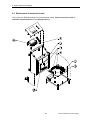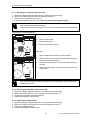
1
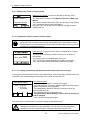
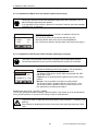
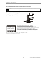
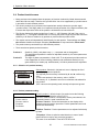
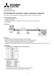
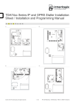
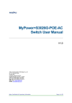
Operating Instructions
GENIUS Control Unit
9 - 18812 96th Avenue
Surrey, BC Canada, V4N 3R1
Tel: (001) 604 607-6028 Fax: (001) 604 607-6026
e-mail: [email protected]
1
TecTronix-GENIUS-BA-CU-EN-3006.doc
Customer Name:
Location:
Date in Service d/m/y:
We would like to take this opportunity to thank you for purchasing your
Metal Detector from TecTronix. The confidence you have placed in our product
is sincerely appreciated and we will endeavour to provide the best service and
support possible.
Please take the time to read the User Manual completely as this provides
you with the expertise necessary to install and adjust the system according to
your requirements. In addition to this, you will learn about the sophisticated
options provided by the Genius electronics.
If you have any problems in the set up and operation of your system, the
TecTronix team are available to assist you.
TecTronix Systems inc.
26688 56th Avenue
Langley, British Columbia
Canada, V4W 3X5
Telephone: (001) 604 607-6028
Fax: (001) 604 607-6026
E-mail: [email protected]
2
TecTronix-GENIUS-BA-CU-EN-3006.doc
Installation Do´s and Don´ts
Electrical
- Do Not cut the connector or the power cables
These cables are equipped with special double shields and connectors and must not be cut. If you require
longer or shorter cables please order them from our parts department. The electrical cables are approximately 10 feet (3m) in length and the connector cables are 26 feet (8m). It is therefore recommended that
consideration be given to where the connection boxes are located and that all cables be installed in conduit.
- Do Not weld in reasonable proximity to the metal detector
Welding in the vicinity of the metal detector will trigger faults.
- Run a clean, constant voltage power supply from the main to the control panel
Voltage fluctuations can cause false tripping therefore a constant voltage transformer is highly recommended.
- Do Not install the metal detector near MCC's or control panels
Stray fields can trigger faults
- Run the connector cables to the metal detector separately
Connector cables are part of the metal detector and have to be protected against noise. It is highly recommended to run them in a dedicated conduit. Both cables can be run in the same conduit. The conduit should
be metal but, must be grounded. If the conduit is to be connected at the transmit/receive boxes on the coil
and/or the control panel, all fittings must be plastic.
- Do Not install the detection coil inside an electromagnetic field (strong power supply fluctuations)
Interferences can trigger faults. For example; Where units are installed in close proximity to chipper motors,
when under high amperage draw, can cause nuisance or false tripping and this may require the fabrication of
a shield.
- Do Not disconnect the metal detector from the power supply main
A constant, uninterrupted power supply enables more sensitive adjustments. Powering the unit on and off
causes it to recalibrate during which time metal will not be detected.
- When welding, do not use the control panel mounting surface as a ground
Mechanical
- Do Not use conductive (Anti-Static) belt material
Non-conductive belt material is preferred. When splicing belts, use a "Finger over Finger" splice for best
results. Ensure all surfaces are clean and free of debris at the splice.
- Vibration less installation of the detector coil (except "VT")
Higher sensitivities can be attained and maintained if the operating conditions are optimal. Ensure the coil is
mounted to a structure that is stationery at all times.
- Eliminate loose metal to metal connections near or within the detection field
Intermittent metal to metal contacts from such things as roller axis, loose bolted connections, or broken welds
can cause the metal detector to false trip especially on the higher sensitivity settings.
- Vibration less installation of the Control Panel
Mount the control panel on a vibration free surface. Vibration can cause premature electronic component
failure.
- Avoid cable whiplash……….
On "VT" Vibratory Conveyor installations, use the supplied cable clamps and tie wraps to secure the cables
to the metal detector housing. Doing so will avoid whip lash at the transmit/receive box strain relief connections. In addition to this we recommend that you loop the cables as they exit the conduit. These loops will
then flex as the conveyor cycles. It is also advisable to follow this procedure on belt conveyor installations.
- Do Not touch the sensor/coil surface of the detector
Mechanical contacts may cause detection errors. Keep the sensing surface free of debris.
- Mount the FLAT PLATE type coils as close as possible to the underside of the vibrating conveyor or
belt conveyor
The closer the coil to the product being conveyed, the greater the sensitivity. Do not allow material to build up
on the sensing face so that it touches the conveyor pan. Doing so creates a closed conductive loop and the
metal detector will false trip.
- Isolate rollers on belt and driven roll conveyors
On belt and roller conveyor applications where a roller is less than 24" (610mm) from the centerline of the
detector, the roller must be isolated on one side to avoid the possible effect of errant static charges. Use a
UHMW shim beneath the bearing and nylon washers or some other non conductive material beneath the bolt
head and nut/flat washer. The bolts should also be sleeved with a non conductive material. It may be necessary to isolate more than one roller in either direction to achieve the desired results.
3
TecTronix-GENIUS-BA-CU-EN-3006.doc
Contents
Contents
1
2
3
General information
6
1.1
1.2
1.3
1.4
6
6
6
6
Technical data
7
2.1
2.2
7
8
5
6
Performance data
Dimensions
Design and method of operation
3.1
3.2
4
Reasons for using the Control Unit GENIUS
Symbols used
Legal basis
Overall view
9
Functional principle
Functional and control elements
3.2.1 GENIUS - Housing
3.2.2 GENIUS - Controller board STE
3.2.3 GENIUS - Evaluation electronics board AWE
9
10
10
11
12
Safety
13
4.1
4.2
4.3
4.4
4.5
4.6
4.7
4.8
13
13
13
13
13
13
13
13
Use to the intended purpose
Notification of risk
Risks in case of non-observance of the safety notes
Safety notes for the operator
Safety notes for operation and maintenance
Notes on residual risk
Consequences of unauthorized modification
Inadmissible operation
Commissioning
14
5.1
5.2
14
14
14
15
16
17
Mechanical Mounting
Connection of the equipment
5.2.1 Connector assignments on the controller board
5.2.2 Electrical connection
5.2.3 Electrical Performance
5.2.4 Electrical Connection of the equipment
Operation / Menu structure
19
6.1
19
19
19
20
21
21
22
22
22
23
23
23
23
24
24
24
25
25
26
6.2
6.3
Quick start
6.1.1 Setting of the most important parameters
6.1.2 Teach-in procedure for new product
Operating mask and Adjustment menu
Set up menu
6.3.1 Check of detector adjustment and software version
6.3.2 Event recording by the GENIUS Log book
6.3.3 Activation of Access Codes
6.3.4 Time setting
6.3.5 Date setting
6.3.6 Language setting
6.3.7 Serial Interface configuration (option)
6.3.8 Setting of Device and Line name
6.3.9 Setting of the unit for conveying speed
6.3.10 Adjustment of the Air pressure monitor (option)
6.3.11 Conveying speed setting with distance measurement (option belt conveyor)
6.3.12 Adjustment of Reject and Level monitor (option belt conveyor)
6.3.13 Adjustment of the Diverter position monitor (option pipe conveyor)
6.3.14 Adjustment of the Diverter Controller (option pipe conveyor)
4
TecTronix-GENIUS-BA-CU-EN-3006.doc
Contents
6.4
6.5
7
8
27
27
27
28
29
30
30
31
31
34
34
The use of the GENIUS metal detector for quality insurance
35
7.1
7.2
35
35
Instruction for setting the performance test intervals
Carrying out a performance validation
Errors and error remedying
36
8.1
36
36
36
36
36
36
37
37
37
37
37
38
39
40
40
40
8.2
8.3
9
Product teach-in menu
6.4.1 Selection of a product memory
6.4.2 Product parameter setting
6.4.2.1 Conveying speed
6.4.2.2 Automatic product teach-in
6.4.2.3 Manual setting of product parameters
6.4.2.4 Options for product effect equalization
6.4.2.5 Input / change of product name
6.4.2.6 Setting of the outputs
6.4.2.7 Activation of performance validation and scheduled testing
Menu Product change
Error messages
8.1.1 Interface to evaluation unit interrupted
8.1.2 Transmitter or receiver faulty
8.1.3 Receiver voltage too high
8.1.4 Battery voltage too low
8.1.5 24V switching output overload
8.1.6 Datememory not existing
8.1.7 Compressed Air
8.1.8 Not rejected
8.1.9 Reject box full
8.1.10 Diverter Position
Undefinable activation of the switching outputs
Replacement of electronic boards
8.3.1 Replacing the control electronics board
8.3.2 Replacing the evaluation electronics board
8.3.3 Replacing the display board
Spare parts, service
41
9.1
9.2
9.3
9.4
41
41
41
42
Spare parts view
Spare parts list
Accessories
Service address
10
Shipping, transport, storing, preservation
43
11
Index
44
5
TecTronix-GENIUS-BA-CU-EN-3006.doc
1. General information
1 General information
1.1 Reasons for using the Control Unit GENIUS
•
•
•
•
Product liability
ISO 9000
TQM (Total Quality Management)
Protection of consumers and of machines
1.2 Symbols used
= Important notes
= Danger notes
= Safety notes
1.3 Legal basis
This equipment complies
• with EMC guideline 89/336/EC and 92/31/EC
• low-voltage guideline 73/23/EC
1.4 Overall view
6
TecTronix-GENIUS-BA-CU-EN-3006.doc
2. Technical data
2 Technical data
2.1 Performance data
Type:
Control Unit GENIUS
Housing:
Sheet metal, painted, pure-orange (RAL 2004) or
FDA white, food grade (RAL 9010) or
stainless steel, glass lead blasted or polished.
Dimensions:
see page 6
Weight:
6 kg
Connecting cable:
(to the detection coil) standard up to 5m (up to 50 m max.)
Mains cable:
1,8 m with plug
Ambient temperature: on request
Type of protection:
IP 65
Operating voltage:
230V / 115V (+10%, -15%), selectable, 50Hz / 60Hz
Current input:
approx. 120 mA
Fuse:
630 mA, slow-blowing
Switching inputs:
2 switching inputs for initiators
1 switching input for light barrier
1 switching input RESET
8 switching inputs for special functions and options
Switching outputs:
1 switching output 24V DC, 200mA for metal detection
2 relay switching outputs for metal detection
1 relay switching output error message
Interface:
Serial interface RS232 or. RS485 (option)
Operation:
Graphic display with 4-key operation
Conveying speed:
depends on type and size of the detection coil used
Can be combined:
Detection coils of GLS, GLS-R, DLS and ELS
Subject to changes due to technical innovation!
7
TecTronix-GENIUS-BA-CU-EN-3006.doc
2. Technical data
2.2 Dimensions
240 mm
315 mm
240 mm
260 mm
145 mm
8
TecTronix-GENIUS-BA-CU-EN-3006.doc
3. Design and method of operation
3 Design and method of operation
3.1 Functional principle
Detector coil
Evaluation electronic
Data
Receive
r
Analog / Digital
Converter
Transmitte
r
Data
Digital
Signalprocessing
Signal ampl.
Receive
r
Quartz oscillator
Serial
Interface
Controller
Printer
Data
LCD-Display
key pad
Relay,24VDC output
Ausgang
24VDC input
Eingänge
Power supply
Microcontroller
Serial
Interface
RS232 / RS485
Memory
1000 events
100 products
PC
SPS
A metal impurity within the aperture of the detector causes an unbalanced condition of the high frequency electromagnetic field, which is recognized by the evaluation electronics.
The product to be inspected can also cause an unbalanced condition. The evaluation electronics is
able to neutralize and store this effect and detect despite of that metal impurities within that product.
The controller acts as the central processing unit and controls the evaluation electronics, display unit,
serial interface for external control units (SPS, PC) and printers. The PC can run also the Data Management System INSIGHT GENIUS.
9
TecTronix-GENIUS-BA-CU-EN-3006.doc
3. Design and method of operation
3.2 Functional and control elements
3.2.1 GENIUS - Housing
Display and key pad:
1
GENIUS
METAL DETECTOR
operation
opération
funcionamiento
3
fault
défalt
error
Reset
metal
4
métal
metal
F1
F2
F3
5
6
F4
(1) LCD display
(2) Function keys F1 - F4
(3) „Operation lamp“: lights
up when mains supply is
ON
(4) „Fault“ lamp: blinks in
case of fault or error
(5) „Metal“ lamp: lights up in
case of metal detection
(6) Resetting of the metal
and alarm
2
At the bottom of the housing:
(7) Cable gland for the mains cable
(8) Cable gland for free use
(9) Cable gland for free use
(10) „Receiver“ cable gland for connecting the detector
coil
(11) „Transmitter“ cable gland for connecting the detector
coil
(12) Cable gland for free use
(13) Cable gland for free use (or connection of the serial
interface (option)
7
8
9
10
11
12
13
10
TecTronix-GENIUS-BA-CU-EN-3006.doc
3. Design and method of operation
3.2.2 GENIUS - Controller board STE
1
2
3
4
6b
6a
5
10 10
7b
7a
14
8
12
13
11
15
16
9
red
Connectors:
(1)
(2)
(3)
(4)
(5)
(6)
(7)
(8)
(9)
„Mains“:
Mains supply
„Fault“:
Potential-free change-over contact
„Metal 1“:
Potential-free change-over contact
„Metal 2“:
Potential-free change-over contact
„24V Output“:
24V switching output
a) 24 Inputs and outputs.
b) Connection detection coil/sensor electr.
a) 24 Inputs
b) Serial interface RS485/RS232
Ribbon cable connector for control panel
Ribbon cable connector Option
Elements connected to mains voltage:
( 1) „Mains“ connector
(10) Mains fuse
(11) Mains voltage selector switch
Elements connected to external
voltage:
(2)
(3)
(4)
Memory devices:
(14) Data battery for Logbook
(15) Program memory
(16) Device and product data memory
„Fault“ connector
„Metal“ connector
„Metal“ connector
11
TecTronix-GENIUS-BA-CU-EN-3006.doc
3. Design and method of operation
12
TecTronix-GENIUS-BA-CU-EN-3006.doc
3. Design and method of operation
3.2.3 GENIUS - Evaluation electronics board AWE
9
8
+9V
xx
GND
GND
+22V
- 22V
- 30V
+30V
GND
7
2
T
-15
+15
R
1
GND
5
3
Connectors:
(1)
(2)
(3)
(4)
(5)
STE RS485:
Power Supply:
Transmitter:
Cable Check:
Receiver:
Test points:
GND
(6) Transmitter
(7) Receiver
(8) Metal signal
(9) Metal signal
13
6
Interface RS485 to the controller board
Power supply from the controller board
Output signal to the detector coil
Control signal to the detector coil
Input signal from the receiver
Common ground for all signals
Sine wave signal (45..50Vss) feeding the
transmitter coil
Sine wave signal from the receiver coils
branch S
branch A
TecTronix-GENIUS-BA-CU-EN-3006.doc
4. Safety
4 Safety
4.1 Use to the intended purpose
The equipment is intended to be used in the following fields of application only in
combination with a corresponding detector coil: SF-DF, free-fall applications, and
conveyor belt applications.
4.2 Notification of risk
People with cardiac pacemaker should not stay in the area of the detection coil
permanently.
4.3 Risks in case of non-observance of the safety notes
There are no known risks or side effects emanating from the electronic unit, if the
equipment is not used to the intended purpose.
4.4 Safety notes for the operator
If potentially explosive materials are examined, the pertinent regulations have to
be observed.
4.5 Safety notes for operation and maintenance
During operation the covers for the electronic unit and/or electronic controllers
must always be kept closed.
For maintenance work at the electric/electronic unit or at the pneumatic unit the
power supply and external circuits and compressed air must always be disconnected.
Maintenance work may only be performed by qualified personnel.
4.6 Notes on residual risk
Disconnect external control circuits.
4.7 Consequences of unauthorized modification
In case of unauthorized modification or repair work all the declarations and guarantees given by the manufacturer will become void.
4.8 Inadmissible operation
Operation out of the specifications given in the technical data.
Operation under high mechanical static and dynamic loads (e.g. heavy system
parts or strong vibrations).
14
TecTronix-GENIUS-BA-CU-EN-3006.doc
5. Commissioning
5 Commissioning
5.1 Mechanical Mounting
• Ensure stable and non-vibrating installation!
• Do not install the detection coil and the electronic unit in the vicinity of interference fields (large
electric motors and frequency converters!) The distance depends on the power consumption of the
motor or of the frequency converter (value for orientation: 5 m).
• Never install the electronic unit in other switchgear cabinets, because this may lead to interference
effects.(e.g. from contactor controls)!
• Cable lengths may only be modified after consultation with „TecTronix Systems“. Use only original
cables. Lay the connecting cable in fixed installation apart from other cables (e.g. fix it with nailing
clips or lay it in a cable duct).
• If several metal detector systems are used, the distance of the detection coils must not be less
than 2m, if these coils stand side by side. If the coils are arranged opposite to each other, the distance must not be less than 10 m. These values apply to large systems; for smaller systems the
distances may be reduced to 50 cm. If, for reasons of space, these distances cannot be observed,
please contact TecTronix Systems service!
5.2 Connection of the equipment
Cable
Shield
In order to meet CSP, UL and CE standards all cable outside of
the housing have to be shielded. The shields must be grounded
immediately after the cable gland.
Housing
The terminals „Mains“ and „Evaluation Unit“ are already factory reconnected.
According to the delivered option several connectors may be used.
5.2.1 Connector assignments on the controller board
10 9 8 7 6
5
4 3 2 1
Evaluation Unit
LF LB LM
PE Outputs
PE N L1
22 21 24
12 11 14
32 31 34
Mains
Fault
Metal 2
Metal 1
24VIN1IN2 LSRST
Inputs
Dt Ck
b a
Tex_B
RS485
TxD RxD
RS232
i7 i6 i5 i4 i3 i2 i1 i0
Inputs
0 1
24V Output
15
TecTronix-GENIUS-BA-CU-EN-3006.doc
5. Commissioning
5.2.2 Electrical connection
Signal
„Fault “
“Metal 1“
Connection
Potential-free relay
contact
Potential-free relay
contact
„Metal 2“
Potential-free relay
contact
„24V Output”
24VDC switching
output
Function
Normal operation:
Contact 21 and 24 closed
In case of a fault:
Contact 21 and 22 closed
Normal operation:
Contact 31 and 32 closed
In case of metal detection:
Contact 31 and 34 closed
Special functions at mode Rapid (for Alarm devices) and
CONSENSE-D (Belt conv. Start/Stop)
Normal operation:
Contact 11 and 12 closed
In case of metal detection:
Contact 11 and 14 closed
Low-activ = yes (see 6.4.2.6):
Normal operation:
In case of metal detection:
Low-activ = no (see 6.4.2.6):
Normal operation:
In case of metal detection:
0V DC to ⊥
24V DC to ⊥
24V DC to ⊥
0V DC to ⊥
Special functions for bidirectinal pusher and for diverter
controller (Option)
Power supply for proximity switches and light barriers
Ground reference for the inputs IN1, IN2, LS and RST
„⊥
⊥“
Ground (GND)
„Outputs“
24VDC switching
outputs wired to
+24VDC
LM:
LB:
„24V“
24VDC Power
supply
LF:
Fault lamp
lights in case of errors
Power supply for light barriers and proximity switches
Signal reference for outputs LF, LB and LM
Signal reference for inputs i0 .. i7
„Inputs“
24V switching inputs IN1
to ⊥
IN2
chapter 7.2)
LS
RST
wired to +24VDC
Inputs to 24V
PE N L1
Ma ins
22 21 24
Fault
12 11 14
Metal 2
Metal lamp
lights on metal detection
Operation lamp lights on test request (see also
1. Proximity switch input for distance measurement /
diverter flap (NPN)
2. Proximity switch input for distance measurement /
diverter flap (NPN)
Start Autotest (see chapter 6.4.2.7)
External Reset input
I0
I1
I2
I5
I7
identically to IN1 but PNP
identically to IN2 but PNP
Pressure monitor
identically to LS but PNP
Free fall mode (Rapid XXXX): connection ot test push
button to activate the diverter unit.
I3,I4,I6, for special applications.
32 31 34
Metal 1 24V Output.
LF LB LM
Outputs
24VIN1IN 2 LSR ST i7 i6 i5 i4 i3 i2 i1 i0
Inputs
Inputs
24V
16
24V
24V
24V
TecTronix-GENIUS-BA-CU-EN-3006.doc
5. Commissioning
5.2.3 Electrical Performance
Potential-free relay contact
250VAC/ 3A
120VDC/ 3A
24VDC outputs
Max current load: 300mA
Inputs: In1 / In2 / LS / RST
Connection of make contacts
against ⊥, resp. NPN outputs
Inputs: i0 .. i7
Connection of make contacts
against+24 V, resp. PNP outputs
17
TecTronix-GENIUS-BA-CU-EN-3006.doc
5. Commissioning
5.2.4 Electrical Connection of the equipment
Only qualified persons are authorized for the following procedure!
Before opening the housing make sure that no mains voltage or any external voltage is
connected!
1.
After unloosing 4 screws fold the cover downward.
Do the wiring according to your needs.
Check the mains voltage selector switch for
correct position.
4. Connect mains power supply.
4.1. The power cord and skintop gland may not be
removed - it is a essential part of the EMCconcept. If the mains plug cannot be used a
conduit box should be used.
11
5
2.
3.
230
11
5
230
3
Mains supply by using the
outlet
Mains supply using alternatively a mains connection box
1
Controller board GENIUS
2
4.2. If necessary, connect plug ST1 "Mains"
Mains cable
Control unit
1
Mains
bl
bn
Yel/gr
Strip of vanish for
cable gland
5
Shield
4
2
3
Cable gland
Skintop PG9
GNLM 3G 0,75
Cable
Plug / connection cable
Shield
Shield
PE
Conductor
Conductor L (brown, bn)
L
PVC - insulation
Conductor N (blue, bl)
N
Shield
Conductor PE (yellow, yel / green, gr)
PE
Sheath
5.
After 5 sec the unit is ready for work
18
TecTronix-GENIUS-BA-CU-EN-3006.doc
6. Operation / Menu structure
O perating m ask
Setting m enu
Cha nge pro duct
Select product
Teach in prod uct
Select product
Teach in product 1
Auto. te ach in
C onvey p ro du ct
C onve ya nce spee d
Freq ue ncy
Prod.co mp.activate d, Sta te : #
Pro duct e ffect too high
M anu . teach in
C onve ya nce spee d
O ptions
Me nu option s
H and setting
N ext
Teach in product 2
Produ ct name
Freefall
O utput adjust
C han ge prod uct name
R eje ct duration
R eset-mode auto / manu
Auto . R eset
M anu . Re set
H and adju stment / Auto .
Automa tic tim e
m easureme nt
Con vey me tal p ie ce ...
repe at
previo us me nu
fin e ad ju stmen t
C onfig uratio n
Fine a djustment
Ha nd adju stment
Setting by ha nd
C onfigu ra tion
Previou s m en u
Testin tervall
C ontrolintervall
Every hou r
Every day
e nter alarm time
Every wee k
e nter alarm time
ID n o. test piece
no alarm
O pe ra ting ma sk
Setup
Setup page 1
D evice da ta
R eceiver adjustme nt / so ftware
Lo gbo ok
G EN IUS L ogb ook
C ode
setting
C ode chan ge Prod.
C lo ck
Se tting clock
D atum
Se tting d ate
La ngu age
L ang uage
Print pro toco l
Cod e te ach in Pro d.
Co de Se tup
Setup page 2
In terface
Interfa ce
D evice na me
D evice name
Line n am e
L ine na me
O ptions
O p tions
Serial setup
Operating mask
19
TecTronix-GENIUS-BA-CU-EN-3006.doc
6. Operation / Menu structure
6 Operation / Menu structure
This section starts with a short form instruction for the most important settings including cross references for the comprehensive instructions.
Afterward all menus are described. To ease the handling the menu structure can be fold out.
6.1 Quick start
6.1.1 Setting of the most important parameters
Language (if necessary):
1. The operation mask appears after power on (see 6.2).
2. Press F1 „Adjustments“ followed by F3 „Setup“ .
3. Press five times key ↓ until „Language“ is marked and press „O.K.“.
4. Select language and confirm with „O.K.“ (see 6.3.6)
5. Return by pressing key „END“ .
6.1.2 Teach-in procedure for new product
1. Press F1 „Adjustments“ followed by F2 „Product teach-in“.
2. If a list of preprogrammed products is displayed press key ↓ until „**NEW**“ appears and confirm
with „O.K.“ (see 6.4.1)
3. Set the conveying speed of the product or speed of belt conveyor and confirm with „O.K.“.
4. Follow the instruction on the display. Pay also attention to the
-window described in chapter
6.4.2.2!
5. Press F4 (“continue”), then F2 (“output adjust”) in menu „Product teach-in“.
6. Select F1 or F2 for automatic or manual Reset of the metal outputs (see 6.4.2.6).
7. Press F1 „Manual Adjustment“ and set the requested „Delay time“ after metal detection and activation of the outputs.
8. Confirm the inputs by pressing key „O.K.“, then press F4 to get to the previous menu.
9. To get to the „Operating mask“ press F4.
10. The GENIUS is now adapted to the surrounded conditions and the product.
11. Check the proper operation by putting a metal particle through the detector and watch if it works
correctly.
20
TecTronix-GENIUS-BA-CU-EN-3006.doc
6. Operation / Menu structure
6.2 Operating mask and Adjustment menu
Product: Product 1
Em: 100% PW: 90,0°
Frq: 794 kHz
F1 adjustments
Product: Product 1
* 20.11.2000 18:52:29 *
** Metal
409
**
F1 adjustments
20.11.2000
F1
F2
F3
F4
18:59:16
change product
teach in product
setup
operating mask
Operating mask: is displayed during operation.
Only this mask shows „metal detection“ and „self monitoring“
Displayed information:
Name of current product
Em: Sensitivity
PW: Product angle
Frq: Frequency
„DETECT“ appears when metal is detected. It disappears after 1
second. If a reject unit is controlled it will be extinguished with
the signal of the light barrier that synchronizes the rejection.
If activated, “QUICKLEARN” is blinking (see 6.4.2.4).
The analogue metal signal is displayed as a bar graph.
Key F1 gets to Adjustment menu.
Metal mask: This mask appears after metal detection and after
the set delay time (see 6.4.2.6) . At the same time the metal
outputs are activated. After the ON- time or manual RESET the
operation mask appears.
This mask is only active in the operation mode. If during
operation a different menu was selected the metal outputs
are set despite of it.
Displayed informations:
Date and time of detection
Amplitude of the metal signal
(max. 2000)
Setting menu: Pressing of the keys F1, F2 or F3 get to the
menus, where products can be changed, new products taught in
or device parameters can be set (Set up).
When the Access code was activated (see 6.3.3), the appropriate code must be input in advance. If the access code was
wrong, the display skips to the operating mask.
Key F4 get immediately to the operating mask
Exception: If no product is programmed the line F1„ change
product“ is suppressed.
Additional information:
Date and time
21
TecTronix-GENIUS-BA-CU-EN-3006.doc
6. Operation / Menu structure
6.3 Set up menu
The Set up menu allows to set all product independent parameters, i.e. conveying speed, access
codes, clock, language...
device data
data logger
code setting
clock
date
language
END O.K.
Setup page1: the selection of „Setup“ in adjustment menu gets to the
first page of the adjustment menu.
The requested parameter is selected by ▼ and ▲ followed by „O.K.“ .
Return to operating mask press key „END“.
interface
divice/line
Units
Compressed air
Reject/Level
Setup page 2: the second page is activated if the page cursor is on the
bottom line and key ▼ is pressed.
Select parameter as described above.
The function requested is selected with the ▼ ▲ keys and „O.K.“. The
functions „Compressed air“ and „Reject/Level“ are active if option
was factory set. (see 6.3.10, 6.3.11, 6.3.12, 6.3.13 and 6.3.14).
END O.K.
6.3.1 Check of detector adjustment and software version
Receiver adj.
1,65V
794kHz 0%
Software:
STE: V#.## AWE: V#.##
Board Nr: #
O.K.
Receiver adj. - 1%....1%
1,65V
794kHz 0%
Software:
STE: V#.## AWE: V#.##
-
+
Receiver adjustm./software: Select „device parameters“ in Setup
menu
page 1. No settings are possible in this menu.
Displayed informations:
Adjustm:
Receiver voltage (Vpp)
Frequency (kHz)
Frequency deviation in %
Software:
STE: Software version of controller
AWE: Software version of evaluation electr.
Board Nr.:
printed circuit board no. of the contoller.
Return to Setup page 1 press „O.K.“
To change the frequency deviation within the limits press the O.K. for
more than 2 seconds.
It will be necessary if two detectors are close together so that they will
affect each other.
The keys „-„ and „+“ will change the frequency stepwise. O.K. gets to
Setup mode page 1
O.K.
22
TecTronix-GENIUS-BA-CU-EN-3006.doc
6. Operation / Menu structure
6.3.2 Event recording by the GENIUS Log book
GENIUS logbook
20.11.
19:44:45
change product
PRODUCT 1 > PRODUCT 2
PRNT
O.K.
GENIUS Log book: Select „Log book“ in Setup menu page 1. The last
1000 events are stored in a database and can be displayed. The latest
event is displayed first.
Displayed information:
Date and time of the event
Kind of event:
• Metal:
Intensity, number of metal detection since
commissioning
• Fault:
Number of faults since commissioning,
Type of error
• Message: Power on /off
• Product change
old product → new product.
• Batch change
• Product parameter changed
The keys ▼ and ▲ allow scrolling the event memory.
If the option „serial interface“ has been set, the key „PRNT“ will print
out the logbook. (See operational manual Control Unit GENIUS option
serial interface)
6.3.3 Activation of Access Codes
Code Prod. Change / Code Prod. teach-in / Code Setup: This menu
is selected by choosing „Code“ in Setup menu page 1.
This menu allows to enter the access codes for „Change product“,
„Teach-in Product“ and/or „Setup“.
The - and + enter the figures 0...9, the key → selects the digit.
-
+
->
O.K.
The input is completed by pressing „O.K.“
The input masks for the 3 different access codes are recalled one
after
the other automatically before getting the Setup page 1mask.
If all of the access codes are in use, the following hierarchy is given
Setup
Setup code:
yes
Product teach-in code: no
Product change code: no
Product teach-in
yes
yes
no
Product change
yes
yes
yes
6.3.4 Time setting
->19:59<-
+
Setting of time: Select in Setup menu page 1 „time“.
With F3 Hour or Minute is selectable. The keys + / - are used to set
the time.
Complete the input with „O.K.“
hour O.K.
23
TecTronix-GENIUS-BA-CU-EN-3006.doc
6. Operation / Menu structure
6.3.5 Date setting
->mo,20.11.2000<-
-
+
day
Setting of Date: Select in Setup menu page 1 „date“.
With F3 Day, Month or Year is selectable. The keys +/- are used to
set the date.
Complete the input with „O.K.“
Pressing „O.K.“ returns to Setup menu page 1.
O.K.
6.3.6 Language setting
deutsch
italiano
english
svenska
francais
dansk
nederlands
ESC O.K.
Language: The language is set by selecting in menu Setup page 1
„Sprache“. Use ▼ and ▲ to choose one of the 7 available languages.
„O.K.“ completes the selection and returns to Setup menu page 1
displayed already in the chosen language.
„ESC“ returns to Setup menu page 1 without changing the preset
language.
Available languages (included in the standard software package):
deutsch
German
english
English
francais
French
nederlands
Dutch
italiano
Italian
svenska
Swedish
dansk
Danish
6.3.7 Serial Interface configuration (option)
This menu is only activated if Genius is equipped with a serial interface!
Interface: See operational manual „Control Unit GENIUS serial interface“.
interface
none
printer online
printer portable
PC/SPS
ESC O.K.
6.3.8 Setting of Device and Line name
Device name / Line name: See
op. manual „Control Unit GENIUS
serial interface“.
The input names will only appear
on the print outs of a connected
event printer.
enter line name:
enter divece name:
LINIE
DETECTOR 1
1
= 012...ABC...
= 012...ABC...
O.K.
O.K.
24
TecTronix-GENIUS-BA-CU-EN-3006.doc
6. Operation / Menu structure
6.3.9 Setting of the unit for conveying speed
Speed is shown in
Meters per Second
SEL
ESC O.K.
Measuring unit Speed: this menu is selected by selecting „units“
In Setup menu page 2.
This menu allows to choose either Meters per Second or Meters per
Minute.
The units are selected with the key „SEL“ and the input is confirmed by
„O.K.“ which also skips to Setup mode page 2.
Using the „ESC“ key will also return to Setup mode page 2 without
changing the unit.
6.3.10 Adjustment of the Air pressure monitor (option)
This menu is activated if Genius is equipped with an air pressure indicator!
During reject the air pressure can fall under the adjusted limits of the pressure indicator.
The air pressure is not monitored during and a certain time after reject (recovery time) as
it can be out of limits during this time.
Recovery time: To get to the menu select „Compressed air“ in Setup
menu page 2.
Recovery time
The keys – and + set the air pressure recovery time in steps of 5
0 ms
milliseconds.
Set 0 ms to disable.
0 msThe
eingebe
n monitor is disabled when set to 0 ms.
pressure
„O.K.“ confirms the setting and gets back to Setup menu page 2.
„ESC“ returns also to Setup menu page 2 without any change.
+ ESC O.K.
6.3.11 Conveying speed setting with distance measurement (option belt conveyor)
If the system is delivered with the option “path measurement”, then two proximity switches have to be
connected to the corresponding input terminals of the control unit (see also 5.2)
conveyance speed
0.03 .. . 0.40 m/s
v: 0.30 m/s
100 mm/clk
-
+
O.K.
Conveyance speed:
Select „Conveyance speed “ in Setup menu page 2.
The pulse frequency of proximity switches triggered by a belt roller is
used to calculate the conveying speed.
The corresponding distance of the belt in mm/pulse (clk) of the
proximity has to be set.
The calculated speed v is displayed in m/s.
This parameter is already factory preset on delivery and should
not be changed!
„O.K.“ returns to Setup menu page 2.
This option does not use the menu Conveyance speed as described in 6.4.2.1
Attention!
The optimum performance is only guaranteed, if the set value for conveying speed
corresponds with the real product speed. Deviations should be less than 20%!
25
TecTronix-GENIUS-BA-CU-EN-3006.doc
6. Operation / Menu structure
6.3.12 Adjustment of Reject and Level monitor (option belt conveyor)
This menu is only activated if a light barrier is installed at the reject box!
During reject the product must have passed the light barrier after 3 seconds. If not, an
alarm message is generated „Not rejected“.
If the light barrier is activated by a product for more than 5 seconds, the alarm message
„Reject box full“ is displayed.
Reject Monitor
-> Reject :
Level :
nein
ja
Reject/Level monitoring: This menu is selected in Setup „Reject/Level“ on page 2.
The monitoring mode can be selected with the key „SEL“.
With keys ▼ and ▲ the mode can be activated/disabled.
O.K. confirms the selection and gets back to the Setup menu page 2.
SEL O.K.
6.3.13 Adjustment of the Diverter position monitor (option pipe conveyor)
This menu is only activated if the diverter is equipped with the appropriate sensors!
Two different times have to be set, as the forward and the reverse time is different.
Forward:
Reverse:
0ms
: 0ms
To disable set to 0 ms
-
+
SEL O.K.
Adjustment/ Enabling of the Diverter Monitor: This is selected in
Setup menu page 2 after selecting „Diverter Monitor“
Two different times have to be set, which are selected with „SEL“
and set with + and –.
Forward: time of the diverter flap to get from the normal to reject
position.
Reverse: time to get back from reject to normal position.
The diverter monitor is enabled if the two values are set > 0 ms.
The diverter monitor is disabled if just one value is set to 0 ms.
O.K. gets back to the Setup menu page 2
Settable time range: 0ms....step 5ms...5000ms.
The monitor generates the alarm message „Diverter position“ if the diverter is not in normal position
during normal operation, or moves not or to slowly in case of metal detection.
If the times were set to short, the monitor will display „Diverter position“.
To get to the menu to adjust the times press RESET button and then F1 (red lamp is still
blinking).
After resetting (or disabling) the diverter monitor the alarm signal (red lamp) have to be
reset.
26
TecTronix-GENIUS-BA-CU-EN-3006.doc
6. Operation / Menu structure
6.3.14 Adjustment of the Diverter Controller (option pipe conveyor)
This menu is activated only if Genius is used in combination with a special diverter unit
for textile fibers (Quick flap)
The magnetic valve which is triggered for
return motion is connected to terminals
„24V Outp.“ pin 1.(see also 5.2.1).
Return time:
0.00 s
To disable enter 0 ms
-
+
Adjustment/ Enabling of the diverter controller:
This menu is selected in Setup menu page 2 „Quip flap
The time duration can be set to control a second magnetic valve
which returns the diverter to normal operation position.
The setting is completed by O.K. and returns to Setup page 2.
„ESC“ returns without changing the setting to Setup page 2.
ESC O.K.
Adjustment range for the return time: 0ms...step 50ms ...1.00s
The setting of 0 ms disables the function.
27
TecTronix-GENIUS-BA-CU-EN-3006.doc
6. Operation / Menu structure
6.4 Product teach-in menu
• Many products to be inspected have the property of electrical conductivity. Metal detectors would
detect this effect as metal. Therefore this „product effect“ has to be suppressed by a product teachin procedure for each different product.
• The electric conductivity of products to be inspected are usually indicated as „product angle“
(=product effect). This angle (which is an important internal parameter of the signal evaluation) has
to be set that way that the effect of the product is eliminated or at least minimum.
• The Genius displays this product angle from 0..step 0.1...180°. Between 180° and 0° the value is
displayed as „---„. The signal evaluation then is not using the product angle and provides maximum
sensitivity to all kinds of metals for dry products or products without product effect.
• The outputs can be set independently and differently for each product. These settings are: Delay
time between detection and output activation, Duration time of output activation, Reset mode.
• The product memory can handle up to 200 different products.
• There are also two preset product memories:
Product A
Product B
Sensitivity (100%), and phase comp. (----) are preset and not changeable.
This parameters represent the maximum adjustable sensitivity. All further parameters
are adjustable.
The angle of phase compensation is fixed to 90°. Th is adjustment provides maximum
noise suppression of the surrounding (vibrations and mechanical shocks) but very
good sensitivity for metals (esp. stainless steel). All further parameters are adjustable.
6.4.1 Selection of a product memory
1:PRODUCT 1
2:PRODUCT 2
3: **NEW**
ESC O.K.
Select product: Selected in „Adjustment“ menu it displays the list of
already preprogrammed products.
The required product memory is selected by ▼ and ▲ confirmed by
„O.K.“
To add a new product to the memory, select „**NEW**“.
The memory no. 0 „Standard“ can not be overwritten and selected for
new product.
„ESC“ returns to the operating mask, already set inputs are ignored.
6.4.2 Product parameter setting
teach in product
F1 auto. teach in
F2 manu. teach in
F3 options
F4 continue
Teach in product 1: After the input of a product name the following
functions can be selected by using F1 to F4:
If in menu „Select Product“ a new product memory was selected, the
„Automatic teach-in“ mode is carried out first.
„F1 Auto. Teach in“: Follow the instructions on the display which
guides through the teach-in procedure. Product parameters are found
out and set automatically.
„F2 Manu. Teach in“: Product parameters can be adjusted individually
by hand.
„F3 Options“: Allows to optimize metal detection in case of small
product effects or step by step conveying operation.
This menu is not activated in Free fall or SF/DF mode.
28
TecTronix-GENIUS-BA-CU-EN-3006.doc
6. Operation / Menu structure
„F4 continue“: gets to next menu (see next page)
teach in product
F1 product name
F2 output adjust
F3 testintervall
F4 operating mask
Teach in product 2:
„F1 Product name“: A 10 character name can be entered.
„F2 Outputs“: The ON/OFF state of the outputs can be programmed
(Eject duration, delay time, reset automatic /manual)
„F3 Testintervall“: A performance validation and scheduled testing
can be activated.
„F4 Operating mask“: Returns to operating mask.
6.4.2.1 Conveying speed
One of the following operating modes is factory preset :
Free fall:
Metal separators of the series Rapid 4000, 5000, 6000
The conveying speed is preset to 3 m/s and cannot be changed.
Belt conveyor appl.
with timer:
Belt conveyors working at constant speed
The conveying speed is set during the teach in procedure of a product.
Belt conveyor appl.
Belt conveyors working with variable speed (option):
with path measurement: The current conveying speed is measured by proximity switches (see 6.3.11).
Therefore the following menu will not appear.
Before each teach-in procedure (manually or automatic) the menu „Belt conveyor time measurement“
and requires to set the conveying speed.
Attention!
The metal detector works at optimum sensitivity if set speed and real conveying speed
are identical!
In order to emphasize the importance of this parameter the controller requires the input
of the conveying speed.
Optimum:
##,## m/s
Range:
##.## m/s ... ##.## m/s
-
+
Conveying speed:
Use + / - to adjust the current speed of the product (or belt speed) in
m/s
The displayed range shows the limits, which the controller is able to
operate properly at highest sensitivity. This limits are device parameters and depends on the geometrical size of the detector head.
O.K.
Pressing „O.K.“ gets to automatic or manual teach in mode.
The shown limits of the conveying speed range are absolute values!
If the conveying speed is set out of this range no detection will be performed!
29
TecTronix-GENIUS-BA-CU-EN-3006.doc
6. Operation / Menu structure
6.4.2.2 Automatic product teach-in
teach in product
Please convey product
several times through the
detector, then push F4.
O.K.
teach in product
Product compensation
activated. Convey
product again for several
times, then push F4.
Status: #
Convey product: After choosing „Auto. learn“ in menu „Teach-in product“
(when „New product“ was selected before, this menu is skipped) and after a
short „Please wait“ message the system requires to convey a product.
Pay attention to the instructions below!
Confirming the action by pressing the key „O.K.“ normally „Product compensation status 2“ is displayed.
With the multi frequency version (option) „Frequency change“ will be displayed. The lower frequency will then be selected.
Prod. Comp. active, Status #: This step sets the product compensation
parameters, which are „phase angle“ and thresholds for the metal alarm.
Confirm after several runs by pushing „O.K.“ This procedure will be required
several times depending on the strength of product effect. The numbers of
steps is displayed as „status“.
If the teach in procedure has been successful then the menu „Manual
parameter setting „ appears, which allows to manually adjust the automatic
set parameters (see also below).
O.K.
Product effect extremely high: This message is displayed if the system was
not able compensate the product effect.
After pushing „O.K.“ the main menu for „Product teach-in“ is activated again
in order to repeat the automatic teach-in procedure. This is caused most
likely during the teach-in procedure by heavy interference or disturbances.
teach in product
Very big Effect!
Please teach in
the product again.
Possible reasons for unsuccessful teach-in procedure:
O.K.
Reason:
Remedy:
Vibration of the detector coil during
teach-in procedure
Metallic contaminants in product
Several trials without success:
Product effect can not be compensated
Repeat teach-in procedure
Ensure that metal-free product is
used for teach-in procedure and
repeat.
Ask TecTronix Systems service for
help. Send test sample of the product.
To get optimum product compensation, which results in optimum sensitivity, pay attention to the
following:
• The real conveying speed must correspond with the rate which was set at Setup (deviation
max. ± 20%).
• During product teach-in procedure the products must be conveyed always in the same direction.
• For products conveyed piece by piece each step must be repeated minimum 2 times. Better
results are achieved with several repetitions to average product straggling.
For products conveyed continuously wait, as a thumb rule, that the product has passed 5 x
of the detector length before confirming and initializing the next step.
• Avoid vibrations during teach- in procedure. Vibrations would considerably affect the results!
30
TecTronix-GENIUS-BA-CU-EN-3006.doc
6. Operation / Menu structure
6.4.2.3 Manual setting of product parameters
sensitivity. 8 .. 17
>se: 94% pa: 168,9°
Frq: 794kHz
-
+
SEL O.K.
Manual parameter setting: select „Man. learn“ in main menu „Product teachin“ for manual setting of the parameters for product effect compensation and
sensitivity The menu appears also after a successful teach in procedure.
Key „SEL“ selects the parameter. The first line of the display shows the name
of the selected parameter and it s adjustable range. The keys / are used
to modify.
The bar graph with integrated trigger threshold displays the metal signal.
Thus the effect of modifications can be seen immediately.
Sensitivity (Sens): The sensitivity can be selected between 1 ...100%. The
trigger threshold is shifted on the display from left to right with descending
order.
Product phase angle (PA): Adjustable from 0,0° to 180,0°.
Between 0,0° and 180,0° „-----“ is displayed. This mean s that product compensation is totally deactivated, which allows to run the evaluation unit at the
highest possible sensitivity for all kinds of metals from the physical point of
view.
Pressing „O.K.“ returns to main menu „Product teach-in“.
Frequency (Frq) (option): with the multi-frequency version the frequency can
be selected.
It has to be considered: the higher the frequency the higher the product effect.
6.4.2.4 Options for product effect equalization
Teach in product
F1 tracking : yes
F2 quicklearn: no
F3 halfwave : no
F4 previous menu
Menu Options: after selecting „Options“ in menu „Product teach in 1“
different signal evaluation modes can be selected by F1 to F3
„F1 Tracking“: Slight drift caused by the product variation is automatically
compensated and also shown on the display.
„F2 Quicklearn“: Considerable changes of products (i.e. changing in consistency) up to 5°, which would cause metal alarms, are dete cted and automatically corrected after 2 detections (products). If there is enough space between
detector and reject unit (three times product length incl. gap) no rejection is
carried out only in case of metal detection.
„F3 halfwave“: Specially used for stop and go conveying systems
Drawback: Increased noise sensitivity.
„F4 Previous menu“: Get to mask „Product teach in 1“
31
TecTronix-GENIUS-BA-CU-EN-3006.doc
6. Operation / Menu structure
6.4.2.5 Input / change of product name
-> PRODUCT
2 <-
, = 0,1,2...ABC...
->
O.K.
Change product name: After selecting a product memory in menu „Select
product“ a 10 character name can be given. If **NEW**“ was selected in the
product selection menu ,the name „PRODUKT #“ is used as a default text.
▼ and ▲ changes the marked character, key → selects the place of the
character.
„O.K.“ completes end returns to „teach in product 2“.
6.4.2.6 Setting of the outputs
This menu allows to set six parameters to determine the state of the outputs.
Parameter
Reset mode:
Range
automatic / manual
Delay
Timer: 50 ms ... 3 min
Distance: up to approx. 10
meters
50 ms ... 2 min
Distance: see above
Yes / No
Eject duration
Metal alarm in
case of Fault
Low-Aktiv
Yes / No
Description / remarks
Determines, if the outputs after activation by a metal signal
are reset automatically or manually by an external signal or
by push button.
Delay time resp. distance between metal detection and
output activation
Duration of output activation.
Not used at reset mode „Manual“.
Sets also the metal alarm output in case of faults (self
monitoring )
Set the high or low active status of the electronic output
Flip-Flop
(only belt conv.)
Yes / No
Determines if the 24V outputs should switch by turns, to
control a pusher rejecting to both sides. (High speed rejecting)
Rel1-Man
(only pipe conv.)
Yes/ No
Determines if relay „Metal 1“ is reset manually (yes) or
automatic (no)
It is possible to program the outputs for each individual product. Normally the same
setting is used at one installation. These parameters are set during teach-in procedure of
the first product. When adding additional products the parameter of the first product are
set as a default setting.
The GENIUS is factory preset to the following operating modes:
Free fall (gravity feed):
For use with metal separators of the series Rapid
4000, 5000, 6000
Belt conveyor with timer application: For use with belt conveyor at constant speed.
Belt conveyor with distance measurement: For use with belt conveyor at variable speed
The outputs are programmable and can be set according to the application:
Output adjust
F1 auto. reset
F2 manual reset
F3 configuration
F4 previous menu
Reset mode auto / man: after selecting„output adjust” in menu „teach in
product 2“:
„F1 Auto. Reset“: Selecting of menu for setting delay time and reject duration time.
„F2 Manual reset“: Selecting the menu for setting the delay time. This menu
will not appear in operation mode ” Free fall”
„F3 Configuration“: Setting of the switching characteristic of outputs.
„F4 Previous menu“: returns to menu „teach in product 2“
32
TecTronix-GENIUS-BA-CU-EN-3006.doc
6. Operation / Menu structure
Free-fall (Rapid device)
hand adjustment
duration
-
x.xx s
+
Duration: After selection of „output“ in menu „product teach-in“ the parameter
„Duration“ can be set.
For metal separator applications this parameter is preset to automatic reset
and delay time „0“.
The + / - keys allows to set the output duration time from 0.2, step 0.05 to 120
seconds.
„O.K.“ confirms the input and returns.
O.K.
Timer setting for belt conveyor application
setting delay
and duration:
F1 setting by hand
F2 automatic time
timemeasurement
hand adjustment
delay time:
duration:
-
##.## s
##.## s
+
delay time:
duration:
O.K.
##.## s
##.## s
convey metal piece
F1 reject activation
F2 repeat
F3 previous menu
F4 fine adjustment
Manual setting / Automatic: Pressing F1 or F2 in “Reset mode auto / man“
gets to the selection menu to input the data for delay or duration time by hand
or to set automatically.
„F1 Setting by hand“: If delay and duration time is known or very short it is
recommended to input the data manually.
„F2 Automatic time measurement“: In case of long delay and duration time
this menu will assist to find out the delay and duration time during system set
up. A piece of metal is passed through the detector and triggers the time
measurement system.
Press the appropriate key when the metal arrives the diverter unit.
Hand adjustment: This menu appears after pressing F1 „Setting by hand“
to set the delay time and duration time of the outputs. Use + / - keys to input
data.
When „Auto reset“ was chosen the keys ▼▲ are used to select delay time or
duration time set.
If one product has been already programmed the parameters set for this
product are used as default parameters.
„O.K.“ returns to „Reset mode auto / man“.
Convey metal piece: When choosing F2 „ Automatic time measurement“ the
value for delay time (and duration time) can be determined by a stop watch
function. The display will change related to the context.
Instruction:
1. The default values are displayed and the operator is requested to convey a
piece of metal through the detector.
2. As soon as the metal is detected the stop watch is triggered to measure
the delay time. When the metal piece arrives the ejector press key F1
„Eject“.
3. The metal outputs are activated and the stop watch is stopped.
If Manual Reset was chosen then the outputs stay activated until anyone
of the keys is pressed.
If Automatic Reset has been chosen then the stop watch starts and runs
again as long as the key F1 is pressed. This action determines the output
duration time. Then the outputs are reset
4. The procedure step 1 to 3 can be repeated by pressing F2.
5. F4 allows fine adjustment by hand.
6. F3 gets to menu „Reset mode Auto / Manu“. The set values are cancelled.
33
TecTronix-GENIUS-BA-CU-EN-3006.doc
6. Operation / Menu structure
fine adjustment
delay time:
duration:
-
##.## s
##.## s
+
Fine adjustment: After Selection of F4 and „Convey metal piece“ the determined values can be adjusted by hand. See also „Hand adjustment“.
„O.K.“ returns to „Product teach-in“ menu.
O.K.
Distance measurment setting for belt conveyor application
The same procedure as 0 „Timer setting for belt conveyor application“ but the input of seconds
changes to millimeters.
The distance between detector head and rejector can be measured by means of a measuring tape and
this value can be set directly (assuming that the parameter mm/ pulse was set correctly in Setup menu
see 6.3.11).
When using a light barrier for synchronization (preset on request) the distance between the light
barrier and the ejector is decisive.
Setting of the outputs
Output adjust
F1 M by Fault:yes
F2 low-aktiv : no
F3 Flip-Flop : no
F4 last menu
Menu configuration: after selecting „configuration“ in menu „Reset auto
/ man“ the outputs can be set as follows:
„F1 M at F“: (Metal alarm in case of Fault) if “yes” is selected then the
metal relay is activated additionally to the fault relay.
„F2 Low-active“: If “yes” is chosen then the output for the magnetic
valve is switched to 0VDC when activated.
Operation mode Belt Conveyor:
„F3 Flip-Flop“: If set to „Yes“ the 24V outputs controls a pusher that
way that the contaminated product is one time rejected to the left and
next time to the right.
Operation mode Pipe Conveyor:
„F3 Rel1-Man“: If set to „Yes“ the relay „Metal 1“ is set. It is reset
when the RESET button is pressed (even if Reset auto has been
programmed).
„F4 Last menu“: returns to menu „Reset Auto / Manu“.
Although the above settings can be done for each single product, but done only for
product they are used automatically for all others. The parameters have to be set for the
first product at the teach-in procedure. If products are added to the product memory, the
above parameters are set automatically as preset parameters.
34
TecTronix-GENIUS-BA-CU-EN-3006.doc
6. Operation / Menu structure
6.4.2.7 Activation of performance validation and scheduled testing
no alarm
every hour
every day
every week
extern
ESC O.K.
SEL
O.K.
Control interval: select „test interval“ in menu “teach in product 2”.
The alarm mode is chosen by using ▼ and ▲ followed by „O.K.“.
Selection of „No alarm“ or pressing key „ESC“ returns to menu “teach
in product 2”.
Selection of „every hour“ causes a self check alarm every hour.
When chosen, the menu „Performance check“ (see below) appears
automatically.
Selection of „every day“ causes a self check routine at a certain
hour of a day.
Automatically the menu to input the requested „Alarm time“ appears
(see above, „Set time“), then the menu „Performance check“ (see
below) appears.
„every week“ is identically to „daily“ but in addition the requested
day of the week have to be programmed.
(For more details see also 7).
„Extern“: the performance check is called, if the input LS is activated (see 5.2.2).
Performance Check: This menu appears automatically, when „Control interval“ was selected. The performance validation is carried out
by putting prepared metallic test pieces through the detector.
For each product up to three different test pieces can be set. If only
one test piece is used set test piece 2 and 3 to 00.
Use key „SEL“ to select test piece 1, 2 or 3 and set the identification
number
(00 .. 99) with ▼ and ▲.
Pressing „O.K.“ get to menu “teach in product 2”.
(For more information see also 7).
6.5 Menu Product change
A:PRODUCT A
B:PRODUCT B
1:PRODUCT 1
ESC O.K.
Select product: after selecting „Product change“ the number of products which were already stored are listed.
Use keys ▼ and ▲ to select a stored product. „O.K.“ confirms the
selection.
„ESC“ returns to operation mask, inputs are ignored.
Note: Pressing „O.K.“ without changing the product number
(i.e. change from product 1 to product 1) is interpreted as new „batch“
which resets the counter for number of metal detections and faults to.
35
TecTronix-GENIUS-BA-CU-EN-3006.doc
7. The use of the GENIUS metal detector for quality insurance
7 The use of the GENIUS metal detector for quality insurance
To meet the requirements of the Total Quality Management and of the HACCP, GENIUS
provides beside the printout capabilities of logged data (see separate operational manual for the serial
interface) a performance interval check system.
7.1 Instruction for setting the performance test intervals
1. Teach-in product
2. Convey product with a metallic test piece, which have to be detected. Mark the metallic test piece
with a number between 1 and 99.
3. If necessary repeat this procedure one or two times, and mark them with numbers. If only one
metallic test piece is used input the number 0 for the second and third.
4. In menu “Control interval (see 6.4.2.7) select „Alarm mode“. The interval is selectable between
hourly, daily and weekly performance check. If daily or weekly check interval has been seleceted,
then the hour has to be programmed, too. If the hourly check has been selected the performance
validation check is requested every full hour.
5. Finally set for the product to be inspected the test piece numbers.
6. If several GENIUS, equipped with the serial interface, are in operation name each device and line
in the Setup that each system can be identified easily. (see 6.3.8 and operational manual Control
Unit GENIUS option serial interface).
7. Use also user identification numbers for the operators to be identified later on the performance
check report.
7.2 Carrying out a performance validation
Audit Check demand!
Enter User-ID:
####
If the system clock is equal to the set time then the green LED („operation“) is blinking, the digital output LB is set to High (see chapter
5.2.2) and the operator is requested to input his user identification
number.
At the same time „test request“ is recorded in the log book data base.
The test is started with „O.K“.
O.K.
audit-check
convey testpiece #
F1 : detected
F2 : not detected
No.#
The operator is requested to convey the numbered test piece and to watch
whether it is detected or not.
The detection is shown on the display for 1 sec „** DETECT **“
Confirm by F1 or F2 (it is also possible to convey the test piece several times
at different areas of the aperture).
Note: The operator is responsible to use the requested and set test
piece.
The metal detector is not verifying the kind of metal piece used for this
procedure.
Three different test pieces (i.e. three different kind of metals) can be used
according to the set test procedure.
All events during the entire test procedure are stored in the event data base.
The test is finished after selection of F1 or F2 and skips to the operating mask
(except mode „Printer portable“ was selected, see below)
The test results can be displayed when selecting the logbook (see operational
manual Control Unit GENIUS option serial interface)
36
TecTronix-GENIUS-BA-CU-EN-3006.doc
8. Errors and error remedying
8 Errors and error remedying
If you should have any questions, please state the equipment type and serial
number!
8.1 Error messages
Error massages are indicated by the red LED „Fault“ located on the panel and the fault relay is released (see 5.2.1). In addition the metal alarm relay of the conventional design is released, too.
8.1.1 Interface to evaluation unit interrupted
This message appears if the data interchange between evaluation board (see spare parts view 9.1
No.4) and controller unit is interrupted.
Possible causes
Data communication cable between evaluation electronics board and control electronics board is broken.
Interface module broken.
Remedy
Check cable and connectors with ohmmeter;
Replace cable, if necessary
Replace evaluation electronics board and control
electronics board
8.1.2 Transmitter or receiver faulty
This message appears, if either the transmitter voltage or the receiver voltage is very low.
Possible causes
Broken transmitter connecting cable
Broken search coil
Remedy
Connector (3) „transmitter“ at the evaluation board
(see 3.2.3), switch off and on. If still failure, replace
evaluation board and/ or transmitter cable.
Check search coil for mechanical damage;
Replace the search coil, if necessary
8.1.3 Receiver voltage too high
This message appears if the RF voltage at the receiver is too high.
Possible causes
Big metal part (e.g. aluminum ladder, screwdriver,
hammer, bracelets) directly beside or in the detection
coil.
Improper installation of the search coil
Remedy
Check the detector head and the surrounding. Sometimes metal parts can be found inside or underneath
the belt.
See Op. Man Detection coil: „Installation
If detector head DLS is used, check on loose centering
pins or fastening bolts.
8.1.4 Battery voltage too low
Possible causes
The buffer battery (see 3.2.2) located on the controller
board is flat.
Remedy
Contact TecTronix Systems service
8.1.5 24V switching output overload
Possible causes
Short circuit at the connection cable to magnetic valve
of the reject unit
Remedy
• Check cable and plug of short circuit with ohmmeter (if necessary replace cable)
• Check the resistance of the magnetic valve, which
is 320...340 Ω ( or 100...140 Ω for pusher application).
37
TecTronix-GENIUS-BA-CU-EN-3006.doc
8. Errors and error remedying
8.1.6 Datememory not existing
Possible causes
Remedy
Appears after POWER ON. The device data memory
Switch off power. Open electronics housing and check,
(see 3.2.2 and 8.3.1) is either not existing or damaged. if the memory device exists and is properly fixed
8.1.7 Compressed Air
Possible causes
Remedy
Appears on display if the air pressure monitor responds or the connection to the sensor is interrupted.
Extend the air pressure recovery time
Check the air pressure. Minimum value 2 bar. Increase, if necessary.
Check the cable to the air pressure monitor. Switch off
Power, open housing. Check with meter at connector
6a (24V) and 7a terminal i2 (see 3.2.2).
With connected compressed air : < 20 Ω
Without compressed air connected: open
If not, replace sensor and/or cable
8.1.8 Not rejected
Possible causes
Remedy
Appears, after rejection, if
no signal was sent by light barrier.
Causes:
Product was not rejected
was not detected by the light barrier
Sensor connecting cable broken
Adjust delay time and reject duration time properly
If the error repeats, check sensor and/or connection
cable
8.1.9 Reject box full
Possible causes
Remedy
Appears, if the light barrier is blocked by products.
Empty the reject box.
A short circuit in the connection cable causes the same If reject box is empty and the error message is not reerror message
settable, check the connection cable
8.1.10 Diverter Position
Possible causes
Remedy
Appears during reject operation of the diverter, if
signal timing is not correct,
diverter is broken
diverter too slow
Fix the diverter mechanics
Check diverter if tight or wedged pieces
Check air pressure (min. 5 bars)
Caution! Danger of accident!
Disconnect air supply!
Forward and return time set too short (see 6.3.13)
Connection to the sensors defective
Prolong the time settings
Check cable and sensors
38
TecTronix-GENIUS-BA-CU-EN-3006.doc
8. Errors and error remedying
8.2 Un-definable activation of the switching outputs
Possible causes
Remedy
Improper installation of the search coil
With conveyor systems:
Open and close electric circuits at the frame of the
conveyor system, e.g. due to:
• loose guide plates
• loose screw connections at frame parts
See operational manual detector coil: „Mounting“
Changing contact resistance at the bearings of the
tensioning and deflection pulleys or the drive pulley
Insulate at one side, cross struts, tension and deflection rollers
Individual locations of the conveyor belt are conductive:
• Metallic impurities (welding spatter, metal chips,
abraded matter...)
• Belt junction causes metal alarms
With round coils:
Mechanical contact between scanning pipe and search
coil
Sensitivity too high
Metal particles hard to identify due to corrosion or
encapsulation.
Loose contact at the coil cables
High static charging of the material (possibly audible
clicking sound at the detection coil)
Check and tighten all screw connections.
If necessary, weld frame parts.
Remove residues from the conveyor belt
If necessary, replace the conveyor belt
A gap of at minimum 10 mm have to be kept between
scanning pipe and detector coil.
Repeat product teach in procedure (see 6.4.2.2)
Reduce sensitivity manually
Check carefully the processed material if necessary
inspect again.
Check the connections
Avoid static charging by additional grounding measures
(contact TecTronix Systems service!)
Use of de-ionizing equipment
39
TecTronix-GENIUS-BA-CU-EN-3006.doc
8. Errors and error remedying
8.3 Replacement of electronic boards
The Control-Unit GENIUS consists of the following three boards: Control electronics board (3),
evaluation electronics board (5) and display board (8).
40
TecTronix-GENIUS-BA-CU-EN-3006.doc
8. Errors and error remedying
8.3.1 Replacing the control electronics board
1. Disconnect voltage supply and open the cover at the electronics housing
2. Remove connectors (1) and remove the fastening screws (2)
3. Take out the control electronics board (3)
4. Install the new board in reverse order, but do not connect mains power supply!
The data memory is located on the STE controller board. The memory contains all
device and product parameter settings.
If this memory device is transferred to a new board no new settings must be performed.
Replacement of the Data Memory:
a:
New controller board
b:
Old controller board
c, d: Device and program memory
a
!
c
b
Instruction:
1.
Remove data memory device c) from the board
2.
Remove data memory d) from the old board b) and plug it
carefully into the new board a)
3.
Check that the marking on. The memory device points to
the right
4.
Switch on power supply. The new board runs with the „old“
adjustments.
d
Date, time and recorded events in the logbook are not transferred, when changing the
Data memory device.
8.3.2 Replacing the evaluation electronics board
1. Disconnect voltage supply and open the cover at the electronics housing
2. Remove the used connectors (1) and remove the fastening screws (4)
3. Take out the evaluation electronics board (5)
4. Install the new board in reverse order!
8.3.3 Replacing the display board
1. Disconnect voltage supply and open the cover at the electronics housing
2. Remove the used connectors (6) and remove the fastening screws (7)
3. Take out the display board (8)
4. Install the new board in reverse order!
41
TecTronix-GENIUS-BA-CU-EN-3006.doc
9. Spare parts, service
9 Spare parts, service
If you should have any questions please state equipment type and serial number!
9.1 Spare parts view
9.2 Spare parts list
Pos. No.
1
2
3
3
4
5
6
7
8
Article
Display cover GENIUS
Display board GENIUS
Electronics housing GENIUS mounted to the detector head
Electronics housing GENIUS remote
Evaluation electronics board GENIUS
Control electronics board GENIUS
Housing cover
Mains cable EMC
Flat cable for display (not shown)
Art. No.
Comment / DWG No.
33001496
44001078
08016739
08016755
44001036
44001030
08016712
04015479
04106300
9.3 Accessories
Article
Portable printer
Central Data Management INSIGHT
Interface cable RS232 for printer / length 1 meter
Interface cable RS232 for PC
Art. No.
Comment / DWG No.
33002530
04017994
44001060 length on demand
42
TecTronix-GENIUS-BA-CU-EN-3006.doc
9. Spare parts, service
Interface cable RS485 for PC /INSIGHT
44001038 length on demand
43
TecTronix-GENIUS-BA-CU-EN-3006.doc
9. Spare parts, service
9.4 Service address
Manufacturer’s
Surround TecTronix inc.
26688 56th Avenue
Langley, British Columbia
Canada, V4W 3X5
Telephone: (001) 604 607-6028
Fax: (001) 604 607-6026
E-mail: [email protected]
44
TecTronix-GENIUS-BA-CU-EN-3006.doc
10. Shipping, transport, storing, preservation
10 Shipping, transport, storing, preservation
1.
Choose packing that is suitable for type and size of the shipment for export, sea or airfreight, national or
international road transport. The packing must be chosen such that under normal transport conditions the
goods cannot be damaged.
2.
Depending on the size, weight and nature of the goods shipments are only packed suitable for road
transport in cartons, carton pallets, etc.
As filling and protection material in the packing reinforced carton, corrugated cardboard, air cushion foil
and paper chips are used.
Static sensitive components (electronic boards, electr. modules, etc.) must be packed in antistatic foil or
bags prior to packing ( t h i s i s e s s e n t i a l ).
On the outside of the packing additional warning labels such as: Attention, electronic equipment, do not
Drop“, etc., must be applied. The packing is sealed with adhesive tape and, in case of weights of more
than 50 kg, additionally with wrapping tape.
2a.
International road transport shipments are packed in accordance with point 2, larger and heavier shipments depending on the protection they require, are also protected against corrosion inside the packing.
Easily corroding parts must be packed in oil-paper or corrosion-protection foil prior to packing. Care must
be taken that inside the packing the packed components are protected against slipping.
2b.
International air-freight shipments must be packed in wooden crates or in export paltainers. Care must be
taken that the goods are well fixed and protected inside the packing.
Susceptible parts must be protected against corrosion (oil-paper, protective foil, corrosion spray, etc.)
2c.
Sea-freight shipments must be packed in seaworthy export crates. These special crates may be obtained
from special manufacturers.
The crates must be lined with oil-paper to make them resistant to sea-water and corrosion.
in addition the goods must be protected against corrosion by spray or protective foil.
Care must be taken that inside the crate the goods are protected against slipping.
After packing the sea-freight crates must be properly closed.
During loading care must be taken that the shipments are protected.
Proper acceptance and loading of the shipment must be certified by the carrier on the bill of lading,
loading list, etc.
45
TecTronix-GENIUS-BA-CU-EN-3006.doc
11. Index
11 Index
A
Accessories .................... 41
Alarm mode .................... 35
Alarm time ...................... 34
B
Board No ........................ 21
C
Elements under mains
voltage ........................ 11
Elements under possible
external voltage........... 11
Evaluation electronics board
AWE ........................... 12
F
Free-fall .......................... 32
Frequency converter ....... 14
P
Performance test interval 35
Product angle.................. 27
Product change............... 34
Product name ................... 31
Product phase angle .......... 30
Q
Quality insurance ............ 35
CE-conformity................. 14
Connecting cable ............ 14
Connector assignment .... 14
Connectors ................11, 12
Contactor controls........... 14
Control interval ............... 34
Controller board STE ...... 11
Conveying speed ............ 28
Current load.................... 16
I
R
Inputs.............................. 16
Interference fields ........... 14
Reject monitoring............ 25
Relay contact .................. 16
Reset mode ...................... 31
D
M
Delay ............................... 31
Manual parameter setting ... 30
Measuring....................... 24
Memory .......................... 11
Metal mask ..................... 20
Detector adjustment........ 21
Distance between detectors
.................................... 14
Distance measurement ... 33
E
Eject duration.................... 31
Electrical connection....... 15
L
Language........................ 19
Level monitoring ............. 25
Log book......................... 22
O
S
Select product................. 27
Sensitivity ......................... 30
Setting menu .................. 20
Software version ............. 21
Spare.............................. 41
Spare parts list................ 41
Static charging .................. 38
T
Teach in procedure ............ 29
Operating mask .............. 20
Operating modes ............ 28
Outputs......................16, 31
46
Test points ...................... 12
Test push ......................... 15
Time measurement ............ 32
Time measurement......... 32
TecTronix-GENIUS-BA-CU-EN-3006.doc