1
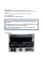
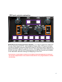
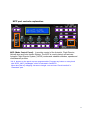
MCP combo panel
USER MANUAL (MEA2.520-26OCT09A)
Please read this manual before operating your units and keep it for future reference.
VRinsight
Virtual Reality Insight
Virtual Reality Insight
All stated here is subject to change without advanced notice for improvement.
Tel : +82-31-284-7090~91 Fax : +82-31-284-7092 E-mail : [email protected] Web site : www.vrinsight.com
1
BEFORE USE : Thanks for purchasing VRi’s MCP Combo panel.
Before operating your units, please read through this manual and keep it for future
reference.
For any further question, visit www.wilcopub.com or contact us below:
Fax : +32-2-33107 51
E-mail (Support team) : [email protected]
NOTE : This manual could be redistributed unless you modify the contents.
This manual has been written out on a Serial FP v2/Jet Liner’s MCP combo
panel basis.
All software (& software versions) stated here (MEA2.520-26OCT09A) is subject
to change without advanced notice for improvement.
If you want to download the latest driver version for panel & application
programs, visit www.vrinsight.com
Box contents
2
VRinsight
MCP combo panel
The MCP combo panel of VRinsight features various types of aircrafts’ panel
with full control complement ; default aircrafts of MSFS, most freeware and
commercial add-on aircraft (Wilco’s B737 Classic, PMDG’s B737NG & 744, LevelD’s B767-300 and PSS’ A319,320,330,340). It is completely interfaced with MSFS9
and MSFSX through add-on software *SerialFP2” which enables MCP combo
panel to perform full simulation with simple connection your computer through USB.
Package including universal power supply adaptor (DC 5V).
The MCP combo panel is comprised of EFIS, MCP & COM (Instrument Radio)
part to understand advanced flight controls for beginners and less advanced users
starting flight simulation games at a first step.
Each control part; EFIS, MCP & COM has push buttons, rotary knobs, toggle
S/Ws and/or 2 line character type LCDs offers actual flight circumstance with full
control complement.
•SerialFP2 software supports all functions to MCP combo panel
• MCP combo panel consumes high power. To avoid malfunction , do not use many other
USB interfacing devices. We recommend using external power supply (DC 5V adaptor)
• If you want to use a USB hub, be sure that the USB hub is USB 2.0 compliant.
Otherwise it may cause a malfunction.
3
EFIS part
MCP part
COM part
The MCP combo panel features the following controls:
EFIS part :
- Toggle S/Ws for VOR1,2/ADF1,2 .
- Knob S/Ws for MINS, BARO, CTR ; ND mode selector and TFC.
- Push buttons for FPV, MTR, WXR, NAVAID, WPT, ARPT, DATA
- All buttons and rotary knobs are user-programmable
MCP part :
- 2 line character type LCD displaying SPD, HDG, ALT and Pitch & Bank
at Autopilot Status
- On/Off toggle S/Ws for F/D, A/T
- Thrust mode selection buttons: N1, SPD, FLCH
- Push buttons for HDG SEL & HOLD, ALT HOLD, V/S SEL, TOGA, CRZ,
VNAV, LNAV, CMDA, CMDB, CMDC, LOC, CWSA(Y/D), CWSB(BCRS),
APP
- On/Off toggle switch for DISENGAGE.
COM(Instrument Radio) and 8-User programmable control part :
- 2 line character type LCD displaying COM & NAVAID Frequencies,
DME distance, speed, VOR ID & CRS, Squawk code
- 5 push buttons for Instrument radio function selector
(COM, NAV, ADF, DME, TRANSPONDER)
- Rotary knob for NAVAID’s frequency change, CRS/OBS, Squawk Code
- TFR button for activating stand-by frequency
- 8 User programmable control buttons
4
Features
• Integrated unit with full radio stack function : EFIS part, MCP part, COM
part
• All necessary buttons, switches and LCD panel to input SPD, VOR, HDG
and all other functions for getting close to real flight.
• Offer actual flight circumstance via MCP combo panel with full control
complement
• Full metal cases
• One year warranty
Technical specifications
• USB interface type to computer
• External power requirement : DC 5V adaptor or USB power supply type to
MCP combo panel. We recommend using DC 5V adaptor.
• 50cm(W) x 14cm(H)
• 4Kg
Compatibility software
• Flight simulator 2004 / FSX by Microsoft
Operating software
• SerialFP2
5
SerialFP2 Installation
With MCP combo panel, an “Install DVD” is included. When you insert it in DVD driver
of your computer, “VRinsight HTML” document will be shown. Then click “SerialFP2”
(operating software) and install it at a proper folder.
“SerialFP2” is the main operating software of VRinsight used for all VRinsight flight
panels.
SerialFP2 software supports full functions of MCP combo panel and completely
interfaced with MSFS9 and MSFSX enables full simulation with simple connection with
your computer through USB.
Be sure that when installing SerialFP2, “Install USB-Serial Driver” must be checked.
After installation, you can find “SeiralFP2” in “All programs” of “Start menu”.
USB Connection
The connection between MCP combo panel and your computer is made using a USB
cable that plugs into an USB port on your computer. If you want to use a USB hub, be
sure that the USB hub is USB 2.0 compliant. Otherwise it may cause a malfunction.
When you connect MCP combo panel to your computer at first, your computer will
detect it and will describe the process step by step.
Power Connection
Power supplying of MCP combo panel is done by universal power supply adaptor DC
5V (Included in package) and/or USB port of your computer. Make sure that before
trying to operate MCP combo panel, you must confirm the USB connection first in
order to prevent malfunction.
Before trying to operate, be sure that LCD displaying is shown.
Run “SerialFP2”
When you confirm all setup processes done; “SerialFP2” installation, “USB
connection” and “Power connection”, you are ready to operate MCP combo panel.
Download & install “FSUIPC”
Refer to “Download & install FSUIPC” at “Download” part of www.vrinsight.com
FS 9 requires FSUIPC v3.80 or later. FSX requires FSUIPC v 4.26 or later.
6
Double click shortcut of “SerialFP2” or find it in “All programs” of “Start menu .
If everything is done properly, below window will be shown.
7
EFIS part controls explanation
EFIS (Electronic Flight Instrument System) : It is used to control the respective
Primary Flight Display (PFD) and Navigation Display (ND). EFIS panel includes
controls for selecting various modes and ranges on the ND as well as switches to
display NAVAIDS, waypoint, airports and etc. Two toggle S/Ws allow displaying of
the left and right VOR and ADF bearing pointer on the ND. Controls are available
to set barometric altimeter settings for displaying on the PFD.
•The functions of each button and knob can be differed from the explanation according to
the aircraft's implementation. Also, buttons and knobs are user programmable for another
functionality.
8
L or R VOR / ADF switch : Select NAVAID between VOR or
ADF.
Toggle
S/W
MINS
Pushing : Resets or blanks PFD display
Rotating : Adjusts PFD radio or baro minimums altitude
BAR
O
Pushing : Displays preselected barometric setting
Rotating : Adjusts barometric reference
CTR
Pushing : Displays full compass rose for APP, VOR and
MAP modes. Subsequent pushing alternates between
expanded and centered displays
Rotating : Changes ND(Navigation Display) mode among
APP, VOR, MAP, PLN.
APP : Approach mode, displays ILS, localizer and glide
slop information in heading up format. Reference ILS
receiver, ILS frequency or identification, course and DME
Rotate &
Push
VOR : VOR mode, displays VOR navigation information in
heading up format. Reference VOR receiver, VOR
frequency or identification, course and DME and
TO/FROM information
MAP : Map mode, displays FMC-generated route and
map information airplane position, heading and track in
tracking-up format. Displays waypoints, including the
active waypoint within the selected range. Also displays
VNAV deviation
PLN : Plan mode, displays a stationary true north-up route
depiction. Route may be reviewed selecting “STEP” at
using the CDU legs
TFC
Pushing : Displays TCAS information on the ND
Rotating : Selects the desired ND nautical miles range
scale
9
FPV
MTRS
Displays flight path vectors on PFD
Displays PFD altitude meters indications
MAP buttons : Selects or removes ND information. More than
one displayed may be selected at a time
WXR
Displays weather radar information
STA
Displays high and low altitude navigation aids in the 10, 20 or
40 NM range and high altitude navigation aids only if range is
selected above 40 NM
WPT
Displays waypoints if range selector is set to 10, 20 or 40 NM
ARPT
Displays airports information ; ID, distance and etc
DATA
Displays the FMC estimated time of arrival and altitude at
each waypoint
Push SW
POS
TERR
Displays ADIRU and both GPS positions and VOR raw data
radials extended from the nose of the airplane to the stations.
Displays the Enhanced Ground Proximity Warning System
terrain data on the ND. The data is mutually exclusive of
WXR data, so selecting one deselects the other.
Between WXR and TERR the priorities are :
•Terrain warning
• Predictive wind shear warning
• Terrain caution
• PWS caution
10
MCP part controls explanation
MCP (Mode Control Panel) : It provides control of the Autopilot, Flight Director,
Altitude alert and Auto-throttle System. The MCP is used to select and activate
Autopilot Flight Director System, (AFDS) modes and establish altitudes, speeds and
climb/descent profiles.
* All of buttons on the panel are user programmable. Program any button or rotary knob
with “SPF2_MCP_KeyMapper” which is included in SerialFP2.
More about the key-mapping visit www.vrinsight .com and see “Panel interface” in
“Download” part.
11
A/T
Toggles Auto-Throttle Mode On/Off
F/D
Activates or Deactivate Flight Director(F/D)
The commands bar on the PFD annunciated when activated.
DISE
NGA
GE
CRS
Controls autopilot engagement
Rotating : Decides the course (OBS) to NAVAID(VOR)
SPD
Rotating : Decides the speed of airplane to fly
HDG
Rotating : Decides the heading of airplane to fly
ALT
Rotating : Decides the altitude of airplane to fly
V/S
Rotating : Decides the vertical speed of airplane to fly
12
TOGA
CRZ
N1
SPD
In takeoff / go-around / Cruise : Generates certain
torque with A/T is On.
FLCH
Changes the flight level to the altitude indicated on LCD
Displayed on PFD pitch flight mode annunciator as pitch
mode and auto-throttle automatically engaged.
HDG
SEL
HDG
HLD
Autopilot heading mode: Heading Select(HDG
SEL), Heading Hold (HDG HLD)
HDG SEL sets heading on LCD, PFD and ND
HDG HLD holds heading established at wings level.
ALT
HLD
Engages Altitude as a pitch mode and displays it PFD pitch
flight mode annuniciator. AFDS commands pitch to maintain
Altitude
VNAV
Takes over and controls the pitch and airspeed in accordance
with a pre-set profile(If VNAV and Auto-throttle armed). VNAV
engages above 400 feet radio altitude
LVNA
CMD
A
LOC
Makes airplane tracking Magenta line on the ND. LNAV
engages if airplane is above 50 feet radio altitude, within 2.5
NM of active leg, and within path capture parameters of ground,
intercept angle and bank angle, to active leg.
CMD
B
CMD
C
Engages A/P (A, B, C is the number of
/AP and is different on the type of
airplane)
Engages Localizer and AFDS as roll mode to capture and
track inbound on front course
13
V/S
FPA
APP
Y/D
BCRS
Engages vertical speed or flight path angle as pitch mode
Engages Localizer as roll mode and glide slop as pitch mode
AFDS captures and tracks localizer in LOC mode and capture
glide slop in glide slop mode. Localizer captures when
intercept track angle is within 120 degrees of localizer course.
Glide slop captures when intercept track angle is within 80
degrees of localizer course.
Yaw Damper
Back-Course Mode
LCD display : It shows SPD, HDG, ALT, V/S and Autopilot Status
or Aircrafts attitude (Pitch & Bank)
14
COM part controls explanation
COM (Instrument Radio) Panel & 8-User Programmable Buttons :
It provides radios stack function and user programmable control buttons.
* All of buttons on the panel are user programmable. Program any button or rotary knob
with “SPF2_MCP_KeyMapper” which is included in SerialFP2.
More about the key-mapping visit www.vrinsight .com and see “Panel interface” in
“Download” part.
15
Selection buttons : Buttons are used to carry out a pre-defined
function that has been assigned to it by the current menu
GEAR
UP
GEAR
OFF
GEAR
DN
FLAP
UP
FLAP
DN
A.BR
K
RTO
A.BR
K
DEC
A.BR
K
INC
8 User programmable control buttons according to the aircraft. Above
definitions are the example when it’s used with Level-D 767-300ER.
COM
NAV
ADF
DME
TRN
Select one of 5 Radio Panel functions.
Swap COM/NAV’s standby to Active frequency
AUX
AUX button.
Rotate to select COM/NAV/ADF frequency, Squawk
Pushes to change the digit
LCD display : It shows the information of COM1 &2, NAV1 & 2,
ADF, DME, TRNANSPONDER(SQUAWK CODE)
Converts power source
USB : Supplied the power from USB port
Neutral : Power off
EXT : Supplied the power from external power supplier (DC
5V adaptor)
16
Panel installer launch
: Panel installer will copy & paste all necessary panel data to work MCP combo.
automatically. Be sure “Panel Installer” should run before running SerialFP2.
* Once the panel is installed, aircraft configuration is kept.
After “SerialFP2” installation, you can find “Panel Installer”.
How to use “Panel Installer”.
1.Run “Panel Installer” first
17
1
2
3
4
5
1.MSFS-Root Path : Browse the path where “Flight Simulator 9” or “Microsoft Flight
Simulator X” is installed.
* If “Flight Simulator 9” or “Microsoft Flight Simulator X” is installed other “Drive” or
“Directory”, find the path and click “OK”.
* if you select a wrong path, “Status” window displays error message.
18
2. VRinsight panel : Drop down and select your panel.
3. Aircraft : Drop down and select your aircraft.
4. Run : Copy & paste all necessary panel data to work MCP combo automatically.
* If you select an aircraft for FS9 and the “MSFS-Root Path” is for FSX, “Status”
window displays error message and all necessary panel date will not be
automatically copied & pasted. And vice versa.
19
5. Status : Inform current status.
* If everything is done properly, you will get below message
20
Preparing MCP combo before Flight
Step 1 : Initial check up
Before flight with MCP combo, please check the followings are done
A. Install of SerialFP2.
* Check that “Install USB-Serial Driver” is checked or not.
B. Confirm that proper version of FSUIPC is installed or not
(FSUIPC v3.80 or later for FS9 / FSUIPC v4.26 or later for FSX)
C. Confirm the USB connection.
* Check that the USB port of your computer is dead or not
* Check that if you use USB hub, be sure that the USB hub is USB 2.0 compliant.
D. Confirm that “Panel Installer” is executed or not.
Step 2 : Run flight simulator (MSFS9 / MSFSX)
A. Run flight simulator (MSFS9 / MSFSX).
B. Select Aircraft.
21
Step 3 : Run panel linking application software “SerialFP2”.
When you run “SerialFP2”, below window will be shown.
1
2
3
4
5
7
6
8
1 : Number of COM(USB) port
2 : Type of panel
3 : Firm ware version
4 : Aircraft selection
5 : Link to game
6 : Software loading sequence change
Original sequence
(MSFS loading first => SerialFP2 running)
New sequence
(MSFS loading / SerialFP2 running first
=> SerialFP2 running / MSFS loading)
7 : Input test for panel
8 : Link test for panel with game
Drop down “Select Aircraft” and press “Load FS Module”.
22
Key-command sticker
key-command sticker is provided with product and enclosed DVD has
“KeyCap_Decal.pdf” file for “LETTERING” based on MSFS9 / MSFSX . Please print it
out and use for your purpose.
Button & Rotary knob assignment
The predefined button & Rotary knob assignments of all aircrafts supported are located
at C\Program Files\SerialFP2\Aircraft\MCP_CDU.
Key mapping & Mouse key
How to make your own key assignment by key-mapping & Mouse key is explained at
“Panel Interface”.
You can find it “Download” part of VRinsight web-site / www.vrinsight.com.
23
COM part explanation.
MCP combo panel is incorporated with MCP, EFIS and radio panel. Radio panel used
for all aircrafts features frequency input (COM / NAV / ADF), information display (VOR
/ DME) and Squawk code input to Transponder.
After converting DME screen, input OBS1, OBS2 value with rotary switch.
- COM1,COM2 : Inputs ATC and communication frequency.
- NAV1, NAV2 : Inputs frequency of radio navigation facility (VOR, ILS/DME).
- ADF : Inputs ADF frequency.
- DME : Displays frequency information of radio navigation facility (VOR,ILS/DME)
inputted by NAV1, NAV2. Also displays ID, distance & deviant speed (from
radio navigation facility) and approaching speed (to radio navigation facility).
- TRN : Inputs Squawk code.
Radio panel has selection buttons (COM/NAV/ADF/DME/TRN).
TFR button for activating stand-by frequency. Rotary-key for changing digit.
As pushing each function button, LCD displays various information
24
Rotating rotary switch changes stand-by frequency (or squawk code).
Pushing rotary switch changes a digit. TFR switch(< - X - >) activates current stand-by
frequency (or squawk code). DME just displays information of radio navigation facility
tuned to navigation.
With SquawkBox3 of VATSIM, TRNsponder offers “MODE-C NORM/STBY” conversion
function.
Power source select switch :
Convert switch when you change power source
25
Trouble shooting
ON/OFF trouble - USB port and power supply.
MCP combo panel is high power consuming device. Connect the panel to USB port on
your computer directly. When it works incorrectly, using external power supplying AC-toDC adaptor is recommended.
Adaptor 5V, 1A
If DC power adaptor is used, be sure power switch position to EXT.
INITIAL LCD DISPLAY trouble - Link test.
After connection, check the initial messages (MCP & COM part). If no message shown,
confirm whether you have checked “Install USB Serial Driver” of “SerialFP2” setup
wizard. If SerailFP2 can not find COM port for CDU, check Device Manager whether
CDU has been assigned or not.
If nothing is display after power connection, use other USB ports. Some USB port is
dummy port.
Initial LCD display
MCP part
COM part
26
LCD BRIGHTNESS trouble - LCD contrast
When the panel is plug into your computer, initial messages are displayed on LCD
after power-on selftest. If it’s dimmed or cloudy, tune the contrast.
Tune LCD brightness
dark
bright
PANEL FUNCTION trouble 1 - Panel function test
When MCP combo panel is linked to “SerialFP2” software correctly, control linkage
and functioning of the panel can be tested without starting flight simulator.
(1) Check the check box.
(2) Press buttons or rotate rotaryencoder of your MCP combo panel.
Commands are transferred to your
computer and result will be displayed
on software.
Some transferred values, i.e. SPD,
HDG, and ALT, are identical to
displayed on LCD.
27
PANEL FUNCTION trouble 2- FSUIPC check
Download & install FSUIPC is required for MCP combo panel use with Microsoft’s
Flight Simulator. If you didn’t download & install, do it now. Basic function of FSUIPC is
enough to operate. No registration is required.
Also check “FSUIPC.dll” file is in “\Program Files\Microsoft Games\Flight Simulator9
\Modules”. Further information, see “download & install FSUIPC” part.
PANEL FUNCTION trouble 3 – Procedure check
1) Download & install FSUIPC
2) Update your FS (In FSX case, update your FSX with SimConnect)
3) Install “SerialFP2”.
4) Run “Panel Installer”.
5) Run FS9 / FSX
6) Run “SerialFP2”
7) Select your aircraft
28