1
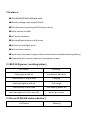
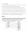
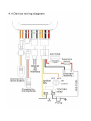
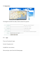
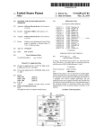
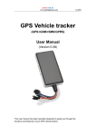
GPS Vehicle tracker
( GPS+GSM+SMS/GPRS )
User Manual
(Version 1.1)
Please read this manual carefully before attempting installation and online
activation.Pictures are for indication and illustration purposes only.
1.
2.Features:
●GSM 850/900/1800/1900Quad band
●Wide for voltage input range:9-36Vdc
●GPS continuous positioning,GPRS timing interval
●Check location via SMS
●ACC ignition detetion
●Tele-cutoff(petrol/electricity)function
●SOS alarm and burglar alarm
●voice monitor function
●Alarm when the power supply is disconnected intentionally(With backup battery)
●Compatible with rxternal connection through(serial port)
2.1RED LED(power/working/status)
LED Status
Meaning
Flashing(interval0.1s)
Low battery indication
Continuously in bright state
Charging
Slow flashing(interval0.2s)
Full charge
Continuously in dark state
Low battery/power off
Slow flashing(flash0.1after every2s)
Working normally
2.2Green LED(GSM status indicator)
LED Statue
Meaning
Quick flash(interval0.1s)
GSM initialization
Slow flashing(flash 0.1s af ter every2s)
Receive GSM signal normally
Continuously in bright state
GSM conversation/Start GPRS
Continuously in dark state
GPS notlocated
2.3Blue LED (GPS status indicator)
LED Status
Meaning
Flashing(interval0.1s)
Searching GPS signal
Continuously in bright state
GPS located
Continuously in dark state
GPS notlocated
2.4 lgnition detection indication
Three(blue/red/green)LEDs are in cycling flashing.
4.Method of installation
4.1.Preparation before installation
4.1.1 Open the packing box to check whether the type of device is correct and whether
the accessories are included, or else please contact your distributor.
4.1.2Choose SIM card: each device needs to insert a GSM SIM card. Please refer to the
distributor’s suggestions to choose the SIM card.
4.1.3 Installing SIM card: The SIM card slot is on the right side of device. Open the SIM
card sillcon seal, then insert the SIM card to the slot (do not insert the SIM card
backwards).When the SIM card is ready you will hear aclick. Or else please insert again
and then replace the sillcon seal.
Note:
Power off before installing or removing the SIM card.
The SIM card used should be enabled for GPRS.
The SIM card used should be enabled for called ID.
If there is a power on password, or pin, please cancel it;
Ensure the SIM card can send and receive SMS.
4.2 Installation
The device installation is covert. Please refer installation to an auto electrical contractor.
NOTE:
4.2.1 To prevent theft of the device, it should be installed as covertly as possible. Covertly
installation is suggested.
4.2.2 Avoid placing the device close to higher power electrical devices, such as reversing
radar, anti-theft device or other vehicle communication equipment;
4.2.3The device should be fixed into position with cable ties or wide double-side tape.
4.2.4 The device has built-in GSM antenna and GPA antenna. During installation, please
make sure the receiving side face is up, with no metal object above the device to interfere
with GPS reception. The following places are suggested for installation: shelter in the
decorated board below the front windshield; shelter around the front instrument panle
(non-metallic material face); in the decorated board below back windshield;
Notice:
If the windshield is pasted with metal thermal-protective coating or heating coating. It
may affect the receiving signal. In this case,please change the installation place.
Line No.
Speciflcation
Color
Instruction
1.2
Keypod
Orange/Orange
Connect to SOS button
3.4
MIC-,MIC+
Black/Red
Connect to Microphone
5
TX
Green
Sending data(TX)backup
6
RX
White
Receiving data (RX)backup
7
GND
Black
Ground wire
8
MOTOR
Yellow
Connect to relay control line
9
ACC
Orange
Connect to ACC ignltion
10
V-
Black(thick)
Vehicle12V/24V negative
storage battery
11
V+
Red(thick)
Vehicle12V/24V positive
storage battery
Notes of the relay wiring
The relay wiring of pump: oil connectors of both ends are affine white line (85)and a fine
yellow line (86).The fine white line (85) is connected to vehicle positive power (+12V).The
fine yellow line is connected to the device relay control line.
Cut off the positive connection line of the pump: then connect in series to the relay N.C
contact (thick green line 87a) and the other end relay COM contact (thick green line 30).
5. Cautions of device wiring
5.1 Power/ACC/Tele-cutoff(petrol/electricity)control line (4pin)
5.1.1 The standard voltage is 9V-36VDC.Please use the power Line which provided by the
manufacturer. The red line is the positive. The black line is the negative. The negative
should earth alone or link iron during installing. Do not connect it to other ground wire.
5.1.2 ACC line (orange) is connected to the ACC switch of the vehicle. Please make sure to
connect the ACC line. The tracker will decide whether to enter ignition detection
according to ACC status. If do not connect to ACC line, the device will enter ignition
detection status. If the vehicle vibrates when moving, it will activate the vibration alarm.
If there is no need for the theftproof function, connect the ACC line to the positive in
parallel and keep high level.
5.1.3 Tele-cutoff (petrol/electricity) control line (yellow) is connected to pin 86 of the
Tele-cutoff (petrol/electricity) relay(equal to the yellow line of the relay socket).
5.2 USB cable (3 pin)
Firmware updating interface/expanded function to reserve space.
5.3 MIC line(3 pin)
Externally connect to microphone for voice monitor function.
5.4 SOS line (2 pin )
Externally connect to SOS switch for SOS function.
6.SMS command format
6.1. Set APN
Format: #802#APN letters or digits, 4-20 bits # Log user name letters or digits 4-20 bits in
# Log password letter or digits 4-20 bits in # terminal password 4 bits ##
The default APN is CMNET, if the APN doesn’t have login user name and password, it can
be set 0.
Example 1: #802#0#0#0#0000##
APN is CMNET, no login user name, no login password
Example 2: #802#CCDLEN#QIUXIA.21#RX0000#0000##
APN is CCDLEN; the login user name is QIUXIA.21 and login password is RX0000.
Note: The default APN of this product is CMNET.
6.2.
Set Server connection
Format: #803# Fixed IP address# port number#4-digit password##
This command is used to set GPRS center server address, which could be fixed IP number.
After the setup is successful, the module will send a reply with ‘&803&successful
setting&&’ or ‘&803&PASSWORD ER&&’ if the password is wrong.
Example: #803# 59.188.20.67#8545#0000##
Setup via domain name:
Example: #803#www.gps288.com#8545#0000##
6.3.
Regular Upload Interval Setup
The defaulted factory upload interval of this device is 2 minutes for getting the point and
10 minutes for uploading one piece of location information. The user may change such
parameter according to actual demand.
Format: #730# Sampling interval # Pieces of uploads # User password ##
For example: #730#20#4#0000##
Note: The parameter “20” indicates getting one point every 20s; after getting points
accumulatively for 4 times, upload one piece of location information with the upload
interval as 20*4=80s.
6.4. SMS location inquiry
Format: 888+0000 (default password is 0000)
For example you send 8880000 to the tracker, you will get a reply SMS with link.
http//map.google.com/?q=22.677327N,114.120738E
SPEED:0.22240KM/H
Time:10:47:18 Date:03/05/11
IMEI:353509000924608
Visit the link by your phone or computer; you will know the name of the location in
detail.
6.5. Set Center Number
Set the center number by SMS through mobile phone. If the setup is successful, the
sender will receive “CONFIG OK” response message from the tracker
Format: #710# center number # user password ##
For example: #710#134xxxxxxxx#0000##
Note: All alarming information thereafter including SOS, low power, electronic fence
etc. will be sent to this number. 0000 is the default password.
6.6. Set pre-stored numbers
Before setting center number, the device will respond to command from any mobile
phone NO. After setting successfully; the device will not respond to other numbers except
the pre-set number. 9 numbers can be pre-set at most.
Format:#711#phone number # password d# serial##
For example:You want to set three stored numbers
#711# Phone number 1#0000#1## ---------------The first number
#711#phone number 2#0000#2## ----------------The second number
#711#phone number 3#0000#3## ----------------The third number
Only one phone number can be set per time, as above mentioned three numbers need to
send SMS three times separately. The new numbers will replace the old numbers, and it
will send confirmation to the sender if the password is right….CONFG OK
6.7. SOS button(Emergency call button)
In case of emergency, please press SOS button over 3 seconds, an emergency will be
reported to center number with current location, and call the pre-set numbers in turn.
6.8. Cut power supply/ oil supply by SMS
Format: 232+password
Example: 2320000
After sending command successfully, the tracker will return a message “SET OK” and cut
power supply of the vehicle.
6.9. Resume power supply and oil supply by SMS
Format: 230+password
Example: 2300000
After sending command successfully, the tracker will return a message “SET OK” and
resume power supply and oil supply of the vehicle.
6.10. Change the password
Format: #770# new password # old password ##”
Example: #770#1111#0000##
After sending command successfully, the tracker will return a message “CHANGE OK”.
And the user password will be changed to: 1111.
Remind: Now all set-up format’s password change to “1111”
6.11. E-fence set up
Set up an e-fence for the tracker to restrict its movements within an area. The tracker will
send the message to the authorized numbers when it goes beyond the district. If the
setting is correct, the tracker will reply CONFIG OK to the sender, and if the password is
wrong, it will reply PASSWORD ER.
Tips: Only pre-set number is set successfully, this function can work
Format: #750#radius (5 digits)#sampling interval (minutes)#password # #
For example: #750#500#5#0000##
A round fence with the radius of 500 meters, the current location as center is set.
When the tracker goes out this area, the tracker will send alarm information “OBJECT
OUT” to the center number.
6.12. Cancel E-fence
Format: #760#password##
Example: #760#0000##
After the tracker receiving this command, all fence settings will be cancelled, and
return a SMS “CONFIG OK”. The device will reply “PASSORD ER” if the format’s
password is wrong.
6.13.
Auxiliary Functions
(1)#901## Command of reading user parameters;
(2)#902## Command of reading GPRS parameters
(3)#903## Restart command
(4)#904## GPRS connection command
(5)#905## GPRS disconnection command
7.
Tracking on platform
Please visit http://www.gps288.com for online real-time tracking and fleet management.
NOTE: For online real-time tracking, please make sure you have connected the server
successfully (refer to 5.8), set APN successfully (refer to 5.9) and open GPRS upload
function (refer to 5.10)
7.1. Registration
Click Register and fulfill the table, submit and wait for approval.
7.2.
Login
There are 2 options for login.
Account: for group users
Car/IMEI No.: for end users
After you login, you will see the following page.
7.3. Target tracking
Click target and you can see the equipment list, click the equipment you want to track
and you can see the detailed information.
Click Image, you can see the real view.
For other fleet management function, please refer to our user’s manual of platform.
NOTES
1. This non-waterproof equipment, please be sure to have waterproof bag.
2. This equipment has to work with GSM network.
3. Please ensure that there are enough expanses in SIM card in order to avoid the
inconvenience of using.
4. This equipment cannot work in the power failure state and outside the service areas,
even if the registered users.
5. This equipment supports GPS and GSM/GPRS double positioning, regarding as the
same with the GPS positioning results.
6. Please use this equipment in the legal areas. The consequences of any violation of the
law will be undertaken by the users themselves.