1
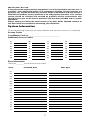
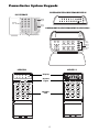
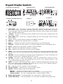
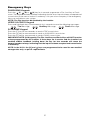
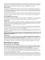
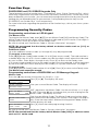
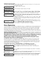
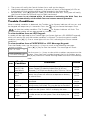
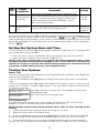
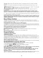
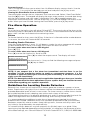
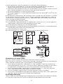
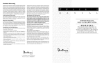
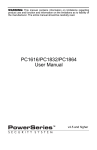
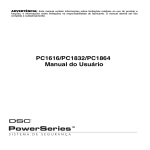
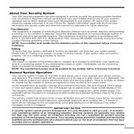
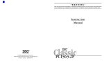
•WARNING• This manual contains information on limitations regarding product use and function and information on the limitations as to liability of the manufacturer. The entire manual should be carefully read. User Manual ™ Software Version 2.4ZD IMPORTANT - READ CAREFULLY: DSC Software purchased with or without Products and Components is copyrighted and is purchased under the following license terms: • This End-User License Agreement (“EULA”) is a legal agreement between You (the company, individual or entity who acquired the Software and any related Hardware) and Digital Security Controls, a division of Tyco Safety Products Canada Ltd. (“DSC”), the manufacturer of the integrated security systems and the developer of the software and any related products or components (“HARDWARE”) which You acquired. • If the DSC software product (“SOFTWARE PRODUCT” or “SOFTWARE”) is intended to be accompanied by HARDWARE, and is NOT accompanied by new HARDWARE, You may not use, copy or install the SOFTWARE PRODUCT. The SOFTWARE PRODUCT includes computer software, and may include associated media, printed materials, and “online” or electronic documentation. • Any software provided along with the SOFTWARE PRODUCT that is associated with a separate end-user license agreement is licensed to You under the terms of that license agreement. • By installing, copying, downloading, storing, accessing or otherwise using the SOFTWARE PRODUCT, You agree unconditionally to be bound by the terms of this EULA, even if this EULA is deemed to be a modification of any previous arrangement or contract. If You do not agree to the terms of this EULA, DSC is unwilling to license the SOFTWARE PRODUCT to You, and You have no right to use it. SOFTWARE PRODUCT LICENSE The SOFTWARE PRODUCT is protected by copyright laws and international copyright treaties, as well as other intellectual property laws and treaties. The SOFTWARE PRODUCT is licensed, not sold. 1. GRANT OF LICENSE This EULA grants You the following rights: (a) Software Installation and Use - For each license You acquire, You may have only one copy of the SOFTWARE PRODUCT installed. (b) Storage/Network Use - The SOFTWARE PRODUCT may not be installed, accessed, displayed, run, shared or used concurrently on or from different computers, including a workstation, terminal or other digital electronic device (“Device”). In other words, if You have several workstations, You will have to acquire a license for each workstation where the SOFTWARE will be used. (c) Backup Copy - You may make back-up copies of the SOFTWARE PRODUCT, but You may only have one copy per license installed at any given time. You may use the back-up copy solely for archival purposes. Except as expressly provided in this EULA, You may not otherwise make copies of the SOFTWARE PRODUCT, including the printed materials accompanying the SOFTWARE. 2. DESCRIPTION OF OTHER RIGHTS AND LIMITATIONS (a) Limitations on Reverse Engineering, Decompilation and Disassembly - You may not reverse engineer, decompile, or disassemble the SOFTWARE PRODUCT, except and only to the extent that such activity is expressly permitted by applicable law notwithstanding this limitation. You may not make any changes or modifications to the Software, without the written permission of an officer of DSC. You may not remove any proprietary notices, marks or labels from the Software Product. You shall institute reasonable measures to ensure compliance with the terms and conditions of this EULA. (b) Separation of Components - The SOFTWARE PRODUCT is licensed as a single product. Its component parts may not be separated for use on more than one HARDWARE unit. (c) Single INTEGRATED PRODUCT - If You acquired this SOFTWARE with HARDWARE, then the SOFTWARE PRODUCT is licensed with the HARDWARE as a single integrated product. In this case, the SOFTWARE PRODUCT may only be used with the HARDWARE as set forth in this EULA. (d) Rental - You may not rent, lease or lend the SOFTWARE PRODUCT. You may not make it available to others or post it on a server or web site. (e) Software Product Transfer - You may transfer all of Your rights under this EULA only as part of a permanent sale or transfer of the HARDWARE, provided You retain no copies, You transfer all of the SOFTWARE PRODUCT (including all component parts, the media and printed materials, any upgrades and this EULA), and provided the recipient agrees to the terms of this EULA. If the SOFTWARE PRODUCT is an upgrade, any transfer must also include all prior versions of the SOFTWARE PRODUCT. (f) Termination - Without prejudice to any other rights, DSC may terminate this EULA if You fail to comply with the terms and conditions of this EULA. In such event, You must destroy all copies of the SOFTWARE PRODUCT and all of its component parts. (g) Trademarks - This EULA does not grant You any rights in connection with any trademarks or service marks of DSC or its suppliers. 3. COPYRIGHT - All title and intellectual property rights in and to the SOFTWARE PRODUCT (including but not limited to any images, photographs, and text incorporated into the SOFTWARE PRODUCT), the accompanying printed materials, and any copies of the SOFTWARE PRODUCT, are owned by DSC or its suppliers. You may not copy the printed materials accompanying the SOFTWARE PRODUCT. All title and intellectual property rights in and to the content which may be accessed through use of the SOFTWARE PRODUCT are the property of the respective content owner and may be protected by applicable copyright or other intellectual property laws and treaties. This EULA grants You no rights to use such content. All rights not expressly granted under this EULA are reserved by DSC and its suppliers. 4. EXPORT RESTRICTIONS - You agree that You will not export or re-export the SOFTWARE PRODUCT to any country, person, or entity subject to Canadian export restrictions. 5. CHOICE OF LAW - This Software License Agreement is governed by the laws of the Province of Ontario, Canada. 6. ARBITRATION - All disputes arising in connection with this Agreement shall be determined by final and binding arbitration in accordance with the Arbitration Act, and the parties agree to be bound by the arbitrator’s decision. The place of arbitration shall be Toronto, Canada, and the language of the arbitration shall be English. 7. LIMITED WARRANTY (a) NO WARRANTY - DSC PROVIDES THE SOFTWARE “AS IS” WITHOUT WARRANTY. DSC DOES NOT WARRANT THAT THE SOFTWARE WILL MEET YOUR REQUIREMENTS OR THAT OPERATION OF THE SOFTWARE WILL BE UNINTERRUPTED OR ERROR-FREE. (b) CHANGES IN OPERATING ENVIRONMENT - DSC shall not be responsible for problems caused by changes in the operating characteristics of the HARDWARE, or for problems in the interaction of the SOFTWARE PRODUCT with non-DSC-SOFTWARE or HARDWARE PRODUCTS. (c) LIMITATION OF LIABILITY; WARRANTY REFLECTS ALLOCATION OF RISK - IN ANY EVENT, IF ANY STATUTE IMPLIES WARRANTIES OR CONDITIONS NOT STATED IN THIS LICENSE AGREEMENT, DSC’S ENTIRE LIABILITY UNDER ANY PROVISION OF THIS LICENSE AGREEMENT SHALL BE LIMITED TO THE GREATER OF THE AMOUNT ACTUALLY PAID BY YOU TO LICENSE THE SOFTWARE PRODUCT AND FIVE CANADIAN DOLLARS (CAD$5.00). BECAUSE SOME JURISDICTIONS DO NOT ALLOW THE EXCLUSION OR LIMITATION OF LIABILITY FOR CONSEQUENTIAL OR INCIDENTAL DAMAGES, THE ABOVE LIMITATION MAY NOT APPLY TO YOU. (d) DISCLAIMER OF WARRANTIES - THIS WARRANTY CONTAINS THE ENTIRE WARRANTY AND SHALL BE IN LIEU OF ANY AND ALL OTHER WARRANTIES, WHETHER EXPRESSED OR IMPLIED (INCLUDING ALL IMPLIED WARRANTIES OF MERCHANTABILITY OR FITNESS FOR A PARTICULAR PURPOSE) AND OF ALL OTHER OBLIGATIONS OR LIABILITIES ON THE PART OF DSC. DSC MAKES NO OTHER WARRANTIES. DSC NEITHER ASSUMES NOR AUTHORIZES ANY OTHER PERSON PURPORTING TO ACT ON ITS BEHALF TO MODIFY OR TO CHANGE THIS WARRANTY, NOR TO ASSUME FOR IT ANY OTHER WARRANTY OR LIABILITY CONCERNING THIS SOFTWARE PRODUCT. (e) EXCLUSIVE REMEDY AND LIMITATION OF WARRANTY - UNDER NO CIRCUMSTANCES SHALL DSC BE LIABLE FOR ANY SPECIAL, INCIDENTAL, CONSEQUENTIAL OR INDIRECT DAMAGES BASED UPON BREACH OF WARRANTY, BREACH OF CONTRACT, NEGLIGENCE, STRICT LIABILITY, OR ANY OTHER LEGAL THEORY. SUCH DAMAGES INCLUDE, BUT ARE NOT LIMITED TO, LOSS OF PROFITS, LOSS OF THE SOFTWARE PRODUCT OR ANY ASSOCIATED EQUIPMENT, COST OF CAPITAL, COST OF SUBSTITUTE OR REPLACEMENT EQUIPMENT, FACILITIES OR SERVICES, DOWN TIME, PURCHASERS TIME, THE CLAIMS OF THIRD PARTIES, INCLUDING CUSTOMERS, AND INJURY TO PROPERTY. WARNING: DSC recommends that the entire system be completely tested on a regular basis. However, despite frequent testing, and due to, but not limited to, criminal tampering or electrical disruption, it is possible for this SOFTWARE PRODUCT to fail to perform as expected. Table of Contents About Your Security System . . . . . . . . . . . . . . . . . . . . . . . . . . . .1 General System Operation . . . . . . . . . . . . . . . . . . . . . . . . . . . . 1 System Information . . . . . . . . . . . . . . . . . . . . . . . . . . . . . . . . . . 2 Access Codes . . . . . . . . . . . . . . . . . . . . . . . . . . . . . . . . . . . . . . 3 PowerSeries System Keypads . . . . . . . . . . . . . . . . . . . . . . . . . . . . . . . 4 Keypad Display Symbols . . . . . . . . . . . . . . . . . . . . . . . . . . . . . . . . . . . 5 Emergency Keys . . . . . . . . . . . . . . . . . . . . . . . . . . . . . . . . . . . . . . . . . 6 Arming the System . . . . . . . . . . . . . . . . . . . . . . . . . . . . . . . . . . 7 Alternate Arming Methods. . . . . . . . . . . . . . . . . . . . . . . . . . . . . 7 Disarming the System . . . . . . . . . . . . . . . . . . . . . . . . . . . . . . . . 8 If An Alarm Sounds . . . . . . . . . . . . . . . . . . . . . . . . . . . . . . . . . . 9 Function Keys . . . . . . . . . . . . . . . . . . . . . . . . . . . . . . . . . . . . . 10 Programming Security Codes . . . . . . . . . . . . . . . . . . . . . . . . . 10 Zone Bypassing. . . . . . . . . . . . . . . . . . . . . . . . . . . . . . . . . . . . 11 User Function Commands. . . . . . . . . . . . . . . . . . . . . . . . . . . . .12 Trouble Conditions . . . . . . . . . . . . . . . . . . . . . . . . . . . . . . . . . 13 Setting the System Date and Time . . . . . . . . . . . . . . . . . . . . . 14 Testing Your System . . . . . . . . . . . . . . . . . . . . . . . . . . . . . . . . 14 Door Chime Feature . . . . . . . . . . . . . . . . . . . . . . . . . . . . . . . . 15 Keypad Options. . . . . . . . . . . . . . . . . . . . . . . . . . . . . . . . . . . . 15 Fire Alarm Operation . . . . . . . . . . . . . . . . . . . . . . . . . . . . . . . . 16 Household Fire Safety Audit . . . . . . . . . . . . . . . . . . . . . . . . . . 17 Fire Escape Planning. . . . . . . . . . . . . . . . . . . . . . . . . . . . . . . . 17 i IMPORTANT SAFETY INSTRUCTIONS To reduce the risk of fire, electric shock and/or injury, observe the following: • Do not spill any type of liquid on the equipment. • Do not attempt to service this product yourself. Opening or removing the cover may expose you to dangerous voltage or other risk. Refer servicing to qualified service personnel. Never open the device yourself. • Do not touch the equipment and its connected cables during an electrical storm; there may be a risk of electric shock. • Do not use the Alarm System to report a gas leak if the system is near a leak. REGULAR MAINTENANCE AND TROUBLESHOOTING Keep your Alarm Controller in optimal condition by following all the instructions that are included within this manual and/or marked on the product. CLEANING • Clean the units by wiping with a damp cloth only. • Do not use abrasives, thinners, solvents or aerosol cleaners (spray polish) that may enter through holes in the Alarm Controller and cause damage. • Do not use any water or any other liquid. • Do not wipe the front cover with alcohol. TROUBLESHOOTING Occasionally, you may have a problem with your Alarm Controller or telephone line. If this happens, your Alarm Controller will identify the problem and displays an error message. Refer to the provided list when you see an error message on the display. If additional help is required, contact your distributor for service. WARNING: This equipment, PC585 Alarm System, shall be installed and used within an environment that provides the pollution degree max 2 and over-voltages category II nonhazardous locations, indoor only. It is designed to be installed, serviced and/or repaired by service persons only [service person is defined as a person having the appropriate technical training and experience necessary to be aware of hazards to which that person may be exposed in performing a task and of measures to minimize the risks to that person or other persons]. For EU and Australian markets, the equipment is permanently connected; a readily accessible disconnect device shall be incorporated into the building installation wiring. For North America the equipment is a direct plug-in connection; the socket outlet shall be installed near the PC585 and shall be easily accessible. The plug of the direct plug-in transformer serves as the disconnect device. ii About Your Security System Your DSC security equipment has been designed to provide you with the greatest possible flexibility and convenience. Read this manual carefully and have your installer instruct you on your system's operation and on which features have been implemented in your system. All users of this system should be equally instructed in its use. Fill out “System Information” on page 2 with all of your zone information and access codes and store this manual in a safe place for future reference. Fire Detection This equipment is capable of monitoring fire detection devices such as smoke detectors and providing a warning if a fire condition is detected. Good fire detection depends on having adequate number of detectors placed in appropriate locations. This equipment should be installed in accordance with N.F.P.A. standard #72. (N.F.P.A., Batterymarch Park, Quincey MA 02269). Carefully review the Family Escape Planning guidelines in this manual. NOTE: Your installer must enable the fire detection portion of this equipment before it becomes functional. Testing To ensure that your system continues to functions as intended, you must test your system weekly. Please refer to “Testing Your System” on page 14 of this manual. If your system does not function properly, call your installing company for service. Monitoring This system is capable of transmitting alarms, troubles and emergency information over telephone lines to a monitoring station. If you inadvertently initiate an alarm, immediately call the monitoring station to prevent an unnecessary response. NOTE: The monitoring function must be enabled by the installer before it becomes functional. Maintenance With normal use, the system requires minimum maintenance. Note the following points: • Do not wash the security equipment with a wet cloth. Light dusting with a slightly moistened cloth should remove normal accumulations of dust. • Use the system test described in “Testing Your System” to check the battery condition. We recommend, however, that the standby batteries be replaced every 3-5 years. • For other system devices such as smoke detectors, passive infrared, ultrasonic or microwave motion detectors or glassbreak detectors, consult the manufacturer’s literature for testing and maintenance instructions. General System Operation Your security system is made up of a DSC control panel, one or more keypads and various sensors and detectors. The control panel will be mounted out of the way in a utility closet or in a basement. The metal cabinet contains the system electronics, fuses and stand-by battery. NOTE: Only the installer or service professional should have access to the control panel. All the keypads have an audible indicator and command entry keys. The LED keypads have a group of zone and system status lights. The LCD keypad has an alphanumeric liquid crystal display (LCD). The keypad is used to send commands to the system and to display the current system status. The keypad(s) will be mounted in a convenient location inside the protected premises close to the entry/exit door(s). The security system has several zones of area protection and each of these zones will be connected to one or more sensors (motion detectors, glassbreak detectors, door contacts, etc.). A sensor in alarm will be indicated by the corresponding zone lights flashing on a LED keypad or by written messages on the LCD keypad. 1 IMPORTANT NOTICE A security system cannot prevent emergencies. It is only intended to alert you and – if included – your monitoring station of an emergency situation. Security systems are generally very reliable but they may not work under all conditions and they are not a substitute for prudent security practices or life and property insurance. Your security system should be installed and serviced by qualified security professionals who should instruct you on the level of protection that has been provided and on system operations. Always ensure you obtain the latest version of the User Guide. Updated versions of this User Guide are available by contacting your distributor. System Information Fill out the following information for future reference and store this manual in a safe place. Access Codes Your Master Code is: ______________________________ Additional Access Codes: 01 09 17 25 02 10 18 26 03 11 19 27 04 12 20 28 05 13 21 29 06 14 22 30 07 15 23 31 08 16 24 32 Zone Information There are ________ active zones on the system. Zone Protected Area Zone Type 01 02 03 04 05 06 07 08 09 10 11 12 13 14 15 16 17 2 Zone Protected Area Zone Type 18 19 20 21 22 23 24 25 26 27 28 29 30 31 32 [F] FIRE [A] AUXILIARY [P] PANIC The Exit Delay Time is __________seconds. The Entry Delay Time is __________seconds. For Service Central Station Information: Account #: Telephone #: Installer Information: Company: Telephone #: Access Codes Access codes are used to arm and disarm the system. There are 33 access codes available: 1 Master Code and 32 regular access codes. Only the Master Code can be used to program additional security codes and to change other system features as well as to arm and disarm the security system. The Master Code will be supplied to you by your installer. All keypad entries are made by pressing one key at a time. All access codes can be programmed by following the procedure outlined in “Programming Security Codes” on page 10. NOTE: An access code can be a four or six digit number depending on how your installer has programmed your system. Ask your installer for more information regarding access codes. 3 PowerSeries System Keypads PK5508/PK5516/RFK5508/RFK5516 PC1555RKZ Status Lights [ Number Pad Zone Lights PK5500/PK5501/RFK5500/RFK5501/RFK5564 Emergency Keys 1 2 3 4 5 6 7 8 9 Reset * 0 # Quick Exit LCD5511 LED5511 Display System Lights Number Pad 4 Stay Away Chime Keypad Display Symbols LCD5501 Fixed Message PK5508/5516/RFK5508/5516 PK5501/RFK5501 LCD5501 ICON 5 9 14 7 LED5511 1 2 3 4 6 11 10 8 LCD5511 10 1 Clock Digits 1, 2 – These two 7 segment clock digits indicate the hour digits when the local clock is active, and identify the zone when the OPEN or ALARM icons are active. These two digits scroll one zone per second from the lowest zone number to the highest when scrolling through zones. 2 : (Colon) – This icon is the hours/minutes divider and will flash once a second when the local clock is active. 3 Clock Digits 3, 4 – These two 7 segment displays are the minute digits when the local clock is active. 4 1 to 8 – These numbers identify troubles when [,][2] is pressed. 5 Memory – Indicates that there are alarms in memory. 6 Bypass – Indicates that there are zones automatically or manually bypassed. 7 Program – indicates that the system is in Installer’s Programming, or the keypad is busy. 8 Away – Indicates that the panel is armed in the Away Mode. 9 Fire – Indicates that there are fire alarms in memory. 10 Stay – Indicates that the panel is armed in the Stay Mode. 11 Chime – This icon turns on when the Chime function key is pressed to enable Door Chime on the system. It will turn off when the chime function key is pressed again to disable Door Chime. 12 AM, PM – This icon indicates that the local clock is displaying 12 Hr. time. These icons will not be on if the system is programmed for 24 Hr. time. 13 ALARM – This icon is used with clock digits 1 and 2 to indicate zones in alarm on the system. When a zone is in alarm, the ALARM icon will turn on, and 7 segment displays 1 and 2 will scroll through the zones in alarm. 14 OPEN – This icon is used with clock digits 1 and 2 to indicate violated zones (not alarm) on the system. When zones are opened, the OPEN icon will turn on, and 7 segment displays 1 and 2 will scroll through the violated zones. 15 AC – Indicates that AC is present at the main panel. 16 System Trouble – Indicates that a system trouble is active. 17 System - Indicates one or more of the following: Memory – Indicates that there are alarms in memory. Bypass – Indicates that there are zones automatically or manually bypassed. System Trouble – This icon is displayed when a system trouble is active. 18 Ready Light (green) – If the Ready light is on, the system is ready for arming. 19 Armed Light (red) – If the Armed light is on, the system has been armed successfully. 5 Emergency Keys PK/RFK55XX Keypads Press the (F), (A) or (P) key for 2 seconds to generate a Fire, Auxiliary or Panic alarm. The keypad sounder will beep indicating that the alarm input has been accepted and transmission to the central station is underway. Ask your alarm company if the emergency keys are available on your system. NOTE: The Fire keys can be disabled by the installer. LED5511/LCD5511 Keypad Press and hold both keys simultaneously for 2 seconds to send the following messages: Fire Message, Auxiliary Message, Panic Message. PC1555RKZ Keypad Press the [F] key for two seconds to send a FIRE transmission. Press the [A] key for two seconds to send an AUXILIARY transmission. Press the [P] key for two seconds to send a PANIC transmission. IMPORTANT NOTE (All Keypads): The Fire, Auxiliary and Panic Keys will NOT function unless programmed by the installer. If these keys are in service and the installer has enabled audible feedback, holding down the key for two seconds will cause the keypad sounder to beep, indicating that the input has been accepted and transmission is underway. NOTE: In the U.S.A. the [A] and keys are programmed to be used for non-medical emergencies only, as per UL requirements. 6 Arming the System Arming from an LED Keypad: If the Ready light is ON, the system is ready for arming. If the Ready light is OFF, check to see that all doors and windows are closed and that motion is stopped in areas covered by motion detectors. The system cannot be armed unless the Ready light is ON indicating that all zones are closed and the system is in the Ready state. Enter your access code. As each digit is entered, the keypad sounder will beep. If the access code was entered incorrectly, the keypad buzzer will sound steadily for one second. If this occurs, press the [#] key and re-enter your access code. If the correct access code is entered, the keypad sounder will beep quickly and the Armed light will come ON. Exit the premises through the door indicated by your installer as the Exit/Entry door. The panel will provide an exit delay period, indicated by keypad beeps, for you to exit the premises without causing an alarm. At the end of the exit delay period, all keypad lights, except the Armed light, will turn OFF and the system will be armed. You can restart the exit delay once by pressing the Away button before the exit delay expires. The exit delay can be changed by your installer. Arming from a PK/RFK5500 or LCD Message Keypad: Secure System Before Arming <> When this message appears, one or more zones are not secured. To secure the system, close all doors and windows and cease all motion in areas covered by motion detectors. Enter Code to Arm System <> When this message appears, use the arrow (< >) keys to verify that the system is clear of troubles and that no zones are bypassed unintentionally (see “Trouble Conditions” on page 13 and “Zone Bypassing” on page 11). Enter Code to Arm System If this display is showing, the system is in the Ready state and may be fully armed. To arm the system, enter your access code. Exit Delay in Progress Once the correct access code has been entered, the display will be as shown. The panel will provide an exit delay period, also indicated by keypad beeps, for you to exit the premises without causing an alarm. You can restart the exit delay once by pressing the Away button before the exit delay expires. Exit through the door indicated by your installer as the Exit/Entry door. Enter Code to Disarm System This message will be displayed once the exit delay expires and the system is fully armed. * WARNING * Bypass Active If this message appears, be aware of which zones are bypassed and why (see “Zone Bypassing” on page 11). NOTE: If you arm the system with a zone bypassed or with a trouble present, your security protection is reduced. Alternate Arming Methods Away Arming Arming the system in the Away mode will have all interior zones and perimeter zones active. If motion is detected in the interior zones, or if one of the perimeter zones is violated, the alarm sequence will begin. To arm in the Away mode, enter your access code and exit the premises through a designated Exit/Entry door. The system will recognize that occupants have left the premises. Once the exit delay expires, the system will be fully armed. You can restart the exit delay once by pressing the Away button before the exit delay expires. Audible Exit Fault In an attempt to reduce false alarms, the Audible Exit Fault is designed to notify you of an improper exit when arming the system in the Away mode. In the event that you fail to exit the premises during the allotted exit delay period, or if you do not securely close the Exit/Entry door, the system will notify you that it was improperly armed in two ways: the keypad will 7 emit one continuous beep and the bell or siren will sound. If this occurs, you must re-enter the premises, enter your access code to disarm the system, and then follow the arming procedure again, making sure to exit the premises in the proper fashion. Your installer will inform you if the Audible Exit Fault feature has been enabled on your system. Stay Arming This feature, if enabled by your installer, will allow you to arm the perimeter zones while leaving the interior zones inactive so that you can remain on the premises while the system is armed. When you enter your security code to arm the system and do not exit the premises through a designated Exit/Entry door, the system will arm in the Stay mode, automatically bypassing the interior zones. The interior zones can be reactivated at any time by entering [][1] at any keypad. If you reactivate the interior zones, be sure to only inhabit areas not covered by motion detectors. To access areas protected by motion sensors, you must enter your security code and disarm the system. Arming Without Entry Delay If you wish to arm your system without the entry delay, enter [][9] then your access code. The Armed light will flash as a reminder that the system is armed and has no entry delay. An entry through any zone programmed as a delay zone will create an instant alarm. Quick Arm When the Quick Arm feature is enabled, the system may be armed by simply pressing [][0] instead of your access code. Please note that pressing [][0] will only allow you to arm the system; to disarm, you must enter a valid access code. Your installer will inform you if the Quick Arm feature has been enabled on your system. Auto Arming Your system can be programmed to automatically arm itself according to a programmed schedule. To program the auto arm time, enter [][6] followed by your Master Code. Press [3]. Enter the time using the 24Hr format (00:00 - 23:59). To enable or disable the auto arm feature, enter [][6] followed by your Master Code. Press [2] to either enable or disable the feature. The keypad will beep 3 times if the feature is ON and once if it is OFF. NOTE: The correct system time and date must be programmed in order for the auto arm feature to function properly. Please see “Setting the System Date and Time” on page 14 for instructions. Quick Exit When the Quick Exit feature is enabled, pressing [][0] while the system is armed will provide a two minute window for you to exit the premises. During this time, you may only open and close the designated Entry/Exit door once. Once the door is closed, the panel will end the two minute quick exit delay. If the door is opened again, or if the door is not closed after two minutes, or if another zone is opened, the panel will begin the entry delay. Your installer will inform you if the Quick Exit feature has been enabled on your system. Disarming the System Disarming from an LED Keypad: Enter the premises through a designated Exit/Entry door; entering by any other door will sound an immediate alarm. As soon as the Exit/Entry door is opened, the keypad will beep to indicate that the system should be disarmed. Go to the keypad and enter your access code. If an error is made entering the code, enter your code again. As soon as the correct code is entered, the Armed light will go out and the keypad will stop beeping. The correct access code must be entered before the entry delay period expires. If a valid access code is not entered during this time, the system will go into alarm. The entry time delay may be changed by your installer. If an alarm occurred while the system was armed, the Memory light (or System light for a PC1555RKZ keypad) and the zone light corresponding to the zone which caused the alarm will flash for 30 seconds. After the 30 second period, the Memory light (or System light) and zone light will stop flashing and the panel will return to the Ready state. Pressing the [#] key 8 during the 30 second period will cancel the alarm memory display. To view other alarms, press [,][3]. If a trouble was detected when the panel is disarmed, the Trouble light will turn ON (See “Trouble Conditions” on page 13 to determine the source of the trouble.) Please note that troubles will not display while the system is in the Alarm Memory Display mode. Disarming from a PK/RFK5500 or LCD Message Keypad: Upon entering through a designated Exit/Entry door, the keypad will beep and the entry delay will commence, reminding you to disarm the system. The keypad will display the following message. Enter your access code. If an error is made in entering the code, Entry Active enter the code again. When a valid access code is entered, the Enter Your Code keypad will stop beeping. If no alarms occurred while the panel was armed, and there are no troubles, the display will read.... System Disarmed After about five seconds, the system will return to the Ready state No Alarm Memory and the display will read... Enter Code to Arm System View Memory<> “Zone of Alarm” Secure System Before Arming<> Enter Code to Arm System <> If an alarm occurred while the system was armed, this message will be displayed. Use the arrow (< >) keys to view which zones caused the alarm. If a zone is still in alarm, the display will show the following message to indicate that a zone is open... Upon disarming and if a trouble is present, this message will be displayed. Use the arrow (< >) keys to view which troubles are affecting the system (see “Trouble Conditions” on page 13). NOTE: If you return and find that an alarm has occurred while you were away, it is possible that an intruder may still be on the premises. Go to a neighbour's house, and call the local police to investigate. The alarm memory is cleared each time the panel is armed so that any alarms showing are alarms that occurred only during the last armed period. Remote Arming and Disarming The system can be armed and/or disarmed using the remote control device (wireless key). When arming the system by using the Arm button on the wireless key, the system will acknowledge the command by sounding a single bell squawk (if bell squawk is enabled). When disarming using the Disarm button on the wireless key, the system will acknowledge the command by sounding two bell squawks (if bell squawk is enabled) that can be heard from the exterior of the premises. If An Alarm Sounds Fire Alarm If your system has been installed with fire detectors and the alarm sounds in a pulsing mode, follow your emergency evacuation plan immediately (see ““Fire Escape Planning” on page 17). Intrusion Alarm If an intrusion alarm sounds, indicated by a continuous Bell or Siren, the alarm may be silenced by entering your access code. If the alarm was unintentional, call local authorities immediately to avoid an unnecessary response. You can determine the source of the alarm by following the instructions in “Disarming the System” on page 8). Once the source of the alarm has been corrected, the panel can be restored to its original Armed state. NOTE: A fire alarm has priority over a burglary type alarm. 9 Function Keys PK/RFK55XX and PC1555RKZ Keypads Only These keypads have five function keys – marked Stay, Away, Chime, Reset and Exit – which allow easy single-button activation of the most commonly used features. If these keys have been enabled by your installer, you can execute the programmed function by pressing and holding the corresponding key for two seconds. Corresponding function keys on the PC1555RKZ are number keys 1 to 5 respectively. For more information regarding the operation of the function keys, talk to your alarm system installer. Programming Security Codes Programming codes from an LED Keypad: The Master Code To program the Master Code, enter [][5][current Master Code][40][new Master Code]. The Master Code must be four digits unless otherwise indicated by your installer. Enter digits 0 through 9 only. Press [#] to return to the Ready state. Be sure to record your new Master Code in “System Information” on page 2. NOTE: We recommend that the factory default or obvious codes such as [1111] or [1234] not be used. Additional Codes Up to 32 additional access codes (01 through 32) may be programmed. To program a new code: Enter [][5][Master Code][code number 01 to 32][new access code]. The code number is a double digit from 01 to 32. Access codes must be four digits unless otherwise indicated by your installer. Enter digits 0 through 9 only. Press [#] to return to the Ready state. If an access code already exists for the code number you have selected, it will be replaced by the new code. Be sure to record your new code(s) in “System Information” on page 2. To erase a code: Enter [][5][Master Code][code number 01 to 32][]. Press [#] to return to the Ready state. The Master code cannot be erased. Programming codes from a PK/RFK5500 or LCD Message Keypad: Master Code Press the [] key to enter the function list. Scroll (< >) to... Press (*) for <> Press [5] or []. The display will read... Access Codes Enter Master Access Code (*) to Edit User Code Enter your current Master Code. The display will read... “40P” represents the Master Code. Use the scroll keys (< >) to go <> to "40P". Press the [] key to indicate that you wish to program the 40P Master Code. The display will read... Enter the new Master Code. The Master Code must be four digits Enter New Code unless otherwise indicated by your installer. Enter digits 0 through 9 1234 <> only. Once the new code is entered, the keypad will beep 3 times and the display will read... (*) to Edit <> Press [#] to exit the code programming function. User Code 01P Be sure to record your new Master Code in “System Information” on page 2. NOTE: We recommend that the factory default Master Code [1234] or obvious codes such as 1111 not be used. 10 Additional Access Codes To erase, add or change a user code, press [] to enter the functions list. Use the arrow (< >) keys to scroll to the following message... Press (*) for <> Press []. Display will read... Access Codes Enter Master Access Code [*] to Edit User Code Enter the Master Code. Display will read... <> Use the scroll keys (< >) to find the access code – indicated by 01P “02P” to “32P” – you wish to add, change or delete. Press the [] key to select the code you wish to alter. The display will read... To add or change a code, enter the new code. Access codes must Enter New Code 1234 <> be four digits unless otherwise indicated by your installer. Enter digits 0 through 9 only. To delete an access code, enter []. Once the 4 digit code or [] has been entered, the keypad sounder will beep 3 times and the display will read... [*] to Edit User Code The “P” means the code has been programmed. If there is no “P” <> then that code is deleted. Press [#] to exit the code programming 01P function. The Master code cannot be erased. Remember to record your new code(s) in “System Information” on page 2. Zone Bypassing The zone bypassing function is used when access is needed to part of the protected area while the system is armed. Zones which are temporarily out of service due to damaged wiring or contacts may be bypassed to allow system arming until repairs can be made. Bypassed zones will not cause an alarm. Zones cannot be bypassed once the system is armed. Bypassed zones are automatically cancelled each time the system is disarmed and must be reapplied before the next arming. NOTE: For security reasons, your installer may program the system to prevent you from bypassing certain zones. Bypassing zones reduces your security protection. If you are bypassing a zone due to damaged wiring or contacts, please call a service technician immediately so that the problem can be resolved and your system returned to proper working order. Make sure that no zones are unintentionally bypassed when arming your system. To bypass zones from an LED keypad: Start with the system in the Ready state. Enter [][1][Zone number(s) to be bypassed]. Enter the zone(s) as a two-digit number from 01 to 32. As each zone is bypassed, the corresponding zone light will turn ON. If a zone is bypassed by mistake, press that zone number again and the zone light will turn OFF, indicating that the zone is not bypassed. Press [#] to return to the Ready state. To bypass zones from a PK/RFK5500 or LCD Message keypad: To bypass a zone, the system must be in the Ready state. The display will read... Press the [] key to enter the functions menu. The display will Enter Code to read... Arm System Press (*) for Zone Bypass Zone Search “Zone Name” Zone Search “Zone Name” <> Press the [] key to enter the zone bypassing mode. The display will read... <> Use the arrow (< >) keys to find the zone to be bypassed and press the [] key to select it. The display will read... “B” will appear on the display to show that the zone is bypassed. To <> unbypass a zone, enter the zone number; the “B” will disappear B from the display to show that the zone is no longer bypassed. 11 Zone Search “Zone Name” <> O This display will be shown if a zone was open when you entered the bypassing command. The open zone will be represented by “O”. If you bypass the open zone, the “O” will be replaced by a “B”. To exit the bypassing mode and return to the Ready state, press the [#] key. User Function Commands First disarm the system then enter [Master Code]. Then enter the number of the function you require from the following list: [1] Time and Date Enter 4 digits for 24 Hour System Time (HH-MM). Valid entries are 00-23 for the hour and 0059 for minutes. Enter 6 digits for the Month, Day and Year (MM-DD-YY) [2] Auto-arm/Disarm Control Pressing [2] while in the User Function menu will enable (3 beeps) or disable (one long beep) the Auto-arm and Auto-Disarm feature, by partition. With this feature enabled, the panel will automatically arm in the Away mode (Stay Away zones active) or disarm at the same time each day. The auto-arm time is programmed with the [,][6][Master Code][3] command. Auto-Disarm must be programmed by the system installer. [3] Auto-arm Time The system can be programmed to arm at a programmed time each day, per partition. Upon entry of this section, enter 4 digits for the 24-hour Auto-arm time for each day of the week. At the selected auto-arm time, the keypad buzzers will sound for a programmed amount of time (programmable by the installer only) to warn that an auto-arm is in progress. The bell can also be programmed to squawk once every 10 seconds during this warning period. When the warning period is complete, the system will arm with no exit delay and in the Away Mode. Auto-arming can be cancelled or postponed by entering a valid access code only, during the programmed warning period. Auto-arming will be attempted at the same time the next day. When the auto-arming process is cancelled or postponed, the Auto-arm Cancellation Reporting Code will be transmitted (if programmed). If arming is inhibited by one of the following, the Auto-arm Cancellation transmission will be communicated. - AC / DC Inhibit Arm - Latching System Tampers - Zone Expander Supervisory Fault [4] System Test The system’s Bell Output (2s), Keypad Lights and Communicator are tested. This test will also measure the panel’s standby battery. [5] Enable DLS / Allow System Service If enabled, the installer will be able to access Installer Programming by DLS. In case of DLS access, this provides a window where rings will be detected by the panel. The DLS window will remain open for 6 hrs, during which time the installer will be able to enter DLS an unlimited number of times. After the 6-hr window has expired, Installer’s Programming will be unavailable again until the window is reopened. [6] User Call-up If enabled by the Installer, the panel will make 1 attempt to call the downloading computer. The downloading computer must be waiting for the panel to call before downloading can be performed. [7] For Future Use [8] User Walk Test (For Europe only) This test allows the user to verify operation of system detectors. NOTE: Fire zones, the 'F' key, and 2-wire smoke detectors are excluded from this test. Violation of these zones will cause the system to exit the walk test then generate and transmit alarm condition to the central station. 12 1. The system will notify the Central Station that a walk test has begun. 2. Violate each detector (zone) in sequence. A squawk will occur at the keypad, all LEDs on the keypad will flash and the violation will be recorded in the Event Buffer. 3. Restore zones. Press [,][6][Master Code] [8] to end the Walk Test. The system will notify the Central Station that the walk test has been terminated. NOTE: If a zone is not violated within 15 minutes of activating the Walk Test, the system will automatically exit the Walk Test and resume normal operation. Trouble Conditions When a trouble condition is detected, the Trouble ( ) or System indicator will turn on, and the keypad will beep every 10 seconds. Press the key to silence the beeps. Press to view the trouble condition. The Trouble ( ) or System indicator will flash. The corresponding trouble will be represented by numbers 1-8. To view troubles from an LED Keypad: A trouble will be indicated by the Trouble light (or System light on a PC1555RKZ keypad), which will remain ON until the trouble condition is cleared. To view the type of trouble condition, press [,] [2]. One or more lights will turn ON, indicating the various trouble conditions. To view troubles from a PK/RFK5500 or LCD Message Keypad: From the Ready state, use the arrow (< >) keys to scroll to the following message: Press [,] [2] key to view the trouble. The message will read... System Trouble (*2) to View <> View Trouble <> “Trouble Message” LED/ DIGIT 1 2 Trouble Condition Use the arrow (< >) keys to view which troubles are present on the system. Once you have scrolled through the list of troubles, press the [#] key to exit the Trouble Viewing mode and return to the Ready state.. Comments Service Required (1) Low Battery (2) Bell Circuit (3) System Trouble (4) (Press [1] for System Tamper (5) Module Supervision (6) RF Jam more details) Detected (7) PC5204 Low Battery (8) PC5204 AC Failure Action Call for service Loss of AC Power If the building and/or neighbourhood has lost electrical power, the system will continue to operate on battery for several hours. Call for service 3 Telephone Line Fault The system has detected that the telephone line is disconnected. Call for service 4 Failure to Communicate The system attempted to communicate with the monitoring station, but failed. This may be due to Trouble 3. Call for service 5 Sensor (or Zone) The system is experiencing difficulties with one or more Fault sensors on the system. Press 5 to display the zone. Call for service 6 The system has detected a tamper condition with one Sensor (or Zone) or more sensors on the system. Press 6 to display the Tamper zone. Call for service 13 LED/ DIGIT 7 8 Trouble Condition Comments The system has detected a low battery condition with one or more modules/sensors on the system. Continue Sensor (or Zone) to press 7 to display the zone, keypad, wireless key(s) Low Battery and RF Delinquency low battery conditions. Press 7 again to see zone troubles. Loss of Time & Date If complete power was lost (AC and Battery), the time and date will need to be re-programmed. Action Call for service Re-program Time & Date (page 14) Trouble Menu Acknowledgement If the Arming Inhibit for All Troubles features is enabled, Trouble Menu Acknowledgement may be used. To use this feature while in the Trouble Menu ( ), press to acknowledge and override the existing troubles, so the system can be armed. An override event will also be generated and logged, thus identifying the user. To override open zones, use the Zone Bypass feature ( ). Setting the System Date and Time To set the system time, enter [] [6] followed by the Master Code. Press [1]. The keypad will now accept 10 consecutive digits: • Enter the Time in Hours and Minutes using the 24 Hour format (00:00 to 23:59). • Enter the Date in Months, Days and Years (MM DD YY). NOTE: If you have an LCD keypad, your installer may have programmed your system to display the time and date while the keypad is idle. If this is the case, you may have to press the [#] key to clear the date and time before entering an access code to arm the system, or before performing any other keypad function. Testing Your System Alarm Test The Alarm Test provides two second test of the keypad sounder and bell or siren. Begin with the panel in the Ready state. From an LED keypad, enter [][6][Master Code][4] then press [#] to return to the Ready state. From an LCD keypad, press [] to enter the functions list. Use the arrow (< >) keys to scroll to find “User Functions” and press [] to select. Enter your Master Code and scroll to find the following message... Select Option <> Press [] to perform an Alarm Test. The keypad will display the System Test following message... System Test Press [#] to return to the Ready state. In Progress Full System Test We recommend that you test your system weekly. Should the system fail to function properly, call your installation company immediately for service. NOTE: Perform system tests during off-peak hours, such as early morning or late evening. 1. Inform the monitoring station that you are testing your system. 2. Begin with the system in the Ready state. 3. Perform a Bell/Battery test by pressing [][6][Master Code][4]. The bell and keypad buzzer will sound for two seconds and all keypad lights will turn ON. Press [#] to exit. 4. Activate each sensor in turn (e.g. open a door/window or walk in motion detector areas). From an LED keypad, observe the zone light turn ON when the zone is activated. 14 The zone light will turn OFF when the system is restored to normal (i.e. door or window closed). From an LCD keypad, the following message will be displayed when each zone is activated... Secure System Use the arrow (< >) keys to view which zone is open. This message Before Arming <> will disappear when the zone is restored. 5. If the panel has any fire zones, activation will cause the alarm signal to sound in a pulsed mode. CAUTION: Do not use an open flame or burning materials to test a smoke or heat detector. Contact your installer for information on safe methods of testing detectors. 6. When testing is complete, call and advise the monitoring station. Should the system fail to function properly, contact your installer. NOTE: Some features described above will not be functional unless enabled by your installer. Please ensure that your installer has advised you which features are functional on your system. Door Chime Feature The door chime feature is used to provide a tone from the keypad each time a door or window is opened or closed. The doors and windows which will provide this indication are programmed by your installer. To activate the door chime from an LED Keypad: Enter [][4] to turn the door chime feature ON and OFF. When the command is entered, the keypad buzzer will beep 3 times if the door chime feature is enabled and will sound one long beep if it is disabled. Press [#] to return to the Ready state. To activate the door chime from an LCD Keypad: Press [] to enter the function list, then scroll to find... Press (*) For <> Press [] or [4] to enable or disable the Door Chime feature. Door Chime Press [#] to return to the Ready state. Keypad Options Keypad Sounder Control LCD Numeric Keypad The LCD keypad will allow you to select from 21 different keypad tones. From an LCD keypad, enter [][6][Master Code], then use the arrow keys (< >) to scroll to the message "Keypad Buzzer Control". Press [] to select. Use the arrow keys (< >) to scroll to the desired keypad sound level. Press the [#] key to exit. This feature can be accessed on LED keypads by holding the [] key. LED or LCD5511 Numeric Keypad Press and hold the [#] key until you reach the desired level of sound for the numeric keypad. PK5500/RFK5500 Language Selection Your keypad may have the capability to display messages in different languages. 1. Press and hold both keys simultaneously. 2. Using the keys, scroll through the available languages. 3. Press to select your desired language. NOTE: For systems compliant with the EN 50131-1:2004 standard, you will need to enter your Master Code to access and change the keypad language. The following three options are accessed by entering [] [6] [Master code]. Use the arrow (< >) keys to scroll to the appropriate message and press [] to select. Brightness Control The LCD keypad will allow you to select from 10 different backlighting levels. Use the arrow keys (< >) to scroll to the desired backlighting level and press the [#] key to exit. 15 Contrast Control The LCD keypad will allow you to select from 10 different display contrast levels. Use the arrow keys (< >) to scroll to the desired contrast level and press the [#] key to exit. Viewing the Event Buffer from an LCD Keypad The event buffer records the last 128 events that have occurred. Select “View Event Buffer” from the [][6] menu. The keypad will display the event, event number, time and date along with the zone number and user code, if applicable. Press [] to toggle between this information and the event itself. Use the arrow keys (<>) to scroll through the events in the buffer. When you have finished viewing the Event Buffer, press the [#] key to exit. Fire Alarm Operation Alarm On a fire alarm, the bell or siren will pulse ON and OFF. The transmission of the alarm to the monitoring station is delayed for 30 seconds. If the alarm is not cleared within the 30 second delay, then it will be transmitted to the monitoring station. Silence To silence the bell or siren, press the [#] key. If the alarm is silenced and the smoke detector is not reset, the alarm will resound after 90 seconds. Resetting Smoke Detectors Once the smoke detector is reset, if it still detects smoke, the alarm sequence will resound as described above. If there is no smoke, the system will return to normal. To reset smoke detectors from an LED Keypad: Press [][7][2]. To reset smoke detectors from an LCD Keypad: Press [] to enter the function list. Scroll to find: Press (*) For <> Press [] to select the output control. The display will read... Output Control Command O/P 1 <> Use the arrow (< >) keys to find the following message and press the [] key to select... Command O/P 2 <> NOTE: If you suspect that a fire alarm has transmitted and that there is no fire condition, call the monitoring station to avoid an unnecessary response. If a fire condition is apparent, follow your evacuation plan immediately. If the alarm sounds at night, evacuate immediately. NOTE: The description above may not be applicable depending on how your installer has programmed the fire alarm operations on your system. Ask your installer for more information regarding your system's operation. Guidelines for Locating Smoke Detectors Research has shown that all hostile fires in homes generate smoke to a greater or lesser extent. Experiments with typical fires in homes indicate that detectable quantities of smoke precede detectable levels of heat in most cases. For these reasons, smoke alarms should be installed outside of each sleeping area and on each storey of the home. The following information is for general guidance only and it is recommended that local fire codes and regulations be consulted when locating and installing smoke alarms. It is recommended that additional smoke alarms beyond those required for minimum protection be installed. Additional areas that should be protected include: the basement; bedrooms, especially where smokers sleep; dining rooms; furnace and utility rooms; and any hallways not protected by the required units. On smooth ceilings, detectors may be spaced 9.1m (30 feet) apart as a guide. Other spacing may be required depending on ceiling height, air movement, the presence of joists, uninsulated ceilings, etc. Consult National Fire Alarm Code NFPA 72, CAN/ULC-S553-M86 16 or other appropriate national standards for installation recommendations. • Do not locate smoke detectors at the top of peaked or gabled ceilings; the dead air space in these locations may prevent the unit from detecting smoke. • Avoid areas with turbulent air flow, such as near doors, fans or windows. Rapid air movement around the detector may prevent smoke from entering the unit. • Do not locate detectors in areas of high humidity. • Do not locate detectors in areas where the temperature rises above 38oC (100oF) or falls below 5oC (41oF). Smoke detectors should always be installed in USA in accordance with Chapter 11 of NFPA 72, the National Fire Alarm Code: 11.5.1.1. Where required by applicable laws, codes, or standards for a specific type of occupancy, approved single- and multiple-station smoke alarms shall be installed as follows: (1) In all sleeping rooms and guest rooms. (2) Outside of each separate dwelling unit sleeping area, within 6.4 m (21 ft) of any door to a sleeping room, the distance measured along a path of travel. (3) On every level of a dwelling unit, including basements. (4) On every level of a residential board and care occupancy (small facility), including basements and excluding crawl spaces and unfinished attics. (5) In the living area(s) of a guest suite. (6) In the living area(s) of a residential board and care occupancy (small facility). Figure 3 Figure 2 Figure 1 Figure 4 Figure 3a Household Fire Safety Audit Read this section carefully for important information about fire safety. Most fires occur in the home. To minimize this danger, we recommend that a household fire safety audit be conducted and a fire escape plan be developed. 1. Are all electrical appliances and outlets in a safe condition? Check for frayed cords, overloaded lighting circuits, etc. If you are uncertain about the condition of your electrical appliances or household service, have a professional evaluate these units. 2. Are all flammable liquids stored safely in closed containers in a well-ventilated cool area? Cleaning with flammable liquids should be avoided. 3. Are fire-hazardous materials (e.g., matches) well out of reach of children? 4. Are furnaces and wood-burning appliances properly installed, clean and in good working order? Have a professional evaluate these appliances. Fire Escape Planning There is often very little time between the detection of a fire and the time it becomes deadly. It is thus very important that a family escape plan be developed and rehearsed. 17 1. Every family member should participate in developing the escape plan. 2. Study the possible escape routes from each location within the house. Since many fires occur at night, special attention should be given to the escape routes from sleeping quarters. 3. Escape from a bedroom must be possible without opening the interior door. NOTE: Consider the following when making your escape plans: • Make sure that all border doors and windows are easily opened. Ensure that they are not painted shut, and that their locking mechanisms operate smoothly. • If opening or using the exit is too difficult for children, the elderly or handicapped, plans for rescue should be developed. This includes making sure that those who are to perform the rescue can promptly hear the fire warning signal. • If the exit is above the ground level, an approved fire ladder or rope should be provided as well as training in its use. • Exits on the ground level should be kept clear. Be sure to remove snow from exterior patio doors in winter; outdoor furniture or equipment should not block exits. • Each person should know of a predetermined assembly point where everyone can be accounted for (e.g., across the street or at a neighbor’s house). Once everyone is out of the building, call the fire department. • A good plan emphasizes quick escape. Do not investigate or attempt to fight the fire, and do not gather belongings as this can waste valuable time. Once outside, do not re-enter the house. Wait for the fire department. • Write the fire escape plan down and rehearse it frequently so that should an emergency arise, everyone will know what to do. Revise the plan as conditions change, such as the number of people in the home, or if there are changes to the building’s construction. • Make sure your fire warning system is operational by conducting weekly tests. If you are unsure about system operation, contact your installer. • We recommend that you contact your local fire department and request further information on fire safety and escape planning. If available, have your local fire prevention officer conduct an in-house fire safety inspection. 18 WARNING Please Read Carefully Note to Installers This warning contains vital information. As the only individual in contact with system users, it is your responsibility to bring each item in this warning to the attention of the users of this system. System Failures This system has been carefully designed to be as effective as possible. There are circumstances, however, involving fire, burglary, or other types of emergencies where it may not provide protection. Any alarm system of any type may be compromised deliberately or may fail to operate as expected for a variety of reasons. Some but not all of these reasons may be: Inadequate Installation A security system must be installed properly in order to provide adequate protection. Every installation should be evaluated by a security professional to ensure that all access points and areas are covered. Locks and latches on windows and doors must be secure and operate as intended. Windows, doors, walls, ceilings and other building materials must be of sufficient strength and construction to provide the level of protection expected. A reevaluation must be done during and after any construction activity. An evaluation by the fire and/or police department is highly recommended if this service is available. Criminal Knowledge This system contains security features which were known to be effective at the time of manufacture. It is possible for persons with criminal intent to develop techniques which reduce the effectiveness of these features. It is important that a security system be reviewed periodically to ensure that its features remain effective and that it be updated or replaced if it is found that it does not provide the protection expected. Access by Intruders Intruders may enter through an unprotected access point, circumvent a sensing device, evade detection by moving through an area of insufficient coverage, disconnect a warning device, or interfere with or prevent the proper operation of the system. Power Failure Control units, intrusion detectors, smoke detectors and many other security devices require an adequate power supply for proper operation. If a device operates from batteries, it is possible for the batteries to fail. Even if the batteries have not failed, they must be charged, in good condition and installed correctly. If a device operates only by AC power, any interruption, however brief, will render that device inoperative while it does not have power. Power interruptions of any length are often accompanied by voltage fluctuations which may damage electronic equipment such as a security system. After a power interruption has occurred, immediately conduct a complete system test to ensure that the system operates as intended. Failure of Replaceable Batteries This system’s wireless transmitters have been designed to provide several years of battery life under normal conditions. The expected battery life is a function of the device environment, usage and type. Ambient conditions such as high humidity, high or low temperatures, or large temperature fluctuations may reduce the expected battery life. While each transmitting device has a low battery monitor which identifies when the batteries need to be replaced, this monitor may fail to operate as expected. Regular testing and maintenance will keep the system in good operating condition. Compromise of Radio Frequency (Wireless) Devices Signals may not reach the receiver under all circumstances which could include metal objects placed on or near the radio path or deliberate jamming or other inadvertent radio signal interference. System Users A user may not be able to operate a panic or emergency switch possibly due to permanent or temporary physical disability, inability to reach the device in time, or unfamiliarity with the correct operation. It is important that all system users be trained in the correct operation of the alarm system and that they know how to respond when the system indicates an alarm. Smoke Detectors Smoke detectors that are a part of this system may not properly alert occupants of a fire for a number of reasons, some of which follow. The smoke detectors may have been improperly installed or positioned. Smoke may not be able to reach the smoke detectors, such as when the fire is in a chimney, walls or roofs, or on the other side of closed doors. Smoke detectors may not detect smoke from fires on another level of the residence or building. Every fire is different in the amount of smoke produced and the rate of burning. Smoke detectors cannot sense all types of fires equally well. Smoke detectors may not provide timely warning of fires caused by carelessness or safety hazards such as smoking in bed, violent explosions, escaping gas, improper storage of flammable materials, overloaded electrical circuits, children playing with matches or arson. Even if the smoke detector operates as intended, there may be circumstances when there is insufficient warning to allow all occupants to escape in time to avoid injury or death. Motion Detectors Motion detectors can only detect motion within the designated areas as shown in their respective installation instructions. They cannot discriminate between intruders and intended occupants. Motion detectors do not provide volumetric area protection. They have multiple beams of detection and motion can only be detected in unobstructed areas covered by these beams. They cannot detect motion which occurs behind walls, ceilings, floor, closed doors, glass partitions, glass doors or windows. Any type of tampering whether intentional or unintentional such as masking, painting, or spraying of any material on the lenses, mirrors, windows or any other part of the detection system will impair its proper operation. Passive infrared motion detectors operate by sensing changes in temperature. However their effectiveness can be reduced when the ambient temperature rises near or above body temperature or if there are intentional or unintentional sources of heat in or near the detection area. Some of these heat sources could be heaters, radiators, stoves, barbeques, fireplaces, sunlight, steam vents, lighting and so on. Warning Devices Warning devices such as sirens, bells, horns, or strobes may not warn people or waken someone sleeping if there is an intervening wall or door. If warning devices are located on a different level of the residence or premise, then it is less likely that the occupants will be alerted or awakened. Audible warning devices may be interfered with by other noise sources such as stereos, radios, televisions, air conditioners or other appliances, or passing traffic. Audible warning devices, however loud, may not be heard by a hearing-impaired person. Telephone Lines If telephone lines are used to transmit alarms, they may be out of service or busy for certain periods of time. Also an intruder may cut the telephone line or defeat its operation by more sophisticated means which may be difficult to detect. Insufficient Time There may be circumstances when the system will operate as intended, yet the occupants will not be protected from the emergency due to their inability to respond to the warnings in a timely manner. If the system is monitored, the response may not occur in time to protect the occupants or their belongings. Component Failure Although every effort has been made to make this system as reliable as possible, the system may fail to function as intended due to the failure of a component. Inadequate Testing Most problems that would prevent an alarm system from operating as intended can be found by regular testing and maintenance. The complete system should be tested weekly and immediately after a break-in, an attempted break-in, a fire, a storm, an earthquake, an accident, or any kind of construction activity inside or outside the premises. The testing should include all sensing devices, keypads, consoles, alarm indicating devices and any other operational devices that are part of the system. Security and Insurance Regardless of its capabilities, an alarm system is not a substitute for property or life insurance. An alarm system also is not a substitute for property owners, renters, or other occupants to act prudently to prevent or minimize the harmful effects of an emergency situation. FCC COMPLIANCE STATEMENT CAUTION: Changes or modifications not expressly approved by Digital Security Controls could void your authority to use this equipment. This equipment has been tested and found to comply with the limits for a Class B digital device, pursuant to Part 15 of the FCC Rules. These limits are designed to provide reasonable protection against harmful interference in a residential installation. This equipment generates, uses and can radiate radio frequency energy and, if not installed and used in accordance with the instructions, may cause harmful interference to radio communications. However, there is no guarantee that interference will not occur in a particular installation. If this equipment does cause harmful interference to radio or television reception, which can be determined by turning the equipment off and on, the user is encouraged to try to correct the interference by one or more of the following measures: • Re-orient the receiving antenna. • Increase the separation between the equipment and receiver. • Connect the equipment into an outlet on a circuit different from that to which the receiver is connected. • Consult the dealer or an experienced radio/television technician for help. The user may find the following booklet prepared by the FCC useful: “How to Identify and Resolve Radio/ Television Interference Problems”. This booklet is available from the U.S. Government Printing Office, Washington D.C. 20402, Stock # 004-000-00345-4. IMPORTANT INFORMATION This equipment complies with Part 68 of the FCC Rules. On the side of this equipment is a label that contains, among other information, the FCC registration number of this equipment. NOTIFICATION TO TELEPHONE COMPANY The customer shall notify the telephone company of the particular line to which the connection will be made, and provide the FCC registration number and the ringer equivalence of the protective circuit. FCC Registration Number: F53CAN-32394-AL-E Ringer Equivalence Number: 0.0B USOC Jack: RJ31X TELEPHONE CONNECTION REQUIREMENTS Except for the telephone company provided ringers, all connections to the telephone network shall be made through standard plugs and telephone company provided jacks, or equivalent, in such a manner as to allow for easy, immediate disconnection of the terminal equipment. Standard jacks shall be so arranged that, if the plug connected thereto is withdrawn, no interference to the operation of the equipment at the customer’s premises which remains connected to the telephone network shall occur by reason of such withdrawal. INCIDENCE OF HARM Should terminal equipment or protective circuitry cause harm to the telephone network, the telephone company shall, where practicable, notify the customer that temporary disconnection of service may be required; however, where prior notice is not practicable, the telephone company may temporarily discontinue service if such action is deemed reasonable in the circumstances. In the case of such temporary discontinuance, the telephone company shall promptly notify the customer and will be given the opportunity to correct the situation. ADDITIONAL TELEPHONE COMPANY INFORMATION The security control panel must be properly connected to the telephone line with a USOC RJ-31X telephone jack. The FCC prohibits customer-provided terminal equipment be connected to party lines or to be used in conjunction with coin telephone service. Interconnect rules may vary from state to state. CHANGES IN TELEPHONE COMPANY EQUIPMENT OR FACILITIES The telephone company may make changes in its communications facilities, equipment, operations or procedures, where such actions are reasonably required and proper in its business. Should any such changes render the customer’s terminal equipment incompatible with the telephone company facilities the customer shall be given adequate notice to the effect modifications to maintain uninterrupted service. RINGER EQUIVALENCE NUMBER (REN) The REN is useful to determine the quantity of devices that you may connect to your telephone line and still have all of those devices ring when your telephone number is called. In most, but not all areas, the sum of the RENs of all devices connected to one line should not exceed five (5.0). To be certain of the number of devices that you may connect to your line, you may want to contact your local telephone company. EQUIPMENT MAINTENANCE FACILITY If you experience trouble with this telephone equipment, please contact the facility indicated below for information on obtaining service or repairs. The telephone company may ask that you disconnect this equipment from the network until the problem has been corrected or until you are sure that the equipment is not malfunctioning. DSC c/o APL Logistics 757 Douglas Hill Road, Lithia Springs, GA 30122 The trademarks, logos, and service marks displayed on this document are registered in the United States [or other countries]. Any misuse of the trademarks is strictly prohibited and Tyco International Ltd. will aggressively enforce its intellectual property rights to the fullest extent of the law, including pursuit of criminal prosecution wherever necessary. All trademarks not owned by Tyco International Ltd. are the property of their respective owners, and are used with permission or allowed under applicable laws. Product offerings and specifications are subject to change without notice. Actual products may vary from photos. Not all products include all features. Availability varies by region; contact your sales representative. © 2012 Tyco International Ltd. and its Respective Companies. All Rights Reserved. Toronto, Canada www.dsc.com Printed in Canada 2 9 0 0 5 1 5 4 R0 0 3