1
4/8/16CH DIGITAL VIDEO RECORDER
DVR304/308/316
MERIT LILIN ENT. CO., LTD
http://www.meritlilin.com
66-DVR304CSE
INSTRUCTION MANUAL
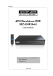
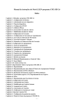
Summary
DVR series are designed to meet the demands for full 4/8/16-channel real-time recording
systems. Frame rate, video quality, and resolution can be adjusted for each channel to meet
recording requirement. VGA engines are built-in 3D intellectual motion adoptive refinement
with vivid image enhancement algorithm to provide best video quality.
DVR series provide various backup features include USB DVD/RW, USB flash disk, HTTP
download, and Backup Manager FTP for multiple DVRs’ files download. Mobile phone device
remote monitoring is also supported. Browser based remote live monitoring and video
playback features are provided.
The DVR can provide D1 real-time for 4-channel and CIF real-time for 8-/16-channel recording
and playback. Full features web-based user interface, multiple DVR system monitoring
features, various backup features, and easy of cabling, the DVR is ideal solution for DVR
applications.
Major Features
Full D1 real-time for 4-ch and CIF real-time for 8-/16-channel H.264 recording and
playback
VGA outputs at 1920 * 1080i, built-in 3D intellectual motion adoptive refinement and vivid
image enhancement engines
Concurrent multiple-channel playback for 4/8/16-channel.
Audio recording and playback
Full features of remote controller controlling
HTTP web-based interface including DVR configuration, PTZ control, playback, and live
monitoring.
3G mobile phone solutions provided.
Resolution, frame rate, and video quality configurable for each channel.
LCD Power saving design.
Trademarks and registered trademarks
Microsoft, Windows 2000, Windows XP, Internet Explorer are registered trademarks of
Microsoft Corporation in the U.S. and/or other countries.
Adobe and Adobe PDF are registered trademarks of Adobe Systems Incorporated in the U.S.
and/or other countries.
JavaScript and all Java-based trademarks and logos are trademarks or registered trademarks
of Sun Microsystems, Inc. in the U.S. and/or other countries.
Linux, Macintosh, Mozilla, and Netscape Navigator are registered trademarks of the respective
holders.
Pelco is a trademark of Pelco - Clovis, CA, and may be registered in certain jurisdictions.
Other names of companies and their products mentioned in this manual may be trademarks or
registered trademarks of their respective owners.
Caution
•
Do not drop or strike this equipment
•
•
Do not install the equipment near any naked flames or heat sources
Do not expose this unit to rain, moisture, smoke or dust environment
•
Do not cover the opening of the cabinet with cloth and plastic or to install this unit
•
in poor ventilated places. Allow 10cm between this unit and its surroundings
Do not continue to operate the unit under abnormal conditions such as detection
of smoke, strange smell or no display on screen while power is turned on
•
Do not touch the power connection with wet hands
•
•
Do not damage the power cord or leave it under pressure
Do not operate this unit near magnet, speaker system, etc., to avoid unnecessary
magnetic interference
•
Connection cables should be grounded properly
CAUTION
RISK OF EXPLOSION IF BATTERY IS REPLACED
BY AN INCORRECT TYPE.
DISPOSE OF USED BATTERIES ACCORDING
TO THE INSTRUCTIONS
DVR User Manual
1
TABLE OF CONTENTS
CHAPTER 1. SYSTEM OVERVIEWS ..................................................................................... 6
Chapter 1-1. Front Panel ................................................................................................... 6
Chapter 1-2. Rear View ..................................................................................................... 9
Chapter 1-3. System LED Status Panel .......................................................................... 10
Chapter 1-4. Remote controller ........................................................................................11
Chapter 1-5. Mouse System............................................................................................ 12
Chapter 1-5-1. Mouse Menu ..................................................................................... 12
Chapter 1-6. Active Camera ............................................................................................ 12
Chapter 1-7. Symbols & Icons......................................................................................... 13
CHAPTER 2. DVR OPERATIONS......................................................................................... 14
Chapter 2-1. Sequential Display...................................................................................... 14
Chapter 2-2. Freeze ........................................................................................................ 14
Chapter 2-3. ROI & PIP Mode ......................................................................................... 14
Chapter 2-4. CH+ & CH- ................................................................................................. 15
Chapter 2-5. Audio & Mute .............................................................................................. 15
Chapter 2-6. Addressable DVR Control Button ............................................................... 15
Chapter 2-7. OK/Cancel Button....................................................................................... 15
CHAPTER 3. PTZ CONTROL ............................................................................................... 16
Chapter 3-1. Instant PTZ Controllable Mode................................................................... 16
Chapter 3-2. Remote Controller & PTZ ........................................................................... 16
Chapter 3-3. Recall Presets ............................................................................................ 16
CHAPTER 4. RECORDING ................................................................................................... 17
Chapter 4-1. Start Recording........................................................................................... 17
Chapter 4-2. Manual Recording ...................................................................................... 17
Chapter 4-3. Schedule Recording ................................................................................... 17
Chapter 4-4. Alarm Switch Activation Recording ............................................................. 17
Chapter 4-5. Motion Detection Recording ....................................................................... 17
CHAPTER 5. PLAYBACK...................................................................................................... 18
Chapter 5-1. Time Search ............................................................................................... 18
Chapter 5-2. Event Search .............................................................................................. 18
Chapter 5-3. REC Search................................................................................................ 19
Chapter 5-4. Time Search ............................................................................................... 19
Chapter 5-5. Other Playback Features............................................................................ 19
CHAPTER 6. MENU SYSTEM .............................................................................................. 21
Chapter 6-1. Setup Menu ................................................................................................ 21
DVR User Manual
2
Chapter 6-2. Camera Setup ............................................................................................ 21
Chapter 6-2-1. Camera Name .................................................................................. 21
Chapter 6-2-2. Camera Disable (Secured Recording Channel) ............................... 22
Chapter 6-2-3. Video Setup ...................................................................................... 22
Chapter 6-3. Monitor Setup ............................................................................................. 22
Chapter 6-3-1. Video Advance ................................................................................... 23
Chapter 6-3-2. Output Resolution .............................................................................. 24
Chapter 6-3-3. Backlight Saving ................................................................................ 24
Chapter 6-3-4. Monitor Standby Mode ....................................................................... 24
Chapter 6-3-5. Monitor Standby Time ........................................................................ 24
Chapter 6-3-6. Main Alarm Switching ........................................................................ 24
Chapter 6-3-7. Main Monitor SEQ Time ................................................................... 24
Chapter 6-3-8. Spot Monitor Switching ...................................................................... 24
Chapter 6-3-9. Spot Sequence Time.......................................................................... 25
Chapter 6-4. Record Setup.............................................................................................. 25
Chapter 6-4-1. Record Quality .................................................................................. 25
Chapter 6-4-2. Frame Rate ....................................................................................... 25
Chapter 6-4-3. Recording Mode ............................................................................... 25
Chapter 6-4-4. Audio................................................................................................. 25
Chapter 6-4-5. Post-alarm Recording ....................................................................... 26
Chapter 6-4-6. Resolution ......................................................................................... 26
Chapter 6-4-7. Schedule ........................................................................................... 26
Chapter 6-4-8. HDD Overwritten............................................................................... 26
Chapter 6-4-9. Limited Recording ............................................................................. 26
Chapter 6-5. Alarm Setup................................................................................................ 26
Chapter 6-5-1. Alarm Input Type .............................................................................. 27
Chapter 6-5-2. Motion Enable ................................................................................... 27
Chapter 6-5-3. Sensitivity.......................................................................................... 27
Chapter 6-5-4. Motion Area Set ................................................................................ 27
Chapter 6-5-5. Alarm Time ....................................................................................... 28
Chapter 6-5-6. SMTP Setup ..................................................................................... 28
Chapter 6-5-7. Buzzer Enable .................................................................................. 28
Chapter 6-5-8. Button Sound .................................................................................... 28
Chapter 6-6. System Setup ............................................................................................. 28
Chapter 6-6-1. Date/Time ......................................................................................... 28
Chapter 6-6-2. HDD Information ............................................................................... 29
Chapter 6-6-3. Password/Access ............................................................................. 30
DVR User Manual
3
Chapter 6-6-4. LOG View ......................................................................................... 31
Chapter 6-6-5. Factory Reset ................................................................................... 31
Chapter 6-6-6. DVR ID.............................................................................................. 31
Chapter 6-6-7. Video System.................................................................................... 31
Chapter 6-6-8. Firmware Update .............................................................................. 31
Chapter 6-6-9. Language .......................................................................................... 32
Chapter 6-6-10. Live Audio ....................................................................................... 32
Chapter 6-7. Network ...................................................................................................... 32
Chapter 6-7-1. IP Mode ............................................................................................ 33
Chapter 6-7-2. HTTP & Video Port Numbers............................................................ 33
Chapter 6-7-3. FTP .................................................................................................... 33
Chapter 6-7-4. DDNS................................................................................................ 33
Chapter 6-7-5. PPPOE Setup .................................................................................... 34
Chapter 6-7-6. MAC .................................................................................................. 34
Chapter 6-8. PTZ Setup .................................................................................................. 34
Chapter 6-8-1. PTZ Transport.................................................................................... 34
Chapter 6-8-2. PTZ Model & Baud Rate ................................................................... 34
Chapter 6-8-3. Preset Setup ..................................................................................... 35
Chapter 6-8-4. Preset ............................................................................................... 35
Chapter 6-8-5. Dwell ................................................................................................. 35
Chapter 6-8-6. Speed ............................................................................................... 35
Chapter 6-8-7. Position ............................................................................................. 35
Chapter 6-8-8. IRIS & Auto IRIS ............................................................................... 36
Chapter 6-8-9. Focus & Auto Focus ......................................................................... 36
Chapter 6-8-10. Save Presets .................................................................................. 36
Chapter 6-8-11. Clear All Preset ............................................................................... 36
Chapter 6-8-12. Direct Keyboard Access .................................................................. 36
Chapter 6-9. Backup........................................................................................................ 36
Chapter 6-9-1. FTP Download .................................................................................. 37
Chapter 6-9-2. HTTP File Download......................................................................... 37
CHAPTER 7. FILE PLAYBACK ............................................................................................. 38
Chapter 7-1. Play H.264 Files ......................................................................................... 38
Chapter 7-2. Play H.264 Audio........................................................................................ 38
Chapter 7-3. Manage DVRs Download ........................................................................... 39
Chapter 7-4. Connect to DVR’s FTP Service. ................................................................. 39
Chapter 7-5. Start to Download DVR’s Files. .................................................................. 40
Chapter 7-6. Play local DVR’s files.................................................................................. 40
DVR User Manual
4
CHAPTER 8. NETWORK ...................................................................................................... 41
Chapter 8-1-1. Configuration .................................................................................... 41
Chapter 8-1-2. Internet Ports .................................................................................... 41
Chapter 8-2. Access the DVR via Internet Browser ......................................................... 42
Chapter 8-2-1. Before Using Internet ........................................................................ 42
Chapter 8-2-2. Logon ................................................................................................ 43
Chapter 8-2-3. Hyper Link Panel .............................................................................. 43
Chapter 8-2-4. Playback Over Network .................................................................... 43
Chapter 8-2-5. Save JPEG file.................................................................................. 44
Chapter 8-2-6. Network Audio .................................................................................. 45
Chapter 8-3. Configure the DVR via Web page .............................................................. 45
Chapter 8-3-1. Camera Setting .................................................................................. 45
Chapter 8-3-2. Recording Setting .............................................................................. 45
Chapter 8-3-3. Recording Schedule Table ................................................................ 46
Chapter 8-3-4. Alarm Setting ..................................................................................... 46
Chapter 8-3-5. Alarm E-mail ...................................................................................... 46
Chapter 8-3-6. Network Setting ................................................................................. 47
Chapter 8-3-7. System Setting................................................................................... 47
Chapter 8-3-7-1. Timer ........................................................................................ 47
Chapter 8-3-7-2. User Setting ............................................................................. 48
Chapter 8-3-7-3. System Status .......................................................................... 49
Chapter 8-3-7-4. Firmware update ...................................................................... 50
APPENDIX.............................................................................................................................. 51
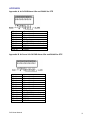
Appendix A. 4-Ch DVR Alarm I/Os and RS485 for PTZ ................................................... 51
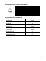
Appendix B. 8-Ch and 16-CH DVR Alarm I/Os and RS485 for PTZ................................. 51
Appendix C. RS485 Input and Output Pin Assignment .................................................... 52
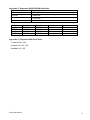
Appendix D. Hard Disk Drive Support List........................................................................ 52
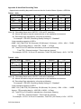
Appendix E. Supported USB-DVD/RW and Disks............................................................ 53
Appendix F. Supported USB Flash Disk ........................................................................... 53
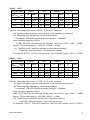
Appendix G. Hard Disk Recording Table .......................................................................... 54
Specification............................................................................................................................ 56
DVR User Manual
5
CHAPTER 1. SYSTEM OVERVIEWS
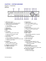
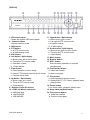
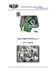
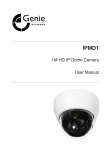
Chapter 1-1. Front Panel
[DVR304]
1. LED status panel
Please see system LED status panel.
2. Split-display/camera buttons
a. 4 split-display
b. Camera selection mode
3. SEQ button
4. EJECT button
5. ESC
6. Left button
a. Move cursor left at menu setup.
b. Pan left at PTZ control mode.
c. Decrease a value.
7. Enter button
a. Enter operation in menu setup.
b. Instant PTZ camera selection at live mode.
c. Camera active mode
8. Up button
a. Move cursor up in menu.
b. Tilt up at PTZ control mode.
9. Remote control IR receiver
10. USB 2.0 connector
a. USB flash disk
b. USB DVD/RW
DVR User Manual
11. Right button
a. Move cursor right in menu.
b. Pan right at PTZ control mode.
c. Increase a value.
12. Down button
a. Move cursor down at menu mode.
b. Tilt down at PTZ control mode.
13. Menu button
14. Backup button
15. REC button
Start recording operation or stop the
recording task.
16. Fast forward button
a. Video fast forward
b. Next event page
17. Play button
a. Invoke playback selection menu.
b. Replay after FF, FR, Pause, stepping
when playing video.
18. Pause button
19. Stop video playback button
Live: freeze video, playback: pause video
20. Fast reverse button
a. Video fast reverse
b. Previous event page
6
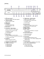
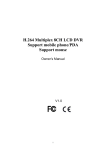
[DVR308]
1. LED status panel
Please see system LED status panel.
2. Camera buttons
Camera selection mode
3. SEQ button
4. PTZ button
a. At PTZ control mode
b. At Split-display mode
5. ESC button
6. Left button / Split-display
a. Move cursor left at menu setup.
b. Pan left at PTZ control mode.
c. Decrease a value.
d. 4 split-display
7. Enter button
a. Enter operation in menu setup.
b. Instant PTZ camera selection at live mode.
c. Camera active mode
8. Up button
a. Move cursor up in menu.
b. Tilt up at PTZ control mode.
9. Remote control IR receiver
10. USB 2.0 connector
a. USB flash disk
b. USB DVD/RW
c. USB MOUSE
DVR User Manual
11. Right button / Split-display
a. Move cursor right in menu.
b. Pan right at PTZ control mode.
c. Increase a value.
d. 9 split-display
12. Down button
a. Move cursor down at menu mode.
b. Tilt down at PTZ control mode.
13. Menu button
14. Backup button
15. REC button
Start recording operation or stop the
recording task.
16. Fast forward button
a. Video fast forward
b. Next event page
17. Play button
a. Invoke playback selection menu.
b. Replay after FF, FR, Pause, stepping when
playing video.
18. Pause button
Live: freeze video, playback: pause video
19. Stop video playback button
20. Fast reverse button
a. Video fast reverse
b. Previous event page
7
[DVR316]
1. LED status panel
Please see system LED status panel.
2. Camera buttons
Camera selection mode
3. SEQ button
4. PTZ button
a. At PTZ control mode
b. At Split-display mode
5. ESC button
11. Right button / Split-display
a. Move cursor right in menu.
b. Pan right at PTZ control mode.
c. Increase a value.
d. 16 split-display
12. Down button / Split-display
a. Move cursor down at menu mode.
b. Tilt down at PTZ control mode.
c. 4 split-display
6. Left button / Split-display
13. Menu button
a. Move cursor left at menu setup.
14. Backup button
b. Pan left at PTZ control mode.
15. REC button
c. Decrease a value.
Start recording operation or stop the
d. 13 split-display
recording task.
7. Enter button
16. Fast forward button
a. Enter operation in menu setup.
a. Video fast forward
b. Instant PTZ camera selection at live mode.
b. Next event page
c. Camera active mode
17. Play button
8. Up button / Split-display
a. Invoke playback selection menu.
a. Move cursor up in menu.
b. Replay after FF, FR, Pause, stepping when
b. Tilt up at PTZ control mode.
playing video.
c. 9 split-display
18. Pause button
9. Remote control IR receiver
Live: freeze video, playback: pause video
10. USB 2.0 & Mouse connector
19. Stop video playback button
a. USB flash disk
20. Fast reverse button
b. USB DVD/RW
a. Video fast reverse
c. USB MOUSE
b. Previous event page
DVR User Manual
8
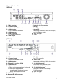
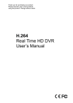
Chapter 1-2. Rear View
[DVR304]
1. Main monitor
2. Camera inputs
Analog camera BNC inputs
3. Audio inputs
Four RCA audio connectors
4. Audio output
5. USB connector
For mouse connection
6. VGA output
7. Network RJ-45 connector
8. RS-485
For PTZ connection
9. Alarm I/Os
Alarm input switches, 1 N/O alarm output,
and 1 N/C alarm output
10. DC 12V input
11. Fan
[DVR308]
1. Main monitor
2. Camera inputs
Analog camera BNC inputs
3. Audio inputs
Four RCA audio connectors
4. External IR receiver (RCA)
5. Audio output
6. Spot monitor
a. Spot monitor accessible by keyboard.
b. Each spot output can be
programmable for alarmed camera
display and sequence display.
7. VGA output
8. Network RJ-45 connector
DVR User Manual
9. RS-485
For PTZ connection
10. Alarm I/Os
Alarm input switches, 1 N/O alarm output,
and 1 N/C alarm output
11. RJ-45 Keyboard-in
Connected from previous DVR’s
keyboard output in daisy chain.
12. RJ-45 Keyboard-out
Connect to the next DVR’s input.
RJ-45 connector
13. DC 12V input
15. Power switch
9
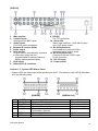
[DVR316]
1. Main monitor
2. Camera inputs
Analog camera BNC inputs
3. Audio inputs
Four RCA audio connectors
4. External IR receiver (RCA)
5. Audio output
6. Spot monitor
a. Spot monitor accessible by keyboard.
b. Each spot output can be
programmable for alarmed camera
display and sequence display.
7. VGA output
8. Network RJ-45 connector
9. RS-485
For PTZ connection
10. Alarm I/Os
Alarm input switches, 1 N/O alarm output,
and 1 N/C alarm output
11. RJ-45 Keyboard-in
Connected from previous DVR’s
keyboard output in daisy chain.
12. RJ-45 Keyboard-out
Connect to the next DVR’s input.
RJ-45 connector
13. DC 12V input
15. Power switch
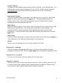
Chapter 1-3. System LED Status Panel
System LEDs are meaningful while operating the DVR. The status of each LED is described
as in the following table:
[DVR304]
Item
1
2
3
4
5
6
LED
BACKUP
POWER
HDD
ALARM
REC
NET
DVR User Manual
[DVR308/316]
Description
Backup LED indicator
DVR power on/off indicator
Master HDD recording indicator
External alarm switches indicators when
motioned or alarmed
Recording indicator
Network indicator
Color
Green (blinking)
Yellow
Green (blinking)
Red
Yellow
Green
10
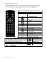
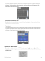
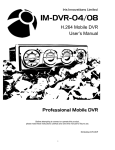
Chapter 1-4. Remote controller
The button arrangement of the remote controller is designed for easy-to-use purposes.
Buttons are separated in regions based on their features including DVR operational keys,
pan, tilt, and zoom camera device (PTZ) keys, numerical keys, and PTZ buttons.
DVR operational keys
MENU
ESC
ZOOM
REC
FREEZE
Setup menu
Escape/exit/stop buzzer
Digital video 5X or 9X zooming
Record/stop recording
Live video freeze
Pause
Playback
Stop
Fast forward
Fast rewind
CH+
Next single channel
CH-
Previous single channel
4 split display
9 split display
16 split display
SEQ
AUDIO
BACKUP
DVR
Sequential display
Audio/mute
Video backup
Addressable DVR control
Auto Pan
Perform auto pan feature
Move up/tilt up
Zoom in
Zoom in of a fast dome camera
Move down/tilt down
Zoom out
Zoom out of a fast dome camera
Move left/pan left
Preset
Call preset of a fast dome camera
Move right/pan right
Enter/set
0 to 9
Numerical keys
DVR User Manual
11
Chapter 1-5. Mouse System
The DVR has both USB mouse interface. General mouse operations are described as
below:
Left mouse click/
Right mouse click
Left mouse double click/
mouse drag
Mouse scroll
Left mouse click—In mouse menu system, mouse click can select a menu item. In windowdivision mode, click on a camera that is to select the camera in activation mode (active camera).
Left mouse double click-- In window division mode, click on a camera that can call the
camera in full screen mode.
Mouse drag—In motion area setup mode, mouse drag can setup a motion area.
Mouse scroll—In setup menu, mouse scroll can increase or decrease a value.
Right mouse click—Popup a submenu system or return to live in main menu.
Chapter 1-5-1. Mouse Menu
For using mouse menu, please use the mouse click on Menu item. The mouse menu shows
on the screen for more system features.
SETUP
PLAYBACK
ZOOM
PTZ
AUDIO ON/OFF
SHUTDOWN
Chapter 1-6. Active Camera
Active camera is shown as checked at camera name/number. Once a camera is activated,
the camera can be controlled for PTZ operation or for camera audio. Moving the active
camera sequentially, one can simply press the Enter button on the remote controller, the
keypad, or keyboard(s).
DVR User Manual
12
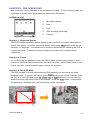
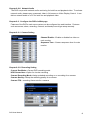
Chapter 1-7. Symbols & Icons
The DVR adopts symbols and icons for graphical user interface (GUI) design. These
symbols and icons contain useful information in operating the DVR. All the symbols and
icons are discussed in the rest of the chapter.
Task bar
The task bar shows up on bottom of the main monitor for indicating the operation status of
the DVR while operating the remote controller, the mouse, the keypad, or a keyboard.
The icons of the DVR are described in the follow table:
Mouse menu
Controlled DVR ID/RS-485 ID
The DVR’s ID/RS-485 ID address
Manual recording mode
Schedule recording mode
Zoom mode
Sequence mode
DVR User Manual
13
CHAPTER 2. DVR OPERATIONS
Most of the time, DVR is operated at the surveillance/live mode. In live monitoring mode, the
information of screen layout and symbols are described in this section.
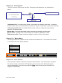
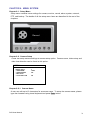
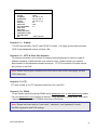
SCREEN LAYOUT
REC 2007/06/22 11:03:50
1
2
3
HDD 9%
4
5
①
Recording indicator
②
Date
③
Time
④
HDD recording percentage
⑤
Task bar
Chapter 2-1. Sequential Display
The DVR provides multiplexer feature displaying each camera in full screen sequentially in
specific time period. To perform sequential display, simply press SEQ button on the remote
controller or a keyboard. The sequence icon shows on the task bar for indicating the DVR is
in sequence status. To perform sequence using mouse, please click on Mouse Menu>Sequence.
Chapter 2-2. Freeze
In live monitoring and playback modes, the DVR provides screen-freezing feature in which
suspicious individuals can be determined. To freeze the screen, press Freeze button on the
remote controller. Press the button again to cancel this operation.
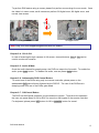
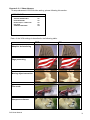
Chapter 2-3. ROI & PIP Mode
The DVR provides 5X and 9X digital zooming (ROI) capability live monitoring and video
playback modes. To perform this feature, press Zoom button on the remote controller. Once
the DVR is in zooming status, press Up, Down, Left, or Right buttons to move the zooming
window around to view other portion of the channel. Press the Zoom button. It can perform
5X digital zoom, 9X digital zoom, and normal view screen in sequence.
DVR User Manual
14
To perform ROI feature using a mouse, please first perform mouse drag for zoom mode. Once
the video is in zoom mode, scroll mouse can perform 5X digital zoom, 9X digital zoom, and
normal view screen.
5X digital zoom
9X digital zoom
Note: Only 4-Ch DVR supports digital zoom with PIP feature.
Chapter 2-4. CH+ & CHIn case of scanning through cameras in full screen, channel buttons, CH+ & CH- can be
used to monitor all cameras.
Chapter 2-5. Audio & Mute
Once the audio channel is properly setup, the DVR can output the live audio. To enable live
audio, press Audio button. To disable live audio, one can press Audio button.
Chapter 2-6. Addressable DVR Control Button
To control one of the DVRs using only one remote controller, please press on the
addressable DVR control button followed by the DVR ID. The rest of the DVRs are in
sleeping mode until one of the DVRs gets called.
Chapter 2-7. OK/Cancel Button
The DVR has OK/Cancel operation in menu/submenu system. To perform this operation,
the user can press Menu for OK or ESC for cancel on the keypad or the remote controller.
For keyboard, please press SET button for OK or CANCEL button for cancel.
DVR User Manual
15
CHAPTER 3. PTZ CONTROL
PTZ device can be controlled in live monitoring mode and PTZ setup mode via the keypad
and/or the remote controller. The rest of the chapter describes the ways of controlling PTZ
devices using the keypad and a remove controller.
Chapter 3-1. Instant PTZ Controllable Mode
Instantly controllable PTZ camera (active camera) is shown in yellow color in live monitoring
mode indicating that the camera can be instantly controlled for PTZ operations. Moving the
active camera sequentially, one can simply press the Enter button on the remote controller.
Once a camera is in active mode (text in yellow), major PTZ features can be easily
performed.
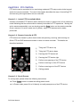
Chapter 3-2. Remote Controller & PTZ
PTZ buttons are framed in yellow that contain auto panning, zooming, and zooming out.
Other PTZ and DVR buttons are shown in blue on remote controller. The details are
described as below:
①
Tilting the PTZ device up
6
②
Tilting the PTZ device down
7
③
Panning the PTZ device left
④
Panning the PTZ device right
⑤
Perform auto panning of the PTZ device
⑥
Perform zooming in of the PTZ device
⑦
Perform zooming out of the PTZ device
⑧
Calling presets
1
5
3
4
8
2
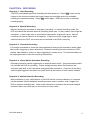
Chapter 3-3. Recall Presets
To call a preset, please follow the following instructions:
Press Preset button to enable the calling preset mode.
In Preset mode, preset 01 to 64 directly to recall preset points of the PTZ device.
DVR User Manual
16
CHAPTER 4. RECORDING
Chapter 4-1. Start Recording
The DVR automatically performs recording task after power on. Press REC button on the
keypad or the remote controller that it can change the recording mode from schedule
recording to manual recording. Press REC button again. DVR returns back to schedule
recording again.
Chapter 4-2. Manual Recording
Manual recording is equivalent to emergency recording. In manual recording mode, the
DVR records all the cameras based on recording frame rate. In many cases, there might be
a situation. A user might want to record all the cameras for suspicious events. Manual
recording can now be used for an emergency. If there are motion triggerings or alarm
switches set for the DVR, the events can be recorded in the DVR’s event log.
Chapter 4-3. Schedule Recording
For storage consideration, there are many applications that may be required to record video
after motion triggering or alarm activations. Schedule recording can be used that the DVR
records video based on motion or alarm triggering for certain hours. The schedule table can
be preprogrammed to meet the recording requirement.
Chapter 4-4. Alarm Switch Activation Recording
Recording operation can be triggered by an external alarm switch. An external alarm switch
can activate the DVR for recording. Proper settings such as Alarm Rec Duration and
activation type (N/O or N/C) should be configured before operation. Once one of the alarm
switches gets triggered, the alarm icon (bell) shows at the bottom of each camera channel.
Chapter 4-5. Motion Detection Recording
Motion detection is very useful feature of the DVR that the intrusion detection of a camera
can be detected. Motion detection recording sensors motion variation, and it triggers the
DVR to perform recording task. Once motion detection is activated, the motioned channel
shows an alarm icon (little man) on the screen to inform users.
DVR User Manual
17
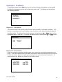
CHAPTER 5. PLAYBACK
To playback, please press Play button on the remote controller, a keyboard, or the keypad.
A playback message box shows up for searching video clips. The details are described in
the following sections:
PLAYBACK
TIME SEARCH
EVENT SEARCH
RECORD SEARCH
DATE SEARCH
Chapter 5-1. Time Search
Time search feature can perform date and time search based on recorded video data. This
feature is very easy-to-use, and it allows a user to perform video searching task throughout
hard disk drives. To perform time search operation, simply press Left or Right button on the
highlighted date or time field. To change the date and time, please press Up or Down button.
TIME SEARCH
DATE
TIME
2007/09/11
19/54/00
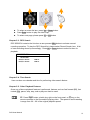
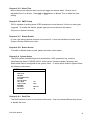
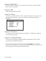
Chapter 5-2. Event Search
Event list contains information including date, time, event type, and camera channel for the
event. There are external alarm event and motion alarm event that can be found in event list.
To filter out events, please set starting and ending time in the event search dialog box. To
view operation log, please see System->Log View for detail.
EVENT SEARCH
RECORD TIME
05/07/04 13:40:48
05/07/04 13:40:42
05/07/04 13:40:35
DVR User Manual
EVENT
ALARM CH01
ALARM CH01
ALARM CH01
18
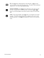
To select an event list item, press Up or Down button.
Press Enter button to play the video clips
To select next page, please press FF or FR button
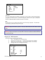
Chapter 5-3. REC Search
REC SEARCH contains the list when a user presses REC button to activate manual
recording operation. To play the REC Search list, please select Record Search item. A list
of start recording shows up accordingly. Press Up or Down button to select list item for
playback.
RECORD SEARCH
RECORD TIME
2007/07/04 13:39:47
2007/07/04 13:38:42
MANUAL
MANUAL
Chapter 5-4. Time Search
User can also use calendar and time for performing video search feature.
Chapter 5-5. Other Playback Features
Once one of above playback features is performed, features such as fast forward (FF), fast
rewind (FR), pause, stop, step, and re-play can then be used.
FF: Press Right button, shuttle ring right on the front panel, or FF key on the
remote controller to fast forward the playing video. The speed of fast forwarding
is range from 2X ~ 6X of the original playback speed.
DVR User Manual
19
FR: Press Left button, shuttle right left on the front panel, or FR key on the
remote controller to fast rewind the playing video. The speed of fast rewinding is
range from 2X ~ 6X of the original playback speed.
PAUSE & STEPPING: press Pause button while playing video that can pause
the video. Once the video is in pausing mode, one can press Left or Right
button on the DVR’s keypad or the remote controller to play the video step-bystep.
STOP: To stop video playback, press Stop button on the keypad or the remote
controller. The DVR’s screen switches back to playback main menu for other
playback operations. Press ESC button again that it returns to live monitoring
mode.
DVR User Manual
20
CHAPTER 6. MENU SYSTEM
Chapter 6-1. Setup Menu
Setup menu contains menu settings for camera, monitor, record, alarm, system, network,
PTZ, and backup. The details of all the setup menu items are described in the rest of the
chapters.
Record
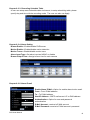
Chapter 6-2. Camera Setup
A user can setup camera settings at camera setup option. Camera name, video setup, and
video loss detection can be found at this option.
CAMERA
CAMERA SELECT
CAMERA NAME
CAMERA DISABLE
VIDEO SETUP
V.LOSS DETECTION
1
CAM01
OFF
ON
Chapter 6-2-1. Camera Name
A user can edit up to 12 characters for a camera name. To setup the camera name, please
type the character using visual keyboard and press Enter button.
DVR User Manual
21
Visual Keyboard
INSERT: CAMERA
1
Q
A
Z
2
W
S
X
3
E
D
C
4
R
F
V
5
T
G
B
6
Y
H
N
7
U
J
M
8
I
K
<
9
O
L
>
0
P
:
/
{
‘
=
}
:
SPACE BAR
Back
Cursor
OK
2
Enter
Page
Chapter 6-2-2. Camera Disable (Secured Recording Channel)
Channel enable feature can disable the live video of a camera. The channel can still
perform video recording. For privacy or security considerations, irrelevant people may be
prohibited to see the live video.
Chapter 6-2-3. Video Setup
Video setup can adjust video’s contrast, brightness, hue, and saturation for each camera. To
restore the default setting, please press Load Default menu item.
VIDEO SETUP
CONTRAST
BRIGHTNESS
HUE
SATURATION
LOAD DEFAULT
50
50
50
50
Chapter 6-2-4. Video Loss Detection
To enable or disable video loss detection, please set this option to be On or OFF. If the
video signal is unstable and causes video loss, a user can disable this option. Unstable
video signal may generate thousand of video loss events in one second. Temporarily
turn this option Off that can improve DVR system performance.
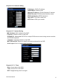
Chapter 6-3. Monitor Setup
MONITOR
VIDEO ADVANCE
OUTPUT RESOLUTION
BACKLIGHT SAVING
MONITOR STAND BY MODE
MONITOR STAND BY TIME
MAIN ALARM SWITCH
MAIN MONITOR SEQ TIME
SPOT ALARM SWITCH
SPOT/QUAD SEQ TIME
DVR User Manual
SXGA
OFF
OFF
OFF
OFF
OFF
22
Chapter 6-3-1. Video Advance
To setup advanced LCD/VGA video setting, please following this section.
VIDEO ADVANCE
ADAPTIVE DEINTERLANCE
EDGE PRESERVING
ON
ON
MOVING OBJECT CORRECTION
FILE MODE
SHARPNESS ENHANCER
ON
ON
OFF
Each of the VGA settings is described in the following table:
OFF
ON
Adaptive de-interlacing
Edge preserving
Moving object correction
Film mode
Sharpness enhancer
DVR User Manual
23
Chapter 6-3-2. Output Resolution
VGA output resolutions can be set at this option.
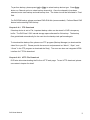
Chapter 6-3-3. Backlight Saving
DVR/NVR is 24 hours non-stop running. LCD panel consumes the most energy to a typical
PC. The following figure shows LCD panel consumption rate.
Backlight saving mode is to turn the LCD backlight darker. Turn backlight of the LCD can
also save LCD power consumption.
Chapter 6-3-4. Monitor Standby Mode
After stand by time of the main monitor, LCD monitor is in sleep mode to save power
consumption. To reactivate the LCD monitor, please enable alarm/motion detection, move
DVR’s mouse, press any key on the front panel, or press any key on the remote control.
Chapter 6-3-5. Monitor Standby Time
To setup standby time, please change the time at this feature.
Chapter 6-3-6. Main Alarm Switching
The main monitor output can be configured in displaying camera’s full screen. To enable
this feature, please select the camera in camera selection box.
Chapter 6-3-7. Main Monitor SEQ Time
Sequence feature can multiplex each camera screen in full size in specific time
period. Once the sequence time is set, press SEQ button on the remote controller
or the keypad to activate the sequence feature.
Chapter 6-3-8. Spot Monitor Switching
The DVR has a spot output. To setup the sequence, please first assign spot or quad output.
Specify SEQ TIME in seconds. Once above has been setup, spot monitor starts to perform
sequence display.
DVR User Manual
24
Chapter 6-3-9. Spot Sequence Time
To specify Spot sequence time, please set this option.
Note: Spot monitor is for 8/16-Chananel only.
Chapter 6-4. Record Setup
Record setup menu can setup features related to recording features such as recording
quality, frame rate, recording mode, audio selection, alarm recording, recording resolution,
group of pictures (GOP), schedule table, HDD overwritten, and limited recording.
RECORD
CAMERA SELECT
QUALITY
FRAME RATE
RECORD MODE
AUDIO
POSTALARM
RESOLUTION
GOP
SCHEDULE TABLE
HDD OVERWRITTEN
LIMITED RECORDING
1
HIGH
30
SCHDEDULE
1
5 SEC
CIF
4
YES
Chapter 6-4-1. Record Quality
The recording quality can be configured for each channel. To change the quality setting,
press Left or Right button.
Chapter 6-4-2. Frame Rate
Each camera channel can be setup for its frame rate individually. To setup the frame rate,
please press the Enter button and using the Left or Right button for the adjustment.
Chapter 6-4-3. Recording Mode
Each camera can be setup for schedule recording or no recording. Once the recording
mode has been turned off, each recording mode including alarm, motion, or manual
recording does not record.
Chapter 6-4-4. Audio
There are up to four audio inputs that can be recorded into the DVR. To setup audio
recording, please assign the audio channel to a particular camera.
DVR User Manual
25
Chapter 6-4-5. Post-alarm Recording
Post-alarm recording can record the video of a camera after a particular alarm/motion is
triggered. To enable post-alarm recording, please set the post-alarm recording seconds for
this option.
Chapter 6-4-6. Resolution
The DVR can provide full D1 or CIF recording solutions. The default setting is at full D1
recording. To change recording resolution, please press Left or Right button.
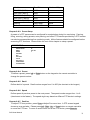
Chapter 6-4-7. Schedule
Once the schedule has been setup, the DVR can record camera video based on the
schedule table. The DVR’s timer detects every second to check if it should start to record.
To edit the schedule table, a user can press Enter button for editing mode. Press Enter
button that can change recording mode, always, sensor, motion, or no record. For the Apply
All setting, the user can use Up or Down button to select Apply All menu item. Press Enter
button on” Apply All” menu item that can setup a recording mode for a week.
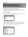
SCHEDULE
0 4 8 10 12 14 16 18 20 22 24
MON
TUE
WED
THU
FRI
SAT
SUN
□ ALWAYS
□
SENSOR
MOTION
□
□
NONE RECORDING
Chapter 6-4-8. HDD Overwritten
The DVR can be setup for HDD circular recording. If the user does not want the HDD to be
overwritten, please turn the option to be off.
Chapter 6-4-9. Limited Recording
In many countries, the HDD recording may be limited and can be only accessed for a certain
period. Once the recorded data passes the period, the data can no longer be accessed.
Chapter 6-5. Alarm Setup
Alarm setup menu allows changing the settings of extern alarm switches, motion alarm,
buzzer, and alarm recording duration. To change these settings, please enter Alarm setup
menu and follow the instructions:
DVR User Manual
26
ALARM
CAMERA SELECT
ALARM INPUT TYPE
ALARM ENABLE
MOTION SENSITIVITY
MOTION AREA SET
MOTION BUZZER TIME
ALARM TIME
BUZZER
BUTTON SOUND
CH01
OFF
OFF
OFF
NORMAL
05 SEC
05 SEC
ON
ON
Chapter 6-5-1. Alarm Input Type
The DVRs’ alarm inputs can be configured as normal open (N/O) or normal close (N/C). The
alarm input is one-to-one mapped to a camera respectively.
Chapter 6-5-2. Motion Enable
Motion Enable enables motion alarm activation, if the motion area has been set with proper
motion sensitivity. Press Left or Right button at Motion Enable menu item to change the setting.
Chapter 6-5-3. Sensitivity
There are eight levels of sensitivity adjustable for motion alarm triggering, range from Very
High to Very Low. Press Left or Right button to change the sensitivity setting.
Chapter 6-5-4. Motion Area Set
There are few ways to setup motion area. The detail setup sequence is described as follows:
Step 1
Step 2
Keypad
Keyboard
Remote controller
Enter Motion Area Set menu item.
Press Up, Down, Left, or Right to move cursor
Step 3
Step 4
Step 5
Press Enter to define starting area.
Press Enter again to finish a motion detection zone.
To clear motion zones press Menu button
Step 6
Press ESC for exit the setting menu.
DVR User Manual
Mouse
Move mouse for starting
position.
Mouse-drag for an area.
Double-click for clear
motion zones.
Right-mouse click for exit
motion zone setting.
27
Chapter 6-5-5. Alarm Time
Motion alarms and external alarm inputs can trigger the buzzer alarm. Buzzer time is
adjustable from 0 to 99 sec. Press Left or Right button on Buzzer Time to adjust the time
setting.
Chapter 6-5-6. SMTP Setup
DVR is capable of sending alarm JPEG snapshots to email account if motion or alarm gets
triggered. To enable this feature, please type in the email account information.
(Only limit to intranet network)
Chapter 6-5-7. Buzzer Enable
In case, the warning buzzer requires to be turned off. A user can disable the buzzer under
System->Buzzer Enable menu item.
Chapter 6-5-8. Button Sound
To enable or disable button sound, please set button sound option.
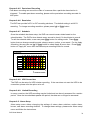
Chapter 6-6. System Setup
The DVR system related settings such as date/time, HDD, password, log, restoring
manufacturing default, DVR/RS-485 ID, video system, firmware update, language, and
health check can be configured at this system menu. To setup above features, please follow
the following instructions:
SYSTEM
DATE / TIME
HDD INFO
PASSWORD/ACCESS
LOG VIEW
FACTORY RESET
DVR / 485 ID
VIDEO SYSTEM
FIRMWARE
LANGUAGE
LIVE AUDIO
OFF
NTSC
ENGLISH
ON
Chapter 6-6-1. Date/Time
The DVR has built-in timer to record time information. One can choose different time format
or disable the timer.
DVR User Manual
28
DATE / TIME
TIME
DATE
FORMAT
DISPLAY
TIME SYNC
DST
DISAPLY POS.
18:16:17
2005 / 06 / 30
YYYY / MM / DD
ON
OFF
OFF
0
Time Sync
Time Sync feature allows the DVR to synchronize its timer system to PIH-931D keyboard.
To synchronize DVR’s timers to a PIH-931D keyboard, please set this option to Keyboard.
PIH-931D keyboard starts to synchronize every 15 minutes.
NTP
To use NTP time sync, please select NTP service at Time Sync selection. The DVR will
automatically synchronize with an NTP server.
Warning: Highly recommend to perform Time Sync feature before the DVR starts to record
video.
Warning: Highly recommend to re-format HDD, if the timer has been set and the HDD has
recorded video data.
Chapter 6-6-2. HDD Information
HDD INFO shows the following information:
1.
2.
Size—The capacity of the hard disk drive
Approximate recording hour—recording hours based on the HDD(s)
3.
4.
Approximate recording days—recording days based on the HDD(s)
Average frame size—Average picture size
HDD INFO
PRI
MASTER
SIZE
SLAVE
SIZE
SEC MASTER
SIZE
SLAVE
SIZE
HDD FORMAT
APPROX REC HOURS
APPROX REC DAYS
RESET COUNTER
DVR User Manual
250 GB
250 GB
142
7
29
HDD Format
To format HDDs, please select HDD Format menu item. Password is required for preventing
unauthorized access. A warning message also gets prompted for formatting verification.
Please be alerted to this operation. It may erase not only event list data but also recorded
video data. Press Enter button at HDD Format menu to format the hard disk drives.
Formatting hard disk drives may take several seconds based on the number of lists recorded.
Chapter 6-6-3. Password/Access
The DVR has three sets of password protection (accounts) preventing unauthorized access.
To activate password function, please turn Enable Password on or off at System->Password.
The password consists of four to eight digits for entering the DVR. The default passwords
are admin, “1111”, operator, “2222”, and guest, “3333”. The acceptable characters are 1 to
10 (0) and A to Z. To change the password setting, please press Enter at System>Password->Change Password.
PASSWORD/ACCESS
USER
OLD PASSWORD
NEW PASSWORD
CONFIRM PASSWORD
PROPERTY
ENABLE PASSWORD
ADMIN
****
****
****
OFF
Note: In case, forgetting your password, please contact your sales agent for master
password.
Access Property
Each account can be assigned for access rights including video playback, menu setup, video
backup, PTZ setup, network setup, and remote network playback. For an administrator, she
or he can manage various access rights for other users.
PROPERTY
PLAYBACK
SETUP
BACKUP
PTZ SETUP
NETWORK SETUP
REMOTE PLAYBACK
DVR User Manual
ON
ON
ON
ON
ON
ON
30
Chapter 6-6-4. LOG View
Operational log, video lose event, abnormal power off, and other DVR events can be
reviewed by LOG View menu item.
Chapter 6-6-5. Factory Reset
A user may want to restore manufacturing default settings. A confirm message shows up for
final verification. To perform this task, please select Factory Reset at System->Factory
Reset and press Enter button.
Note: Factory reset does not affect IP address, video system, and language settings.
Chapter 6-6-6. DVR ID
Each DVR can be assigned by a unique DVR ID accessed by the remote controller. With a
unique DVR ID set, the remote controller issues commands to a particular DVR. The rest of
DVRs are in sleep mode.
To operate addressable DVR control feature, please refer to chapter 1 Addressable DVR
Control Button.
Chapter 6-6-7. Video System
The DVR supports both NTSC and PAL video systems. The DVR allows switching from one
video system to another without rebooting. To change video system, press Left or Right
button at System->Video System.
Chapter 6-6-8. Firmware Update
Firmware update allows one to upgrade the DVR’s firmware for improving system
performance. To perform firmware update, press Enter on Setup->System->Firmware
Update. There are two ways to perform firmware update via (1) USB flash disk at DVR site
and (2) HTML interface via network.
To perform firmware update using USB flash disk, please follow the instructions:
(1) Plug in a portable USB disk at the DVR’s USB port.
(2) Press Enter button at Start Update Firmware.
(3) After finishing transferring, remove the USB device and reboot the DVR.
DVR User Manual
31
Prepare Firmware
To prepare firmware update, please create a directory, firmware, in the USB flash disk. The
USB flash disk should contain file system FAT-16 or FAT-32. Please visit the web site at
www.meritlilin.com to download the latest firmware and save the file in the directory
mentioned above.
Start Update Firmware
To perform firmware update, please plug in the USB flash disk into the DVR. Select Start
Update Firmware menu item and press Enter button. It will automatically transfer the
firmware into the DVR. After transferring firmware, wait until “Please Reboot System”
message gets prompted and reboot the DVR.
Export Setup
Export setup feature allows a user to export internal configuration into a system file, at USB
flash disk’s firmware directory. The file can later be imported to other machines. The
imported machine’s internal configuration gets updated based on the original DVR’s
configuration. To perform Export Setup, please select Export Setup menu item and press
Enter button.
Import Setup
To perform Import Setup feature, please select Import Setup menu item and press Enter key.
The configuration of the DVR gets updated based on the system file.
Version
Version menu item indicates the current version number of the DVR.
Chapter 6-6-9. Language
The DVR provides multi-language OSD support. A user can change his/her preferred
language to operate the DVR. Press on Left or Right button to change the Language setting.
Chapter 6-6-10. Live Audio
To turn on or off live audio monitoring, please set Live Audio option.
Chapter 6-7. Network
The DVR allows a user to access the video via Internet or LAN. In order to connect to LAN
or Internet, subnet mask, gateway, and IP address should be configured. Please consult
your Internet provider or system administrator for above information.
DVR User Manual
32
NETWORK
IP MODE
IP ADDRESS
SUBNET MASK
GATWAY
HTTP PORT
VIDEO PORT
FTP PORT NUMBER
DDNS SETUP
SMTP SETUP
MASTER DVR SETUP
SEND TABLE TO MDVR
DVR TABLE SETUP
MAC
STATIC
192 . 168 . 0 . 111
255 . 255 . 255 . 0
192 . 168 . 0 . 111
80
3100
21
00:0F:FC:00:00:03
Chapter 6-7-1. IP Mode
The DVR provide static, DHCP, and PPPoE IP modes. It is highly recommend to access
DVR in high bandwidth network such as LAN.
Chapter 6-7-2. HTTP & Video Port Numbers
For Internet connection, port number IP mapping technologies can be used for single IP
address shared by multiple devices via a network router. Please consult your network
administrator for this advanced network technique. HTTP Port number is the web service
port number of the DVR.
Note: Default Internet port numbers for the DVR are port 80 (HTML web pages) and port
3100 (video port)
Chapter 6-7-3. FTP
FTP port number is for FTP download video files into a local PC.
Chapter 6-7-4. DDNS
To use domain name provided by DDNS server ddnsipcam.com or www.dyndns.org, please
first visit ddnsipcam.com to register an account. After registration, please enter “host name”,
“username”, and “password” in DDNS menu item at DVR side.
Note: Please use lower case for “host name”, “username”, and “password” for both
DynDNS registration and DVR settings.
DVR User Manual
33
Chapter 6-7-5. PPPOE Setup
To use ADSL modem,please enter the “ username” and “ password” for dialing the ADSL
modem connection successfully。
Chapter 6-7-6. MAC
Display the MAC address of the DVR.
Chapter 6-8. PTZ Setup
The DVR can control RS-485 PTZ or IP PTZ. Using DVR’s keypad or the remote controller
can access all these cameras. To setup PTZ connection, please follow the following
instructions:
PTZ
CAMERA SELECT
: 1
PTZ TRANSPORT
: RS-485
PTZ PROTOCOL
MLP2
BAUD RATE
9600
PTZ RS485 ID
AUTO
PRESET SETUP
DIRECT KEYBOARD ACCESS
Chapter 6-8-1. PTZ Transport
PTZ Protocol is sent to a remote camera by using RS-485. To enable feature, please set
the PTZ Transport to RS-485.
Chapter 6-8-2. PTZ Model & Baud Rate
If PTZ protocol is transmitted via traditional RS485 wires attached to the DVR. Please
setup baud rate and RS485ID respectively.
One can choose the model of PTZ devices by pressing Left or Right button. The DVR
adopts this PTZ model’s protocol and communicates with the PTZ device. Each PTZ device
can be assigned by its PTZ protocol with different baud rate.
DVR User Manual
34
Model
Baud Rate
Number of Bytes
PIH-7000 (MLP1)
9600
3
PIH-7600 (MLP1)
9600
3
PIH-7625-3 (MLP1)
9600
3
PIH-7625-7 (MLP2)
9600
7
PIH-7622-7 (MLP2)
9600
7
Pelco D
2400~9600
None
Pelco P
2400~9600
None
Chapter 6-8-3. Preset Setup
A preset of a PTZ camera can be configured for manipulation during live monitoring. Panning,
tilting, zooming, calling presets, auto panning, and other PTZ features provided by a PTZ camera
can also be accessed during live monitoring mode. All the features should be configured before
accessing PTZ functions. Please follow the rest of this chapter to setup a preset:
PRESET SETUP
PRESET SETUP
DWELL
SPEED
POSITION
IRIS
AUTO IRIS
FOCUS
AUTO FOCUS
SAVE PRESET
CLEAR PRESET
01
000 SEC
1
Chapter 6-8-4. Preset
To define a preset, press Left or Right button on the keypad or the remote controller to
change the preset number.
Chapter 6-8-5. Dwell
Define dwell of a preset. Dwell number ranges from 0 to 255 (the shortest to the longest).
Chapter 6-8-6. Speed
Define speed of previous preset to the next preset. The speed number ranges from 1 to 8
(the slowest to the fastest). The speed might vary based on different PTZ device’s settings.
Chapter 6-8-7. Position
To adjust PTZ lens position, press Enter at Adjust Pos menu item. A PTZ screen keypad
shows up as a reminder. Please press Left, Right, Up, or Down button on remote controller
to move the PTZ lens. To zoom in and/or zoom out of the PTZ device, press Zoom In.
DVR User Manual
35
Chapter 6-8-8. IRIS & Auto IRIS
To adjust IRIS, please press Left or Right button on IRIS option. For auto IRIS, press Enter
on Auto IRIS option.
Chapter 6-8-9. Focus & Auto Focus
To adjust focus, please press Left or Right button on Focus option. For auto focus, press
Enter on Auto Focus option.
Chapter 6-8-10. Save Presets
Once the above parameters are entered, the lens of the PTZ device should be in place with
proper IRIS and focus set. To store the parameters permanently, please press Up or Down
button to choose Save menu item. The position gets stored by each PTZ device
programmatically. You can test the stored preset by switching back and forth on Preset
menu item. To define other preset point, please repeat chapter 6-8-4.
In live monitoring mode, this preset can be recalled at any time. To recall a preset, please
read Call Preset section for detail.
Chapter 6-8-11. Clear All Preset
To clear all the preset points of a PTZ device, please select Clear All Preset menu item.
Press Enter key on the front panel or remote controller. The operation clears all the preset
points.
Chapter 6-8-12. Direct Keyboard Access
Direct Keyboard Access mode allows RS-485 protocol directly transmitted to RS-485 PTZ
device. DVR is no longer handle the conversion of the RS-485 protocol.
Chapter 6-9. Backup
The DVR provides various backup methods for performing backup task including USB flash
disk, DVD/RW (advanced model), and FTP file download.
BACKUP
DEVICE
CHANNEL
START
END
EJECT / LOAD
ERASE ALL USB FILE
BLANK DVD
TOTAL
DVR User Manual
DVD/RW
ALL CHANNEL
2007/11/21 14:55
2007/12/21 14:55
36
To perform backup, please press Left or Right to select backup device type. Press Enter
button on Channel option to select backup channel(s). Once the channel(s) has been
selected, enter start backup and end backup time. The video size will be calculated in Total
field.
For DVD/RW backup, please purchase DVD+RW disk (recommended). Perform Blank DVD
feature before starting DVD backup.
Chapter 6-9-1. FTP Download
If backup device is set to File, important backup video can be stored in DVR’s temporary
buffer. The DVR has 2 GB internal storage space allocated for file backup. The backup
files get deleted automatically for the next time the backup task performed again.
To download the backup files, please use FTP program (Backup Manager) to download the
video file to your PC. Please provide the account and password as “Admin”, “Oper”, and
“Guest” in the FTP program to download the file(s). The user can also use integrated HTML
interface for FTP file download.
Chapter 6-9-2. HTTP File Download
DVR also allow downloading the file from HTTP web page. To use HTTP download, please
see network chapter for detail.
DVR User Manual
37
CHAPTER 7. FILE PLAYBACK
To play a backup file from a PC, a user can export DVR’s video to H.264 file. To review
multiple channels playback, Backup Manager (Backupman.exe) built-in in the DVR can be
used.
Chapter 7-1. Play H.264 Files
The DVR can export H.264 file to (1) USB flash disk, (2) DVD/RW, (3) File for FTP download
(4) HTTP download. To play the exported H.264 video files on a PC, please use
Backupman.exe . Backupman.exe can be copied over the backup device whenever the
backup task has been performed. The user can also download the application from the
DVR’s HTML interface.
Chapter 7-2. Play H.264 Audio
Double click on a channel in full screen for playing audio.
DVR User Manual
38
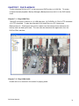
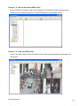
Chapter 7-3. Manage DVRs Download
To manage multiple DVRs file download, please use Backup Manager to download files
from DVRs. To perform DVRs file download, please first click on File->Add DVR. It
prompts Add DVR dialog box.
Chapter 7-4. Connect to DVR’s FTP Service.
After adding a DVR profile into the Tree View, please click on the Profile and click on
Connect button.
DVR User Manual
39
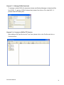
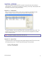
Chapter 7-5. Start to Download DVR’s Files.
Once a DVR is connected, a list of time stamps of the DVR gets listed in the treeview.
Select one of the stamp and click on Download button to download the files.
Chapter 7-6. Play local DVR’s files.
Click on the time stamp of the local driver, the file clips can by playback by clicking on the
Play button.
DVR User Manual
40
CHAPTER 8. NETWORK
There are two ways to access the DVR via network--Internet browser (web interface) or
CMX application. All the features including live monitoring, menu setup, video playback, and
file backup can be done by using web interface.
Chapter 8-1-1. Configuration
Make sure that network IP address, subnet mask, and gateway of the DVR are setup
correctly. Always, consult your network administrator before installing DVR.
To setup IP address, a user can use IPScan utility to scan all the DVRs within a LAN. This
powerful tool can help the user to monitor, to find, and to set IP configuration for all Merit
LILIN’s IP-based products.
Note: The default IP address of the DVR is 192.168.0.111
Chapter 8-1-2. Internet Ports
To access the DVR via Internet using a router, please make sure that IP Ports of the router
(IP sharing device) are set. The DVR uses the following IP Ports by default:
Port 80—HTML web pages
Port 3100—Command port
DVR User Manual
41
Chapter 8-2. Access the DVR via Internet Browser
To access the DVR, a user can use Internet browser to get live and stored video via Internet.
The DVR’s web interface also provides features of PTZ access, split window display, and
system configurations. General DVR web interface is described in the following figure:
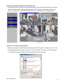
Chapter 8-2-1. Before Using Internet
Make sure that your Internet Browser allows signed ActiveX plug-in running on your PC. Set
“Download Signed ActiveX plug-in controls” to “Prompt” and “Run ActiveX control and plugin” to “Enable” at Internet Explore->Tools->Options->Security Settings.
DVR User Manual
42
Chapter 8-2-2. Logon
To logon the DVR, please type in the IP address in the HTTP address box via Internet
browser. By default, type “192.168.1.171” in the HTTP address box to access the logon
page. Use default password “1111” for Administrator, password “2222” for Operator, and
password “3333” for Guest.
Note: Each user can be assigned for different access level at System->Password/Access.
Chapter 8-2-3. Hyper Link Panel
Hyper Link Panel contains major features including video source, configuration, and Backup
Manager download page.
Configure the DVR via Web page
To configure the DVR via web page, please Click on “Configure” hyper link. There are
internal server setting, general network setting, PTZ device setting, and video system
setting allowed. The detail settings are described in the rest of the chapter.
Download H.264 DVR File Player
H.264 DVR File Player (Backup Manager) hyper link allows a user to download the
application via Internet.
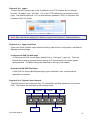
Chapter 8-2-4. Playback Over Network
The DVR allows a user to perform Play, FF, Pause/Step, and Stop operations on a remote
DVR. The buttons are described in the following figure:
FR
Playbac
Step
DVR User Manual
Pause
FR
Stop
43
To perform playback operation, please click on Playback hyperlink. A playback dialog box
shows up. Event search list, record search list, and time search are all integrated in the
dialog box on the hyper link panel.
Normal Record and Event Lists
Double click on the record list item or event list item for playback. A user can also click on
Search button to retrieve the video.
Time Search
Time search feature allows a user to search both master and slave HDDs by date and time.
To perform time search function, please specify date and time information in date and time
edit boxes. Press Search button to finish this task.
Chapter 8-2-5. Save JPEG file
To save live or playback video to JPEG files, please perform right mouse click on Video
Display Control area. In system menu, select Save All as JPEG or Save JPEG for the live or
playback video.
DVR User Manual
44
Chapter 8-2-6. Network Audio
The DVR can provide network audio monitoring for both live and playback video. To activate
network audio, please open a camera’s video in full screen on Video Display Control. It can
deliver network audio to a PC for both live and playback video.
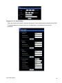
Chapter 8-3. Configure the DVR via Web page
Features of the DVR’s main menu system can be configured via web interface. Features
such as camera, alarm, recording, network, and backup can all get setup remotely.
Chapter 8-3-1. Camera Setting
Channel Enable—Enable or disable live video on
main monitor
Sequence Time—Camera sequence time for main
monitor
Chapter 8-3-2. Recording Setting
Current Rec Mode—Current DVR recording mode
HDD Overwritten—Option for circular recording
Camera Recording Mode--Assign schedule recording or no recording for a camera.
Camera Quality—Setup the recording quality for a camera
Camera FPS—recording frame rate for a camera
DVR User Manual
45
Chapter 8-3-3. Recording Schedule Table
A user can setup record schedule table via Internet, to setup scheduling table, please
specify day and time with the recording mode. The user can also use Apply
Chapter 8-3-4. Alarm Setting
Buzzer Enable—Enable/disable DVR buzzer
Motion Enable—Enable/disable motion detection
Motion Tracer—Enable/disable motion trace
Alarm Input Type—Set alarm input as NO/NC or disable
Buzzer Output Time—Assign buzzer time for each camera
Chapter 8-3-5. Alarm E-mail
Enable Alarm E-Mail—Option for enable alarm/motion email
From—From E-Mail address
To—To E-Mail address
Host/IP Address—SMTP mail server’s IP or DNS address
Authentication—Option for user and password
authentication
E-Mail Account—receiver’s E-Mail account
E-Mail Password—receiver’s E-Mail account’s password
DVR User Manual
46
Chapter 8-3-6. Network Setting
IP Addres.s—DVR’s IP address
Subnet Mask—Subnet mask
Gateway IP Address—Router/Gateway IP address
PPPoE account—PPPoE protocol account name
PPPoE password—PPPoE password
Video Port—The DVR’s video port
HTTP Port—HTML port number
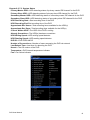
Chapter 8-3-7. System Setting
MAC Address: MAC address of the DVR
Firmware: firmware version of the DVR
DVR/485 ID: Addressable DVR ID for multiple DVRs remote control using remote controller
and RS-485 keyboard.
Language: Language selection of the DVR
Max Connections: Maximum network connections allowed for the DVR
Auto Logout: force to logout remote accesses.
Chapter 8-3-7-1. Timer
Date: Current date of the DVR
Time: Current time of the DVR
DST: Daylight saving time for a region
DVR User Manual
47
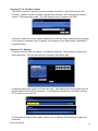
Chapter 8-3-7-2. User Setting
There are three levels (admin, operator and guest) of user authentication allowed in the DVR.
To change password, please specify the old password, new password, and confirm
password.
DVR User Manual
48
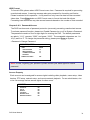
Chapter 8-3-7-3. System Status
Primary Master HDD—HDD detecting status of primary master IDE channel for the DVR
Primary Slave HDD—HDD detecting status of primary slave IDE channel for the DVR
Secondary Master HDD—HDD detecting status of secondary maser IDE channel for the DVR
Secondary Slave HDD—HDD detecting status of secondary slave IDE channel for the DVR
HDD Recording Start—Start recording time of the DVR
HDD Recording End-End recording time of the DVR
Approximate Rec Hours—Total recording hours available for the HDD(s)
Approximate Rec Days—Total recording days available for the HDD(s)
Current Written HDD—The HDD of the DVR in writing
Already Overwritten—The HDD(s) has been overwritten.
HDD Writing Speed—HDD writting speed detector
HDD Reading Speed—HDD reading speed detector
DVR ID—DVR ID/RS-485 ID
Number of Connections—Number of users accessing the DVR via network
Last Reboot Time—Last time for rebooting the DVR
Kernel—The OS version of the DVR
Temperature—DVR internal temperature indicator
Fan—Fan failure indicator
DVR User Manual
49
Chapter 8-3-7-4. Firmware update
This DVR is allowed to perform firmware upgrade via network. After DVR receives the
firmware, it starts to perform firmware upgrade automatically. After finishing the firmware
update, HTML page gets reload. The user can then start to operator the DVR.
To perform network firmware update, please click on Browse button and locate the firmware.
For 4-channel, 8-channel, and 16-channel, the firmware file are flash304.bin, flash308.bin,
and flash316.bin
Chapter 8-3-8. Backup
To perform remote video file backup, click Backup hyperlink. Please specify starting time
and ending time. Click on Submit button to perform file backup task.
A backup progress bar shows up on the web page. After backup task ends, please click on
the file hyperlink with LMP file extension. It can download the file from the DVR’s internal
HTTP server to your local PC.
To download the backup file(s) again, please click on “Backup File Download” hyperlink to
download.
DVR User Manual
50
APPENDIX
Appendix A. 4-Ch DVR Alarm I/Os and RS485 for PTZ
Pin 1
Pin 2
Pin 3
Pin 4
Pin 5
Pin 6
Pin 7
Pin 8
Pin 9
Pin 10
Alarm input 1
Alarm input 2
Alarm input 3
Alarm input 4
GND
ALARM NO (normal open)
ALARM NC (normal close)
COM
RS485+
RS485-
Appendix B. 8-Ch and 16-CH DVR Alarm I/Os and RS485 for PTZ
Pin 1
Pin 2
Pin 3
Pin 4
Pin 5
Pin 6
Pin 7
Pin 8
Pin 9
Pin 10
Pin 11
Pin 12
Pin 13
Pin 14
DVR User Manual
Alarm input 1
Alarm input 2
Alarm input 3
Alarm input 4
Alarm input 5
Alarm input 6
Alarm input 7
Alarm input 8
GND
ALARM NO (normal open)
ALARM NC (normal close)
COM
RS485+
RS485-
51
Appendix C. RS485 Input and Output Pin Assignment
Terminal
1
2
3
4
5
6
7
8
Name
----RS-485 – Out Link Keyboard
RS-485 + Out Link Keyboard
GND
DC +12V input
Appendix D. Hard Disk Drive Support List
Model
HDD Size
WD5000AVDS
500GB
WD5000AVVS
500GB
WD10EVDS
1TB
WD3200AVVS
320GB
WD2500AVVS
250GB
WD20EVDS
ST3500418AS
2TB
500GB
WD10EURS-630AB1
1TB
WD10EURS-630AB1
1.5TB
WD20EURS-63S48Y0
2TB
DVR User Manual
52
Appendix E. Supported USB-DVD/RW and Disks
Model
DRX-S30U-W
Manufacturer
SONY
Lite-On
eSAU108
Lite-On
eTAU108
Lite-On
eHAU424-01
Brand
Melody
RiTEK
Sony
OEM disk
Specification
DVD-RW
DVD-RW
DVD+R
DVD-R
Capacity
4.7GB
4.7GB
4.7GB
4.7GB
Max Speed
4x
8x
8x
8x
Note
Rewritable
Rewritable
Burn once
Burn once
Appendix F. Supported USB Flash Disk
Transcend 8G, 16G
Kingston 4G, 8G, 16G
Sanddisk 8G, 16G
DVR User Manual
53
Appendix G. Hard Disk Recording Table
Approximate recording days and hours can also be found at Menu->System->HDD Info.
Table 1. 8-Ch
Recording Quality
Highest
High
Standard
Low
Picture
size
5.8
KB/Pic
5.2
KB/Pic
4.0
KB/Pic
2.7
KB/Pic
500
GB
4
Days
5
Days
6
Days
9
Days
750
GB
6
Days
7
Days
9
Days
13
Days
1000
GB
9
Days
10
Days
13
Days
19
Days
2000
GB
18
Days
19
Days
25
Days
37
Days
HDD
Note: #1. Recording frame rate is 30 FPS * 8-Ch at CIF resolution.
#2. Above information may be inaccurate due to the installation environment.
#3. Recording Days calculate by a formula as following,
For example: 1TB HDD, Recording Quality Setting to = “Standard”
A day recording capacity of HDD =
4.0KB * 240 (Total FPS) *60 (Seconds) *60 (Minutes)* 24 (Hours) ÷ 1024 ÷ 1024 ≒ 79GB
Approx. 1TB recording day(s) = 1000 GB ÷ 79GB ≒ 13 Days
#4. Total FPS at CIF resolution calculate by a formula as following,
Total FPS = Channel number * Frame rate per channel
For example: 30 FPS * 8-Ch at CIF resolution; Total FPS (240 Frame) = 8-Ch * 30 FPS
Table 2. 8-Ch
Recording Quality
Highest
High
Standard
Low
Picture
size
19
KB/Pic
18
KB/Pic
12
KB/Pic
10
KB/Pic
500
GB
2
Days
2
Days
4
Days
5
Days
750
GB
4
Days
4
Days
6
Days
7
Days
1000
GB
6
Days
7
Days
8
Days
10
Days
2000
GB
10
Days
11
Days
16
Days
20
Days
HDD
Note: #1. Recording frame rate is 15 FPS * 8-Ch at D1 resolution.
#2. Above information may be inaccurate due to the installation environment.
#3. Recording Days calculate by a formula as following,
For example: 1TB HDD, Recording Quality Setting to = “Standard”
A day recording capacity of HDD =
12KB * 120 (Total FPS) *60 (Seconds) *60 (Minutes)* 24 (Hours) ÷ 1024 ÷ 1024 ≒ 118GB
Approx. 1TB recording day(s) = 1000 GB ÷118GB ≒ 8 Days
#4. Total FPS at D1 resolution calculate by a formula as following,
Total FPS = Channel number * Frame rate per channel
For example: 15 FPS * 8-Ch at D1 resolution; Total FPS (120 Frame) = 8-Ch * 15 FPS
DVR User Manual
54
Table 3. 16-Ch
Recording Quality
Highest
High
Standard
Low
Picture
size
6.0
KB/Pic
5.2
KB/Pic
3.2
KB/Pic
2.7
KB/Pic
500
GB
2
Days
3
Days
4
Days
5
Days
750
GB
3
Days
4
Days
6
Days
7
Days
1000
GB
4
Days
5
Days
8
Days
9
Days
2000
GB
8
Days
10
Days
16
Days
18
Days
HDD
Note: #1. Recording frame rate is 30 FPS * 16-Ch at CIF resolution.
#2. Above information may be inaccurate due to the installation environment.
#3. Recording Days calculate by a formula as following,
For example: 1TB HDD, Recording Quality Setting to = “Standard”
A day recording capacity of HDD =
3.2KB * 480 (FPS) *60 (Seconds) *60 (Minutes)* 24 (Hours) ÷ 1024 ÷ 1024 ≒ 129GB
Approx. 1TB recording day(s) = 1000 GB ÷ 129GB ≒ 8 Days
#4. Total FPS at CIF resolution calculate by a formula as following,
Total FPS = Channel number * Frame rate per channel
For example: 30 FPS * 16-Ch at CIF resolution; Total FPS (480 Frame) = 16-Ch * 30 FPS
Table 4. 16-Ch
Recording Quality
Highest
High
Standard
Low
Picture
size
19
KB/Pic
17
KB/Pic
13
KB/Pic
11
KB/Pic
500
GB
2
Days
3
Days
4
Days
5
Days
750
GB
4
Days
4
Days
6
Days
7
Days
1000
GB
5
Days
5
Days
8
Days
9
Days
2000
GB
10
Days
11
Days
16
Days
18
Days
HDD
Note: #1. Recording frame rate is 7.5 FPS * 16-Ch at D1 resolution.
#2. Above information may be inaccurate due to the installation environment.
#3. Recording Days calculate by a formula as following,
For example: 1TB HDD, Recording Quality Setting to = “Standard”
A day recording capacity of HDD =
13KB * 120 (Total FPS) *60 (Seconds) *60 (Minutes)* 24 (Hours) ÷ 1024 ÷ 1024 ≒ 129GB
Approx. 1TB recording day(s) = 1000 GB ÷129GB ≒ 8 Days
#4. Total FPS at D1 resolution calculate by a formula as following,
Total FPS = Channel number * Frame rate per channel
For example: 7.5 FPS * 16-Ch at D1 resolution; Total FPS (120 Frame) = 16-Ch * 7.5FPS
DVR User Manual
55
Models
Recording
Recording mode
Video source
Resolution
Recording NTSC
Recording PAL
Schedule
Backup
DVD/RW
Playback
Speed
Compression
Video Input
Camera Name
Live video
Video Output
VGA output
Backlight saving
Multiplexer
Digital zoom
Split screen
Spot monitor
Management
Reports
Authentication
Recording day
Alarm/event
Motion
Event
Email
Accessories
P/T/Z protocol
Keyboards
IR receiver
Mouse
Audio
Audio In/out
Remote control
Network
Protocols
Web
DVR status
IPScan
Software
BackupManager
Mobile phone
Others
WDT
DST
Multilanguage
CPU/OS
Power
Working Env.
Dimension
Weight
Specification
DVR304
DVR308
DVR316
SATA HDD: internal * 1
SATA HDD: internal * 2
External alarm / motion detection / schedule / manual
Analog * 4
Analog * 8
Analog * 16
Full D1: 720 * 576 (PAL) 720*480 (NTSC) / CIF: 320 * 288 (PAL) 320 * 240 (NTSC)
D1 120 / CIF 120 FPS
D1 120 / CIF 240 FPS
D1 120 / CIF 480 FPS
D1 100 / CIF 100 FPS
D1 100 / CIF 200 FPS
D1 100 / CIF 400 FPS
7 day * 24 hrs time table, recording mode configurable
USB 2.0 flash disk / HTTP file download / Audio supported
External USB DVD/RW
H.264 AVC video
FR: 2x, 4x, 8x, 16x, 32x, 64x / FF:2x, 4x, 8x, 16x, 32x, 64x
H.264 AVC and JPEG
Analog cameras
12 characters
PAL: 100 FPS/Sec
PAL: 200 FPS/Sec
PAL: 400 FPS/Sec
NTSC: 120 FPS/Sec
NTSC: 240 FPS/Sec
NTSC: 480 FPS/Sec
BNC * 1
BNC * 1 + Spot monitor
3D intellectual motion adoptive refinement with vivid image enhancement VGA engine up to 1920 * 1080i
LCD backlight saving mode
Sequence / digital zoom / freeze
ROI for 5X and 9X with PIP
No
4, PIP
4, 9
4, 9, 16
No
Yes
Yes
Full alarm, configuration, and operation reports exporting over HTTP or USB
User authentication with feature configurable
Dynamic recording day calculation
DI * 4 and DO * 2 (NO/NC)
DI * 8 and DO* 2 (NO/NC)
Motion grid 30*24 each channel, 8 sensitivities
External alarm, video loss, stop recording, power recovering, motion detection, schedule, logon, HDD format
Alarm notification with JPEG attachments
Remote controller addressable up to 255 DVRs
LILIN MLP2 and Pelco RS-485
None
PIH-931D keyboard
None
Extra IR extension connector, up to 200 m
USB / PS-2, drag-n-drop, right-mouse-click, mouse wheel.
G.711 audio, 0.7Vp-p, 16KHz
RCA 1 in, 1 output
RCA 4 in , 1 output
Yes
Direct Internet browser access / multiple users access
ARP / TCP/IP / UDP / HTTP / SMTP / FTP / DDNS / PPPoE / DynDNS / NTP
Live / event log & time search playback / AVI / snapshot
HTML DVR status
IPScan supported, easy-to-setup for IP address
Multiple DVRs FTP file download and multi-channel playback
iPhone, and Android mobile phone supported
Hardware watchdog timer
Daylight saving time
English, Chinese, Spanish, Danish, Swiss, Norwegian, Arabic, Japanese, Germany,
French, Polish, Portuguese, Simplified Chinese, Vietnam, Italian
32-bit RISC Processor, ARM926 SoC 336 MHz, Linux 2.6 kernel
DC 12V, 4.2A, 48W
DC 12V, 5.0A, 60W
Temp: 0℃ ~ +50℃ / Humidity: 0%~80%
290 mm * 52mm * 260mm
360mm * 60mm * 308mm
1.5 Kg
3.0 Kg
DVR User Manual
56
4/8/16CH DIGITAL VIDEO RECORDER
DVR304/308/316
MERIT LILIN ENT. CO., LTD
http://www.meritlilin.com
66-DVR304CSE
INSTRUCTION MANUAL