1
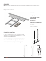
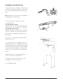
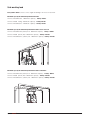
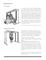
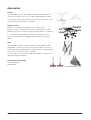
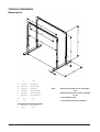
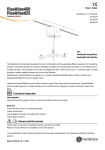
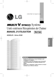
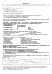
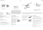
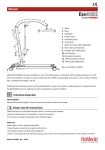
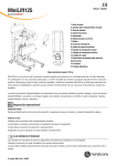
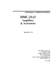
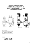
Pollux
Manual - English
SystemRoMedic
2
TM
3
3
4
1. Rail (not included)
1
3
2. Corner piece
2
3. Wing knob
4. Lift unit (not included)
3
5
5. Support legs
6. Support leg carrier handle
6
7. Locking knob for support legs
5
7
8. Base foot
6
8
Maxload: 600 kg/1320 lbs
7
8
Pollux is a freestanding lift stand which, in combination with two rails and two lift units, functions as a stationary patient
lift for heavier patients. It is particularly suitable in cases where the need for a stationary lift is occasional or in situations
where it is not possible to install a permanent rail system on the ceiling or walls. Pollux is made of aluminium, which
makes it very light in relation to its high lifting capacity.
Handicare’s SystemRoMedic product series includes a range of lifts, slings and other accessories. SystemRoMedic
adopts a holistic approach to patient transfers and is organized in four categories: transfer, positioning, support and
lifting.
Functional inspection
Visual inspection Inspect Pollux and lift unit functions regularly. Check to ensure that material is free from damage.
Before use:
Check to ensure that the lift stand and lift unit are correctly assembled.
Check all mounts and safety latches.
Always read the manual
Always read the manuals for all assistive devices used during a transfer.
Keep the manual where it is accessible to users of the product.
The lift may only be used by persons who have received instruction in the operation of the lift.
Manual nr: 756 En Ver. 3 130212
Table of contents
Assembly........................................................................................ 3-5
Component parts...................................................................................... 3
Assembly of support legs.......................................................................... 3
Assembly of rails and lift unit..................................................................... 4
Final inspection........................................................................................ 5
Using the product....................................................................... 5-8
Important information ............................................................................. 5
Placement............................................................................................... 5
Rails ..................................................................................................... 6
Safe working load..................................................................................... 7
Instructions for use................................................................................... 8
Accessories...................................................................................... 9
Maintenance...................................................................................10
Technical information................................................................ 11
Measurements........................................................................................11
2
M A N U A L SystemRoMedic
TM
Assembly
Note! Pollux must be assembled by authorized technicians. Assembly must be performed by at least two persons.
Components included:
1. 2 base feet
2. 4 support legs with carrier handles
3. Rails (not included - must be
ordered separately)
1
2
4. 4 corner pieces
4
3
5
16 wing knobs for assembling support
A
legs and rails
4 plates for guiding rails
B
Assembly of support legs
C
1. Insert two support legs into two base feet and adjust to the desired height for your Pollux lift stand. Use the wing knobs to secure
the support legs at the desired height.
2, 3. Insert a support leg into a corner piece and secure it with two
D
bolts. Do the same with the other support legs and corner pieces.
4. Mount the plates in the corner pieces with the wing knobs.
1
E
F
1
2
2
SystemRoMedic M A N U A L
TM
3
3
4
4
3
Assembly of rails and lift unit
5. Insert the rail into a corner piece. It must pass the
rear wing knob. The plate guides the rail and secures
it to the corner piece. Secure the rail with the wing
knob.
Note! Remember to mount the lift unit/carriage before
5, 9
assembling the other support leg.
6. Mount the lift unit according to one of the
following alternatives.
1. Lift unit with built-in carriage:
Guide the lift unit into the rail (see image) before the
other end of the rail is secured to the corner piece.
2. Lift unit with separate carriage:
Guide the carriage into the rail before the other end
6
of the rail is secured to the corner piece. When the
lift stand is fully assembled the portable lift unit can
be mounted.
For instructions on using the lift, see the manual for
the respective lift unit.
7. To prevent the lift unit from gliding along the rail
during assembly of the second support leg, anchor it
7
to the support leg that has already been assembled.
We recommend anchoring the lift unit with the help
of an end stop. When assembly is complete, slide
the end stop to the other end of the rail and leave it
in place.
8. Repeat steps 4-7 for the parallel support leg
which is mounted in the same base foot.
9. Screw the other sides of the rails to the other
corner pieces as shown in images 5, 9.
10. Completed assembly
10
4
M A N U A L SystemRoMedic
TM
Final inspection
Inspect Pollux for signs of damage. Check to ensure that Pollux is standing safely on the floor, so that it does not
lean, and that the support legs are adjusted to the same height.
Check to ensure that all wing knobs and bolts are securely tightened.
The lift unit must be inspected according to the procedure for periodic inspection for the respective lift unit.
Keep the manual where it is easily accessible for users of the product.
Using the product
Important information
• Pollux must be assembled according to the assembly instructions included with the lift stand.
• Pollux may only be used indoors and on a level floor.
• Lifting accessories must be properly tested to ensure that they correspond to the patient’s needs and functional ability.
• Never leave a patient unattended during a transfer.
• Max load may under no circumstances be exceeded. See section on max load.
• For optimal function, Pollux must be inspected regularly. See section on Maintenance.
• Warranty applies only if repairs or alterations are made by authorized personnel.
Placement
Pollux should always be placed so that the patient’s centre of gravity is directly under the rails. Otherwise, the direction
of pull will be off-centre, which may affect stability negatively. Therefore, during lifting from the bed, the rails must be
centred directly above the bed.
SystemRoMedic M A N U A L
TM
5
Rails
Spans by rail
230 kg / 507 lbs
Maximum span of single rail 64
250 cm / 98 (inch.)
170 cm / 67 (inch.)
Maximum span of single rail 120
500 cm / 196 (inch.)
400 cm / 157 (inch.)
Maximum span of single rail 160
700 cm / 275 (inch.)
1
500 cm / 196 (inch.)
2
1
A
285 kg / 625 lbs
4
3
2
6
5
4
3
7
6
5
8
7
8
A
A
A
Rail 64
Prod. no: B
B
50400123, 50400157, 50400125-127
B
B
Safe working load: 230-285 kg (505-625 lbs)
Built-in dimension: 64 mm (2,5 inch.)
Material: Aluminium
CC
C
C
64
64
Colour:
RAL 9010 as standard
Unit weight: 3,4 kg/m / 7,5 lbs.
L
D
60,3
D
L
D
D
60,3
Available lenghts:
2, 3, 4, 5 and 6 meters
E
E
1
(78, 118, 157, 196 and 236 inch.)
2
1
4
3
2
4
3
NAME
5
5
hc-jope
DRAWN
6
DATE
6
7
7
2010-03-30
8
8
APPROVED BY
NAME
IN WORK
STATUS:
A
A
TITLE
APPROVED BY
Unless otherwise stated, general
tolerances according toSTATUS:
ISO 2768-m
Rail 120
F
DATE
RAIL 642010-03-30
hc-jope
DRAWN
COMMENTS:
COMMENTS:
A
DWG. NO.
SIZE
REV.
IN
A3WORK
TITLE
-
MATERIAL:
6063-T6 orgeneral
equivalent
Unless otherwise stated,
tolerances according
toWEIGHT:
ISO 2768-m
SCALE:1:1
3.41 kg/m g
1
F
2
3
4
00A
RAIL 64
DWG. NO.
SIZE
SHEET 1 OF 1
A3
REV.
-
00A
MATERIAL:
6063-T6 or equivalent
Prod. no: 50400128-132
Safe working load: 230-285 kg (505-625 lbs)
Built-in dimension: 120 mm (4,7 inch.)
Material: Aluminium
SCALE:1:1
B
B
1
2
3
3.41 kg/m g
WEIGHT:
B
4
C
C
C
Colour:
RAL 9010 as standard
Unit weight: 5,3 kg/m / 11,7 lbs.
SHEET 1 OF 1
120
120
L
D
D
L
D
Available lenghts:
60,3
2, 3, 4, 5 and 6 meters
E
60,3
(78, 118, 157, 196 and 236 inch.)
DRAWN
NAME
DATE
hc-jope
2010-03-30
APPROVED BY
E
IN WORK
STATUS:
TITLE
COMMENTS:
Unless otherwise stated, general
tolerances according to ISO 2768-m
F
1
2
1
4
3
2
4
3
7
Rail 160
A
NAME
hc-jope-
IN WORK
SCALE:1:1
1
2
3
DATE
DWG. NO.
WEIGHT:
REV.
2010-03-30
7
00A
TITLE
5.33 kg/m g
A
A
Unless otherwise stated, general
tolerances according to ISO 2768-m
DWG. NO.
SIZE
A3
F
-
MATERIAL:
6063-t6 or equivalent
Prod. no: 50400133-135
Safe working load: 230-285 kg (505-625 lbs)
Built-in dimension: 160 mm (6,3 inch.)
Material: Aluminium
Colour:
RAL 9010 as standard
Unit weight: 6,2 kg/m kg / 13,7 lbs.
SCALE:1:1
1
2
3
C
5.33 kg/m g
S
B
B
C
C
160
C
160
L
D
WEIGHT:
4
B
B
Available lenghts:
RAIL 120
SHEET 1 OF 1
COMMENTS:
4
8
8
6063-t6 or equivalent
STATUS:
A
RAIL 120
SIZE
APPROVED MATERIAL:
BY
6
5
A3
DRAWN
6
5
L
D
D
D
5, 6 and 7 meters
(196, 236 and 275 inch.)
60,3
E
E
60,3
DRAWN
NAME
DATE
hc-jope
2010-03-30
APPROVED BY
STATUS:
COMMENTS:
APPROVED BY
STATUS:
Unless otherwise stated, general
tolerances according to ISO COMMENTS:
2768-m
TITLE
DATE
2010-03-30
RAIL
160
IN WORK
SIZE
A3
TITLE
DWG. NO.
6063-T6 or equivalent
F
2
3
00A
SIZE
4
WEIGHT:
6.20 kg/m g
MATERIAL:
2
3
REV.
-
4
SHEET 1 OF 1
00A
TM
6063-T6 or equivalent
SCALE:1:1
1
DWG. NO.
A3
M A N U A L SystemRoMedic
SCALE:1:1
1
RAIL 160
REV.
-
Unless otherwise stated, general
tolerancesMATERIAL:
according to ISO 2768-m
F
6
NAME
hc-jope
DRAWN
IN WORK
WEIGHT:
6.20 kg/m g
SHEET 1 OF 1
Safe working load
Rail system in Pollux consists of two single rail utilizing 1 lift motors in each rail.
Maximum capacity for Pollux lifting with one lift motor:
Lift motor RiseAtlas450 - Maximum capacity - 205 kg / 450 lbs
Lift motor Reda 230kg – Maximum capacity – 230 kg / 507 lbs
Lift motor RiseAtlas625 – Maximum capacity – 285 kg / 625 lbs
Maximum capacity for Pollux lifting with two lift motors one in each rail:
Lift motor RiseAtlas450 (205x2) 410 - Maximum capacity - 410 kg / 500 lbs
Lift motor Reda (230x2) 460 – Maximum capacity – 460 kg / 1014 lbs
Lift motor RiseAtlas625 (285x2) 570 – Maximum capacity – 570 kg / 1256 lbs
Maximum capacity for Pollux lifting with two lift motors in BariTurn:
Lift motor RiseAtlas450 (205x2) 410 - Maximum capacity - 410 kg / 900 lbs
Lift motor Reda (230x2) 460 – Maximum capacity – 460 kg / 1014 lbs
Lift motor RiseAtlas625 (285x2) 570 – Maximum capacity – 570 kg / 1256 lbs
SystemRoMedic M A N U A L
TM
7
Instructions for use
Transfers with Pollux
For transfers with Pollux, two lift units can be used separately
(one on each rail). If there is a need to pivot the lift units, BariTurn
can be used in combination with the lift system (see manual for
BariTurn). Plan the lift and fit the sling to the patient (see the user
manual for the sling model that is being used). Hook the loops to
the slingbars. Leg sections on one slingbar and back loops on
the other slingbar. Prepare the patient for the lift and explain what
is about to happen. Never leave the patient unattended during
the lifting and transfer procedure, and always be attentive to the
patient’s signals. Lift the patient by raising both lift units. Take
particular care to ensure that both lift units are raised evenly, so
as not to jeopardize the comfort and safety of the patient. Stop
when all lift straps are tensioned and check to ensure that all is
as it should be before proceeding with the lift. If the patient is
uncomfortable, stop lifting.
Transfer the patient from the bed to the wheelchair, or vice versa.
Gait training with Pollux and BariTurn
For gait training with Pollux, a BariTurn must be used. This is to
enable the patient to turn and walk in both directions. When the
BariTurn is mounted with two lift units (see manual for BariTurn)
on Pollux a lift vest can be placed around the patient (see manual
for the respective lift vest). Hook the loops to the slingbars:
Alternative 1: Hook the back loops to one slingbar, and then
hook the front loops to the other slingbar.
Alternative 2: Hook one of the front loops and one of the back
loops to one slingbar, and then hook the other loops to the other
slingbar.
Prepare the patient for the lift and explain what is about to
happen. Never leave the patient unattended during the lifting
and transfer procedure, and always be attentive to the patient’s
signals. Lift the patient by raising both lift units. Take particular
care to ensure that both lift units are raised evenly, so as not to
jeopardize the comfort and safety of the patient. Stop when all lift
straps are tensioned and check to ensure that all is as it should
be before proceeding with the lift. If the patient is uncomfortable,
stop lifting.
The patient can now train, with or without extra support. With the
help of BariTurn the lift units can travel between, and along, the
rails and can rotate.
8
M A N U A L SystemRoMedic
TM
Accessories
Lift units
SystemRoMedic’s lift units are available in different models and versions,
stationary or portable. The choice of model is determined by the need
for lifting capacity, the settings and situations in which the lift unit is to be
used, and the particular needs of the patient.
Lifting accessories
BariTurn is a swivelling carriage (360°) for two ceiling lift units.
BariTurn is used in combination with Pollux or a permanently installed
MilkyWay rail system for lifting very large and heavy patients, for example,
in connection with seated and horizontal transfers. BariTurn is also a
perfect assistive device for standing and gait training with very heavy
patients.
Slings
SystemRoMedic’s slings, which are available in several different fabrics
and materials, are part of a series of various sling models. The choice of
model and material is determined by the patient’s functional ability and by
the situations in which the sling is to be used.
For slings and other accessories, see SystemRoMedic’s manuals for the
respective slings and slingbars.
Assistive devices for positioning
SafeHandlingSheet
RoMedicClips.
RoMedicClips
SystemRoMedic M A N U A L
TM
SafeHandlingSheet
9
Maintenance
Pollux must be thoroughly inspected at least once per year. Inspection must be performed by authorized personnel and
in accordance with SystemRoMedic’s instructions for periodic inspection of Pollux.
Repairs and maintenance may only be performed by authorized personnel and with original spare parts.
Cleaning
When necessary, clean the lift stand with warm water or rubbing alcohol. Do not use cleaning agents containing phenol
or chlorine, as this may damage the material.
10
M A N U A L SystemRoMedic
TM
1
A
2
4
3
6
5
Technical information
Measurements
Samma mått som fö
Totalvikt och mått p
C
B
G
I
D
E
C
A
B
D
F
H
E
G
NAME
hc-mabr
DRAWN
201
APPROVED BY
Released
STATUS:
F
1
A
B
A
200-244
78,8-96,14
B
192-227
75,65-89,44
C
200-500
78,8-197
D
223-523
2
87,86-206,06
E
209-509
82,35-200,55
F
204-504
80,38-198,58
G
120
47,3
H
13
5,1
I
48,6-59,7
J
18,5
SystemRoMedic M A N U A L
TM
COMMENTS:
Unless otherwise stated, gener
tolerances according to ISO 2
3
Note: 4
Column A measurement is in cm and weight is in kg.
Column B measurement is in inches and weight is in lbs.
I is total weight of stand
J is the weight of the heaviest component
19,15-23,52
7,29
11
SystemRoMedic
TM
For 25 years we have applied ourselves wholeheartedly to developing smart and easy-to-use assistive devices for easy
transfers and to making life and work easier for both patients and personnel in the care sector.
Experience, innovation and training are the basis for SystemRoMedic, a total solution for every imaginable transfer
situation.
Transfer: products for moving patients between locations.
Positioning: products for repositioning in the same location.
Support: products that provide mobility support.
Lifting: products adapted for lifting.
The philosophy behind SystemRoMedic is to prevent occupational injuries while improving the patient’s sense of independence and dignity. Through a combination of training and a complete range of transfer-assistive devices,
SystemRoMedic offers the means to improving both the work environment and the quality of care while enabling
significant cost savings.
Our mission, to help people, has always been, and will continue to be, the driving force of innovation. We love easy
transfers.
Contact your local distributor if you have any questions about the product and its use. See www.handicare.com for a
complete list of distributors. Always make sure that you have the right version of the manual. The most recent editions of
manuals are available for downloading from our website, www.handicare.com
Handicare AB
Veddestav. 15, Box 640
SE-175 27 Järfälla
SWEDEN
Tel: +46 (0)8-557 62 200
Fax:+46 (0)8-557 62 299
E-mail: [email protected]
Internet: www.handicare.com