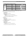
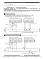
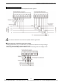
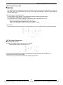
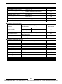
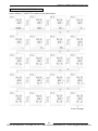
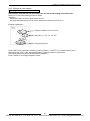
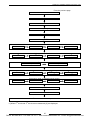
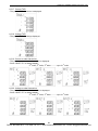
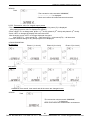
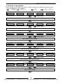
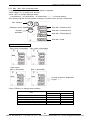
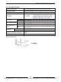
1
Phone: 800.894.0412 - Fax: 888.723.4773 - Web: www.ctiautomation.net - Email: [email protected]
Cautions for Your Safety
Read the manual carefully before installing, running and maintenance for proper operation.
Before using, master the knowledge of the equipment, safety information and all of other
notes.
This manual uses two safety flags to indicate different levels of danger.
A handling error could cause serious physical injury to an
operator and in the worst case could even be fatal.
●Always take precautions to ensure the overall safety of your system, so that the whole
system remains safe in the event of failure of this product or other external factor.
WARNING
●Do not use this product in areas with inflammable gas. It could lead to an explosion.
●Exposing this product to excessive heat or open flames could cause damage to the
lithium battery or other electronic parts.
●Do not open the secondary side of CT during power on the primary side current.
It might cause electric shock or CT breakdown.
A handling error could cause serious physical injury to an operator
or damage to the equipment.
●To prevent abnormal exothermic heat or smoke generation, use this product at the
values less than the maximum of the characteristics and performance that are assured
in these specifications.
●Do not dismantle or remodel the product. It could lead to abnormal exothermic heat or
smoke generation.
●Do not touch the terminal while turning on electricity. It could lead to an electric shock.
●Use the external devices to function the emergency stop and interlock circuit.
●Connect the wires or connectors securely. The loose connection might cause abnormal
exothermic heat or smoke generation.
●Do not allow foreign matters such as liquid, flammable materials, metals to go into the
inside of the product. It might cause exothermic heat or smoke generation.
●Do not undertake construction (such as connection and disconnection) while the power
supply is on.
●Never remove the terminal block under applying current to load.
It might cause electric shock or CT breakdown.
●Do not use at secondary side circuit of inverter. It might cause exothermic heat or
damage.
CAUTION
Copyright and trademark
●Panasonic Industrial Devices SUNX Co., Ltd. owns the copyright of this manual.
●We stiffly refuse the reproduction of without permission from this manual.
●Modbus Protocol is a communication protocol that the Modicon Inc. developed for PLC
and Modbus is the registered trademark of Schneider Electric.
● Other company names and the product names are the trademarks or registered
trademarks of each company.
Phone: 800.894.0412 - Fax: 888.723.4773 - Web: www.ctiautomation.net - Email: [email protected]
Introduction
Thank you very much indeed for purchasing
“KW9M Eco-POWER METER”.
In this manual, we explain the usage of “KW9M
Eco-POWER METER” in detail.
Please use it correctly after understanding the content
enough.
Phone: 800.894.0412 - Fax: 888.723.4773 - Web: www.ctiautomation.net - Email: [email protected]
Table of Contents
Cautions before using ...............................................................................................................................ⅰ
Chapter 1 Unit’s Outline ............................................................................................................................. 1
1.1 Measurement outline ............................................................................................................................... 1
1.2 Measurement items ................................................................................................................................. 2
1.3 Logging items........................................................................................................................................... 3
Chapter 2 Parts Name and Working .......................................................................................................... 5
2.1 Parts Names ............................................................................................................................................ 5
2.2 Key’s functions ......................................................................................................................................... 6
2.3 Indication on KW9M Eco-POWER METER ............................................................................................. 7
Chapter 3 Wiring......................................................................................................................................... 8
3.1 Main unit terminal arrangement ............................................................................................................... 8
3.2 Wiring Diagrams .................................................................................................................................... 10
3.3 How to attach the Current Transformer (CT) ......................................................................................... 12
3.4 For Input Connection ............................................................................................................................. 14
3.5 For Output Connection .......................................................................................................................... 14
3.6 RS485 Communication .......................................................................................................................... 15
3.7 Backup Battery for Clock ....................................................................................................................... 16
3.8 Low Voltage Directive ............................................................................................................................ 17
Chapter 4 Settings.................................................................................................................................... 18
4.1 Setting Flow ........................................................................................................................................... 22
4.2 Password entry ...................................................................................................................................... 24
4.3 Password initialize ................................................................................................................................. 25
4.4 How to Set ............................................................................................................................................. 26
4.4.1 Settings for power measurement ................................................................................................. 26
4.4.2 Settings for demand measurement .............................................................................................. 30
4.4.3 Settings for pulse measurement................................................................................................... 33
4.4.4 Settings for communication .......................................................................................................... 47
4.4.5 Settings for optional functions ...................................................................................................... 49
4.4.6 Settings for time program ............................................................................................................. 54
4.4.7 Settings for calendar timer ........................................................................................................... 55
4.4.8 Password setting .......................................................................................................................... 56
4.4.9 Confirmation window .................................................................................................................... 57
Chapter 5 Various Functions .................................................................................................................... 58
5.1 Pulse output function ............................................................................................................................. 58
5.1.1 Output depends on integral electric power ................................................................................... 58
5.1.2 Stand-by alarm ............................................................................................................................. 58
5.1.3 Under voltage alarm ..................................................................................................................... 58
5.1.4 Over voltage alarm ....................................................................................................................... 58
5.1.5 Power interruption alarm .............................................................................................................. 58
5.1.6 Under current alarm ..................................................................................................................... 58
5.1.7 Current alarm................................................................................................................................ 58
5.1.8 Power alarm ................................................................................................................................. 58
5.1.9 Other alarms ................................................................................................................................. 59
5.1.10 Output depends on count value ................................................................................................. 59
5.1.11 Level output ................................................................................................................................ 59
5.2 Counter function..................................................................................................................................... 59
5.3 Clock Correction Function ..................................................................................................................... 60
5.4 Demand function .................................................................................................................................... 60
5.4.1 Peak demand ............................................................................................................................... 60
5.4.2 Block interval demand .................................................................................................................. 60
5.4.3 30-min demand............................................................................................................................. 61
5.4.4 Current Demand ........................................................................................................................... 64
5.4.5 Max. demand value ...................................................................................................................... 64
5.4.6 Demand alarm output ................................................................................................................... 64
5.4.7 Working at power failure and at recovery..................................................................................... 64
Phone: 800.894.0412 - Fax: 888.723.4773 - Web: www.ctiautomation.net - Email: [email protected]
Chapter 6 Display of each Value.............................................................................................................. 65
6.1 Working of Monitor display .................................................................................................................... 65
6.2 Working of Monitor Display .................................................................................................................... 66
6.2.1 Single-phase two-wire system...................................................................................................... 66
6.2.2 Single-phase three-wire system ................................................................................................... 68
6.2.3 Three-phase three-wire system.................................................................................................... 71
6.2.4 Three-phase four-wire system...................................................................................................... 73
6.2.5 Instantaneous power .................................................................................................................... 77
6.2.6 Instantaneous power of each phase / each circuit ....................................................................... 77
6.2.7 Total integral power ...................................................................................................................... 78
6.2.8 Total integral export power ........................................................................................................... 79
6.2.9 Integral power of each phase / each circuit .................................................................................. 80
6.2.10 Integral export power of each phase / each circuit..................................................................... 81
6.2.11 Current........................................................................................................................................ 82
6.2.12 Voltage ....................................................................................................................................... 82
6.2.13 Power factor ............................................................................................................................... 83
6.2.14 Frequency................................................................................................................................... 83
6.2.15 Current unbalance ...................................................................................................................... 83
6.2.16 Voltage unbalancing ................................................................................................................... 83
6.2.17 Current THD ............................................................................................................................... 84
6.2.18 Voltage THD ............................................................................................................................... 84
6.2.19 Current n-order Harmonics......................................................................................................... 84
6.2.20 Voltage n-order Harmonics ........................................................................................................ 84
6.2.21 Pulse Input Value ....................................................................................................................... 85
6.2.22 Conversion value for integral active power ................................................................................ 85
6.2.23 Conversion value for integral export power ................................................................................ 86
6.2.24 Temperature ............................................................................................................................... 87
6.2.25 Calendar timer ............................................................................................................................ 87
6.3 Working of Logging Mode ...................................................................................................................... 88
6.3.1 Max. demand value ...................................................................................................................... 93
6.3.2 Max. / Min. value of electric power ............................................................................................... 94
6.3.3 Integral power ............................................................................................................................... 95
6.3.4 Max. /Min. value of each measured value .................................................................................... 96
6.4 Working of Demand Mode ..................................................................................................................... 98
6.4.1 Peak Demand ............................................................................................................................... 98
6.4.2 Block Interval Demand (Sliding block、fixed block) ...................................................................... 98
6.4.3 30-min. Demand ......................................................................................................................... 100
Chapter 7 How to update the firmware .................................................................................................. 102
7.1 How to install USB driver ..................................................................................................................... 102
7.2 How to update the firmware ................................................................................................................. 103
7.2.1 Connect PC and Eco-POWER METER ..................................................................................... 103
7.2.2 Prepare Eco-POWER METER to update ................................................................................... 103
7.2.3 Update the firmware using KW Version Upgrade Tool .............................................................. 103
Chapter 8 Specifications ........................................................................................................................ 107
8.1 Main unit .............................................................................................................................................. 107
8.2 Input Specifications .............................................................................................................................. 108
8.3 Output Specifications ........................................................................................................................... 109
8.4 Input Specifications .............................................................................................................................. 110
8.5 Demand monitor and control specifications (common to 9, 10) .......................................................... 111
8.6 Communication Specifications ............................................................................................................. 112
8.7 Self-diagnostic function ........................................................................................................................ 113
8.8 Power Failure Memory ......................................................................................................................... 113
Chapter 9 Mounting ................................................................................................................................ 114
9.1 Dimensions .......................................................................................................................................... 114
9.1.1 Main unit ..................................................................................................................................... 114
9.2 Panel mounting .................................................................................................................................... 114
Phone: 800.894.0412 - Fax: 888.723.4773 - Web: www.ctiautomation.net - Email: [email protected]
Cautions before using
■ About this product
Eco-POWER METER is designed chiefly to manage saving energy.
It is neither nor can it be legally used for billing.
■ Installation environment
◇Do not use the Unit in the following environments.
・Where the unit will be exposed to direct sunlight and where the ambient temperature is outside
the range of -25 to 55 °C.
・Where the ambient humidity is outside the range of 30 to 85 % RH (at 20℃), non-condensing
and where condensation might occur by sudden temperature changes
・Where inflammable or corrosive gas might be produced
・Where the unit will be exposed to excessive airborne dust or metal particles
・Where the unit will be exposed to water, oil or chemicals
・Where organic solvents such as benzene, paint thinner, alcohol, or strong alkaline solutions
such as ammonia or caustic soda might adhere to the product
・Where direct vibration or shock might be transmitted to the product, and where water might wet
the product
・Where the place near high-voltage cable, high-voltage device, power line, power device.
・Where the place near a machinery with transmission function such as amateur radio.
・Where the place near a machinery which occurs the big switching serge
◇Please use the Unit according to the specifications described in this manual. Otherwise, it
may malfunction or cause fire and an electric shock.
・Connect to the power supply in compliance with the rating.
・Refer to the wiring diagram to ensure proper wiring for the power supply, input and output.
・Do not perform wiring or installation with a live line. It may also lead to circuit burnout or fire by
way of the secondary CT side opening.
■ Installation
・Eco-POWER METER is designed to be used in a control panel.
・The power supply terminal and voltage input terminal of the main unit is common. Therefore if
additional noise effects the power supply line, incorrect measurements may result.
・Installation and wiring must be performed by expert personnel for electrical work or electric
piping.
・Never remove the terminal block under applying current to load.
It might cause electric shock or CT breakdown.
・Do not add an excess power to the display. It might break the inner liquid crystal.
・Although the case is made from fireproof resin, do not mount it next to flammable materials. Also,
avoid placing it directly on top of materials that catch fire easily.
・If the operating power supply surge exceeds the following value, the internal circuit could be
destroyed, so be sure to use a surge absorption element.
Surge wave form
[± (1.2/50) μs single-polarity full-wave voltage]
Surge voltage (%)
Surge voltage
6,000V
Standard surge waveform
The above value is the surge-voltage
resistance at ± (1.2/50) μs of
single-polarity full-wave voltage.
100
90
Peak
50
30
0
0
1.2
50
Time (μs)
i
Phone: 800.894.0412 - Fax: 888.723.4773 - Web: www.ctiautomation.net - Email: [email protected]
・External noise up to the level shown below is treated as noise voltage, but levels higher than this
could lead to malfunctioning or damage to the internal circuit. Although the case is made from
fireproof resin, do not mount it next to flammable materials.
Between operating power supply terminals
Noise voltage
1,500V
Noise wave form (noise simulator)
Rise time: Pulse width: 1 μs, 50 ns
Polarity: Cycle: 10 ms
Note) Accurate measurement may not be possible if excessive noise gets added to the input line.
・This product is designed to be used only with our options.
Options from other companies are not compatible.
■ As to measurement
・If there is some distortion by harmonic or waveform, it may not measure correctly.
Please check with the actual system before adopts it.
・It might not measure an instantaneous current such as an inrush current or an welding machine.
・When measuring the below loads, it might not satisfy with the accuracy guarantee.
Out of rating current, Load with low power factor,
Load with winding current, Load with ferromagnetic field
・Power factor operation is a method assuming balanced load. The error might be big when it
measures unbalanced load.
■ Static electricity
・Discharge static electricity touching the grounded metal etc. when you touch the unit.
・Excessive static electricity might be generated especially in a dry place.
■ Cleaning
・Wipe dirt of the main unit with soft cloth etc. When thinner is used, the unit might deform or be
discolored.
■ Power supply
・Connect a breaker to the voltage input part for safety reasons and to protect the device.
The breaker that connects to the voltage input part must arrange at the position easily reached,
and display shows it is the breaker of the equipment.
・Do not turn on the power supply or input until all wiring is completed.
■ Before power on
Please note the following points when turning on power at the first time.
・Confirm there are neither wiring rubbish nor especially an electrical conduction when installed.
・Confirm neither the power supply wiring, the I/O wiring nor the power-supply voltage are wrong.
・Tighten the installation screw and the terminal screw surely.
・Use an electric wire applicable to the rated current.
■ Before change the setup
Set the password carefully.
In order to avoid unexpected change the settings, it can set password. However, if you forget the
password you can’t change the settings.
We recommend you to note the password when you set and change the password.
ii
Phone: 800.894.0412 - Fax: 888.723.4773 - Web: www.ctiautomation.net - Email: [email protected]
KW9M Eco-POWER METER Advanced type
Chapter 1 Unit’s Outline
With KW9M Eco-POWER METER, electrical power (voltage, current, etc.), power factor, frequency, etc
are measured using AC voltage and AC current input via one of the following systems: single-phase
two-wire system, single-phase three-wire system, three-phase three-wire system or three-phase
four-wire system.
This has built-in thermistor to measure the temperature of installation place such as inside the panel
board for your reference.
■Eco-POWER METER is designed chiefly to manage saving energy. It is neither intended nor
can it be legally used for billing.
Model number
AKW92112
Model name
KW9M Eco-POWER METER Advanced type
1.1 Measurement outline
Phase/Wire system
Single-phase two-wire
Single-phase three-wire
Three-phase three wire
Three-phase four-wire
(1P2W)
(1P3W)
(3P3W)
(3P4W)
Applicable power system
100V system, 200V system, 400V system
Measurement circuit
1-circuit (when measuring 1P2W: max. 3-circuit)
Input measurement voltage
0 to 500VAC
Input measurement current
1 to 65,535A
Applicable current sensor
Secondary side current: 1A or 5A
(common)
1
Phone: 800.894.0412 - Fax: 888.723.4773 - Web: www.ctiautomation.net - Email: [email protected]
KW9M Eco-POWER METER Advanced type
1.2 Measurement items
Item
Instantaneous
power
Integral power
(import)
Integral power for
each time zone
(4-zone) (import)
Integral power
(export)
Integral power for
each time zone
(4-zone) (export)
Active
Reactive
Apparent
Active
Reactive
Apparent
Active
Reactive
Apparent
Active
Unit
kW
kvar
kVA
kWh
kvarh
kVAh
kWh
kvarh
kVAh
kWh
Reactive
kvarh
Active
kWh
Reactive
kvarh
Display data range
Present value
-99999 to 0.000 to 99999
Max. value
Min. value
0.000 to 9999999.9
* Total integral power (import)
Present value
0.000 to 29999999
0.000 to 9999999.9
Present value
0.000 to 9999999.9
* Total integral power (export)
0.000 to 29999999
Present value
0.000 to 9999999.9
Present value
Current
A
0.000 to 99999
Voltage
V
0.00 to 99999
Power factor
*1
*1
-1.000 to 1.000
Frequency
Hz
0.00 to 99.99
Pulse count value
Power conversion value
Temperature
*1
Present value
Max. value
Min. value
Present value
Max. value
Min. value
Present value
Max. value
Min. value
Present value
Max. value
Min. value
Present value
Present value
Present value
0.000 to 99999999
0.000 to 99999999
degree C
-100.0 to 100.0 *1
January 1, 2000 00:00:00 –
Calendar
Present value
December 31, 2099 23:59:59
*1 ‘Display data range’ is the range to be able to indicate with the main unit display, it is not a range that
can be measured.
・Power Quality
Item
Unbalanced current
Unbalanced voltage
Current THD
(total harmonic distortion)
Voltage THD
(total harmonic distortion)
Current harmonics
(2nd to 31st )
Voltage harmonics
(2nd to 31st )
Each phase
Each phase
Unit
%
%
Display data range
0.000 to 999.99
0.000 to 999.99
Each phase
%
0.000 to 400.00
Each phase
%
0.000 to 400.00
Each phase
%
0.000 to 400.00
Phase
Line
%
%
0.000 to 400.00
0.000 to 400.00
2
Phone: 800.894.0412 - Fax: 888.723.4773 - Web: www.ctiautomation.net - Email: [email protected]
KW9M Eco-POWER METER Advanced type
・Demand
Item
Unit
Display data range
Active
kW
Reactive
kvar
Apparent
kVA
Present demand
*1
0.000 to 99999
Active (export)
kW
Reactive (export)
kvar
Current
A
Estimated demand
*2
kW
0.000 to 99999
Ratio of estimated demand
*2
%
0.000 to 99999
Integral power converted by pulse *2
kWh
0.000 to 999999.99
* Please use this demand function as your standard.
The demand value calculated with this function is not guaranteed.
*1 When peak demand is set, only current demand is available.
When 30-min.demand is set, active power demand and current demand are available.
*2 Only when 30-min demand is set.
1.3 Logging items
Measurement max. value
for each month
Measurement min. value
for each month
(with time stamp*)
Item
Power
Current
Voltage
Power factor
Frequency
Unbalanced current
Unbalanced voltage
Max. demand value
(active power, reactive power, apparent power, export active power,
export reactive power, current)
(with time stamp*)
Voltage interruption
Over voltage
Power quality *
(with time stamp for occurrence Under voltage
date and period)
Over current
Under current
OUT1
Pulse output occurrence date
(time stamp)
OUT2
Record
12 records (for 12-month)
12 records (for 12-month)
12 records (for 12-month)
12 records (for 12-month)
12 records (for 12-month)
12 records (for 12-month)
12 records (for 12-month)
12 records (for 12-month),
Max. value
Up to 10 records
Up to 10 records
Up to 10 records
Up to 10 records
Up to 10 records
Up to 10 records
Up to 10 records
* Time stamps and power quality data can be confirmed via communication. They are not displayed.
3
Phone: 800.894.0412 - Fax: 888.723.4773 - Web: www.ctiautomation.net - Email: [email protected]
KW9M Eco-POWER METER Advanced type
<Glossary>
Eco-POWER METER defines as below.
THD
Ratio of harmonic distortion (voltage or current) for the fundamental frequency.
(total harmonic
Lower the value shows that the distortion is less.
distortion)
Sinusoidal wave other than fundamental frequency.
It has frequency that is whole-number multiple of the fundamental frequency.
Harmonics
The frequency that has 2 times frequency (half wavelength) is called 2nd-order
harmonics.
Voltage
The different between each phase-voltage due to the load unbalancing.
unbalancing
It is calculated as below.
|Max. (Min.) voltage of all phase-average voltage|
Average voltage
Current
unbalancing
The difference between each-phase current due to the load unbalancing.
It is calculated as below.
|Max. (Min.) current of all phase-average current|
Average current
Power
interruption
Under voltage
Under current
Over current
Demand by
IEC61557-12
×100 (%)
×100 (%)
Voltage under 5% of rating is kept 100ms or more,
Set the ratio for the rated voltage and it is used for threshold.
Voltage under the set ratio is kept 100ms or more, it will judge as under voltage.
Set the ratio for the rated current and it is used for threshold.
Current under the set ratio is kept 100ms or more, it will judge as under current.
Set the ratio for the rated current and it is used for threshold.
Current over the set ratio is kept 100ms or more, it will judge as over current.
Based on IEC61557-12 Performance measuring and monitoring devices (PMD)
It calculates by measured power via CT with setting interval.
Set power interval by 1 to 60(min.) (every 1-min.). It calculates demand
during latest finished interval and displays.
One interval is started every setting time.
It calculates by measured power via CT with setting interval.
Set power interval by 1 to 60 (min.) (every 1-min.) It calculates demand
fixed block interval
demand during latest finished interval and displays. After one interval finishes, the
next interval starts.
It calculates based on a thermal demand meter.
Current demand
It measures an average current (current demand) within setting interval and
the max. value is considered as max. current demand.
This works for electric power input by CR or pulse.
30-min demand
It measures using power during 30-min. and calculates average (kW).
Max. value of 1-month is recorded and displayed.
Max. value of instantaneous power during 1-month is considered as a peak
Peak demand
demand. Peak demand of 12-month is recorded for 4 time-zones.
Sliding block interval
demand
4
Phone: 800.894.0412 - Fax: 888.723.4773 - Web: www.ctiautomation.net - Email: [email protected]
KW9M Eco-POWER METER Advanced type
Chapter 2 Parts Name and Working
2.1 Parts Names
<Front>
4
<Back>
9
17
18
16
1
5
2
13
3
14
15
6
8
7
10
11
12
2) Auxiliary mark
Measuring mode
Setting mode
Measuring mode
Indicate the measuring item
Indicate the setting item
Indicate the power condition
3) TX/RX mark
Measuring mode
Blinking while communication
4) Load ratio indicator
Measuring mode
Indicate the ratio of load (current) for the rating
5) Lock mark
Measuring mode
Lighting while in lock mode
6) Unit mark
Measuring mode
Indicate the measuring unit
Measuring mode
Indicate the measuring value
Setting mode
Indicate the setting value
Use to operate the unit
1) Item indicator
7) Measurement value
8) Key
19
9) Terminal A
10) Terminal B
11) USB port
12) Mounting clip
13) Log indication
USB communication port
Use to panel mounting (screws :M4×10mm)
Logging mode
Indicate log type
Measuring mode
14) Pulse output
Logging mode
Lighting when pulse is output
Indicator
Demand mode
Measuring mode
15) Pulse input
Logging mode
Lighting when pulse is input
Indicator
Demand mode
Measuring mode
16) Alarm indicator
Logging mode
Lighting when alarm is output
Demand mode
17) Terminal C
18) Battery label
19) Backup battery
Backup clock and logging data
5
Phone: 800.894.0412 - Fax: 888.723.4773 - Web: www.ctiautomation.net - Email: [email protected]
KW9M Eco-POWER METER Advanced type
*1 Auxiliary mark [LEAD] [LAG] indicates the phase difference between voltage and current.
When current phase delays to voltage phase, [LAG] is indicated.
When current phase leads to voltage phase, [LEAD] is indicated.
When power factor is ‘1’, ‘0’ and ‘-1’, it doesn’t display [LEAD] nor [LAG].
2.2 Key’s functions
Key
Functions
Measuring mode
<MODE>
<SET>
<SET>
(continuous 3-sec)
<SHIFT/▽>
<ITEM/△>
Setting mode
Logging mode
Demand mode
Setting mode
<MODE>+<SHIFT/▽>
Shift to setting mode
Set setting items and setting values
Shift to measuring item
Logging mode
Measuring mode
Logging mode
Demand mode
Lock mode
Select logging item to display
All keys locked
Measuring mode
Select measuring item to display
Release the lock mode
Setting mode
Select a setting value
Logging mode
Select logging item to display
Demand mode
Select demand item to display
Select measuring item to display
Logging mode
Select logging item to display
Demand mode
Select demand item to display
Measuring mode
Shift to logging mode
Logging mode
Shift to demand mode
Demand mode
Shift to measuring mode
Measuring mode
<SET>+<ITEM/△>
Shift to setting confirmation mode and measuring mode
Measuring mode
Measuring mode
<SET>+<SHIFT/▽>
Shift to setting mode
Select measuring item to display
Logging mode
Select logging item to display
Demand mode
Select demand item to display
●Lock mode
It is the mode makes all keys unable. In this mode, you can not input by any keys.
When you press <SET> continuously for about 3sec., lock mark is displayed.
Press <SET> continuously for about 3sec. again to release Lock mode.
When it set to use auto-display functions, the display items are changed automatically.
Refer to 4.4.3 setting for optional functions for auto-display functions.
6
Phone: 800.894.0412 - Fax: 888.723.4773 - Web: www.ctiautomation.net - Email: [email protected]
KW9M Eco-POWER METER Advanced type
2.3 Indication on KW9M Eco-POWER METER
The alphabet is shown as below.
7
Phone: 800.894.0412 - Fax: 888.723.4773 - Web: www.ctiautomation.net - Email: [email protected]
KW9M Eco-POWER METER Advanced type
Chapter 3 Wiring
Be sure to wire correctly according to the terminal arrangement and wiring diagrams.
Please connect a fuse or a breaker to power supply part for safety reasons and to protect the device.
This has no built-in power switch, circuit breaker or fuse for measured voltage input parts.
Therefore it is necessary to install them in the circuit near this unit.
Do not turn on the power supply or input until all wiring is completed.
3.1 Main unit terminal arrangement
Terminal block A
10P
Terminal block C
8P
Terminal block B
8P
USB port
Battery label
Terminal block A
Terminal
1
2
3
4
5
6
number
L+
V1
V2
V3
Vn
N-
Functions
Power supply
Measured voltage input
*Do not use NC (vacant) terminals in any purpose.
Terminal block C
Terminal
1
number
Functions
OUT1
7
8
9
10
NC
SG
A+
B-
vacant
RS485
2
3
4
5
6
7
8
COM1
OUT2
COM2
IN1+
IN1-
IN2+
IN2-
Output 1
Output 2
Input 1
Input 2
*It is insulated between OUT1 and OUT2.
*Minus terminals of input terminal are connected internal.
Terminal block B
Terminal
1
number
K
Functions
CT1
2
3
4
5
6
7
8
L
K
L
K
L
K
L
CT2
CT3
CTn
Measured current input
8
Phone: 800.894.0412 - Fax: 888.723.4773 - Web: www.ctiautomation.net - Email: [email protected]
KW9M Eco-POWER METER Advanced type
The input voltage to each terminal is as follows.
Terminal Phase and wire system Terminal No.
1-2
Power
Single-phase two-wire
supply
(L+ - N-)
3-6
Single-phase two-wire
(V1-Vn)
3-5-6
Single-phase three-wire
Measured
(V1-V3-Vn)
voltage
3-5-6
input
Three-phase three-wire
(V1-V3-Vn)
3-4-5-6
Three-phase four-wire
(V1-V2-V3-Vn)
Input voltage
85-264V AC [ 85-264V
100-300V DC [100-300V
]
]
0-500VAC [0-500V
]
(L-L)
0-500VAC [0-500V
0-250VAC [0-250V
:3W]
:3W]
(L-L)
(L-N)
0-500VAC [0-500V 3
]
(L-L)
0-500VAC [0-500V 3
0-289VAC [0-289V 3N
]
]
(L-L)
(L-N)
◆Applicable wire (Crimp-type terminal is recommended.) ・Stripping length: 7 to 8mm
・Power supply/Measured voltage/RS485 communication
Terminal block: A
Screw size: M2.5
Tightening torque: 0.4 to 0.5N・m
Sectional area
single /stranded wire 0.5 to 4mm2(AWG20 to12)
・for 2pcs.
single/stranded wire 2pcs.×0.5 to 2mm2 (AWG20 to 14)
*Use shielded wire for RS485 communication.
・Output/Input
Terminal block: C
Screw size: M2
Tightening torque: 0.2 to 0.25N・m
Sectional area:
single /stranded wire 0.5 to 1.5mm2(AWG20 to16)
・CT Input (Measured current)
Terminal block: B
Screw size: M2.5
Tightening torque: 0.4 to 0.5N・m
Sectional area:
single /stranded wire 0.5 to 4mm2(AWG20 to12)
*Use applicable wire according to the measured current.
9
Phone: 800.894.0412 - Fax: 888.723.4773 - Web: www.ctiautomation.net - Email: [email protected]
KW9M Eco-POWER METER Advanced type
3.2 Wiring Diagrams
Please connect a breaker or a fuse to the power supply and voltage input part for safety reasons and to
protect the device.
・Recommended breaker: 3 to 15A
・Recommended fuse : Time-lag fuse rated current 2A
Grounding the secondary side of VT (Voltage transformer) and CT (Current transformer) is not
necessary with low-voltage circuit.
*When using several CTs, set each CT approximately 1m apart. If the two CTs are set too close each
other, it may not measure accurately due to magnetic field interference.
◆When measuring a load with rated input voltage
Single-phase two-wire system
*One CT is needed to measure single-phase two-wire system.
*2 CTs are needed to measure 2-circuit and 3 CTs are needed to measure 3-circuit.
*To measure 2-circuit, wire 3 and 4. To measure 3-circuit, wire 3 and 4 and 5.
Single-phase three-wire/Three-phase three-wire
*2 CTs are needed to measure single-phase three-wire system, three-phase three-wire system.
10
Phone: 800.894.0412 - Fax: 888.723.4773 - Web: www.ctiautomation.net - Email: [email protected]
KW9M Eco-POWER METER Advanced type
Three-phase four-wire system
*3 CTs are needed to measure three-phase four-wire system.
Vn terminal should be connected to N-phase which is grounded.
◆When measuring a load with exceed input voltage
Voltage transformer (VT) is needed when you measure a load with over input voltage.
Use a VT, those secondary voltage rating is 110V.
Grounding the secondary side of VT and CT is not necessary with low-voltage circuit.
11
Phone: 800.894.0412 - Fax: 888.723.4773 - Web: www.ctiautomation.net - Email: [email protected]
KW9M Eco-POWER METER Advanced type
3.3 How to attach the Current Transformer (CT)
DANGER
●Never open the secondary circuit of CT under applying current to load.
●Never remove the terminal block under applying current to load.
Will cause electric shock or breakdown CT
・Use CT that the secondary side current is 5A or 1A, the rated burden 0.5VA or more.
・One CT is needed for 1 unit when measuring 1P2W (2 CTs for 2-circuit, 3CTs for 3-circuit). Two CTs
are needed when measuring 1P3W/3P3W. Three CTs are needed when measuring 3P4W.
Using all CTs for one unit should be the same.
・Use the applicable wire, or it might cause a breakdown, burnout or electric shock.
・When connecting CT, connect the secondary side to the terminal of the main unit first, and after that
wire the primary side to a load electric wire. Incorrect order might cause an electric shock or break CT.
・The CT has polarity. Wire correctly according to the K and L marks. Wrong direction can’t measure
correctly.
・If there is some distortion by harmonic or waveform, it may not measure correctly.
Please check with the actual system before adopts it.
・Separate the wiring (strong electric part) of the measured voltage input terminal (operating power
supply terminal) from the CT cable. It may not satisfy the accuracy due to noise.
12
Phone: 800.894.0412 - Fax: 888.723.4773 - Web: www.ctiautomation.net - Email: [email protected]
KW9M Eco-POWER METER Advanced type
◆How to connect CT
(1) Power off the measured devices.
(2) Install applicable CT.
(3) Remove terminal block of KW9M.
(4) Connect CT to the terminal block.
(5) Insert terminal stand surely.
(6) After confirm all wiring correct, turn on the power of the load and KW9M.
* Connect CT wiring and terminal block surely.
It will cause CT breakdown.
* Never remove the terminal block under applying current to
load. It will cause electric shock or breakdown CT.
(Connection example)
Power supply
Ammeter etc.
Breaker
Primary side current
K
Secondary current
CT with 2nd current 1A/5A
Without Ammeter
k
l
L
Load
◆How to set the parameters for CT
(1) Select CT type (CT-T) according to the using CT.
(Select ‘5A’ if secondary side current of using CT is 5A. Select ‘1A’ if secondary side current
of using CT is 1A.)
(2) Set the primary current of measured CT at primary side current of CT setting mode (CT-1).
< ex > If the measured CT is 400A/1A or 400A/5A, set to”400”.
(3) Connect CT according to the CT direction, power side (K) to load side (L).
13
Phone: 800.894.0412 - Fax: 888.723.4773 - Web: www.ctiautomation.net - Email: [email protected]
KW9M Eco-POWER METER Advanced type
3.4 For Input Connection
●Pulse input
・Contact input
Use highly reliable metal plated contacts. Since the contact’s bounce time leads directly to error in
the count value, use contacts with as short a bounce time as possible. In general, select 30Hz for
max.counting speed.
・Non-contact input (Transistor input)
Connect with an open collector. Use the transistor with the following specifications.
VCEO=20V min. IC=20mA min. ICBO=6μA max
Use transistors with a residual voltage of less than 3V when the transistor is ON.
*`Short-circuit impedance should be less than 1kΩ.
Open-circuit impedance should be more than 100kΩ.
(When the impedance is 0Ω, drain current is approx. 10mA.)
・Input wiring
Please wire as short as possible by using a shielded wire or a metallic electric wire tube individually.
3.5 For Output Connection
●PhotoMOS relay output
・It adopts PhotoMOS relay output, there is no polarity.
Output: Rated capacity 30V AC/DC, 0.1A
・Do not connect devices that voltage or load exceeds the rated capacity (30V AC/DC,0.1A)
・Please wire less than 100m fir output.
If it is long, it may not work correctly due to floating capacitance.
14
Phone: 800.894.0412 - Fax: 888.723.4773 - Web: www.ctiautomation.net - Email: [email protected]
KW9M Eco-POWER METER Advanced type
3.6 RS485 Communication
・When using shielded cable for the RS485 transmission line, ground one end.
Use a class D dedicated earth for grounding. Do not share a ground with other earth lines. (Fig. 1)
・ For terminal stations of both side including the upper device, termination resistors should be
connected. KW9M Eco-POWER METER doesn’t have any built-in termination resistors.
Connect 120Ω, 1/2W or more termination resistor between [A+] and [B-] of Eco-POWER METER that
is connected the end of RS485 transmission line. The RS485 transmission line shielded cable should
be grounded at the end KW9M Eco-POWER METER. (Fig. 1)
・Be sure to connect with daisy chain the RS485 transmission line between each unit.
Do not use a splitter. (Fig. 2)
・To avoid noise, separate the transmission line from high-voltage line (power supply, voltage line).
(Fig.1)
(Fig.2)
Correct wiring
Terminal
station
Terminal
station
○
Incorrect wiring
×
◆How to connect KW9M and the other devices with 2-wire system
15
Phone: 800.894.0412 - Fax: 888.723.4773 - Web: www.ctiautomation.net - Email: [email protected]
KW9M Eco-POWER METER Advanced type
Recommended Cable
Use the transmission cables shown below for Eco-POWER METER RS485 communication system.
Conductor
Insulator
Cable
Resistance
Applicable cable
Cable
diameter
Size
Material
Thickness
(at 20℃)
HITACHI
1.25 mm2
KPEV-S
Max.
Approx.
(AWG16) Max.16.8Ω/km Polyethylene
0.5 mm
8.5 mm
1.25 mm2×1P
or more
TwistedBelden Inc. 9860
pair
HITACHI
2
with shield 0.5 mm
KPEV-S
Max.
Approx.
(AWG20) Max.33.4Ω/km Polyethylene
0.5 mm
7.8 mm
0.5 mm2×1P
or more
Belden Inc. 9207
2
VCTF
0.75 mm
Max.
Approx.
VCTF
(AWG18) Max.25.1Ω/km PVC
0.75 mm2×2C
0.6 mm
6.6 mm
or more
(JIS)
Cable
Section
Shield
Twisted-pair
with shield
Conductor
Jacket
Insulator
Notes
1) Use shielded type twist cables.
2) Use only one type of the transmission cables.
2) Do not mix different types of the cables.
3) Use twist pair cables under a bad noise environment.
Jacket
VCTF
Conductor
Insulator
3.7 Backup Battery for Clock
It is possible to backup the clock with backup battery for 1-month. In order to charge full, it is necessary
to turn on the power for 2 days. If it turns off within 2 days from first installation, it may not backup the
clock for 1-month.
16
Phone: 800.894.0412 - Fax: 888.723.4773 - Web: www.ctiautomation.net - Email: [email protected]
KW9M Eco-POWER METER Advanced type
3.8 Low Voltage Directive
For using under the measurement category III, install varistors or SPD between the lines of power
supply and the measured voltage input. Use the varistors or SPD which is complied with European
standard and specifications to meet power supply and added current.
When using in the application conforming to EN61010-1/IEC61010-1, make sure to satisfy the following
conditions.
1) RS485 communication part and pulse input part secure only basic insulation. In order to secure
reinforced (double) insulation demanded by EN 61010-1/ IEC61010-1, secure basic insulation or
more with load side and reinforced (double) insulation with RS485 communication system side.
2) Provide the voltage input part with an EN60947-1 or EN60947-3 compliant circuit breaker.
3) Use a wire with basic insulation or more for a wire cramped (or connected) CT
4) Vn terminal should be connected to N-phase which is grounded.
【Environmental conditions】
・Overvoltage category Ⅱ, Pollution degree 2
・Indoor use
・An ambient temperature of -25 to +55℃
・An ambient non-condensing humidity of 30 to 85%RH (at 20℃)
・Altitude of 2000m or less
【Mount the product in a place with】
・A minimum of dust, and an absence of corrosive gases
・No flammable, explosive gasses
・Few mechanical vibrations or shocks
・No exposure to direct sunlight
・No large capacity electromagnetic switches or cables through which large current is flowing
17
Phone: 800.894.0412 - Fax: 888.723.4773 - Web: www.ctiautomation.net - Email: [email protected]
KW9M Eco-POWER METER Advanced type
Chapter 4 Settings
You can set parameters for measuring and the other functions using the keys on Eco-POWER METER.
After wiring Eco-POWER METER and CT, power on and set the parameter for power measurement,
Eco-POWER Meter can measure the electric power. In order to use the other functions, set other
parameters according to your use.
◆Keys’ functions at setting mode
<MODE>
<SET>
<SHIFT/▽>, <ITEM/△>
Shift to setting mode
Set the items and values
Select items and change values
◆Parameters for power measurement
Item
Phase/Wire system
CT type
Primary side current of CT
Rated voltage
VT ratio
Over voltage (ON threshold)
Over voltage (OFF threshold)
Under voltage (ON threshold)
Under voltage (OFF threshold)
Over current (ON threshold)
Over current (OFF threshold)
Under current (ON threshold)
Under current (OFF threshold)
Conversion rate (P) total
Conversion rate (P) time-zone1
Conversion rate (P) time-zone2
Conversion rate (P) time-zone3
Conversion rate (P) time-zone4
Conversion rate (-P) total
Conversion rate (-P) time-zone1
Conversion rate (-P) time-zone2
Conversion rate (-P) time-zone3
Conversion rate (-P) time-zone4
Range
1P2W, 1P3W, 3P3W 3P4W
1, 5 [A]
1 to 65535 [A]
100 to 500 [V]
1.00 to 600.00
100.0 to 120.0 [%]
100.0 to 120.0 [%]
5.0 to 100.0 [%]
5.0 to 100.0 [%]
0.1 to 120.0 [%]
0.1 to 120.0 [%]
0.0 to 100.0 [%]
0.0 to 100.0 [%]
0.00 to 99.99/1kWh
◆Parameters for demand measurement
Item
Range
Peak (Peak demand),
Slide (Sliding block),
Power demand type
Fixed (Fixed block),
30min (30-min demand)
Power demand interval 1
1 to 60 [min.]
Power demand interval 2
1 to 60 [min.]
30-min demand calculation
Add (addition), Avg (average)
method
Power input
CT (CT input), PM (Pulse input)
kWh (electric power),
Pulse unit
PLS (pulse constant)
Pulse rate
0.001 to 100.000 [kWh]
(convert to electric power)
Pulse constant number
50000[pulse/kWh], 2000[pulse/kWh]
Current interval
1 to 60 [min.]
Initial value
1P2W
5A
5A
100V
1.00
105.0%
105.0%
95.0%
95.0%
100.0%
100.0%
0.0%
0.0%
10.00
Initial value
Peak
15
1
Add
CT
kWh
1.000
50000
15
18
Phone: 800.894.0412 - Fax: 888.723.4773 - Web: www.ctiautomation.net - Email: [email protected]
KW9M Eco-POWER METER Advanced type
◆Parameters for pulse input
Item
Pulse input (IN1)
Clock correction time
Pulse input (IN2)
Pre-scale (IN1,IN2)
Unit for pulse output
(OUT1,OUT2)
Target phase for pulse output
(OUT1,OUT2)
electric power
Target phase
current
for alarm
Power
output
interruption
(OUT1,OUT2) Over voltage
Under voltage
Integral direction (OUT1,OUT2)
Stand-by alarm (threshold)
(OUT1,OUT2)
Stand-by alarm (start time)
(OUT1,OUT2)
Stand-by alarm (phase)
(OUT1,OUT2)
Power alarm
(active/reactive/apparent)
threshold (ON/OFF)
(OUT1,OUT2)
PF alarm threshold (ON/OFF)
(OUT1,OUT2)
Over frequency alarm
threshold (ON/OFF)
(OUT1,OUT2)
Under frequency alarm
threshold (ON/OFF)
(OUT1,OUT2)
Voltage harmonics
alarm threshold (ON/OFF)
(OUT1,OUT2)
Current harmonics
alarm threshold (ON/OFF)
(OUT1,OUT2)
Current THD alarm threshold
(ON/OFF) (OUT1,OUT2)
Voltage THD alarm threshold
(ON/OFF) (OUT1,OUT2)
Voltage unbalancing alarm
threshold (ON/OFF)
(OUT1,OUT2)
Current unbalancing alarm
threshold (ON/OFF)
(OUT1,OUT2)
Range
30, Clock (clock correction)
00:00 to 23:59
30, 2000
0.001 to 100.000
0.0001, 0.001, 0.01, 0.1, 1, 10, 100
(kWh/1pulse)
AL-S, AL-oV, AL-uV, AL-C, AL-uC,
AL-MS, AL-P, AL-Q, AL-S, AL-PF, AL-oF,
AL-uF, AL-VH, AL-CH, AL-VT, AL-CT,
AL-VU, AL-CU, AL-PD, AL-CD Cnt1, Cnt2,
PL-L
Initial value
30
00:00
30
1.000
0.001
Total, Phase1, Phase2, Phase3
total
Total, All(ALL) , Phase1, Phase2, Phase3
All(ALL) , Phase1, Phase2, Phase3, N 相
total
All
All(ALL) , Phase1, Phase2, Phase3,
Line 1-2, line 2-3, line 3-1
All
P, -P
P
0.1 to 100.0 [%]
100.0
0 to 9999 [sec.]
0
Phase1, Phase2, Phase3, All
All
0.0 to 2999999.9 [kW/kvar/kVA]
2999999.9
0.000 to 1.000
0.000
0.00 to 100.00 [Hz]
100.00
0.00 to 100.00 [Hz]
0.00
0.00 to 400.0 [%]
400.00
0.00 to 400.0 [%]
400.00
0.00 to 400.0 [%]
400.00
0.00 to 400.0 [%]
400.00
0.00 to 999.99 [%]
999.99
0.00 to 999.99 [%]
999.99
19
Phone: 800.894.0412 - Fax: 888.723.4773 - Web: www.ctiautomation.net - Email: [email protected]
KW9M Eco-POWER METER Advanced type
Item
Power demand alarm power
type (ON/OFF) (OUT1,OUT2)
Power demand alarm
threshold(ON/OFF)(OUT1,OUT2)
Power demand alarm
hysteresis (OUT1,OUT2)
Power demand alarm start time
(OUT1,OUT2)
Current demand alarm
threshold (OUT1,OUT2)
Preset value (OUT1,OUT2)
Range
P, Q, S, -P, -Q
Initial value
P
0.000 to 99999.999 [kW/kvar/kVA]
0
0 to 100% [%]
0
1 to 30 [min.]
10
0.0 to 120.0 [%]
0
0 to 999999
0
◆Parameters for communication
Item
Range
MEWTOCOL, MODBUS(RTU),
Protocol
DL/T645-2007
MEWTOCOL
1 to 99
Device number
MODBUS(RTU)
1 to 247
DL/T645-2007
0 to 9999
Transmission speed
38400, 19200, 9600,4800, 2400, 1200 [bps]
8b-o(8bit odd), 8b-n(8bit none),
Transmission format
8bit-E(8bit even)
Stop bit
1,2
Response time
1 to 99 [ms]
◆Parameters for optional functions
Item
Range
Auto-off
0 to 99 [min.]
Luminance
1, 2, 3, 4, 5 (1: dark to 5:light)
Alarm blinking
ON, OFF
Update cycle
100 to 1000 [ms]
Auto-display
0 to 99 [min.]
Display cycle
1 to 99 [sec.]
Temperature correction
-100.0 to 100.0
Reset all integral value
YES, NO
Reset integral value 1
YES, NO
Reset integral value 2
YES, NO
Reset integral value 3
YES, NO
Reset count value 1
YES, NO
Reset count value 2
YES, NO
Reset logging data
YES, NO
Version
Initial value
MEWTOCOL
1
19200
8b-o
1
5
Initial value
1
3
OFF
100
10
5
0.0
NO
NO
NO
NO
NO
NO
NO
20
Phone: 800.894.0412 - Fax: 888.723.4773 - Web: www.ctiautomation.net - Email: [email protected]
KW9M Eco-POWER METER Advanced type
◆Parameters for time program
Item
time-zone
Program 1
start-time
time-zone
Program 2
start-time
time-zone
Program 3
start-time
time-zone
Program 4
start-time
time-zone
Program 5
start-time
time-zone
Program 6
start-time
time-zone
Program 7
start-time
time-zone
Program 8
start-time
time-zone
Program 9
start-time
time-zone
Program 10
start-time
<Initial setting for time program >
KW9M
0
1
2
3
4
5
6
7
Range
T1, T2, T3, T4, OFF
00:00 to 23:59
T1, T2, T3, T4, OFF
00:00 to 23:59
T1, T2, T3, T4, OFF
00:00 to 23:59
T1, T2, T3, T4, OFF
00:00 to 23:59
T1, T2, T3, T4, OFF
00:00 to 23:59
T1, T2, T3, T4, OFF
00:00 to 23:59
T1, T2, T3, T4, OFF
00:00 to 23:59
T1, T2, T3, T4, OFF
00:00 to 23:59
T1, T2, T3, T4, OFF
00:00 to 23:59
T1, T2, T3, T4, OFF
00:00 to 23:59
8
10
3-term(PG-3)
T2
11
12
13
14
15
16
17
18
19
20
21
22
23
24
6-term(PG-6)
5-term(PG-5)
7-term(PG-7)
8-term(PG-8)
2-term(PG-2)
T3
T4
9
4-term(PG-4)
T1
Initial value
T4
00:00
T3
6:00
T2
8:00
T1
10:00
T2
12:00
T1
14:00
T2
16:00
T3
22:00
OFF
―
OFF
―
1-term(PG-1)
◆Calendar timer
Item
Calendar timer
Range
January 1st, 2000 00:00:00
to December 31st ,2099 23:59:59
Initial value
◆Password
Item
Password change
0000 to 9999
Range
Initial value
0000
21
Phone: 800.894.0412 - Fax: 888.723.4773 - Web: www.ctiautomation.net - Email: [email protected]
KW9M Eco-POWER METER Advanced type
4.1 Setting Flow
Arrow mark means press each key
<MODE>
<SET>
<ITEM/△>
<SHIFT/▽>
Measuring value
display
Enter password
Setting mode
【Power
measurement】
Phase/Wire
【Demand】
Power demand
type
【Pulse】
【Communication】
【Optional functions】
【Time program】
【Calendar timer】
【Password】
Pulse input 1
Protocol
(To next page)
CT type
Power demand
interval 1 *1
Clock
synchronize *3
Device number
Primary side
current of CT
Power demand
interval 2 *1
Pulse input 2
Transmission
speed
Rated voltage
Calculation method
for 30-min demand *2
VT ratio
Power input type
*2
Over voltage
Pulse type
*2
Under voltage
Pulse rate
(electric power
conversion) *2
Over current
Pulse constant
value *2
Under current
Current demand
interval
Pre-scale 1
*4
Transmission
format
Pre-scale 2
Stop bit
Pulse output 1
Response time
Pulse output 2
Conversion rate(P)
Total, T1-4
Conversion rate(-P)
Total, T1-4
22
Phone: 800.894.0412 - Fax: 888.723.4773 - Web: www.ctiautomation.net - Email: [email protected]
KW9M Eco-POWER METER Advanced type
Setting mode
【Communication】
【Optional
functions】
【Time program】
【Calendar timer】
【Password】
Auto-off
Program 1
Calendar timer
Password
setting
(To previous page)
Program 2
Luminance
Program 3
Alarm blinking
Reset integral
value 2 *6
Update cycle
Reset integral
value 3 *6
Auto-display
Reset count
value 1 *6
Display cycle
*5
Reset count
value 2 *6
Temperature
correction
Reset logging
data *6
Reset all
integral value
Version
Reset integral
value 1 *6
Confirmation mode
*7
Program 7
*7
*7
Program 8
Program 4
*7
*7
Program 9
Program 5
*7
*7
*7
Program 10
*7
Program 6
Setting confirmation
NO
Setting confirmation
YES
Measuring value display
Press <SET> during each item is displayed to change the setting value.
Press <MODE> to display the confirmation window. Select [YES] and press <SET> to decide the
setting value. However no value is changed, the confirmation window is skipped and it displays the
measuring value display.
*1 It skips when [Peak] or [30min] is set at power demand type.
*2 It skips when except [30min] is set at power demand type.
*3 It skips when [30] is set at pulse input 1.
*4 It skips when [Clock] is selected at pulse input 1.
*5 It skips when [0] is set at auto-display setting.
*6 It skips when [YES] is selected at reset all integral value.
*7 It skips when [OFF] is selected at the previous program.
23
Phone: 800.894.0412 - Fax: 888.723.4773 - Web: www.ctiautomation.net - Email: [email protected]
KW9M Eco-POWER METER Advanced type
4.2 Password entry
It is necessary to enter password to shift to setting mode.
Enter [0000] and shift to password setting mode when you set password at the first time.
*When setting password, be careful for handling and note it.
Measuring value display
Press <MODE> and it shifts to password entry window.
Enter password from left to right using <ITEM/△>, <SHIFT/▽>.
Increase
Shift entered digit to the right
Press <SET> after enter the password.
If the password is correct, it shift to setting mode of power
measurement.
If the password is wrong, [FAIL] is displayed and it returns to the
password entry window.
*If you make wrong password 5 times, you can’t set 1-hour after.
24
Phone: 800.894.0412 - Fax: 888.723.4773 - Web: www.ctiautomation.net - Email: [email protected]
KW9M Eco-POWER METER Advanced type
4.3 Password initialize
When you forget the password, initialize it in the following procedures. (Initial: [0000])
It is impossible to decode the set password.
Measuring value display
Press <MODE> and it shifts to password entry window.
Press <MODE> and <ITEM/△> for 30 seconds in the password entry
window, and it shift to the password initialize window.
30 seconds
Not initialize : [NO]
Initialize
: [YES]
Return to the measuring value display
25
Phone: 800.894.0412 - Fax: 888.723.4773 - Web: www.ctiautomation.net - Email: [email protected]
KW9M Eco-POWER METER Advanced type
4.4 How to Set
■Set before measuring.
Select setting item with <ITEM/△> and press <SET>, and the value will be blinking.
Set with <ITEM/△> and <SHIFT/▽>.
When you select [YES] with the confirmation window and press <SET>, the setting values are
settled.
4.4.1 Settings for power measurement
Phase/Wire system
Select phase/wire system to measure.
Press <ITEM/△>, <SHIFT/▽> to select phase/wire system.
[Set list] 1P2W, 1P3W, 3P3W, 3P4W (initial: 1P2W)
* When the system is not matched with the measure system, it doesn’t measure correctly.
CT type
Select using CT type (secondary side current).
Press <ITEM/△>, <SHIFT/▽> to select CT type.
[Set list] 5 (5A), 1 (1A) (initial: 5)
To use CT with secondary side current 5A; [5]
To use CT with secondary side current 1A: [1]
Primary side current of CT
Set the primary side current of using CT.
Enter the primary side current of CT that is set at CT type setting.
Press <ITEM/△>, <SHIFT/▽> to set.
[Set range] 1 to 65535 (initial:5)
Increase
decrease
Primary side current of using CT is 400A: [400]
26
Phone: 800.894.0412 - Fax: 888.723.4773 - Web: www.ctiautomation.net - Email: [email protected]
KW9M Eco-POWER METER Advanced type
Rated voltage
Set the rated voltage to measure.
Press <ITEM/△>, <SHIFT/▽> to set the rated voltage.
[Set range] 100 to 500 (initial:100)
Increase
decrease
VT ratio
Select the voltage input method, input voltage directly or uses a voltage transformer
(VT: secondary side rating 110V) and set VT ratio.
Press <ITEM/△>, <SHIFT/▽> to set.
[Set range] 1.00 to 600.00 (initial:1.00)
increase
decrease
Input directly without VT: [1.00]
Use VT
: [1.01 to 600.00]
*When input voltage is under 3V (VT ratio = 1), [0.0] is displayed and it doesn’t measure.
Over voltage /Over voltage 2
Set a ratio of voltage for rated voltage used for threshold to judge over voltage and to clear the
over voltage.
At [over volt] window set a ratio of voltage to judge over voltage.
Press <ITEM/△>, <SHIFT/▽> to set the ratio.
[Set range] 100.0 to 120.0% (initial:105.0)
Increase
decrease
Press <SET>, and [over volt 2] is displayed. At this window, set a ratio of voltage to clear overt voltage.
Press <ITEM/△>, <SHIFT/▽> to set the ratio.
[Set range] 100.0 to 120.0% (initial:105.0)
Increase
decrease
ex.) Settings; [over volt] 120.0%, [over volt 2] 105.0%
When measured voltage is over 120.0%, it judges over voltage and output alarm.
During output the alarm, if the measured voltage becomes fewer than 105.0%, it will clear the
alarm.
27
Phone: 800.894.0412 - Fax: 888.723.4773 - Web: www.ctiautomation.net - Email: [email protected]
KW9M Eco-POWER METER Advanced type
Under voltage / Under voltage 2
Set a ratio of voltage for rated voltage used for threshold to judge under voltage and to clear the
under voltage.
At [under volt] window set a ratio of voltage to judge under voltage.
Press <ITEM/△>, <SHIFT/▽> to set the ratio.
[Set range] 5.0 to 100.0% (initial:95.0)
Increase
decrease
Press <SET>, and [under volt 2] is displayed. At this window, set a ratio of voltage to clear under
voltage.
Press <ITEM/△>, <SHIFT/▽> to set the ratio.
[Set range] 5.0 to 100.0% (initial:95.0)
Increase
decrease
ex.) Settings; [under volt] 95.0%, [under volt 2]
When measured voltage is under 95.0%, it judges under voltage and output alarm.
During output the alarm, if the measured voltage becomes over 100.0%, it will clear the alarm.
Over current / Over current 2
Set a ratio of current for rated current used for threshold to judge over current and to clear the
over current.
At [over curr] window set a ratio of current to judge over current.
Press <ITEM/△>, <SHIFT/▽> to set the ratio.
[Set range] 0.1 to 120.0% (initial:100.0)
Increase
decrease
Press <SET>, and [over curr 2] is displayed. At this window, set a ratio of current to clear over current.
Press <ITEM/△>, <SHIFT/▽> to set the ratio.
[Set range] 0.1 to 120.0% (initial:100.0)
Increase
decrease
ex.) Settings; [over curr] 120.0%, [over curr 2] 105.0%
When measured current is over 120.0%, it judges over current and output alarm.
During output the alarm, if the measured current becomes fewer than 105.0%, it will clear the
alarm.
28
Phone: 800.894.0412 - Fax: 888.723.4773 - Web: www.ctiautomation.net - Email: [email protected]
KW9M Eco-POWER METER Advanced type
Under current / Under current 2
Set a ratio of current for rated current used for threshold to judge under current and to clear the
under current.
At [under curr] window set a ratio of current to judge under current.
Press <ITEM/△>, <SHIFT/▽> to set the ratio.
[Set range] 0.0 to 100.0% (initial: 0.0)
Increase
decrease
Press <SET>, and [under curr 2] is displayed. At this window, set a ratio of current to clear under
current.
Press <ITEM/△>, <SHIFT/▽> to set the ratio.
[Set range] 0.0 to 100.0% (initial: 0.0)
Increase
decrease
ex.) Settings; [under curr] 95.0%, [under curr 2] 100.0%
When measured current is under 95.0%, it judges under current and output alarm.
During output the alarm, if the measured current becomes 100.0%, it will clear the alarm.
Conversion rate (P)
Set the conversion rate per integral active power 1 kWh.
Press <ITEM/△>, <SHIFT/▽> to set.
[set range] 0.00 to 99.99/1kWh (initial:10.00)
increase
decrease
Conversion rate (-P)
Set the conversion rate per integral export power (-P) 1kWh.
Press <ITEM/△>, <SHIFT/▽> to set.
[set range] 0.00 to 99.99/1kWh (initial:10.00)
increase
decrease
29
Phone: 800.894.0412 - Fax: 888.723.4773 - Web: www.ctiautomation.net - Email: [email protected]
KW9M Eco-POWER METER Advanced type
4.4.2 Settings for demand measurement
Power demand type
Select type of power demand measurement.
Press <ITEM/△>, <SHIFT/▽> to select power demand type.
[Set list]
Peak (peak demand), Slide (sliding block), Fixed (fixed block), 30min (30-min demand) (initial: Peak)
Power demand interval 1
* It skips this when [Peak] or [30min] is set for power demand type.
Set interval time to use for sliding block and fixed block for power demand measurement.
Press <ITEM/△>, <SHIFT/▽> to set.
[Set range]
1 to 60 min. (initial: 15)
Increase
Decrease
Power demand interval 2
* It is only when [Slide] is selected for power demand type.
Set slide time to use for sliding block for power demand measurement.
Press <ITEM/△>, <SHIFT/▽> to set.
[Set range]
1 to 60 min. (initial: 1)
Increase
decrease
Calculation method for 30-min demand
* It is only when [30min] is selected for power demand type.
Select calculation method for 30-min demand.
Press <ITEM/△>, <SHIFT/▽> to select.
[Set list] Add(addition), Avg(average)
(initial: Add)
30
Phone: 800.894.0412 - Fax: 888.723.4773 - Web: www.ctiautomation.net - Email: [email protected]
KW9M Eco-POWER METER Advanced type
Power input type
*It is only when [30min] is selected for power demand type.
Select input type to use for demand measurement, current measurement or pulse input.
‘CT’; Use current measurement via CT for demand measurement.
‘PM’; Use pulse input for demand measurement.
Count value by pulse input2 is used for power input.
Press <ITEM/△>, <SHIFT/▽> to select.
[Set list] CT(current measurement),
PM(Pulse input)
(initial: CT)
Pulse type
*It is only when [PM] is selected for power input type.
Select pulse type to input.
‘kWh’; Set electric power value per 1-pulse directly.
‘PULSE’; Use pulse constant value of pulse output device to use.
Press <ITEM/△>, <SHIFT/▽> to select.
[Set list] kWh, PULSE (initial: kWh)
Pulse rate (electric power conversion)
* It is only when [kWh] is selected for pulse type.
Set electric power value per 1-pulse.
Press <ITEM/△>, <SHIFT/▽> to set.
[Set range] 0.001 to 100.000 [kWh]
Increase
Decrease
Pulse constant value
* It is only when [PULSE] is selected for pulse type.
Select pulse constant value input by an outer pulse detector.
Check and select the pulse constant value of using pulse detector.
Press <ITEM/△>, <SHIFT/▽> to select.
[Set list] 50000(pulse/kWh), 2000(pulse/kWh)
(initial: 50000)
31
Phone: 800.894.0412 - Fax: 888.723.4773 - Web: www.ctiautomation.net - Email: [email protected]
KW9M Eco-POWER METER Advanced type
Current demand interval
Set interval to use for current demand calculation.
Press <ITEM/△>, <SHIFT/▽> to set.
[Set range] 1 to 60 min. (initial: 15)
Increase
Decrease
32
Phone: 800.894.0412 - Fax: 888.723.4773 - Web: www.ctiautomation.net - Email: [email protected]
KW9M Eco-POWER METER Advanced type
4.4.3 Settings for pulse measurement
Pulse input IN1 IN2
Select pulse input max. counting speed or select to use pulse input for clock correction.
Press <ITEM/△>, <SHIFT/▽> to select.
[Pulse input IN1: Set list]
30(Hz), Clock (clock correction) (initial: 30)
[Pulse input IN2: Set list]
30(Hz), 2000(Hz) (initial: 30)
Clock synchronize
* It skips when [30] is selected for Pulse input IN1.
Set time to correct the clock by using pulse input IN1.
*If KW9M clock is different 1-hour or more from the setting time when pulse is input to IN1, it doesn’t
correct the clock.
Press <ITEM/△>, <SHIFT/▽> to set.
[Set range] 00:00 to 23:59 (initial: 00:00)
Increase
decrease
Pre-scale N1 IN2
* It skips when [Clock] is selected for Pulse input IN1.
Set pre-scale value used to convert count value of pulse input.
Press <ITEM/△>, <SHIFT/▽> to set .
[Set range]
0.001 to 100.00 (initial: 1.000)
Increase
decrease
33
Phone: 800.894.0412 - Fax: 888.723.4773 - Web: www.ctiautomation.net - Email: [email protected]
KW9M Eco-POWER METER Advanced type
Unit for pulse output OUT1 OUT2
Set unit used for pulse output.
Press <ITEM/△>, <SHIFT/▽> to select unit for pulse output.
↓
To the next page
34
Phone: 800.894.0412 - Fax: 888.723.4773 - Web: www.ctiautomation.net - Email: [email protected]
KW9M Eco-POWER METER Advanced type
* [AL-PD] is skip when [Peak] is selected for
Power demand type.
[Set list] integral value (kWh/1pulse): 0.0001, 0.001, 0.01, 0.1, 1, 10, 100,
AL-S (stand-by alarm), AL-uV (under voltage alarm), AL-oV (over voltage alarm),
AL-MS (power interruption alarm), AL-uC (under current alarm), AL-C (current alarm),
AL-P (active power alarm), AL-Q (reactive power alarm), AL-S (apparent power alarm),
AL-PF (power factor alarm), AL-oF (over frequency alarm), AL-uF (under frequency alarm),
AL-VH (voltage harmonics alarm), AL-CH (current harmonics alarm),
AL-VT (voltage THD alarm), AL-CT (current THD alarm), AL-VU (voltage unbalancing alarm),
AL-CU (current unbalancing alarm), AL-PD (Power demand alarm),
AL-CD (current demand alarm), Cnt1 (count output), Cnt2 (count output), PL-L (level output)
(initial: 0.001)
・When one of AL-uV(under voltage alarm), AL-oV(over voltage alarm), AL-uC (under current alarm),
AL-C(current alarm) is set, alarm is output according to the settings of under voltage, over voltage,
under current, over current.
・When AL-MS(power interruption alarm) is set, alarm is output when it detects voltage under 5% of
rated voltage.
・When PL-L(level output) is set, when the designated data register is 1, it output.
It is necessary to control by outer device. Write 1 (output ON) or 0 (output OFF) to the designated data
register (OUT1:DT00005, OUT2:DT00006).
* Notes for selecting integral value
Select unit for pulse output so that pulse is less than 1-pulse for 1 second.
35
Phone: 800.894.0412 - Fax: 888.723.4773 - Web: www.ctiautomation.net - Email: [email protected]
KW9M Eco-POWER METER Advanced type
Target phase for pulse output/ alarm (OUT1 OUT2)
*It skips when [AL-VU, AL-CU, AL-PD, Cnt1, Cnt2, PL-L] is selected for unit for pulse output.
Select phase to monitor in order to judge the output.
It differs according to the setting unit and phase/wire systems.
Press <ITEM/△>, <SHIFT/▽> to select.
Set unit
Set list
total, Phase1, Phase2, Phase3 (initial: total)
Integral value
・For 3P3W, it fixes total. Setting window is skipped.
total, All, Phase1, Phase2, Phase3 (initial: total)
AL-P, AL-Q, AL-S
(Power alarm)
・For 3P3W, it fixes total. Setting window is skipped.
AL-S (Stand-by alarm)
AL-UC, AL-uC, AL-CH,
All, Phase1, Phase2, Phase3 (initial: All)
AL-CT,AL-CD
All, Phase1, Phase2, Phase3 (initial: All)
AL-PF, AL-oF, AL-uF,
・For 3P3W, it can’t be selected. Setting window is skipped.
All, Phase1, Phase2, Phase3 (initial: All)
AL-C
・For 3P4W: All*, Phase1, Phase2, Phase3, Phase-n (initial: All)
*Except Phase-n
All, Phase1, Phase2, Phase3 (initial: All)
AL-uV, AL-oV,
AL-MS, AL-VH, AL-VT
・For 3P3W: All, Line1-2, Line2-3, Line3-1
(initial: All)
*Selecting [All], it output when one of voltage of phase1, phase2 or phase3 exceeds (or falls below) the
threshold.
Selecting [total], it output when total voltage of phase1, phase2 and 3 exceeds (or falls below) the
threshold.
[Setting window display] example of OUT1
total
Phase1
All
Line 1-2
Phase2
Line 2-3
Phase3
Line 3-1
Phase-n
36
Phone: 800.894.0412 - Fax: 888.723.4773 - Web: www.ctiautomation.net - Email: [email protected]
KW9M Eco-POWER METER Advanced type
Direction of integral power for pulse output (OUT1 OUT2)
Select the direction of power (import or export) for using as a threshold for pulse output when
unit for pulse output set to ‘integral value’.
Press <ITEM/△>, <SHIFT/▽> to select.
[Set list] P(import), -P(export)
(initial: P)
Stand-by power alarm (threshold) (OUT1 OUT2)
* It is only when [AL-S] is selected for unit for pulse output.
Set a ratio of current for rated current used for threshold to judge stand-by power.
Press <ITEM/△>, <SHIFT/▽> to set.
[Set range] 0.1 to 100.0% (initial:100.0)
Increase
decrease
Stand-by power alarm (pass time) (OUT1 OUT2)
* It is only when [AL-S] is selected for unit for pulse output.
Set pass time used for threshold to judge stand-by power.
After passing the setting time, it will judge as a stand-by power.
Press <ITEM/△>, <SHIFT/▽> to set.
[Set range] 0 to 9999 min. (initial: 0)
Increase
decrease
37
Phone: 800.894.0412 - Fax: 888.723.4773 - Web: www.ctiautomation.net - Email: [email protected]
KW9M Eco-POWER METER Advanced type
Active power alarm threshold (OUT1 OUT2)
* It is only when [AL-P] is selected for unit for pulse output.
Set a value of instantaneous active power to use for alarm output.
Press <ITEM/△>, <SHIFT/▽> to set.
[Set range] 0.0 to 2999999.9 (initial: 2999999.9)
Increase
Decrease
Active power alarm OFF threshold (OUT1 OUT2)
* It is only when [AL-P] is selected for unit for pulse output.
Set a value of instantaneous active power to use for clear the alarm output.
Press <ITEM/△>, <SHIFT/▽> to set.
[Set range] 0.0 to 2999999.9 (initial: 2999999.9)
Increase
Decrease
Reactive power alarm threshold (OUT1 OUT2)
* It is only when [AL-Q] is selected for unit for pulse output.
Set a value of instantaneous reactive power to use for alarm output.
Press <ITEM/△>, <SHIFT/▽> to set.
[Set range] 0.0 to 2999999.9 (initial: 2999999.9)
Increase
decrease
Reactive power alarm OFF threshold (OUT1 OUT2)
* It is only when [AL-Q] is selected for unit for pulse output.
Set a value of instantaneous reactive power to clear the alarm output.
Press <ITEM/△>, <SHIFT/▽> to set.
[Set range] 0.0 to 2999999.9 (initial: 2999999.9)
Increase
decrease
38
Phone: 800.894.0412 - Fax: 888.723.4773 - Web: www.ctiautomation.net - Email: [email protected]
KW9M Eco-POWER METER Advanced type
Apparent power alarm threshold (OUT1 OUT2)
* It is only when [AL-S] is selected for unit for pulse output.
Set a value of instantaneous apparent power to use for alarm output.
Press <ITEM/△>, <SHIFT/▽> to set.
[Set range] 0.0 to 2999999.9 (initial: 2999999.9)
Increase
decrease
Apparent power alarm OFF threshold (OUT1 OUT2)
* It is only when [AL-S] is selected for unit for pulse output.
Set a value of instantaneous apparent power to clear the alarm output.
Press <ITEM/△>, <SHIFT/▽> to set.
[Set range] 0.0 to 2999999.9 (initial: 2999999.9)
Increase
decrease
PF alarm threshold (OUT1 OUT2)
* It is only when [AL-PF] is selected for unit for pulse output.
Set a value of power factor to use for alarm output.
It judge by using absolute value of measured power factor.
*When measured PF is ‘0.000’, it doesn’t output.
Press <ITEM/△>, <SHIFT/▽> to set.
[Set range] 0.000 to 1.000 (initial: 0.000)
Increase
decrease
PF alarm OFF threshold (OUT1 OUT2)
* It is only when [AL-PF] is selected for unit for pulse output.
Set a value of power factor to clear the alarm output.
Press <ITEM/△>, <SHIFT/▽> to set.
[Set range] 0.000 to 1.000 (initial: 0.000)
Increase
decrease
39
Phone: 800.894.0412 - Fax: 888.723.4773 - Web: www.ctiautomation.net - Email: [email protected]
KW9M Eco-POWER METER Advanced type
Over frequency alarm threshold (OUT1 OUT2)
* It is only when [AL-oF] is selected for unit for pulse output.
Set a value of frequency to use for alarm output.
Press <ITEM/△>, <SHIFT/▽> to set.
[Set range] 0.00 to 100.00 [Hz] (initial:100.00)
Increase
decrease
Over frequency alarm OFF threshold (OUT1 OUT2)
* It is only when [AL-oF] is selected for unit for pulse output.
Set a value of frequency to clear the alarm output.
Press <ITEM/△>, <SHIFT/▽> to set.
[Set range] 0.00 to 100.00 [Hz] (initial:100.00)
Increase
decrease
Under frequency alarm threshold (OUT1 OUT2)
* It is only when [AL-UF] is selected for unit for pulse output.
Set a value of frequency to use for alarm output.
Press <ITEM/△>, <SHIFT/▽> to set.
[Set range] 0.00 to 100.00 [Hz] (initial0.00)
Increase
decrease
Under frequency alarm OFF threshold (OUT1 OUT2)
* It is only when [AL-UF] is selected for unit for pulse output.
Set a value of frequency to clear the alarm output.
Press <ITEM/△>, <SHIFT/▽> to set.
[Set range] 0.00 to 100.00 [Hz] (initial0.00)
Increase
decrease
40
Phone: 800.894.0412 - Fax: 888.723.4773 - Web: www.ctiautomation.net - Email: [email protected]
KW9M Eco-POWER METER Advanced type
Voltage harmonics alarm threshold (OUT1 OUT2)
* It is only when [AL-VH] is selected for unit for pulse output.
Set a value of voltage harmonics to use for alarm output.
When one of 2 to 31-order harmonics exceeds the setting threshold, it output alarm.
Press <ITEM/△>, <SHIFT/▽> to set.
[Set range] 0.00 to 400.00 [%] (initial: 400.00)
Increase
decrease
Voltage harmonics alarm OFF threshold (OUT1 OUT2)
* It is only when [AL-VH] is selected for unit for pulse output.
Set a value of voltage harmonics to clear the alarm output.
When all values of 2 to 31-order harmonics falls below the setting threshold, it clear the alarm
output.
Press <ITEM/△>, <SHIFT/▽> to set.
[Set range] 0.00 to 400.00 [%] (initial: 400.00)
Increase
decrease
Current harmonics alarm threshold (OUT1 OUT2)
* It is only when [AL-CH] is selected for unit for pulse output.
Set a value of current harmonics to use for alarm output.
When one of 2 to 31-order harmonics exceeds the setting threshold, it output alarm.
Press <ITEM/△>, <SHIFT/▽> to set.
[Set range] 0.00 to 400.00 [%] (initial: 400.00)
Increase
decrease
Current harmonics alarm OFF threshold (OUT1 OUT2)
* It is only when [AL-CH] is selected for unit for pulse output.
Set a value of current harmonics to clear the alarm output.
When all values of 2 to 31-order harmonics falls below the setting threshold, it clear the alarm
output.
Press <ITEM/△>, <SHIFT/▽> to set.
[Set range] 0.00 to 400.00 [%] (initial: 400.00)
Increase
decrease
41
Phone: 800.894.0412 - Fax: 888.723.4773 - Web: www.ctiautomation.net - Email: [email protected]
KW9M Eco-POWER METER Advanced type
Voltage THD alarm threshold (OUT1 OUT2)
* It is only when [AL-VT] is selected for unit for pulse output.
Set a value of voltage THD to use for alarm output.
Press <ITEM/△>, <SHIFT/▽> to set.
[Set range] 0.00 to 400.00 [%] (initial: 400.00)
Increase
decrease
Voltage THD alarm OFF threshold (OUT1 OUT2)
* It is only when [AL-VT] is selected for unit for pulse output.
Set a value of voltage THD to clear the alarm output.
Press <ITEM/△>, <SHIFT/▽> to set.
[Set range] 0.00 to 400.00 [%] (initial: 400.00)
Increase
decrease
Current THD alarm threshold (OUT1 OUT2)
* It is only when [AL-CT] is selected for unit for pulse output.
Set a value of current THD to use for alarm output.
Press <ITEM/△>, <SHIFT/▽> to set.
[Set range] 0.00 to 400.00 [%] (initial: 400.00)
Increase
decrease
Current THD alarm OFF threshold (OUT1 OUT2)
* It is only when [AL-CT] is selected for unit for pulse output.
Set a value of current THD to clear the alarm output.
Press <ITEM/△>, <SHIFT/▽> to set.
[Set range] 0.00 to 400.00 [%] (initial: 400.00)
Increase
decrease
42
Phone: 800.894.0412 - Fax: 888.723.4773 - Web: www.ctiautomation.net - Email: [email protected]
KW9M Eco-POWER METER Advanced type
Voltage unbalancing alarm threshold (OUT1 OUT2)
* It is only when [AL-VU] is selected for unit for pulse output.
Set an unbalancing to use for alarm output.
Press <ITEM/△>, <SHIFT/▽> to set.
[Set range] 0.00 to 999.99 [%] (initial: 999.99)
Increase
decrease
Voltage unbalancing alarm OFF threshold (OUT1 OUT2)
* It is only when [AL-VU] is selected for unit for pulse output.
Set a value of unbalancing to clear the alarm output.
Press <ITEM/△>, <SHIFT/▽> to set.
[Set range] 0.00 to 999.99 [%] (initial: 999.99)
Increase
decrease
Current unbalancing alarm threshold (OUT1 OUT2)
* It is only when [AL-CU] is selected for unit for pulse output.
Set a value of unbalancing to use for alarm output.
Press <ITEM/△>, <SHIFT/▽> to set.
[Set range] 0.00 to 999.99 [%] (initial: 999.99)
Increase
decrease
Current unbalancing alarm OFF threshold (OUT1 OUT2)
* It is only when [AL-CU] is selected for unit for pulse output.
Set a value of unbalancing to clear the alarm output.
Press <ITEM/△>, <SHIFT/▽> to set.
[Set range] 0.00 to 999.99 [%] (initial: 999.99)
Increase
decrease
43
Phone: 800.894.0412 - Fax: 888.723.4773 - Web: www.ctiautomation.net - Email: [email protected]
KW9M Eco-POWER METER Advanced type
Power type for power demand alarm
* It is only when [Slide] or [Fixed] is selected for power demand type,
and when [AL-PD] is selected for unit for pulse output.
Select power type to use for power demand alarm.
Press <ITEM/△>, <SHIFT/▽> to set.
[Set list] P (active power), Q (reactive power), S (apparent power),
-P (active power (export)), -Q (reactive power (export))
(initial: P (active power))
Power demand alarm threshold (OUT1 OUT2)
* It is only when [Peak] isn’t selected for power demand type,
and when [AL-PD] is selected for unit for pulse output.
Set a value of instantaneous power to use for alarm output.
It differs the unit according to the selected power type.
Press <ITEM/△>, <SHIFT/▽> to set the threshold.
[Set range] 0.000 to 99999.999 [kWh/kvar/kVA] (initial: 0.0)
P(active power)
Q(reactive power)
-P(active power (import)) -Q(reactive power (import))
S(apparent power)
Increase
decrease
Power demand alarm OFF threshold (OUT1 OUT2)
* It is only when [Slide] or [Fixed] is selected for power demand type,
and when [AL-PD] is selected for unit for pulse output.
Set a value of instantaneous power to clear the alarm output.
It differs the unit according to the selected power type.
Press <ITEM/△>, <SHIFT/▽> to select the threshold.
Set range] 0.000 to 99999.999 [kWh/kvar/kVA] (initial: 99999.999)
P(active power)
Q(reactive power)
-P(active power (import)) -Q(reactive power (import))
S(apparent power)
Increase
decrease
44
Phone: 800.894.0412 - Fax: 888.723.4773 - Web: www.ctiautomation.net - Email: [email protected]
KW9M Eco-POWER METER Advanced type
Power demand alarm hysteresis (OUT1 OUT2)
* It is only when [30min] is selected for power demand type,
and when [AL-PD] is selected for unit for pulse output.
Set hysteresis to clear timing of power demand alarm.
Press <ITEM/△>, <SHIFT/▽> to set.
[Set range] 0 to 100% [%] (initial: 0)
Increase
Decrease
Power demand alarm start time (OUT1 OUT2)
* It is only when [30min] is selected for power demand type,
and when [AL-PD] is selected for unit for pulse output.
Set time by minute to start monitoring power demand.
Press <ITEM/△>, <SHIFT/▽> to set.
[Set range] 1 to 30 [min.] (initial: 10)
Increase
decrease
Current demand alarm threshold (OUT1 OUT2)
* It is only when [AL-CD] is selected for unit for pulse output.
Set ratio of current demand to use for alarm output.
Press <ITEM/△>, <SHIFT/▽> to set.
[Set range] 0.0 to 120.0 [%] (initial:0.0)
Increase
decrease
Current demand alarm OFF threshold (OUT1 OUT2)
* It is only when [AL-CD] is selected for unit for pulse output.
Set ratio of current demand to clear the alarm output.
Press <ITEM/△>, <SHIFT/▽> to set.
[Set range] 0.0 to 120.0 [%] (initial:0.0)
Increase
decrease
45
Phone: 800.894.0412 - Fax: 888.723.4773 - Web: www.ctiautomation.net - Email: [email protected]
KW9M Eco-POWER METER Advanced type
Preset value (OUT1 OUT2)
* It is only when [Cnt1] or [Cnt2] is selected for unit for pulse output.
Set count value to output pulse.
Press <ITEM/△>, <SHIFT/▽> to set.
[Set range] 0(0.000) to 999999(999.999) (initial: 0)
Increase
decrease
46
Phone: 800.894.0412 - Fax: 888.723.4773 - Web: www.ctiautomation.net - Email: [email protected]
KW9M Eco-POWER METER Advanced type
4.4.4 Settings for communication
Protocol
Select protocol for of main unit via serial communication (RS485).
*When protocol is changed, device number, transmission speed (baud rate), transmission format, stop
bit and response time will be initialized.
Press <ITEM/△>, <SHIFT/▽> to select.
[Set list] MEWT(MEWTOCOL), MODr (MODBUS(RTU)), 645(DL/T645-2007)
(initial: MEWT)
Device number
Set an individual device number for each unit when two or more units are connected to
communicate via serial communication (RS485).
Press <ITEM/△>, <SHIFT/▽> to set.
The setting range differs according to the protocol.
[Set range]
MEWTOCOL: 1 to 99
MODBUS(RTU): 1 to 247
DL/T645-2007: 0 to 9999
(initial:1)
increase
decrease
Transmission speed (Baud rate)
Select the serial communication (RS485) transmission speed.
Define the transmission speed according to the master’s (PLC etc.).
Press <ITEM/△>, <SHIFT/▽> to select.
[Set list]
1200, 2400, 4800, 9600, 19200, 38400 [bps]
(initial: 19200)
47
Phone: 800.894.0412 - Fax: 888.723.4773 - Web: www.ctiautomation.net - Email: [email protected]
KW9M Eco-POWER METER Advanced type
Transmission format
*Select [8b-E] when [645] is set for the protocol.
Select serial communication (RS485) transmission format (Data length, Parity).
Define the transmission format according to the master’s (PLC etc.).
Press <ITEM/△>, <SHIFT/▽> to select.
[Set list] 8b-o (8bit odd), 8b-n (8bit none), 8b-E (8bit even)
Stop bit
(initial: 8b-o)
*Select [1] when [645] is set for the protocol.
Select serial communication (RS485) stop bit.
Press <ITEM/△>, <SHIFT/▽> to select.
[Set list] 1, 2 (initial: 1)
Response time
*Select 50 or more when [645] is set for the protocol.
Set serial communication (RS485) response time of main unit.
When command is received, it sends response after setting response time passes.
Press <ITEM/△>, <SHIFT/▽> to set.
[Set range] 1 to 99 ms (initial: 5)
increase
decrease
* If Data Logger Unit (DLU) or Data Logger Light (DLL) is used as a master, set the response time to
5ms or more because DLU or DLL send the response after 1.1ms or less from receive a command
when transmission speed is set to 19200bps.
48
Phone: 800.894.0412 - Fax: 888.723.4773 - Web: www.ctiautomation.net - Email: [email protected]
KW9M Eco-POWER METER Advanced type
4.4.5 Settings for optional functions
Auto-off
Display LCD turns off automatically when there is no key operation for a long time.
After it passes the setting time, backlight will turn off.
Set <ITEM/△>, <SHIFT/▽> to set.
[Set range] 0 to 99 min. (initial:1)
increase
decrease
Always turn on
: [0]
Turn off after setting time: [1 to 99]
After turns off the LCD, any key operation makes it turns on.
Luminance
Adjust the display luminance.
Press <ITEM/△>, <SHIFT/▽> to select.
[Set item] 1, 2, 3, 4, 5 (initial: 3)
Dark to light from 1 to 5
Alarm blinking
Select if the display is blinking during alarm output, or not.
Press <ITEM/△>, <SHIFT/▽> to select.
[Set list] ON, OFF (initial: OFF)
Press any key during blinking the display to stop blinking.
49
Phone: 800.894.0412 - Fax: 888.723.4773 - Web: www.ctiautomation.net - Email: [email protected]
KW9M Eco-POWER METER Advanced type
Update cycle
Set update cycle for measuring window.
It updates the display of measured values every setting time.
Press <ITEM/△>, <SHIFT/▽> to set.
[Set range] 100 to 1000ms (initial:100)
Increase
decrease
Auto-display
It shifts items of each integral value automatically.
When it passes the setting time after key operation, the integral value is shifted automatically.
Press <ITEM/△>, <SHIFT/▽> to set.
[Set range] 0 to 99 min. (initial:10)
increase
decrease
Not change automatically : [0]
Chang automatically after the setting time: [1 to 99]
*Any key operation during auto-display makes the display shift to instantaneous active power.
Display cycle
*It skips this item when [0] is set for auto-display.
Set each display cycle during auto-display.
Press <ITEM/△>, <SHIFT/▽> to set.
[Set range] 1 to 99 sec (initial:5)
increase
decrease
Shift every 1second: [1]
*Any key operation during auto-display makes the display shift to instantaneous active power.
50
Phone: 800.894.0412 - Fax: 888.723.4773 - Web: www.ctiautomation.net - Email: [email protected]
KW9M Eco-POWER METER Advanced type
Temperature correction
The measured temperature can be corrected to display.
Press <ITEM/△>, <SHIFT/▽> to set.
[Set range] -100.0 to 100.0 (initial: 0.0)
increase
decrease
Reset all integral value
Integral power (active, reactive, apparent) can be reset at one time.
Press <ITEM/△>, <SHIFT/▽> to select.
[Set list] YES, NO (initial: NO)
Reset all : [YES]
Not reset : [NO]
Reset integral value 1
*It skips this item when [YES] is selected for reset all integral value.
Reset the integral power of 1CH/1-phase (active, reactive, apparent) and integral export power
of 1CH/1-phase (active, reactive).
Press <ITEM/△>, <SHIFT/▽> to select.
[Set list] YES, NO (initial: NO)
Reset
: [YES]
Not reset : [NO]
51
Phone: 800.894.0412 - Fax: 888.723.4773 - Web: www.ctiautomation.net - Email: [email protected]
KW9M Eco-POWER METER Advanced type
Reset integral value 2
*It skips this item when [YES] is selected for reset all integral value.
Reset the integral power of 2CH/2-phase (active, reactive, apparent) and integral export power
of 2CH/2-phase (active, reactive).
Press <ITEM/△>, <SHIFT/▽> to select.
[Set list] YES, NO (initial: NO)
Reset
: [YES]
Not reset : [NO]
Reset integral value 3
*It skips this item when [YES] is selected for reset all integral value.
Reset the integral power of 3CH/3-phase (active, reactive, apparent) and integral export power
of 3CH/3-phase (active, reactive).
Press <ITEM/△>, <SHIFT/▽> to select.
[Set list] YES, NO (initial: NO)
Reset
: [YES]
Not reset : [NO]
Reset count value 1
*It skips this item when [YES] is selected for reset all integral value.
Reset the count value 1.
Press <ITEM/△>, <SHIFT/▽> to select.
[Set list] YES, NO (initial: NO)
Reset
: [YES]
Not reset : [NO]
52
Phone: 800.894.0412 - Fax: 888.723.4773 - Web: www.ctiautomation.net - Email: [email protected]
KW9M Eco-POWER METER Advanced type
Reset count value 2
*It skips this item when [YES] is selected for reset all integral value.
Reset the count value 2.
Press <ITEM/△>, <SHIFT/▽> to select.
[Set list] YES, NO (initial: NO)
Reset
: [YES]
Not reset : [NO]
* In case of that [PM] is selected for power input type, it reset the electric power converted by pulse.
Reset log data
*It skips this item when [YES] is selected for reset all integral value.
Reset all log data (monthly max. /min. value of measured value, max. demand, power quality
event).
Press <ITEM/△>, <SHIFT/▽> to select.
[Set list] YES, NO (initial: NO)
Reset
: [YES]
Not reset : [NO]
Version
You can check the software version.
It displays the software version.
53
Phone: 800.894.0412 - Fax: 888.723.4773 - Web: www.ctiautomation.net - Email: [email protected]
KW9M Eco-POWER METER Advanced type
4.4.6 Settings for time program
Time program 1 to 10
You can set 10-type time program.
Set start time and end time for each time-zone and use it with setting conversion rate.
Refer to 5.2 Time-zone setting function in detail.
*End time
Start time of PG-2 is set as the end time of PG-1.
It means that the end time of PG-n is the same as the start time of PG-(n+1).
[Display explanation]
Program number; PG-1 to PG-10
time-zone; T1, T2, T3, T4, OFF
Program start time
Press <SET> and ‘time-zone’ is blinking. Press <ITEM/△>, <SHIFT/▽> to select the time-zone.
After that press <SET>, and ‘program start-time’ is blinking. Set hour and minute.
Same time period can’t be set to the different programs.
Press <ITEM/△> to change program number.
54
Phone: 800.894.0412 - Fax: 888.723.4773 - Web: www.ctiautomation.net - Email: [email protected]
KW9M Eco-POWER METER Advanced type
4.4.7 Settings for calendar timer
Calendar timer
Set the year, month, day and time.
・Setting range is from January 1,2013 00:00 to December 31, 2099 23:59.
Set the date and time to use logging function.
Press <SET> and year, month, date, time are blinking in turn.
With blinking the setting item and press <ITEM/△> and <SHIFT/▽>.
Caution;
The timing when the calendar timer is settled to the unit is the timing when you select [YES] with the
confirmation window and press <SET>.
It doesn’t set the calendar timer to the unit when you press <SET> with calendar timer setting window.
Give your attention when you set time by second.
55
Phone: 800.894.0412 - Fax: 888.723.4773 - Web: www.ctiautomation.net - Email: [email protected]
KW9M Eco-POWER METER Advanced type
4.4.8 Password setting
Password setting
You can set password for changing the settings.
It is necessary to enter the password before moving the setting mode.
We recommend you to set password to avoid unexpected change.
Press <SET> and [0] on the left is blinking.
Set password using <ITEM/△>, <SHIFT/▽>.
Increase
Shift entered digit to the right
Set from left to right. Make the digit to set blink.
[Set range] 0000 to 9999 (initial: 0000)
Set 4-digit password and press <SET>
After that the confirm window is displayed.
[Set range] YES, NO (initial: NO)
Confirm: [YES]
Not confirm: [NO]
56
Phone: 800.894.0412 - Fax: 888.723.4773 - Web: www.ctiautomation.net - Email: [email protected]
KW9M Eco-POWER METER Advanced type
4.4.9 Confirmation window
Setting mode
Press <MODE> at any setting window and it shifts to confirmation
window.
[Set list] YES, NO (initial: NO)
Cancel
Confirm
Confirm the change: [YES]
Cancel the change: [NO]
Measuring value display
57
Phone: 800.894.0412 - Fax: 888.723.4773 - Web: www.ctiautomation.net - Email: [email protected]
KW9M Eco-POWER METER Advanced type
Chapter 5 Various Functions
5.1 Pulse output function
You can use 2-type pulse output, OUT1 and OUT2.
Refer to 4.4.3 Settings for pulse measurement for setting.
[OUT1][OUT2] are blinking when pulse output.
Time and date when pulse is output are recorded up to 10-record for each OUT1 and OUT2.
5.1.1 Output depends on integral electric power
Set the unit for pulse output of integral power value and pulse output turns on every time when integral
electric power reaches the unit. (Pulse width: about 100ms)
It judges at the same time of sampling cycle.
5.1.2 Stand-by alarm
When it detects stand-by power (current) of the measured load, pulse output turns on in order to notice.
Set threshold (current) (C) and stand-by time (T) to judge stand-by power.
When the measured load is satisfied the setting conditions, pulse putout turns on in order to notice.
When it exceeds the setting threshold, it turns off and reset it.
(Working flow chart)
(kW)
Electric
power
Normal working
0
output turns ON
T
Stand-by mode
Time
threshold
(C)
(min)
5.1.3 Under voltage alarm
When it falls below the setting voltage, pulse output turns on in order to notice.
When it exceeds, the output turns off.
5.1.4 Over voltage alarm
When it exceeds the setting voltage, pulse output turns on in order to notice.
When it falls below, the output turns off.
5.1.5 Power interruption alarm
When it detects the voltage under 5% of rated voltage for 100ms or more, pulse output turns on in order
to notice.
5.1.6 Under current alarm
When it falls below the setting current, pulse output turns on in order to notice.
When it exceeds, the output turns off.
5.1.7 Current alarm
When it exceeds the setting current, pulse output turns on in order to notice.
When it falls below, the output turns off.
5.1.8 Power alarm
When it exceeds the setting instantaneous electric power (active, reactive, apparent, active(export),
reactive(export)), pulse output turns on in order to notice.
When it falls below, the output turns off.
58
Phone: 800.894.0412 - Fax: 888.723.4773 - Web: www.ctiautomation.net - Email: [email protected]
KW9M Eco-POWER METER Advanced type
5.1.9 Other alarms
Output turns on or off according to each alarm setting.
PF alarm, over frequency alarm, under frequency alarm, voltage harmonics alarm,
current harmonics alarm、voltage THD alarm, current THD alarm, voltage unbalancing alarm,
current unbalancing alarm, power demand alarm, current demand alarm
5.1.10 Output depends on count value
Set the preset value and pulse output turns on the time when count value reaches the preset value.
Refer to the next in detail.
5.1.11 Level output
It runs on or off the output by writing 0 (OFF) or 1 (ON) to the designated data register (OUT1:
DT00005, OUT2: DT00006) via communication by external control.
5.2 Counter function
●Operation mode
Maintain output hold count HOLD
[Output]
[Counting]
[Addition]
0
1
2
OFF
3
ON
possible
n-2
n-1
n+2
n+3
n: Preset value
(1) Output control is maintained after count-up completion and until reset. However counting is
possible despite of count-up completion.
(2) It reverts“0” after counting up full scale, but output control is maintained. However output is OFF
if count value or preset value is changed.
・・・
n
n+1
●Change the Preset Value
It is possible to change the preset value even during counting. However note the following points.
◇When the pre-scale value is “1.000”.(PSCL=1.000)
(1) If the preset value is changed to the value less than the count value, counting will continue until
it reaches full scale, returns to “0” and then reaches the new preset value.
(2) If the preset value is changed to “0”, it will not count up at start with “0”. It counts up when the
counting value comes to “0” again (after reach to full scale). However output is OFF if count
value or preset value is changed.
(3) When the count value is fixed, output is changed according to the changing of preset value as
below.
①If the preset value is changed to the value less than the count value or same as count value,
output is ON.
(Count value ≧ Preset value)
②If the preset value is changed to the value more than the count value, output is OFF.
(Count value < Preset value)
◇When the pre-scale is not “1.000”. (PSCL≠1.000)
Even if the preset value is changed after counting to full scale, output is not changed.
59
Phone: 800.894.0412 - Fax: 888.723.4773 - Web: www.ctiautomation.net - Email: [email protected]
KW9M Eco-POWER METER Advanced type
5.3 Clock Correction Function
The clock in KW9M Eco-POWER METER can be set by pulse input when you set pulse input IN1 to
[Clock]. However, the clock is different 1-hour or more from the setting time, it doesn’t correct.
5.4 Demand function
You can select demand calculation methods for KW9M Eco-POWER METER from the belows.
・Peak demand
・According to IEC61557-12
1. Sliding block interval demand
2. Fixed block interval demand
3. Current demand
・30-min demand
Please use this simple demand function as your standard. The value is not guaranteed.
Caution
(1)Definition of Demand
It is demand measurement in order to use by yourself as your standard.
(2) The time used by this function is the time set up with Eco-POWER METER.
Therefore, it is different from the demand meter controlled by an electric power company.
5.4.1 Peak demand
The maximum values of instantaneous power (active, reactive, apparent, active (export), reactive
(export)) in one month are recorded as peak demand for 12-month.
5.4.2 Block interval demand
It calculates demand by setting interval and displays.
You can select sliding block or fixed block for interval.
It output demand alarm according to the setting conditions.
Sliding block
Set power interval by 1 to 60(min.) (every 1-min.). It calculates demand during latest finished interval
and displays.
One interval is started every time that set for ‘power demand interval 2’.
Ex.) Power demand interval: 15 min. Power demand interval 2: 1 min.
15 min. interval
Calculate demand during
4 to 19 min
0
1
2
3
4
・・・
・・・
15
16
17
18
19
[min.]
60
Phone: 800.894.0412 - Fax: 888.723.4773 - Web: www.ctiautomation.net - Email: [email protected]
KW9M Eco-POWER METER Advanced type
Fixed block
Set power interval by 1 to 60 (min.) (every 1-min.) It calculates demand during latest finished interval
and displays. After one interval finishes, the next interval starts.
Calculate demand
during 0 to 15 min.
15-min. interval
0
Calculate demand
during 15 to 30 min.
15-min. interval
15
30
[min.]
5.4.3 30-min demand
It estimated an average using electric power and judges it for the setting demand every 1 min.
This works demand monitoring for electric power input by CT or pulse.
You can select demand calculation method, additional or average.
In order to use demand monitoring by pulse input, input pulse that meet the specifications of 8.5.
It output demand alarm according to the setting conditions.
◆Output demand alarm
When present demand or estimated demand exceeds the setting threshold for power demand alarm,
it output alarm.
[present demand or estimated demand ≧ threshold for power demand alarm]
It keeps alarm output for 1 minute, after that,
[present demand or estimated demand ≧ threshold for power demand alarm] -> Keep alarm
[present demand or estimated demand < threshold for power demand alarm] -> Clear alarm
When you set hysteresis for power demand alarm, the timing of clear alarm is as below.
Ex.) Threshold for power demand alarm: 100kW Hysteresis: 10%
When present demand or estimated demand exceeds 100kW, it output alarm and keep 1
minute. After that if the present demand or estimated demand exceeds 90kW, it keep alarm.
If it is below 90kW, it clears alarm.
When you set hysteresis, it can avoid frequent alarm output ON/OFF near threshold for
power demand alarm.
61
Phone: 800.894.0412 - Fax: 888.723.4773 - Web: www.ctiautomation.net - Email: [email protected]
KW9M Eco-POWER METER Advanced type
◆Working outline for additional
Estimated demand
(kW)
Threshold (kW)
Alarm output
Present demand (kW)
◆Working outline for average
Demand
Estimated demand (kW)
Threshold (kW)
Alarm output
Present demand (kW)
(kW)
⊿t
Start
End
0/30 [min.]
Mask time (1 to 30min.)
no output set at 'Power demand alarm start time'.
30/60 [min.]
Demand span 30 (min.)
62
Phone: 800.894.0412 - Fax: 888.723.4773 - Web: www.ctiautomation.net - Email: [email protected]
KW9M Eco-POWER METER Advanced type
<Present demand (PV)>
It shows demand value from the time when demand span starts to present time.
[Calculation]
CT input (calculated by Eco-POWER METER)
Present
demand (kW)
=
Integral electric power
until present from the start
×
=
Integral electric power
until present from the start
×
60 (min.
30 (min.) Demand span
2
Pulse input (integral pulse input from a power meter)
Present
demand (kW)
=
(Integral electric power
until present from the start x pulse rate)
×
=
(Integral electric power
until present from the start x pulse rate)
×
60 (min.
30 (min.) Demand span
2
<Estimated demand (EV)>
It shows the estimated demand value at the end of demand span according to the using power from the
time when demand span starts to present time.
[Calculation] (addition)
Estimated
demand(kW)
[Calculation] (average)
Estimated
demand(kW)
=
=
Present
demand
+
Power change amount
for⊿t minutes (⊿P)
Sampling cycle ⊿t (minute)
Present demand
Pass time
×
Remaining
× time
(minute)
Remaining time
(minute)
<Power demand threshold (SV)> It shows the threshold for demand alarm output.
<Ratio of estimated demand (SET.R)> Ratio of estimated demand to power demand alarm threshold.
<Alarm output>
When present demand or estimated demand is satisfied the setting conditions, it output alarm and it
indicates alarm.
63
Phone: 800.894.0412 - Fax: 888.723.4773 - Web: www.ctiautomation.net - Email: [email protected]
KW9M Eco-POWER METER Advanced type
5.4.4 Current Demand
Current demand calculates the demand based on a thermal demand meter.
Current demand =
(Average of current – last current demand value) × 90%(fixed) + Last current demand value
In case of that a stable current flows for interval time, 90% of current value is displayed.
(%)
90
interval
time
5.4.5 Max. demand value
Maximum value of measured demand value (active, reactive, apparent, active (export), reactive (export),
current)) during 1-month are considered to the max. demand value.
It records the max. demand value of each time-zone and all time for 12-month.
5.4.6 Demand alarm output
・It output with pulse output terminal. (open collector)
・It output only when [AL-PD] is set for unit for pulse output.
・It doesn’t output alarm if power demand alarm threshold is set to ‘0.000’kW.
5.4.7 Working at power failure and at recovery
<At power failure>
・It stops the demand measurement.
・It records monthly max. demand log, max. demand value in the internal memory.
<At recovery>
・It stops the demand measuring until next span starts. When the next span starts, it will start
demand measuring.
64
Phone: 800.894.0412 - Fax: 888.723.4773 - Web: www.ctiautomation.net - Email: [email protected]
KW9M Eco-POWER METER Advanced type
Chapter 6 Display of each Value
6.1 Working of Monitor display
【Shift the display mode】
Press <SHIFT/▽> during pressing <MODE>, it shifts measuring mode, logging mode and demand
mode.
Press <MODE> to shift the setting mode.
initial
Power monitoring
mode
<MODE>
<MODE>+<SHIFT/▽>
<MODE>
Log mode
Setting mode
<MODE>+<SHIFT/▽>
Demand mode
<MODE>
<MODE>+<SHIFT/▽>
65
Phone: 800.894.0412 - Fax: 888.723.4773 - Web: www.ctiautomation.net - Email: [email protected]
KW9M Eco-POWER METER Advanced type
6.2 Working of Monitor Display
6.2.1 Single-phase two-wire system
Arrow mark shows to press each key.
Instantaneous power
Reactive
Active
st
1 circuit
Total integral power
Reactive
Active
Total integral export power
SHIFT/▽>
Apparent
Each-circuit instantaneous power
2nd circuit
*1
Active
Active
<ITEM/△>
3rd circuit
*1
Apparent
Reactive
1st circuit integral power
Reactive
Apparent
1st circuit integral export power
Active
Reactive
Active
Active
2nd circuit integral power
Reactive
*1
Apparent
2nd circuit integral export power
Active
Reactive
*1
3rd circuit integral power
Reactive
*1
Apparent
3rd circuit integral export power
Active
Reactive
*1
To next page
66
Phone: 800.894.0412 - Fax: 888.723.4773 - Web: www.ctiautomation.net - Email: [email protected]
KW9M Eco-POWER METER Advanced type
From the previous page
Current
Voltage
Power factor
Frequency
Current THD
Voltage THD
2nd
Current n-order harmonics
3rd
・・・・・
31st
2nd
Voltage n-order harmonics
3rd
・・・・・
31st
Pulse input 1
Pulse input value
Pulse input 2
Total
Conversion value P (integral power)
1st circuit
2nd circuit
3rd circuit
Total
Conversion value -P (integral export power)
1st circuit
2nd circuit
3rd circuit
*1
*1
*1
*1
Temperature
Calendar timer
Return to instantaneous power
*1) When 2nd circuit and 3rd circuit are not measured, [0] are displayed.
67
Phone: 800.894.0412 - Fax: 888.723.4773 - Web: www.ctiautomation.net - Email: [email protected]
KW9M Eco-POWER METER Advanced type
6.2.2 Single-phase three-wire system
Arrow mark shows to press each key.
<ITEM/△>
<SHIFT/▽>
Active
Instantaneous power
Reactive
Apparent
Phase 1
Each-phase instantaneous power
Phase 2
Phase 3
Active
Total integral power
Reactive
Apparent
Active
Total integral export power
Reactive
Phase 1 integral power
Reactive
Active
Active
Apparent
Phase 1 integral export power
Reactive
Phase 2 integral power
Reactive
Active
Active
Apparent
Phase 2 integral export power
Reactive
Phase 3 integral power
Reactive
Active
Active
Apparent
Phase 3 integral export power
Reactive
To next page
68
Phone: 800.894.0412 - Fax: 888.723.4773 - Web: www.ctiautomation.net - Email: [email protected]
KW9M Eco-POWER METER Advanced type
From the previous page
Current
Voltage
Phase-voltage
Line-voltage
Power factor
Frequency
Current unbalancing
Voltage unbalancing
Current THD
Phase-voltage THD
Voltage THD
Line-voltage THD
2nd order
Current n-order Harmonics
3rd order
・・・・・
31st order
2nd order
Phase-voltage n-order Harmonics
3rd order
・・・・・
31st order
2nd order
Line-voltage n-order Harmonics
3rd order
・・・・・
31st order
Pulse input 1
Pulse input value
Pulse input 2
To next page
69
Phone: 800.894.0412 - Fax: 888.723.4773 - Web: www.ctiautomation.net - Email: [email protected]
KW9M Eco-POWER METER Advanced type
From the previous page
Total
Conversion value P (integral power)
Phase 1
Phase 2
Phase 3
Change time-zone
Total
Conversion value -P (integral export power)
Phase 1
Phase 2
Phase 3
Change time-zone
Temperature
Calendar timer
Return to instantaneous power
70
Phone: 800.894.0412 - Fax: 888.723.4773 - Web: www.ctiautomation.net - Email: [email protected]
KW9M Eco-POWER METER Advanced type
6.2.3 Three-phase three-wire system
Arrow mark shows to press each key.
<ITEM/△>
<SHIFT/▽>
Active
Instantaneous power
Reactive
Apparent
Active
Total integral power
Reactive
Apparent
Active
Total integral export power
Reactive
Current
Line-voltage
Power factor
Frequency
Current unbalancing
Voltage unbalancing
Current THD
Voltage THD
2nd order
Current n-order Harmonics
3rd order
・・・・・
31st order
To next page
71
Phone: 800.894.0412 - Fax: 888.723.4773 - Web: www.ctiautomation.net - Email: [email protected]
KW9M Eco-POWER METER Advanced type
From the previous page
2
nd
order
Line-voltage n-order Harmonics
3rd order
・・・・・
Pulse input 1
Pulse input value
31st order
Pulse input 2
To next page
Conversion value P (integral power)
Change time-zone
Conversion value -P
(integral export power)
Change time-zone
Temperature
Calendar timer
Return to instantaneous power
72
Phone: 800.894.0412 - Fax: 888.723.4773 - Web: www.ctiautomation.net - Email: [email protected]
KW9M Eco-POWER METER Advanced type
6.2.4 Three-phase four-wire system
Arrow mark shows to press each key.
<ITEM/△>
<SHIFT/▽>
Active
Instantaneous power
Reactive
Apparent
Phase 1
Each-phase instantaneous power
Phase 2
Phase 3
Active
Total integral power
Reactive
Apparent
Active
Total integral export power
Reactive
Phase 1 integral power
Reactive
Active
Active
Apparent
Phase 1 integral export power
Reactive
Phase 2 integral power
Reactive
Active
Active
Apparent
Phase 2 integral export power
Reactive
Phase 3 integral power
Reactive
Active
Active
Apparent
Phase 3 integral export power
Reactive
To next page
73
Phone: 800.894.0412 - Fax: 888.723.4773 - Web: www.ctiautomation.net - Email: [email protected]
KW9M Eco-POWER METER Advanced type
Current
Phase-voltage
Current
From the previous page
N-phase current
Voltage
Line-voltage
Power factor
Frequency
Current unbalancing
Voltage unbalancing
Current THD
Voltage THD
2nd order
Current n-order Harmonics
3rd order
・・・・・
31st order
2nd order
Phase-voltage n-order Harmonics
3rd order
・・・・・
31st order
2nd order
Line-voltage n-order Harmonics
3rd order
・・・・・
31st order
Pulse input 1
Pulse input value
Pulse input 2
To next page
74
Phone: 800.894.0412 - Fax: 888.723.4773 - Web: www.ctiautomation.net - Email: [email protected]
KW9M Eco-POWER METER Advanced type
From the previous page
Total
Conversion value P (integral power)
Phase 1
Phase 2
Phase 3
Change time-zone
Total
Conversion value -P (integral export power)
Phase 1
Phase 2
Phase 3
Change time-zone
Temperature
Calendar timer
Return to instantaneous power
75
Phone: 800.894.0412 - Fax: 888.723.4773 - Web: www.ctiautomation.net - Email: [email protected]
KW9M Eco-POWER METER Advanced type
●Items that are displayed during the auto-display mode
When some value is set at auto-display setting, each integral value display is shifted automatically. If
you press any key during auto-display mode, it returns the instantaneous power display. Items, which
are not displayed according to the phase/wire system, are skipped
Total integral active power
P
↓
Phase 1 integral active power
P1
*1
↓
Phase 2 integral active power
P2
*1
↓
Phase 3 integral active power
P3
*1
↓
Total integral reactive power
Q
↓
Phase 1 integral reactive power
Q1
*1
↓
Phase 2 integral reactive power
Q2
*1
↓
Phase 3 integral reactive power
Q3
*1
Total integral export active power
-P
↓
Phase 1 total export active power
-P1
*1
↓
Phase 2 total export active power
-P2
*1
↓
Phase 3 total export active power
-P3
*1
↓
Total integral export reactive power
-Q
↓
Phase 1 integral export reactive power
-Q1
*1
↓
Phase 2 integral export reactive power
-Q2
*1
↓
Phase 3 integral export reactive power
-Q3
*1
↓
Calendar timer (Present time)
*1 Those are skipped when it set to three-phase three-wire system.
76
Phone: 800.894.0412 - Fax: 888.723.4773 - Web: www.ctiautomation.net - Email: [email protected]
KW9M Eco-POWER METER Advanced type
6.2.5 Instantaneous power
・The present instantaneous power of all phases or all circuits is displayed.
・Press <SHIFT/▽> to change active, reactive and apparent.
<1P2W/1P3W/3P4W>
Active
Reactive
Apparent
・Eco-POWER METER displays the power as below.
Display
1P2W
1P3W
1
2
st
1 circuit
2
nd
R-phase
R-phase
---
S-phase
circuit
rd
3P4W
3
3 circuit
T-phase
T-phase
∑
Total (1+2+3)
Total (R+T)
Total (R+S+T)
<3P3W>
Active
Reactive
Apparent
6.2.6 Instantaneous power of each phase / each circuit
・The present instantaneous power of each phase or each circuit is displayed.
(It doesn’t display for 3P3W system.)
・Press <SHIFT/▽> to change phase 1 (1st circuit), phase 2 (2nd circuit) and phase 3 (3rd circuit).
<1P2W/1P3W/3P4W>
Phase 1/ 1st circuit
Phase 2/ 2nd circuit
Phase 3/ 3rd circuit
77
Phone: 800.894.0412 - Fax: 888.723.4773 - Web: www.ctiautomation.net - Email: [email protected]
KW9M Eco-POWER METER Advanced type
6.2.7 Total integral power
・The present total integral power is displayed.
・Press <SHIFT/▽> to change active, reactive and apparent.
・Press <SET> to change the display with each time-zone.
After changing, press <SET> to change displayed time-zone.
time-zone1(T1) →time-zone2(T2) →time-zone3(T3) →time-zone4(T4) →All time-zone
*Time-zone without setting for any time program is not displayed.
All time-zone
total integral active power
total integral reactive power
total integral apparent power
time-zone1
time-zone2, time-zone3, time-zone4 and all time-zone are changed in turn.
*It doesn’t light [∑] with 3P3W system.
・Total integral power is measured and displayed from 0.000 to 29999999 (kWh/kvarh/kVAh).
・The decimal point is changed automatically.
0.000
99999.999
100000.00
999999.99
1000000.0
29999999
(After reach the full scale, 29999999, the value reverts to 0.000 but continues to measure.)
*At this window, present total integral power is displayed even if integral powers of each phase/ each
circuit return to ‘0’ after measuring to full-scale or reset. Therefore the total value of displayed integral
power of each phase/each circuit is different from the value at this window.
78
Phone: 800.894.0412 - Fax: 888.723.4773 - Web: www.ctiautomation.net - Email: [email protected]
KW9M Eco-POWER METER Advanced type
6.2.8 Total integral export power
・The present total export power is displayed.
・Press <SHIFT/▽> to change active, reactive and apparent.
・Press <SET> to change display with each time-zone.
After changing, press <SET> to change displayed time-zone.
time-zone1(T1) →time-zone2(T2) →time-zone3(T3) →time-zone4(T4) →All time-zone
*Time-zone without setting for any time program is not displayed.
All time-zone
total integral active power
(export)
total integral reactive power
(export)
time-zone1
time-zone2, time-zone3, time-zone4 and all time-zone are changed in turn.
*It doesn’t light [∑] with 3P3W system.
・Total integral power is measured and displayed from 0.000 to 29999999 (kWh/kvarh/kVAh).
・the decimal point is changed automatically.
0.000
99999.999
100000.00
999999.99
1000000.0
29999999
(After reach the full scale, 29999999, the value reverts to 0.000 but continues to measure.)
*At this window, present total export power is displayed even if integral powers of each phase/ each
circuit return to ‘0’ after measuring to full-scale or reset. Therefore the total value of displayed integral
power of each phase/each circuit is different from the value at this window.
79
Phone: 800.894.0412 - Fax: 888.723.4773 - Web: www.ctiautomation.net - Email: [email protected]
KW9M Eco-POWER METER Advanced type
6.2.9 Integral power of each phase / each circuit
・The present integral power of each phase or each circuit is displayed.
(It doesn’t display for 3P3W system.)
・Press <SHIFT/▽> to change active, reactive and apparent.
・Press <SET> to change the display with each time-zone.
After changing, press <SET> to change displayed time-zone.
time-zone1(T1) →time-zone2(T2) →time-zone3(T3) →time-zone4(T4) →All time-zone
*Time-zone without setting for any time program is not displayed.
All time-zone
Phase1 /1st circuit
Integral active power
Integral reactive power
Integral apparent power
Phase (CH)
time-zone1
time-zone2, time-zone3, time-zone4 and all time-zone are changed in turn.
・Integral power is measured and displayed from 0.000 to 9999999.9 (kWh/kvarh/kVAh).
・The decimal points is changed automatically.
0.000
99999.999
100000.00
999999.99
9999999.9
(After reach the full scale, 9999999.9, the value reverts to 0.000 but continues to measure.)
80
Phone: 800.894.0412 - Fax: 888.723.4773 - Web: www.ctiautomation.net - Email: [email protected]
KW9M Eco-POWER METER Advanced type
6.2.10 Integral export power of each phase / each circuit
・The present integral export power of each phase or each circuit is displayed.
(It doesn’t display for 3P3W system.)
・Press <SHIFT/▽> to change active, reactive and apparent.
・Press <SET> to change the display with each time-zone.
After changing, press <SET> to change displayed time-zone.
time-zone1(T1) →time-zone2(T2) →time-zone3(T3) →time-zone4(T4) →All time-zone
*Time-zone without setting for any time program is not displayed.
All time-zone
Phase1 / 1st-circuit
Integral active power (export)
Integral reactive power (export)
Phase (CH)
time-zone1
time-zone2, time-zone3, time-zone4 and all time-zone are changed in turn.
・Integral power is measured and displayed from 0.000 to 9999999.9 (kWh/kvarh).
・The decimal points is changed automatically.
0.000
99999.999
100000.00
999999.99
9999999.9
(After reach the full scale, 9999999.9, the value reverts to 0.000 but continues to measure.)
How to reset integral power (active/reactive/apparent) and integral export power (active/reactive)
・You can reset the value at the optional functions settings.
Refer to 4.4.3 setting for optional functions in detail.
81
Phone: 800.894.0412 - Fax: 888.723.4773 - Web: www.ctiautomation.net - Email: [email protected]
KW9M Eco-POWER METER Advanced type
6.2.11 Current
・The present current value is displayed. (N-phase current is displayed for 3P4W.)
・It measures from 0.1% of CT secondary current.
・When input current exceeds 200% or the display range, it displays “- - - - -“.
Check and confirm the measurement environment.
・Current measuring points Eco-POWER METER measures the current as below.
3P3W
Display
1P2W
1P3W
3P4W
st
1
1 circuit R-current
R-current
R-current
2
2nd circuit R-current
N-current
S-current
rd
3
3 circuit R-current
T-current
T-current
A
Average
Average of R and T
Average
N
N-current *only 3P4W
-
-
6.2.12 Voltage
・The present voltage is displayed.
・Press <SHIFT/▽> to change phase voltage and line voltage.
(Line voltage is not displayed for 1P2W system. Phase voltage is not displayed for 3P3W system.
Phase voltage
Line voltage
・When input voltage is under 3V (when VT ratio is 1.), it displays “0.0” and doesn’t measure.
・When input voltage exceeds 600V or the display range, it displays “- - - - -“.
Check and confirm the measurement environment.
・Voltage measuring points Eco-POWER METER measures the voltage as below.
Display
1P2W
1P3W
3P3W
3P4W
R-voltage (L1-N)
1
R-voltage (L1-N)
R-voltage (L1-N)
or 1st circuit R-voltage
None or
2
None
S-voltage (L2-N)
2nd circuit R-voltage
No display
None or
3
T-voltage (L3-N)
T-voltage (L3-N)
3rd circuit R-voltage
A
Average
Average of R and T
Average
12
23
No display
31
A
Average
R-voltage (L1-N)
RS-voltage (L1-L2)
RS-voltage (L1-L2)
T-voltage (L3-N)
ST-voltage (L2-L3)
ST-voltage (L2-L3)
TR-voltage (L3-L1)
TR-voltage (L3-L1)
TR-voltage (L3-L1)
Average of R and T
Average
Average
82
Phone: 800.894.0412 - Fax: 888.723.4773 - Web: www.ctiautomation.net - Email: [email protected]
KW9M Eco-POWER METER Advanced type
6.2.13 Power factor
・The present power factor of the load is displayed.
<1P2W/1P3W/3P4W>
<3P3W>
*Power factor operation is a method assuming balanced load. The error might be big when it
measures unbalanced load.
6.2.14 Frequency
・The present frequency is displayed.
<1P2W/1P3W/3P4W>
<3P3W>
6.2.15 Current unbalance
・The present current unbalance is displayed. (No display for 1P2W.)
6.2.16 Voltage unbalancing
・The present voltage unbalancing is displayed. (No display for 1P2W.)
83
Phone: 800.894.0412 - Fax: 888.723.4773 - Web: www.ctiautomation.net - Email: [email protected]
KW9M Eco-POWER METER Advanced type
6.2.17 Current THD
・The present THD for current is displayed.
6.2.18 Voltage THD
・The present THD for voltage displayed.
6.2.19 Current n-order Harmonics
・The present current n-order harmonics is displayed.
・Press <SHIFT/▽> to change display.
2nd order, 3rd order, 4th order ・・・・・ up to 31st order
6.2.20 Voltage n-order Harmonics
・The present voltage n-order harmonics is displayed.
・Press <SHIFT/▽> to change display.
2nd order, 3rd order, 4th order ・・・・・ up to 31st order
84
Phone: 800.894.0412 - Fax: 888.723.4773 - Web: www.ctiautomation.net - Email: [email protected]
KW9M Eco-POWER METER Advanced type
6.2.21 Pulse Input Value
・The present pulse input value is displayed.
・Press <SHIFT/▽> to change CNT1, CNT2.
CNT1 is not displayed when CNT1 is set to [Clock] (clock correction).
・Pulse input status (ON or OFF) is confirmed via communication. (MEWTOCOL and MODBUS)
Pulse input 1
Pulse input 2
*Turn on the unit during IN1 or IN2 is shorted, first 1-pulse is not counted and it doesn’t light on [IN1]
[IN2]. After that, when pulse is input pulse it count the pulse.
6.2.22 Conversion value for integral active power
・The conversion value for the present integral active power (P) is displayed.
(Only total conversion value is displayed for 3P3W system.)
・Press <SHIFT/▽> to change total, phase 1 (1st circuit), phase 2 (2nd circuit) and phase 3 (3rd circuit).
・Press <SET> to change the display with each time-zone.
After changing, press <SET> to change displayed time-zone.
time-zone1(T1) →time-zone2(T2) →time-zone3(T3) →time-zone4(T4) →All time-zone
*Time-zone without setting for any time program is not displayed.
<1P2W/1P3W/3P4W>
All time-zone
Total
Phase 1 (1st circuit)
Phase 2 (2nd circuit)
Phase 3 (3rd circuit)
time-zone1
time-zone2, time-zone3, time-zone4 and all time-zone are changed in turn.
85
Phone: 800.894.0412 - Fax: 888.723.4773 - Web: www.ctiautomation.net - Email: [email protected]
KW9M Eco-POWER METER Advanced type
<3P3W>
Total
*The conversion value exceeds “99999999”,
“--------” is displayed.
Check and confirm the measurement environment.
6.2.23 Conversion value for integral export power
・The conversion value for the present integral export active power (-P) is displayed.
(Only total conversion value is displayed for 3P3W.)
・Press <SHIFT/▽> to change total, phase 1 (1st circuit), phase 2 (2nd circuit) and phase 3 (3rd circuit).
・Press <SET> to change the display with each time-zone.
After changing, press <SET> to change displayed time-zone.
time-zone1(T1) →time-zone2(T2) →time-zone3(T3) →time-zone4(T4) →All time-zone
*Time-zone without setting for any time program is not displayed.
<1P2W/1P3W/3P4W>
All time-zone
Total
Phase 1 (1st circuit)
Phase 2 (2nd circuit)
Phase 3 (3rd circuit)
time-zone1
time-zone2, time-zone3, time-zone4 and all time-zone are changed in turn.
<3P3W>
Total
*The conversion value exceeds “99999999”,
“--------” is displayed.
Check and confirm the measurement environment.
86
Phone: 800.894.0412 - Fax: 888.723.4773 - Web: www.ctiautomation.net - Email: [email protected]
KW9M Eco-POWER METER Advanced type
6.2.24 Temperature
・The present temperature is displayed.
・Temperature measuring function is the simple function Use this only to check temperature trend
and do not use for control.
・It measures by built-in thermistor, therefore it differs the measuring value according to the internal
circuit conditions (communication, input current). Use it for your reference.
・When the temperature of the front is much different from the temperature of installed panel, when
it cools inside the panel, it is impossible to measure correctly. Use the temperature correction
function in order to adjust the temperature and use only to check temperature trend.
6.2.25 Calendar timer
・The present date and time is displayed.
Year (ex. year 2013)
Month & date (ex. April 17th )
Time (ex. 12:35:02)
87
Phone: 800.894.0412 - Fax: 888.723.4773 - Web: www.ctiautomation.net - Email: [email protected]
KW9M Eco-POWER METER Advanced type
6.3 Working of Logging Mode
Each measured value is displayed as below. It differs according to the selected phase/wire system.
Arrow mark shows to press each key.
<ITEM/△>
<SHIFT/▽>
<SET>
<SET>+<ITEM/△>
All time-zone
Active power peak demand (this month)
time-zone①
time-zone②
time-zone③
time-zone④
Change month
Max. Active power demand
All time-zone
Reactive power Peak demand (this month)
time-zone①
time-zone②
time-zone③
time-zone④
Change month
Max. Reactive power demand
All time-zone
Apparent power Peak demand (this month)
time-zone①
time-zone②
time-zone③
time-zone④
Change month
Max. Apparent power demand
All time-zone
Active power (export) Peak demand (this month)
time-zone①
time-zone②
time-zone③
time-zone④
Change month
Max. Active power (export) demand
All time-zone
Reactive power (export) Peak demand (this month)
time-zone①
time-zone②
time-zone③
time-zone④
Change month
Max. Reactive power (export) demand
All time-zone
time-zone①
Current demand (this month)
time-zone②
time-zone③
time-zone④
Change month
Max. Current demand
88
Phone: 800.894.0412 - Fax: 888.723.4773 - Web: www.ctiautomation.net - Email: [email protected]
KW9M Eco-POWER METER Advanced type
This month Max.
Active power
This month Min.
Change month
This month Max.
Reactive power
This month Min.
Change month
This month Max.
Apparent power
This month Min.
Change month
Active power (export)
This month Max.
This month Min.
Change month
Reactive power (export)
This month Max.
This month Min.
Change month
this month
Integral active power (All time-zone)
1-month
2-month
・・・・・
before
before
11-month
before
Change time-zone
this month
Integral reactive power (All time-zone)
1-month
2-month
・・・・・
before
before
11-month
before
Change time-zone
this month
Integral apparent power (All time-zone)
1-month
2-month
・・・・・
before
before
11-month
before
Change time-zone
this month
Integral active power (export) (All time-zone)
1-month
2-month
・・・・・
before
before
11-month
before
Change time-zone
this month
Integral reactive power (export) (All time-zone)
1-month
2-month
・・・・・
before
before
11-month
before
Change time-zone
89
Phone: 800.894.0412 - Fax: 888.723.4773 - Web: www.ctiautomation.net - Email: [email protected]
KW9M Eco-POWER METER Advanced type
this month
Phase1 Integral active power (All time-zone)
1-month
2-month
・・・・・
before
before
11-month
before
Change time-zone
this month
Phase1 Integral reactive power (All time-zone)
1-month
2-month
・・・・・
before
before
11-month
before
Change time-zone
this month
Phase1 Integral apparent power (All time-zone)
1-month
2-month
・・・・・
before
before
11-month
before
Change time-zone
this month
Phase1 Integral active power (export) (All time-zone)
1-month
2-month
・・・・・
before
before
11-month
before
Change time-zone
this month
Phase1 Integral reactive power (export) (All time-zone)
1-month
2-month
・・・・・
before
before
11-month
before
Change time-zone
this month
Phase2 Integral active power (All time-zone)
1-month
2-month
・・・・・
before
before
11-month
before
Change time-zone
this month
Phase2 Integral reactive power (All time-zone)
1-month
2-month
・・・・・
before
before
11-month
before
Change time-zone
this month
Phase2 Integral apparent power (All time-zone)
1-month
2-month
・・・・・
before
before
11-month
before
Change time-zone
this month
Phase2 Integral active power (export) (All time-zone)
1-month
2-month
・・・・・
before
before
11-month
before
Change time-zone
this month
Phase2 Integral reactive power (export) (All time-zone)
1-month
2-month
・・・・・
before
before
11-month
before
Change time-zone
90
Phone: 800.894.0412 - Fax: 888.723.4773 - Web: www.ctiautomation.net - Email: [email protected]
KW9M Eco-POWER METER Advanced type
this month
Phase3 Integral active power (All time-zone)
1-month
2-month
・・・・・
before
before
11-month
before
Change time-zone
this month
Phase3 Integral reactive power (All time-zone)
2-month
・・・・・
before
1-month
before
11-month
before
Change time-zone
this month
Phase3 Integral apparent power (All time-zone)
1-month
2-month
・・・・・
before
before
11-month
before
Change time-zone
this month
Phase3 Integral active power (export) (All time-zone)
1-month
2-month
・・・・・
before
before
11-month
before
Change time-zone
this month
Phase3 Integral reactive power (export) (All time-zone)
1-month
2-month
・・・・・
before
before
11-month
before
Change time-zone
This month Max.
Current
This month Min.
Change month
This month Max.
N-phase Current
This month Min.
Change month
This month Max.
Phase voltage
This month Min.
Change month
This month Max.
Line voltage
This month Min.
Change month
This month Max.
Power factor
This month Min.
Change month
91
Phone: 800.894.0412 - Fax: 888.723.4773 - Web: www.ctiautomation.net - Email: [email protected]
KW9M Eco-POWER METER Advanced type
This month Max.
Frequency
This month Min.
Change month
This month Max.
Current unbalance
This month Min.
Change month
Voltage unbalancing
This month Max.
This month Min.
Change month
Return to Active power peak demand (this month)
It differs the displayed items according to the phase and wire system. Some items are not displayed.
92
Phone: 800.894.0412 - Fax: 888.723.4773 - Web: www.ctiautomation.net - Email: [email protected]
KW9M Eco-POWER METER Advanced type
6.3.1 Max. demand value
・Log data of peak demand is displayed.
・Press <SHIFT/▽> to change displayed time-zone.
All time-zone → time-zone1(T1) → time-zone2(T2) → time-zone3(T3) → time-zone4(T4)
・Press <SET> to change the display with each month.
1-month before →2-month before →3-month before →・・・・・(12-month before)
*Time-zone without setting for any time program is not displayed.
s
Item indicator
Displayed month
Peak demand
Lighting
[DEMAND]
time-zone indicator
T :All time-zone
T1:time-zone1
T2:time-zone2
T3:time-zone3
T4:time-zone4
Active power display example
・Each time-zone
[December All time-zone] [time-zone1]
Recorded date and time
(Ex.: December 5th 20:18:38)
time-zone2、time-zone3、time-zone4 are
changed in turn.
・Each month
[December]
[November]
Change to October, September,
August ・・・・・
・Press <ITEM/△> to change items to display.
Item
Active power Peak demand
Reactive power Peak demand
Apparent power Peak demand
Active power (export) Peak demand
Reactive power (export) Peak demand
Current Peak demand
Indicator
P
Q
S
-P
-Q
I
Display
unit
kW
kvar
kVA
kW
kvar
A
93
Phone: 800.894.0412 - Fax: 888.723.4773 - Web: www.ctiautomation.net - Email: [email protected]
KW9M Eco-POWER METER Advanced type
6.3.2 Max. / Min. value of electric power
・Log data of max. and min. value for electric power is displayed.
・Press <SHIFT/▽> to change max. and min.
・Press <SET> to change displayed month.
1-month before →2-month before →3-month before →・・・・・(12-month before)
*If the setting of phase and wire system is changed, log data of max. and min. will be reset.
Item indicator
Displayed month
Max./Min. of Phase1(1CH)
Indicator
MAX/MIN
Max./Min. of Phase2(2CH)
Max./Min. of Phase3(3CH)
Max./Min. of total
Active power display example
・Max. and Min.
[Max. value in December] [Min. value in December]
・Each month
[Max. in December]
[Max. in November]
Change to October, September,
August, ・・・・・
・Press <ITEM/△> to change items to display.
Item
Active power
Reactive power
Apparent power
Active power (export)
Reactive power (export)
Indicator
P
Q
S
-P
-Q
Display
unit
kW
kvar
kVA
kW
kvar
94
Phone: 800.894.0412 - Fax: 888.723.4773 - Web: www.ctiautomation.net - Email: [email protected]
KW9M Eco-POWER METER Advanced type
6.3.3 Integral power
・Log data of integral power is displayed.
・Press <SHIFT/▽> to change displayed month.
1-month before →2-month before →3-month before →・・・・・(12-month before)
・Press <SET> to change displayed time-zone.
All time-zone → time-zone1(T1) → time-zone2(T2) → time-zone3(T3) → time-zone4(T4)
*If the setting of phase and wire system is changed, log data of max. and min. will be reset.
Item indicator
Displayed month
Time-zone display
T :All time-zone
T1:time-zone1 T3:time-zone3
T2:time-zone2 T4:time-zone4
Integral active power
・Each month
[December]
[November]
Change to October, September,
August ・・・・・
・Each time-zone
[All time-zone]
[time-zone1]
Change to time-zone2, time-zone3,
time-zone4
・Press <ITEM/△> to change items to display.
Display
Item
Integral active power
Integral reactive power
Indicator
P
Q
unit
kWh
kvarh
Integral apparent power
S
kVAh
Integral active power(export)
-P
kWh
Integral reactive power(export)
-Q
kvarh
Phase1 Integral active power
Phase1 Integral reactive power
Phase1 Integral apparent
power
Phase1 Integral active
power(export)
Phase1 Integral reactive
power(export)
P1
Q1
kWh
kvarh
S1
kVAh
-P1
kWh
-Q1
kvarh
Item
Phase2 Integral active power
Phase2 Integral reactive power
Phase2 Integral apparent
power
Phase2 Integral active
power(export)
Phase2 Integral reactive
power(export)
Phase3 Integral active power
Phase3 Integral reactive power
Phase3 Integral apparent
power
Phase3 Integral active
power(export)
Phase3 Integral reactive
power(export)
Display
Indicator
P2
Q2
unit
kWh
kvarh
S2
kVAh
-P2
kWh
-Q2
kvarh
P3
Q3
kWh
kvarh
S3
kVAh
-P3
kWh
-Q3
kvarh
95
Phone: 800.894.0412 - Fax: 888.723.4773 - Web: www.ctiautomation.net - Email: [email protected]
KW9M Eco-POWER METER Advanced type
6.3.4 Max. /Min. value of each measured value
・Log data of max. and min. value for current, voltage, power factor frequency, current unbalancing,
voltage unbalancing is displayed.
・Press <SHIFT/▽> to change max. and min.
・Press <SET> to change displayed month.
1-month before →2-month before →3-month before →・・・・・(12-month before)
*If the setting of phase and wire system is changed, log data of max. and min. will be reset.
Item indicator
Displayed month
Indicator
MAX/MIN
Average
Current display example
・Max. and Min.
[Max. in December]
・Each month
[December]
[Min. in December]
[N-phase]
[November]
Change to October, September,
August, ・・・・・
・Press <ITEM/△> to change items to display.
Item
current
N-phase current
Phase-voltage
Line-voltage
Indicator
I
I
U
U
Display
unit
A
A
V
V
96
Phone: 800.894.0412 - Fax: 888.723.4773 - Web: www.ctiautomation.net - Email: [email protected]
KW9M Eco-POWER METER Advanced type
Power factor display
Item indicator
Displayed month
Indicator
MAX/MIN
Average
Frequency display
Item indicator
Displayed month
Indicator
MAX/MIN
Average
Current unbalancing display
Item indicator
Displayed month
Indicator
MAX/MIN
Voltage unbalancing display
Item indicator
Displayed month
Indicator
MAX/MIN
97
Phone: 800.894.0412 - Fax: 888.723.4773 - Web: www.ctiautomation.net - Email: [email protected]
KW9M Eco-POWER METER Advanced type
6.4 Working of Demand Mode
Each measured value is displayed as below. It differs according to the selected demand type.
6.4.1 Peak Demand
・When peak demand is selected, present current demand is displayed.
Other demand value is not displayed.
6.4.2 Block Interval Demand (Sliding block、fixed block)
Arrow mark shows to press each key.
<ITEM/△>
<SHIFT/▽>
Active power
<SET>
Present demand
Reactive power
<SET>+<ITEM/△>
Apparent power
Present demand (export power)
Active power (active)
Reactive power (export)
Present demand (current)
Return to Present demand
98
Phone: 800.894.0412 - Fax: 888.723.4773 - Web: www.ctiautomation.net - Email: [email protected]
KW9M Eco-POWER METER Advanced type
Present power demand
・Each demand value is displayed.
・Press <SHIFT/▽> to change active power, reactive power, apparent power.
・Date and time when present demand is measured is displayed in lower 2 lines.
Active power
present demand
Reactive power
present demand
Apparent power
present demand
* [--------] is displayed during the following cases.
・Until passing the setting time to start monitoring demand
・Demand value exceeds the display range
・Clock is changed between demand time span
・Until starting next time span at power failure
Present export power demand
・Each demand value is displayed.
・Press <SHIFT/▽> to change active power (export), reactive power (export).
・Date and time when present demand is measured is displayed in lower 2 lines.
Active power (export)
present demand
Reactive power (export)
present demand
* [--------] is displayed during the following cases.
・Until passing the setting time to start monitoring demand
・Demand value exceeds the display range
・Clock is changed between demand time span
・Until starting next time span at power failure
99
Phone: 800.894.0412 - Fax: 888.723.4773 - Web: www.ctiautomation.net - Email: [email protected]
KW9M Eco-POWER METER Advanced type
Present current demand
・Present value of current demand is displayed.
6.4.3 30-min. Demand
Arrow mark shows to press each key.
<ITEM/△>
<SHIFT/▽>
Present demand
<SET>
Active power demand
Estimated demand
<SET>+<ITEM/△>
Demand target value
Ratio of estimated demand
Integral power converted by pulse
*1
Present current demand
Return to active power demand
*1 only when [PULSE] is selected for power input type.
Active power demand
・Each demand value is displayed.
・Press <SHIFT/▽> to change present demand, estimated demand, demand target value.
・Demand target value is set at ‘ Power demand alarm threshold (OUT1 OUT2)’.
Present demand
Present date and time
Estimated demand
Estimated time
Demand target value
1; OUT1threshold
2; OUT2threshold
100
Phone: 800.894.0412 - Fax: 888.723.4773 - Web: www.ctiautomation.net - Email: [email protected]
KW9M Eco-POWER METER Advanced type
Ratio of estimated demand
・Ratio of estimated demand is displayed.
Ex.) Estimated demand: 2.5kW, Power demand alarm threshold: 5.0kW
-> Ratio of estimated demand is 50.0%.
* [--------] is displayed during the following cases.
・Until passing the setting time to start monitoring demand
・Demand value exceeds the display range
・Clock is changed between demand time span
・Until starting next time span at power failure
・[AL-PD] is not selected for unit for pulse output.
Integral power converted by pulse
・Conversion value that pulse from outer pulse detector is converted to electric power is displayed.
Present value of current demand
・Present value of current demand is displayed.
101
Phone: 800.894.0412 - Fax: 888.723.4773 - Web: www.ctiautomation.net - Email: [email protected]
KW9M Eco-POWER METER Advanced type
Chapter 7 How to update the firmware
The firmware of Eco-POWER METER can be upgraded via USB communication.
KW Upgrade Tool and USB cable is necessary to upgrade the firmware.
Use the latest KW Version Upgrade Tool.
7.1 How to install USB driver
It is necessary to install USB driver (kw9musb_vxxx.inf) for connecting KW9M Eco-POWER METER
via USB communication.
* Once installing USB driver, it is not necessary to install from the second time.
* When you change the using port, install the driver again.
Turn on KW9M and connect KW9M and PC via USB cable.
After that, install USB driver according to your OS.
PC
USB cable
KW9M
102
Phone: 800.894.0412 - Fax: 888.723.4773 - Web: www.ctiautomation.net - Email: [email protected]
KW9M Eco-POWER METER Advanced type
7.2 How to update the firmware
7.2.1 Connect PC and Eco-POWER METER
Connect a PC via USB with Eco-POWERE METER.
7.2.2 Prepare Eco-POWER METER to update
Shift the device to update mode according to the below procedures.
1) Press 2 keys of <MODE> and <ITEM/▲> for 10 seconds.
2) Password entry window will be displayed. Enter the password.
[PROG] on the upper line and the current version [x.xx] on the middle
line are displayed.
This is ready to update the firmware of Eco-POWER METER.
7.2.3 Update the firmware using KW Version Upgrade Tool
Connect Eco-POWER METER to PC via USB cable.
1) Start “KW Version Upgrade Tool”.
2) Select “KW9M” at Type, it changes the window for KW9M.
3) Set connected interface with [Environmental setting] and window appears for setting.
Port is displayed automatically. If it is different, set it.
[RS485]
Set as below.
Baud Rate: 19200bps
Data length: 8bit
Stop bit: 1
Parity: Odd
103
Phone: 800.894.0412 - Fax: 888.723.4773 - Web: www.ctiautomation.net - Email: [email protected]
KW9M Eco-POWER METER Advanced type
4) Click [Refer] and it opens the window to select firmware.
Select file to update “kw9m_verxxx_verup.kw9” and click [Open].
*You can download from our website the latest firmware.
5) When selected file name is displayed, click [Update].
When timed out error is occurred, check the below.
・Is Eco-POWER METER ready to update?
・Is USB cable connected correctly?
・Are communication port and timeout value
conformed?
104
Phone: 800.894.0412 - Fax: 888.723.4773 - Web: www.ctiautomation.net - Email: [email protected]
KW9M Eco-POWER METER Advanced type
Click [Version] and it displays the current version. After it shows the version, you need to
update the firmware if it is not necessary. If not, Eco-POWER METER can’t be used.
When you have used KW Version Upgrade Tool before, it displays the last updated
firmware. If the firmware was moved, the error window will be appeared.
Select firmware again and update it.
6) When it starts updating, the indicator is appeared and it updates to the selected firmware.
Do not turn off Eco-POWER METER.
105
Phone: 800.894.0412 - Fax: 888.723.4773 - Web: www.ctiautomation.net - Email: [email protected]
KW9M Eco-POWER METER Advanced type
7) When it completes updating the firmware, the complete window will be appeared.
Click [OK].
8) Cell of unit that its firmware is updated correctly is blue.
You can confirm with the display of Eco-POWER METER and the display will return to measuring.
[When it doesn’t update correctly]
After completing download, cell of unit that updating is failure is red.
On the display of Eco-POWER METER, [PROG] is displayed on the upper line and [ ‐ ‐ ‐ ‐ ] is
displayed on the middle line.
Check and confirm the wiring of Eco-POWER METER and so on and update again.
9) Click [Exit] to close KW Version Upgrade Tool.
You can use Eco-POWER METER as it is.
106
Phone: 800.894.0412 - Fax: 888.723.4773 - Web: www.ctiautomation.net - Email: [email protected]
KW9M Eco-POWER METER Advanced type
Chapter 8 Specifications
8.1 Main unit
Supply voltage range
Rated frequency
Nominal power consumption
Inrush current
Allowable momentary
power-off time
Ambient temperature
Ambient humidity
85 to 264V AC
100 to 300V DC
50/60Hz
Approx. 6VA
Approx. 3W
30A or less
(240V AC at 25℃)
(240V DC at 25℃)
(240V AC/DC at 25℃)
10ms
Accuracy guarantee -10 to + 55℃
Operation
-25 to + 55℃
Storage
-25 to + 70℃
30 to 85%RH (at 20℃) non-condensing
Breakdown voltage (initial)
Between the isolated
circuits: 1,500V/1min
Insulation resistance (initial)
Between the isolated
circuits: 100 MΩ or more
Vibration resistance
Shock resistance
Display method
Display updated cycle
Power failure memory method
Calendar
Degree of protection
Sea level altitude
Overvoltage category
Measurement category
Pollution degree
Dimensions W/H/D
Weight
a) enclosure ⇔ all terminals
b) between insulated circuits
・power supply terminals
⇔other terminals
・RS485 terminals
⇔other terminals
・measured current input terminals
⇔ other terminals
・pulse input terminals
⇔other terminals
・pulse output terminals
⇔other terminals
10 to 150Hz (7.5 minutes/cycle)
single amplitude:0.075mm (1h on 3 axes)
10 to 55Hz (1 minute/cycle)
single amplitude:0.375mm (1h on 3 axes)
Min. 294m/s2 (5 times on 3 axes)
LCD with backlight
100 to 1000ms (set with setting mode)
Internal memory (overwrite 1010 or more)
From January 1, 2000 00:00:00
Range
to December 31, 2099 23:59:59
Accuracy
±15 seconds/month (at 25℃)
About 1-month
(backup with secondary battery)
Backup
(after passing 48-hour, at 23℃)
Front: IP51 Back: IP20
Under 2,000m
II
II
2
96 x 96 x 56 mm (without terminal block)
96 x 96 x 68 mm (with terminal block)
Approx. 480g (with battery)
107
Phone: 800.894.0412 - Fax: 888.723.4773 - Web: www.ctiautomation.net - Email: [email protected]
KW9M Eco-POWER METER Advanced type
8.2 Input Specifications
Measured data
Phase/wire system
Applicable power system
Measured frequency
(common)
50/60Hz
Sampling
Impedance
1.024MHz (approx.1.0μs)
100ms
Data update
22.5s for Harmonics (2nd to 31st )
1P2W
L-L
0-500V AC
L-L
0-500V AC
1P3W
L-N
0-250V AC
3P3W
L-L
0-500V AC
L-N
0-500V AC
3P4W
L-L
0-289V AC
2 MΩ or more (L-N; V1/V2/V3 - Vn)
Resolution
0.01V
Sampling rate
Input voltage
Voltage
AC sine
Single-phase two-wire (1P2W) (max.3-circuit)
Single-phase three-wire (1P3W)
Three-phase three wire (3P3W)
Three-phase four-wire (3P4W)
100V system, 200V system, 400V system
Power consumption Approx. 0.2VA (L-N; V1/V2/V3 - Vn)
0.2%
Accuracy *1
*0.5% for 2-phase of 1P3W, 3-1 voltage of 3P3W and line voltage
of 3P4W.
1.00 to 600.00 (set with setting mode)
Current
VT ratio
*Voltage transformer (VT) is required when you measure a load with
voltage over rated voltage. (Rated secondary voltage of VT is 110V.)
*When it input direct, VT ratio is set to 1.00.
Input current
(with CT)
Primary current
Secondary current 1A or 5A (set with setting mode)
Max. current
10A (200% of the rating)
Overload capacity
1000% of the rating for 3s
Resolution
0.001A
65,535A or less
Power consumption Approx. 0.2VA
Accuracy
*1 *2
0.2%
*0.5% for 2(N)-phase of 1P3W and 2(S)-phase of 3P3W.
0.5%
Power
Accuracy
TemperaAccuracy
ture
*1
Active power
Class 0.5S (IEC 62053-22)
Reactive power
Class 2 (IEC 62053-23)
±5.0℃ (after ambient temperature correction with setting mode)
Passing 2 hours or more after energized
*1 Without error of current transformers (CT) and voltage transformers (VT)
・It measures from 0.1% of CT secondary current.
108
Phone: 800.894.0412 - Fax: 888.723.4773 - Web: www.ctiautomation.net - Email: [email protected]
KW9M Eco-POWER METER Advanced type
8.3 Output Specifications
Number of output point
2 points *Insulate between output terminals
Insulation method
PhotoMOS relay
Output type
1a
Output capacity
100mA, 30V AC/DC
・Pulse by integral power
Output mode (OUT1/OUT2)
・Output by alarm or events
(set with setting mode)
Pulse width
Approx. 100ms
Pulse by
Pulse output
0.0001kWh/ 0.001kWh/ 0.01kWh/ 0.1kWh/
integral power
unit
1kWh/ 10kWh/ 100kWh
Stand-by alarm/ Under voltage alarm/ Over voltage alarm/
Power interruption alarm/ Under current alarm/
Over current alarm/ Active power alarm/ Reactive power alarm/
Apparent power alarm/ PF alarm/ Over frequency alarm/
Under frequency alarm/ Voltage harmonics alarm/
Type
Alarm
Current harmonics alarm/ Voltage THD alarm/
Event
Current THD alarm/ Unbalanced voltage alarm/
Unbalanced current alarm/
Power demand alarm/ Current demand alarm/ counter output/
level output (external control)
Alarm reset
Self-reset (according to the setting) / Manual-reset
Protection element
Varistor *1
*1 Varistor is mounted internal as a protection element.
Install a protective device in case of using at the place where it effects by surge.
<Internal output circuit>
How to calculate
Unit for pulse output>(Max. measurement power [kW])/(3600[s]×1 [pulse/s])
Note
(1) Improper unit setting may cause miss counting.
(2) If the OFF time is too short, there is a possibility of counting errors.
109
Phone: 800.894.0412 - Fax: 888.723.4773 - Web: www.ctiautomation.net - Email: [email protected]
KW9M Eco-POWER METER Advanced type
8.4 Input Specifications
Number of input point
Insulation method
Input method
Input signal
Input mode
Max. counting speed
Min. input signal
width
Pre-scale
IN1
IN2
IN1
IN2
IN1
IN2
Decimal point
Range
Output mode
(when pulse output is selected)
Protective elements
2 points
*Not insulate between input terminals (COM is common.)
Designated insulation for input (insulate to the other functions)
Contact/ non-voltage a contact or open-collector
・Impedance; Max. 1kΩ
(when short-circuit current: Max. 10mA)
Non-voltage
・Residual voltage when shorted; Max. 3V
・Impedance when open: Min. 100kΩ
Pulse input or synchronized with input from outer device
Pulse input
30Hz (when pulse input)
2000Hz / 30Hz
16.7m ON:OFF ratio=1:1
0.25ms (when 2000Hz is set) / 16.7ms(when 30Hz is set)
ON:OFF ratio=1:1
Under 3-digit
0.001 to 100.000 (set with setting mode)
HOLD
Zener diode
<Internal input circuit>
R: resister
C: capacitor
110
Phone: 800.894.0412 - Fax: 888.723.4773 - Web: www.ctiautomation.net - Email: [email protected]
KW9M Eco-POWER METER Advanced type
8.5 Demand monitor and control specifications (common to 9, 10)
Demand type
Power input type
Demand span
IEC demand
30-min demand
Measurement item
Demand calculate method
*1
Data update cycle
Demand stand-by time (mask time) *1
IEC demand
Display
30-min demand
Saved data
Time span synchronized method
Synchronized
signal input
<IN1>
Pulse input
<IN2>
Input terminal
Input method
Pulse width
Operating
voltage/ current
Signal common
Input terminal
Input method
Input signal
Pulse rate
Input pulse
2000Hz
30Hz
Operating
voltage/ current
Signal common
・Peak demand
・IEC61557-12 demand
1. Sliding block interval
2. Fixed block interval
3. Current demand
・30-min demand
(set with setting mode)
Current transformer input (IEC demand /30-min demand))
Integral pulse input (only 30-min demand)
(set with setting mode)
1 to 60 min. (set with setting mode)
30 min. (fixed)
Present demand,
Estimated demand (only 30-min demand)
Additional method / Average method
(set with setting mode)
1 min.
1 to 30 min. (set with setting mode)
Present demand (active/ reactive/ apparent/
active(export)/ reactive(export)/ current)
Power demand (active), Estimated demand,
Demand target value, Ratio of estimated demand,
Current demand, Monthly max. demand, Max. demand
Monthly max. demand 12 records (12-month),
Max.demand
Clock synchronized (Pulse input to IN1)
(set with setting mode)
IN1
Non-voltage a contact or open-collector
50ms or more
5VDC 10mA
Common (IN2; common to pulse input)
IN2
Non-voltage a contact or open-collector
50,000 / 2,000 [pulse/kWh]
0.001 to 100.000 kWh/pulse
width
0.25ms or more
interval
0.5ms or more (OFF: 0.25ms or more)
Width
16.7ms or more
interval
33.4ms or more (OFF: 16.7ms or more)
5VDC 10mA
Common (IN1; common to clock synchronized input)
111
Phone: 800.894.0412 - Fax: 888.723.4773 - Web: www.ctiautomation.net - Email: [email protected]
KW9M Eco-POWER METER Advanced type
Display
Lighting alarm mark / Blinking backlight
2 points; set each
Output signal
Alarm
・normal; OFF
・alarm; ON
output
Output
capacity
100mA,
30V
AC/DC
<OUT1>
DT00298 (MEWTOCOL), 12Ahex (MODBUS)
<OUT2>
OUT1
normal; 0, alarm; 1
*2 Communication
DT00299 (MEWTOCOL), 12Bhex (MODBUS)
OUT2
normal; 0, alarm; 1
*1 Available when 30-min demand is selected.
*2 Alarm output can’t be set when peak demand is selected.
8.6 Communication Specifications
<RS485>
Interface
Conforming to RS485
Communication method
Half-duplex
Synchronous system
Synchronous communication method
Isolation status
Isolated with the internal circuits
MEWTOCOL, MODBUS(RTU), DL/T645-2007
(select with setting mode)
99 (max.) *2
Protocol
Number of connected unit
*1
Transmission distance
1200m
*3
38400, 19200, 9600, 4800, 2400, 1200bps
Transmission speed
(select with setting mode)
Data length
8bit (fixed)
Transmission
Not available / odd number / even number
Parity
(select with setting mode)
format
Stop bit
1bit, 2bit (select with setting mode)
*1 MEWTOCOL is the protocol for PLC from Panasonic.
DL/T645 is the China power-meter standard. Only DL/T645-2007 is supported.
*2 For RS485 converter on the computer side, we recommend SI-35 and SI-35USB (from LINE EYE
Co.,Ltd.). When using SI-35,SI-35USB or PLC from our company (which can be connected up to 99
units), up to 99 can be connected. In case using this system with the other devices, up to 31 can be
connected.
*3 Please check with the actual devices when some commercial devices with RS485 interface are
connected. The number of connected devices, transmission distance, and transmission speed may
be different according to using transmission line.
< USB >
Electric specification
Conform to USB2.0 standard
Connector shape
USB series MiniB
Insulation method
Insulated to internal circuit
Transmission speed
12Mbps(Full‐Speed)
Transmission function
Computer link (MEWTOCOL)
*Install the dedicated USB driver before using USB port.
*Do not ground the signal wire of USB communication.
112
Phone: 800.894.0412 - Fax: 888.723.4773 - Web: www.ctiautomation.net - Email: [email protected]
KW9M Eco-POWER METER Advanced type
8.7 Self-diagnostic function
If an error occurs, the following indication will be given.
When several errors occur, [1] are indicated for the designated digits.
Indicator
Meaning
00000001
Hardware breakdown
00000100
Firmware update failure
00100000
Internal program error
10000000
Memory breakdown
or crash *
To recover
Change main unit due to
the end of hardware
After recovery
Update again
Start with updating
firmware.
Power on again
Before the abnormal
Change main unit due to
the end of internal
memory
*Includes the possibility that the internal memory life has expired.
8.8 Power Failure Memory
Eco-POWER METER memories integral electric power and working status to internal memory until
when power supply is off. (Power failure guarantee)
And every time to change each setting, each setting value is memorized to internal memory at the
same time. Rewritable times are limited. Especially be careful if you set by communication.
113
Phone: 800.894.0412 - Fax: 888.723.4773 - Web: www.ctiautomation.net - Email: [email protected]
KW9M Eco-POWER METER Advanced type
Chapter 9
Mounting
9.1 Dimensions
9.1.1 Main unit
(Unit: mm)
(Clearance: ±1.0)
9.2 Panel mounting
(Unit: mm)
For connected mounting
n=numbers of mounting units
114
Phone: 800.894.0412 - Fax: 888.723.4773 - Web: www.ctiautomation.net - Email: [email protected]
KW9M Eco-POWER METER Advanced type
Revision History
Issue Date
August, 2013
Manual No.
WUME-KW9MA-01
Content of revision
First edition
September, 2013
WUME-KW9MA-02
July, 2014
WUME-KW9MA-03
2nd edition
-Add note for theree-phase four-wire system wiring
-Add condition for Low voltage directive
3rd edition
<Add functions>
- Add the reset function with communication
Phone: 800.894.0412 - Fax: 888.723.4773 - Web: www.ctiautomation.net - Email: [email protected]