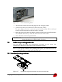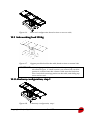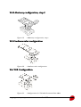
1
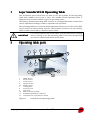
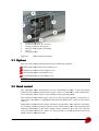
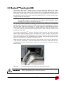
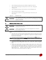
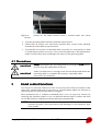
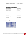
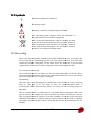
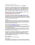
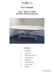
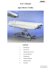
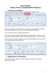
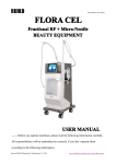
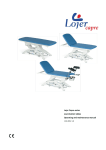
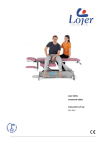
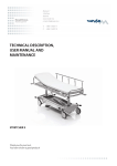
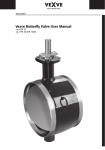
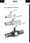
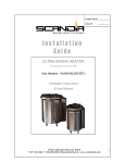
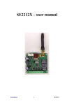
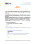
Lojer SCANDIATM SC330
SC330 Operating Table
User manual
R8009 (17.05.2012)
Table of Contents
1
Lojer Scandia SC330 Operating Table ................................................................
............................................................................
............................................ 4
2
Operating table parts ................................................................
................................................................................................
.......................................................................
....................................... 4
3
2.1
Options ............................................................................................................................. 5
2.2
Hand control .................................................................................................................... 5
2.3
BluetoothTM hand control ( ) ...................................................................................... 7
Safety instructions ................................................................
................................................................................................
............................................................................
............................................ 8
3.1
4
Before first time use ................................................................
................................................................................................
.........................................................................
......................................... 9
4.1
5
Precautions..................................................................................................................... 10
Hand control functions ................................................................
................................................................................................
..................................................................
.................................. 10
5.1
Power ON/StandBy ....................................................................................................... 11
5.2
LED lights and audible signals .................................................................................... 11
5.3
Lock.................................................................................................................................. 12
5.4
Unlock ............................................................................................................................. 12
5.5
Patient orientation ........................................................................................................ 12
5.6
Height .............................................................................................................................. 13
5.7
Incline back section...................................................................................................... 13
5.8
Incline leg section......................................................................................................... 13
5.9
Lateral tilt ........................................................................................................................ 13
5.10
Trendelenburg and anti-Trendelenburg .............................................................. 13
5.11
Zero-position ............................................................................................................. 14
5.12
Slide ( ) ...................................................................................................................... 14
5.13
Moving the operating table ..................................................................................... 14
5.13.1
Locking the direction with the directional wheel ( ).................................... 15
5.13.2
Driving forward and backward ( ) .................................................................... 15
5.14
6
Warning signs .................................................................................................................. 8
Using the foot switch (accessory) .......................................................................... 16
Adjusting the head section ................................................................
............................................................................................
............................................................ 17
6.1
Angle of inclination adjustment for head section .................................................. 18
6.2
Vertical adjustment of head section ......................................................................... 18
7
Attaching operating table sections ................................................................
...............................................................................
............................................... 18
8
Removing operating table sections ................................................................
..............................................................................
.............................................. 19
Copyright © Lojer Oy, 2012
version 1.11
2
9
Charging the battery ................................................................
................................................................................................
.......................................................................
....................................... 19
10 Table top configurations ................................................................
................................................................................................
................................................................ 20
10.1
Standard configurations .......................................................................................... 20
10.2
Safe working load 350 kg ......................................................................................... 21
10.3
Lithotomy configuration, step 1 ............................................................................. 21
10.4
Lithotomy configuration, step 2 ............................................................................. 22
10.5
Cardiovascular configuration ................................................................................. 22
10.6
TUR Configuration .................................................................................................... 22
10.7
Prohibited configurations........................................................................................ 23
11 Limitations in movements ................................................................
.............................................................................................
............................................................. 23
12 Cleaning and disinfection ................................................................
..............................................................................................
.............................................................. 25
12.1
Metal and plastic surfaces ....................................................................................... 25
12.2
Operating table mattresses and straps ................................................................. 25
13 Maintenance ................................................................
................................................................................................
....................................................................................
.................................................... 26
13.1
Monthly tasks ............................................................................................................. 26
13.2
Annual tasks ............................................................................................................... 26
14 Troubleshooting................................................................
................................................................................................
..............................................................................
.............................................. 26
15 Technical data ................................................................
................................................................................................
..................................................................................
.................................................. 29
15.1
Identification plate .................................................................................................... 30
15.2
Symbols ....................................................................................................................... 31
15.3
Recycling ..................................................................................................................... 31
15.4
Standards .................................................................................................................... 32
16 Warranty ................................................................
................................................................................................
...........................................................................................
........................................................... 32
17 Contact information ................................................................
................................................................................................
.......................................................................
....................................... 34
For easy access, The user manual should always be kept close to
the operating table.
Copyright © Lojer Oy, 2012
version 1.11
3
1
Lojer Scandia SC330 Operating Table
This document gives instructions on how to use the Scandia SC330 Operating
Table with software version 3.0 or later. The Scandia SC330 Operating Table is
designed to be used for human surgery in operating rooms.
The battery-operated operating table consists of reconfigurable table sections that
can be adjusted according to what is required in an operation.
The operating table has various hydraulic adjustment functions for the entire table
top as well as for back and leg sections. The hydraulic functions are operated by
either a cable-connected or a wireless hand control.
For correct and safe use of the table, read all instructions carefully
before starting to use the operating table. Ensure that all operating
persons are familiar with these instructions
IMPORTANT
2
Operating table parts
4
3
2
3
2
1
5
8
7
6
9
11
12
1
2
3
4
5-6
7
8
9
10
11
12
10
Head section
40 cm section
25 cm section
Center section
Hand control
Locking latch
Accessory rail
Floor lock
Main connection panel
Potential equalization conductor
Connection for optional foot switch
Figure 1.
Scandia SC330 Operating Table
Copyright © Lojer Oy, 2012
version 1.11
4
1
2
3
4
5
6
Auxiliary hand control
Computer interface , D-connector
D
Charging indicator LED (green)
Standby switch (Table On/StandBy)
Fuse (3)
Charging socket
Figure 2.
Main connection panel
2.1 Options
You can order the operating table with the following options:
Bluetooth hand control
co
(see chapter 2.3)
Sliding top function (see chapter 5.12)
Directional wheel (see chapter 5.13)
Driving wheel unit (see chapter 5.13)
NOTE! The options are marked with
in this manual.
2.2 Hand control
The operating table movements can be controlled by either of the two hand
controls. The standard hand control (grey covers) is used with a cable connection.
It is connected to the socket in the column of the operating table.
The auxiliary hand control (grey
(
covers) can be used with a cable connection,
connection or
wirelessly if the table is equipped with optional BluetoothTM hand control (blue
covers).
Both hand controls have the same functions and symbols. They operate in parallel,
for example, when pressing a button in one hand control the corresponding LED
indicator illuminates
uminates in the other hand control. However, you can only operate
only one hand control at a time. It is not possible to select functions from both
hand controls simultaneously.
Copyright © Lojer Oy, 2012
version 1.11
5
Both hand controls revert into power saving mode if not used for 1-240 min
(adjustable time with service software).
23
22
24
19
18
21
15
13
20
12
17
10
16
8
14
11
7
9
4
6
2
3
1
1
2
3
4
5
6
7
8
9
10
11
12
13
14
15
16
17
18
19
20
21
22
23
24
5
Power ON/StandBy
Battery full (green LED)
Charging batteries, line power ON (yellow LED)
Battery low (red LED)
BluetoothTM wireless connection (blue LED)
Floor locks locked (green LED)
Floor locks unlocked (yellow LED)
Normal patient orientation
Reverse patient orientation
Slide forward ( optional)
Slide backward ( optional)
Zero-position (initial position of the operating table)
Lateral tilt, patient’s right
Lateral tilt, patient’s left
Table top up
Table top down
Incline leg section downwards
Incline leg section upwards
Incline back section downwards
Incline back section upwards
Anti-Trendelenburg
Trendelenburg
Drive forward or Directional wheel activation ( optional)
Drive backward or Directional wheel activation ( optional)
Figure 3.
Hand controller
Copyright © Lojer Oy, 2012
version 1.11
6
2.3 BluetoothTM hand control ( )
The auxiliary BluetoothTM hand control is located under the hatch in the main
connection panel. It is normally connected to the operating table with a cable.
BluetoothTM hand control has a built-in battery that is charged automatically when
the auxiliary hand control is connected to the operating table with a cable either in
the charging socket of the main connection panel (Fig. 2) or to the socket in the
column of the operating table.
NOTE! The battery of the BluetoothTM hand controller can only be charged when
the Standby switch is turned ON. The yellow LED illuminates when
charging is in progress (see point 3 in Fig. 3)
The auxiliary hand controller is initially paired and only meant for use with the
specific table and will not operate together with any other equipment. To ensure
this, the table and hand controller are paired together: attach Bluetooth hand
control in the cable, turn On/StandBy to Standby and then back On. Then wait for
5 seconds until you see LED signal. Hand control is now ready for wireless use
with the specific table.
To activate the BluetoothTM wireless function, first disconnect the cable from the
handset then hold down the power ON button for a few seconds. The blue LED
starts to flash and is lit when the wireless function is activated. Hand control turns
off, if the connection is not established in 8 seconds. The operating range for the
wireless connection is 5-10 meters in an open space.
Bluetooth hand control revert into power saving mode if not used for 30 minutes.
If the wireless BluetoothTM connection between the hand set and table can’t be
established the hand set will power down. You can reactivate it by pressing the
Power button.
Figure 4.
IMPORTANT
Auxiliary hand control in the main connection panel
When placing the hand control in the service hatch, make sure the
cable is not touching the controller buttons.
Copyright © Lojer Oy, 2012
version 1.11
7
3
Safety instructions
IMPORTANT
Ensure that Scandia SC330 operating table is not exposed to
electromagnetic radiation exceeding applicable norms. Portable
and mobile RF communications equipment can affect the operating
table.
IMPORTANT
Use antistatic cushions to ensure discharge of static electric.
IMPORTANT
IMPORTANT
Use grounding cord during all functions to prevent possible
electrostatic discharge.
IMPORTANT
Although mechanically possible, do not use the operating table in
other configurations than those illustrated in this document. See
Section 10 Table top configurations.
IMPORTANT
Check that the table sections are correctly locked in place before
using the table. See Section 7 Attaching operating table sections.
IMPORTANT
When not in use, ensure that the hand control is secured safely to
the head section of the table. This will prevent it from getting
caught between different sections or moving parts of the
operating table as well as other equipment.
IMPORTANT
Make sure before using the adjustment functions that there are no
body parts of the patient or personnel between different sections
or moving parts of the operating table.
IMPORTANT
Pay extra attention to any table top movements downwards,
especially when the column in its lower position.
IMPORTANT
In case of a malfunction, take the operating table immediately out
of use and contact the authorized service personnel.
3.1 Warning signs
Pay attention to the following warning signs attached to the base of the operating
table.
Copyright © Lojer Oy, 2012
version 1.11
8
1
Safe working load 350 kg only in pre-defined configuration (see 10.2)
2
Safe working load 280 kg in normal position on floor locks, 200 kg with
sliding top out
3
Safe working load 250 kg in reverse position, also with sliding top out
4
Safe working load 250 kg on wheels
5
The max load of accessories is 40 kg, and load per one accessory rail
max is 25 kg.
Figure 5.
IMPORTANT
4
Maximum load
Safe working load (SWL) is the maximum allowed load including
the patient, mattresses and accessories. Overloading may result in
tipping of the table.
Before first time use
IMPORTANT
Use the operating table in temperature of +10° C to +40 °C and
humidity of 30 % to 75 %.
IMPORTANT
Let the operating table rest in room temperature for six hours
before taking it into use.
Attach the potential equalization conductor to the socket in the operating table
base.
1. Open the main connection panel hatch and insert the fuse (20A) to the socket
located in the panel. The fuse is supplied in a separate box together with the
hand controls and cables.
2. In the main connection panel, turn the standby switch to the ON position.
NOTE! Turn the standby switch to “StandBy” during cleaning, maintenance or in
case of emergency.
3. Connect the main supply cable to the socket in the main connection panel
and charge the operating table batteries for 10-20 hours before using the
table.
4. Connect the spiral cable to the grey hand control and to the socket in the
column of the operating table (figure 6). Ensure that the connector is attached
in the right way (pins match the holes) and then secure into position by
tightening the nut. Similarly, connect the blue auxilary hand control to the
cable socket in the connection panel (see figure 4).
Copyright © Lojer Oy, 2012
version 1.11
9
Figure 6.
Socket for the hand control cable is located under the center
section
5. Test the operating table functions with the hand control.
6. Check that all castors run and freely and that they rotate freely allowing
movement of the table in any direction°.
7. Test that the accessories of the table work correctly. For instructions on how
to install and use the accessories, refer to the manufacturers’ documentation.
Make sure that they do not endanger the safety of the operating table.
4.1 Precautions
5
IMPORTANT
Always immobilize the operating table by pressing the Lock button
before using the adjustment functions.
IMPORTANT
Make sure that there is enough room around, below and above the
operating table to complete all functions, especially when
accessories are attached.
Hand control functions
You can press only one button at a time. If you press more than one button at the
same time, neither will work. If you press a second button while one function is
operating, the first function will then be stopped.
Each movement has a software-controlled limit. You can stop any motion by
releasing the function button or you can hold the button until it reaches the limit
set for that function, and the movement will stop automatically.
NOTE! Even when the Power LED of the hand control is off, the table uses a small
amount of power. This may lead to full discharge of the batteries after
some weeks.
Copyright © Lojer Oy, 2012
version 1.11
10
5.1 Power ON/StandBy
Press the ON/StandBy button in the hand control to activate the operating table.
During start-up phase, three LEDs are flashing as a string, and all functions are
disabled.
Green LEDs illuminate beside the ON/StandBy button as well as in the Lock and
the Patient orientation buttons.
NOTE! The system switches off power if you do not use any function for 1-240
minutes (time adjustable). Reactivate the operating table by pressing ON
button in either of the hand controls.
Turn off power by pressing the ON/StandBy button in the hand control.
IMPORTANT
Turning off power using the ON/StandBy
ON/StandBy button stops all
movements of the table. You can press it also in case you need to
stop a function quickly.
5.2 LED lights and audible signals
The battery indicator LEDs are located at the bottom of the hand control, beside
the ON/StandBy button (see Figure 3 Hand control).
Table 1.
Battery indicator LEDs
Colour
Light
Explanation
Green
Continuous
Battery has sufficient charge for use
Slow flashing
Dropped battery capacity, sufficient to carry
out the ongoing operation.
Yellow
Continuous
Battery charging ongoing.
Red
Continuous
Battery capacity below critical level. Charge
the battery immediately.
The following indicators relate to the function buttons of the hand control.
Table 2.
Function button LEDs and audible signals
Signal
Explanation
Changing green/yellow LEDs
(lock function)
The table is being locked/unlocked. Please
wait until flashing stops and either of the LEDs
is lit continuously.
Blue LED (BluetoothTM)
The wireless connection between the hand
control and the table is established.
Copyright © Lojer Oy, 2012
version 1.11
11
Signal
Explanation
Yellow (Unlock) LED is
continuously lit and green
(Lock) LED flashes every two
seconds.
Either the directional wheel or driving wheel is
activated (both options)
All three power indicator LEDs
are flashing. Repeating beep
sound during movements.
Internal problem, contact service for
troubleshooting.
Short beep
Indicates that you should pay attention with
the table movements, or the adjustment
function has reached the endpoint, for
example, the leg section has reached the max
angle or table is locked/unlocked.
Double beep
Safety stop of all movements. Communication
problem between hand control and table CPU.
Contact service for troubleshooting.
5.3 Lock
To immobilize the operating table, press the Lock button. The operating table
floor locks come down. The green/yellow LEDs in the Lock and Unlock buttons
start to flash and you can hear and audible short beep.
When the green LED in the Lock button is lit continuously the operating table is
completely immobilized.
NOTE! Do not turn off power while immobilizing is in progress.
NOTE! To ensure safety, only table height adjustment and trendelenburg
functions operate when the table is unlocked.
5.4 Unlock
By pressing the Unlock button in the hand control for 1 second, the floor locks are
disengaged and lift up. The green/yellow LEDs in the Lock
Lock and Unlock buttons
start to flash and you can hear a short audible beep.
The operating table is now on the castors. You can move the operating table when
the yellow LED beside the Unlock button is lit continuously.
NOTE! Do not turn off power while mobilizing is in progress.
5.5 Patient orientation
In the normal patient orientation the patient’s head is positioned towards the
longer end of the operating table base (viewed side on), and in the reverse patient
orientation,
orientation towards the shorter end of the operating table base. The green LED
indicates the orientation in the hand control; on the right for normal and on the
left for reverse patient orientation.
Copyright © Lojer Oy, 2012
version 1.11
12
You can change the orientation into reverse by pressing and holding for 3 seconds
the Reverse patient orientation
orientation button on the left. To change the orientation into
normal patient orientation press and hold for 3 seconds the Normal patient
orientation button on the right. The green LED is lit continuously when the
orientation has been changed.
The table will remain in the selected orientation even after switching off power
from the ON/StandBy button.
NOTE! For safety reasons, the button must be pressed for 3 seconds to activate.
NOTE! The hand control and buttons function the same way, whichever patient
orientation (Normal or Reverse) is selected.
5.6 Height
Adjust the height of the table top level by pressing Table up and Table down
buttons.
5.7 Incline back section
Adjust the inclination of the entire back section by pressing the Incline back
section downwards and Incline back section
section upwards buttons.
The maximum inclination upwards is 70°, and downwards 30°.
5.8 Incline leg section
Adjust the inclination of the entire leg section by pressing the Incline leg
eg section
upwards and Incline leg section downwards buttons.
The maximum inclination of the leg section both upwards and downwards is 90°.
5.9 Lateral tilt
Tilt the entire table level to the right, viewed from the head end, by pressing the
Tilt right button.
Tilt the table level to the left by pressing the Tilt left button. The maximum tilt to
both sides is 17°.
5.10 Trendelenburg and antianti-Trendelenburg
Incline the entire tabletop level towards the head end to the Trendelenburgposition by pressing the Trendelenburg button and to the anti-Trendelenburgposition by pressing the AntiAnti-Trendelenburg
Trendelenburg button.
The maximum inclination to both positions is 30°.
Return the tabletop back to the horizontal position by pressing the ZeroZero-position
button or AntiAnti-Trendelenburg button for Trendelenburg-position and vice versa.
NOTE! The Trendelenburg button inclines always the head end, also when the
orientation is reversed.
Copyright © Lojer Oy, 2012
version 1.11
13
5.11 ZeroZero-position
To return the table back to its initial position, press the ZeroZero-position button.
This function returns the slide of the table top, lateral tilt, trendelenburg and antitrendelenburg positions, and the inclinations of the leg and back sections one by
one to the initial position. Foot and back sections and trendelenburg are driven in
15° steps. The height is adjusted separately from the hand control.
You will hear an audible beep when the operating table has reached the zeroposition within 1-2° tolerance.
Each movement has an individual zero -position function for lateral tilt,
trendelenburg, back section and leg section. When any of the movements reach
the horizontal level, the movement is stopped. To continue the movements,
briefly release the button, press it again and the function will allow further
adjustment.
NOTE! If all sections are not straight and leveled after reaching the zero-position,
the safety sensors of the operating table must be recalibrated. Contact the
authorized service personnel for recalibration.
5.12 Slide ( )
Slide the operating table top in the direction of the standard head end by pressing
the right arrow of the Slide button continuously until the table reaches the
required position.
Similarly, to slide the table top in the direction of the standard foot end press the
left arrow.
arrow
The maximum slide movement is 300 mm.
IMPORTANT
When using the slide, the safe working load is 200 kg in normal
orientation and 250 in reverse position.
NOTE! For safety reasons, some functions do not operate when using the slide
function. For details, see Section 11.
NOTE! Limitations in movements.
NOTE! The direction of the slide function will not change in the Reverse Patient
orientation. The slide moves always towards the standard head end.
5.13 Moving the operating table
The operating table may be equipped with an optional directional wheel function,
or an optional motor-operated driving wheel. Both functions lock the direction of
the operating table to ease transporting along corridors.
IMPORTANT
When on castors, the safe working load for is 250 kg. For maximum
stability, the table must be lowered below 800mm before patient
transfer.
Copyright © Lojer Oy, 2012
version 1.11
14
IMPORTANT
Do not use the operating table for transporting the patient if the
floor is uneven. Max floor angle is ± 2 degrees.
NOTE! For safety reasons, the drive function and the directional wheel do not
function in wireless mode. Use always a hand control attached by cable.
Before moving the operating table,
1. Be sure that the patient is properly secured to the table.
2. Center the patient over the main lift column of the operating table.
3. Lower the table top below 800 mm height.
4. Remove all cables from the table. Check the floor for and remove objects that
may interfere with moving the table, such as power cords or table
accessories.
5. Have at least one person at each end of the table.
5.13.1
Locking the direction with the directional wheel ( )
NOTE! The driving wheel replaces the function of the direction lock castor.
NOTE! The different table top functions will not work when the directional wheel
is activated.
1. Press either of the arrow buttons at the top of the hand control for few
seconds to activate the directional wheel. The Unlock LED is continuously lit
and Lock LED flashes every two seconds when the wheel is activated.
The directional wheel comes down and you can move the table straight
forward and backward manually. When directional wheel is activated, moving
the table sideways is difficult and thus not recommended.
2. To deactivate the direction locking, press the Unlock button on the hand
control or release the movement button for about 7 seconds.
5.13.2
Driving forward and backward ( )
NOTE! The adjusting functions of the hand control (except up/down and
trendelenburg) will not work when the drive function is on.
NOTE! The drive function does not work in wireless mode, or if main power
cable is attached for battery charging.
1. Go stand at the head end of the operating table.
2. If the operating table is in immobilized position, press the Unlock button.
3. Attach the hand control to the accessory rail on your right hand side (see
figure 7).
4. Press shortly either of the arrows at the top of the hand control. You’ll hear a
double beeb. In a few seconds the driving wheel comes down and touches
the floor. Unlock LED is continuously lit and Lock LED flashes every two
seconds when the wheel is activated.
Copyright © Lojer Oy, 2012
version 1.11
15
5. Press shortly the arrow pointing forward at the top of the hand control to
drive the operating table away from you. Press shortly the arrow pointing
backward to drive the operating table to the opposite direction. You will hear
a double-beep before the operating table starts to move. The driving wheel
has a so called soft start: the operating table moves first slowly and then
faster.
For adjusting the speed of the driving wheel, contact the authorized service
personnel.
Figure 7.
Driving the operating table
6. To stop the operating table, release the button.
The operating table slows down smoothly and stops.
To deactivate the drive function, press the Unlock button or release the
movement button for about 7 seconds.
NOTE! The logic of the arrow buttons is reversed when attaching the hand
control to the accessory rail of the head section on your left hand side
NOTE! If the power of the table battery falls below the critical level (the red LED
above the battery symbol illuminates in the hand control), the system
automatically stops the drive function and lifts the driving wheel up. The
castors of the operating table operate normally, and you can move the
table manually. Recharge the table batteries immediately.
NOTE! When using the drive function, the table may also be stopped by pushing
the Power ON/StandBy
ON/StandBy button (emergency stop).
5.14 Using the foot switch (accessory)
The foot switch is an accessory. The footswitch functions include:
Trendelenburg and anti-Trendelenburg
Left and right lateral tilt
Table up and down
Copyright © Lojer Oy, 2012
version 1.11
16
1
2
3
Figure 8.
Trendelenburg and anti-Trendelenburg
anti
Lateral tilt
Table up and down
Footswitch
The footswitch enables procedures where the surgeon is normally seated at the
short end of the table. It is possible to change the footswitch functions and the
pedal positioning with Lojer maintenance software. Contact service for changing
the setup. To connect the foot switch remove the connector cover and attach the
footswitch connector to the socket at the leg end of the table.
Figure 9.
6
Attaching the foot switch
Adjusting the head section
A
B
Figure 10.
Head section
Copyright © Lojer Oy, 2012
version 1.11
17
6.1 Angle of inclination adjustment for head section
1. Push the shackle (A) upwards
2. Set the head section to the desired inclination
3. Release the shackle to lock in place
6.2 Vertical adjustment of head section
4. Turn the locking handle (B) anti-clockwise to release the head plate
5. Move the head plate up or down to the required angle
6. Turn the handle (B) clockwise to lock in place
7. Check the angle of inclination and adjust if necessary, as described in
“Adjustment of angle of inclination”, e.g. Set the head plate parallel with the
back section.
7
Attaching operating table sections
The sections are locked to each other with a simple locking mechanism.
1. Take a firm grip of the section.
2. Align the pins with the holes
Figure 11.
Attaching the table section
3. Insert the section by pushing evenly so that the pins engage at the same time.
4. To lock the section in place snap the latches on both sides into place If visible
red signs are visible the latch is not locked.
Figure 12.
Latches
Copyright © Lojer Oy, 2012
version 1.11
18
5. Check that the section is firmly attached by pulling it.
IMPORTANT
8
Open latches indicate that the sections are not fully engaged and
may release unintentionally during the operation (patient safety
risk). Red marks must NOT be visible.
Removing operating table sections
1. On each side, raise the latch (A) until it reaches its upper position. Hold it.
2. Grasp the section to be removed with both hands and pull evenly in the
longitudinal direction of the table top. (This task will be easier if the section is
raised slightly).
A
Figure 13.
Opening latches
NOTE! To ease of section removal, best results are achieved by applying even
and gentle pulling force in the longitudinal direction.
9
Charging the battery
It is recommended that you charge the battery daily after use. In normal use the
battery lasts approximately one week. However, charging of an empty battery can
take ten to twenty hours depending on the battery voltage.
IMPORTANT
IMPORTANT
No person is not allowed to lie on the operating table during
charging.
Be careful not to let any liquid enter the main connection panel.
1. Immobilize the operating table by pressing the Lock button.
2. Open the hatch of the main connection panel at the base of the operating
table.
Copyright © Lojer Oy, 2012
version 1.11
19
Figure 14.
Main connection panel
3. Take the main cable and insert the plug into the charging socket.
4. Connect the other end of the main cable to the wall socket.
The green light in the main connection panel and the yellow LED in the hand
control should illuminate to indicate battery charging.
5. When the green LED above the battery symbol in the hand control illuminates
This indicates the battery is now full. Disconnect the main cable.
6. Close the main connection panel hatch.
IMPORTANT! Batteries should be changed every 3 years or when
charge/discharge cycle drops below 6-8 hours.
10
Table top configurations
You can change the table top configuration according to your needs. The
configurations allowed are described in the following sections.
NOTE! In the normal configuration without accessories, the system prevents the
most typical collisions of operating table parts, provided there are no
obstacles above or underneath the table top.
10.1 Standard configurations
Figure 15.
Standard configuration (head section on normal side)
Copyright © Lojer Oy, 2012
version 1.11
20
Figure 16.
Reversed configuration (head section on reverse side)
10.2 Safe working load 350 kg
Figure 17.
Biggest possible load for the table, head section on normal side
IMPORTANT! SWL 350 kg is possible only with the table top configuration
decribed in Figure 17. Head section is on normal side, and the
patient is centered over the column. Table must be locked on
floor locks before moving patient on the table, and sliding top
must not be used.
10.3 Lithotomy configuration, step 1
Figure 18.
Lithotomy configuration, step 1
Copyright © Lojer Oy, 2012
version 1.11
21
10.4 Lithotomy configuration, step 2
Figure 19.
Lithotomy configuration, step 2
10.5 Cardiovascular configuration
Figure 20.
Cardiovascular configuration
10.6 TUR Configuration
Figure 21.
Configuration for TUR with Extension Plate 60150
Copyright © Lojer Oy, 2012
version 1.11
22
10.7 Prohibited configurations
11
IMPORTANT
Using the table in following configurations increase the risk of
table instability. With the increased risk of accident or injury to the
patient and persons in the vicinity of the equipment, these
configurations are considered unstable and are therefore
prohibited.
Figure 22.
Prohibited configurations, example 1 (head section on reverse side).
Figure 23.
Prohibited configurations, example 2 (head section on normal side)
Limitations in movements
The operating table system software controls certain functions and prevents
movements beyond the range specified in the following table. You cannot
override the limits with the hand control.
IMPORTANT
In movements other than specified in the table, and when using
the operating table with a non-standard configuration, make sure
that the operating table parts do not collide with the floor, walls or
other obstacles.
Copyright © Lojer Oy, 2012
version 1.11
23
The first row specifies the normal minimum or maximum position of each
function. The following rows describe the minimum and maximum positions in
special situations.
Function
Position
Situation
Table height
650 mm
Normal min. height
920 mm
Min. height when leg section inclination > 65°
downwards
-30°
Normal max. inclination
-15°
Max. inclination when lateral tilt >±5°
-13°
Max. inclination when back section inclination -20°
-30°
Normal max. inclination
-15°
Max. inclination when lateral tilt > ±5°
-13°
Max. inclination when leg section inclination > 55°
downwards
Disabled
Leg section inclination 65°downwards
± 17°
Normal max. tilt
± 5°
Max. tilt when Trendelenburg or antiTrendelenburg >20°
Disabled
Leg section inclination > 65° downwards
-90°
Normal max. inclination downwards
-65°
Max. inclination when table height < 920 mm
300 mm
Normal slide towards the standard head end
Disabled
Trendelenburg or anti-Trendelenburg > 13°
Trendelenburg
AntiTrendelenburg
Lateral tilt
Leg section
Sliding top ( )
Leg section inclination > 1°downwards
Copyright © Lojer Oy, 2012
version 1.11
24
12
Cleaning and disinfection
IMPORTANT
Switch power switch to StandBy before cleaning and detach the
main power cable.
IMPORTANT
Do not use shower, high-pressure water guns or similar for
cleaning. Under no circumstances should steam or extremely hot
water be used to disinfect or clean the table.
IMPORTANT
Do not clean the operating table in room with high temperature
and air humidity. It can cause malfunctions in the hydraulics
system.
IMPORTANT
Do not let fluids in the main connection panel or inner parts of the
operating table.
IMPORTANT
IMPORTANT
Do not use solvents for cleaning.
Dry all surfaces thoroughly after cleaning or disinfection.
12.1 Metal and plastic surfaces
Clean the metal and plastic surfaces and the hand controls with a damp cloth and
weak alkaline cleaning fluid. Use small brush for corners and other difficult spots.
Rinse with clean water and dry carefully after cleaning.
Use disinfectant (e.g. 70% methylated spirit) and follow the disinfectant
manufacturer’s instructions for use. Let dry by evaporation in room temperature.
NOTE! All surfaces must be dry before switching the operating table ON.
12.2 Operating table mattresses and straps
Remove the table top pads before cleaning. Wash mattresses and straps carefully
with warm water (50°) and neutral (pH7) detergent. Rinse with clean water, wipe
them dry and leave to dry in room temperature. Use small brush for corners and
other difficult spots.
Spray a disinfectant (70% methylated spirit or 1000-5000 mg/ltr solution of
hypochlorite in water) directly onto the pads. Rinse with clean water. Wipe clean
with absorbent soft paper and let dry by evaporation in room temperature.
If necessary brush the Velcro bands, the pads and the tabletop with a non-metallic
brush.
NOTE! Do not let hypochlorite solution to come into contact with metallic parts.
Long-term contact with mattresses may damage them.
NOTE! If non-Lojer pads are used, refer to the table pad manufacturer’s
instructions on the use of disinfectants with table pads.
Copyright © Lojer Oy, 2012
version 1.11
25
Check mattresses regularly for damages and wearing. Replace mattress with
damaged surface with new one immediately. Do not storage mattresses in close
distance with sharp edges, and not leave them to high temperate. The mattresses
must not be exposed to ozone.
13
Maintenance
13.1 Monthly tasks
Carry out the following checks and maintenance tasks once a month. Keep record
of the checks and the results.
Check all functions and movements of the table top one by one by adjusting
them to their end position and back.
Remove all sections. Clean all dowels pins, holes and latches. Lubricate them
with thin machine or instrument oil. Check that sections lock properly.
Check that the castors run freely and turn 360°.
Check that the cables and plugs are intact and that the connections function
correctly.
13.2 Annual tasks
The operating table should be serviced at least once a year by an authorized
service person. The annual maintenance is instructed in a separate maintenance
manual.
14
Troubleshooting
Symptom
Failure
Action
None of the hand
control functions
operate and no
leds are visible.
The cable of the standard
hand control is not
connected.
Check the cable connections
and that the cable is intact.
The battery of the auxiliary
(Bluetooth) hand control is
empty.
Charge the battery by
connecting the auxiliary hand
control to the operating table
with a cable. In the
meanwhile, use the standard
hand control.
Stand-by switch of the
table (under the hatch) is
turned StandBy
Turn the switch ON
Copyright © Lojer Oy, 2012
version 1.11
26
Symptom
Failure
Action
The batteries of the
operating table are empty.
Connect the main cable to
the charging socket and
charge the batteries.
The hand control has
damaged.
Contact service. In the
meanwhile, use the other
hand control
Bluetooth control
cannot be turned
on – only leds flash
briefly
The hand control battery is Connect the cable, turn
empty
Standby switch to ON and let
the battery be charged for 1-2
hours.
Foot pedal do not
function.
Cable is not connected
properly.
Connect the cable as
instructed.
Foot pedal functions have
not been set up with
maintenance software.
Contact service to program
the functions.
The hand control is
turned ON, but
only up/down and
trendelenburg do
operate.
Table is unlocked.
Press table locking button to
enable the movements.
Drive motor does
not function
Table is locked.
Press table unlocking button
to enable the movements.
The power cable is
attached to the table.
Disconnect the power cable.
All power
indication leds in
hand control are
flashing
simultaneously
Table is locked, and you
hear beep sounds during
table movements.
Reset the alarm by setting
main switch to Standby and
back On.
Charging led
(yellow) remains
On even after
power plug has
been removed
Battery voltage remains
high after charging.
Copyright © Lojer Oy, 2012
If alarm still continues, angle
position sensors provide
false values, contact service
immediately.
version 1.11
No negative implications. Led
turns off after using the table
for a while.
27
Symptom
Failure
Action
Table is difficult to
move sideways
Directional wheel or drive
motor is being activated.
Press table unlock button
once to deactivate the motor.
Some movements
do not operate
One or several movements
have reached the end
position (beeb sound) or
the table controller
prevents the movement
due to the risk of collision.
Press 0-position button for
few seconds to release the
blocked functions.
Sliding top is not in the
home position and safety
sensors are blocking some
movements (see conflict
table, ch apter 11) .
Move sliding top to the home
position and then move the
other functions.
Safety stop due to
communication failure.
If the problem is repeated,
take table to service.
During movement
table is stopped
with double beep.
Check whether the aux hand
control works perfectly? If
yes, replace main hand
control with aux hand
control. If the problem is
repeated, the spiral cable is
most likely damaged.
Safety stop due to
communication failure
when using Bluetooth
hand control.
Use Bluetooth closer to table
and make sure there are no
obstacles (even staff)
between table and signal.
If the problem is repeated,
take table to the service.
For ordering spare parts, contact Your local dealer or Lojer Service (see 17 Contact
Information).
Copyright © Lojer Oy, 2012
version 1.11
28
15
Technical data
Dimensions and weights
Overall length
2070 mm
Width of table top
550 mm
Width over accessory rails
605 mm
Weight of the operating table
260 kg
Safe working
orientation
load
(SWL)
in
normal 280/350 kg
Safe working
orientation
load
(SWL)
in
reverse 250 kg
Adjustment ranges
Height (without pads)
650-1010 mm
Trendelenburg/Anti-Trendelenburg
30° / 30°
Lateral tilt (right/left)
17° / 17°
Back section (up/down)
70° / 35°
Head section
+26°/-58°, can be raised 135
mm
Leg section (up/down)
90° / 90°
Longitudinal slide (optional)
300 mm
Speed of Driving wheel unit (option)
Max 0.7-0.8 m/s (full load)
Electrical data
Main power supply (EU)
230 V~; 50 Hz
Maximum current consumption
1,5 A x 230 V
Protection system
IP 24
Protection type
B
Protection class
I
Copyright © Lojer Oy, 2012
version 1.11
29
Internal power supply (main batteries)
2 x 12VDC connected in
series, total 24VDC, 20 Ah
Operating rate
2,5 min / 10 min
Ambient conditions for transport and storage
Temperature, transport
- 10° C to + 40° C
Temperature, storage
+ 10° C to + 40° C
Relative air humidity
30 % to 75 %
Air pressure
700 hPa to 1060 hPa
Ambient conditions for operation
Temperature
+10° C to + 40° C
Relative air humidity
30 % to 75 %
Air pressure
700 hPa to 1060 hPa
15.1 Identification plate
The identification is located inside the hatch of the main connection panel.
Copyright © Lojer Oy, 2012
version 1.11
30
15.2 Symbols
Potential equalization conductor
Protection type B
Attention, consult accompanying document(s).
The operating table complies with
with the demands in
directive 93/42 EEC for medical equipment.
The
crossed-out wheeled-bin
bin symbol reminds you that
in the EU all electrical and electronic products, batteries,
and accumulators must be taken to separate collection
at the end of their working life. Do not dispose of these
products as unsorted municipal waste.
15.3 Recycling
After Lojer Operating tables and their parts
parts have fulfilled their use, recycling is the
next critical step in completing the life cycle. The metal content is more than 90%
of the total weight of the table, which makes the table among the most recycled
industrial products. Recycling of the table must
must be done by a professional
organization, and it must never be disposed as unsorted municipal waste.
Pre-Treatment
Treatment and storage
First of all the batteries are taken off. Then the dismantler takes off all oils. These
environmentally hazardous materials are collected and later on sent to specialised
recovery companies for recovery or disposal.
Dismantling
The next step is the dismantling of components and systems in order to market
them as used part or to use them as basis for remanufactured parts. If
economically
ically viable, materials like plastics are taken off for recycling purposes.
Shredder
The pre-treated
treated hulks are delivered to a shredder which segregates them into
pieces and sorts the output into various fractions for further recycling or recovery.
The segregated
egregated material fractions from the shredder are further processed with
different technologies to obtain material fractions which can be used as valuable
secondary raw material that reduces drastically the amount of remaining waste for
landfill.
Copyright © Lojer Oy, 2012
version 1.11
31
15.4 Standards
Standards
The Scandia Operating Table SC330 complies with the following standards:
IEC 6060160601-1 Medical electrical equipment. General requirements for safety and
essential performance
IEC 60601MEDICAL ELECTRICAL EQUIPMENT60601-2-46
REQUIREMENTS FOR THE SAFETY OF OPERATING TABLES
PARTICULAR
IEC 6060160601-1-2 MEDICAL ELECTRICAL EQUIPMENT PART 1-2: GENERAL
REQUIREMENTS FOR SAFETY - COLLATERAL STANDARD: ELECTROMAGNETIC
COMPATIBILITY - REQUIREMENTS AND TESTS
LOJER SCANDIA SC330 is class I product (European Council Directive 93/42/EEC
Class I). Lojer Oy is an ISO9001 certified company with environmental
management system.
16
Warranty
Thank you for purchasing this quality product from Lojer. Our products are
developed to meet high standards in both quality and technology. To further
ensure quality, we grant you, the final customer, a warranty on our products in
accordance with the following conditions.
The Lojer product is warranted for the period of twenty-four (24) months from the
original date of purchase, against defective materials and workmanship. Batteries
and mattresses have twelve (12) month warranty.
In the event that warranty service is required, you should return the product to the
dealer from whom it was purchased. In case of difficulty, details of the local
dealers are available at www.lojer.com. You may also contact the service center in
Finland (email: [email protected]).
International warranty conditions
1. The warranty is only valid if, when warranty service is required, the warranty
demand is presented with the original invoice or sales slip or confirmation,
and the serial number on the product has not been defaced.
2. Lojer’s obligations are limited to the repair or, at its discretion, replacement
of the product or the defective part. For this, the customer is responsible for
the dispatch and insurance of the product. The transport and insurance costs
shall be borne by the customer. Lojer shall assume the costs for the materials
/ spare parts and the labor costs as required, as well as the return postage to
the sender.
3. In case of warranty repairs, they must be carried out by Authorized Lojer
Dealers. No re-imbursement will be made for repairs carried out by non-Lojer
representative and, any such repair work and damage to the products caused
by such repair work will not be covered by this warranty.
4. This product is not considered to be defective in materials nor workmanship
by reason that it requires adaptation in order to conform to national or local
technical or safety standards in force in any country other than the one for
which the product was originally designed and manufactured. This warranty
Copyright © Lojer Oy, 2012
version 1.11
32
will not cover, and no re-imbursement will be made for such adaptation or
any damage which may result.
5. This warranty covers none of the following:
A. Periodic check ups, maintenance and repair or replacement of parts due
to normal wear and tear (such as upholsteries, ropes or reduced capacity
of accumulators)
B. Cost relating to transport, removal or installation of the product.
C. Misuse, including the failure to use this product for its normal purposes
or incorrect installation.
D. Damage caused by lightning, water, fire, acts of god, war, public
disturbances, incorrect mains voltage or any other cause beyond the
control of Lojer.
E. Spillage of chemicals or liquid or use of any other hazardous or noninstructed substances, which may affect the product.
F. Minor defects or deviations from the product specifications, that are
immaterial or negligible as regards to the value or the functioning of the
product
The guarantee will become void
if a Lojer product is equipped or used with parts that have not been approved
by Lojer for the product in question.
if someone other than a person authorised by Lojer has serviced/repaired or
otherwise modified the device and these measures have caused a fault in the
product.
if the product is cleaned with cleaning agents other than those specified in the
operating manual, or if the product is put into direct contact with agents other
than those specified in the manual.
if the regular maintenance has not been performed.
Proceeding in a warranty case
The following information is an explanation of what you must do in the case of a
warranty claim. Should, contrary to expectation, your Lojer product be defective,
please contact your Lojer dealer first. There our employees will help diagnose
defects and malfunctions. They are often capable of eliminating the malfunction
over the phone.
Please always have the following information ready before calling the dealer or
Lojer Service:
Your name, address, post code and a telephone number at which you can be
reached
the model designation, the article code and the serial number of the product
the date of purchase
Copyright © Lojer Oy, 2012
version 1.11
33
a brief description of the problem, possibly including photographs.
You will find the information from the type plate located in the column of the
operating table. The maintenance of the operating table and the list of spare parts
are described in a separate maintenance manual.
17
Contact information
Manufacturer
Lojer Oy
Putajantie 42 / P.O. Box 54
FI-38201 SASTAMALA, FINLAND
Tel. +358 10 830 6700, Fax +358 10 830 6702
www.lojer.com
Lojer Service
Service,
ice, Finland
Tel. +358 10 830 6750
Email: [email protected]
Copyright © Lojer Oy, 2012
version 1.11
34