1
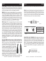
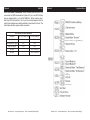
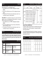
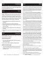
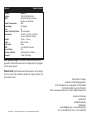
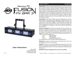
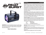
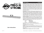
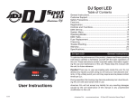
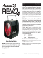
Revo 4 General Information
Unpacking: Thank you for purchasing the Revo 4 by American DJ®.
Every Revo 4 has been thoroughly tested and has been shipped in
perfect operating condition. Carefully check the shipping carton for
damage that may have occurred during shipping. If the carton appears
to be damaged, carefully inspect your fixture for any damage and be
sure all equipment necessary to operate the unit has arrived intact. In
the event damage has been found or parts are missing, please contact
our toll free customer support number for further instructions. Please
do not return this unit to your dealer without contacting customer support first.
Introduction: The Revo 4 can be a four or 256 channel, DMX intelligent LED fixture. The fixture has three different operating modes;
sound-active, show mode, DMX controlled. The Revo 4 has twelve
shows to choose from. The unit can be used as a stand alone unit or in
a master/slave configuration. For best results use fog or special effects
smoke to enhance the beams projections.
Customer Support: American DJ® provides a toll free customer
support line, to provide help and to answer any question should you
encounter problems during your set up or initial operation. You may
also visit us on the web at www.americandj.com for any comments or
suggestions. Service Hours are Monday through Friday 8:00 a.m. to
4:30 p.m. Pacific Standard Time.
Voice:
(800) 322-6337
Fax: (323) 582-2941
E-mail: [email protected]
To purchase parts online visit http://parts.americandj.com
User Instructions
WARNING! Due to the magnifying type lens, please keep
the lens out of contact with direct sunlight. Direct sunlight
can cause heat to build up inside of the unit, which will
seriously damage unit.
Rev. 6/11
Warning! To prevent or reduce the risk of electrical shock or fire, do
not expose this unit to rain or moisture.
Warning! This may cause severe eye damage. Avoid looking directly
into the light source at all times!
American DJ® - www.americandj.com - Revo 4 Instruction Manual Page 2
Revo 4 General Instructions
To optimize the performance of this product, please read these
operating instructions carefully to familiarize yourself with the basic
operations of this unit. These instructions contain important safety
information regarding the use and maintenance of this unit. Please
keep this manual with the unit, for future reference.
Revo 4 Features
• DMX-512 Protocol Compatible (Four or 256 DMX Channels)
• RGB + White
• 3 Operating Modes - Show Mode; Sound Active; DMX Controlled
• Stand Alone or Master/Slave Configuration
• Internal Microphone
• Digital Display for Address and Function Setting
• UC3 Controller (Not Included)
• 12 Show Modes
Revo 4
Warranty Registration
The Revo 4 carries a 3 year (1095 days) limited warranty. Please fill
out the enclosed warranty card to validate your purchase and warranty. You may also register your product online at www. americandj.
com. All returned service items whether under warranty or not, must
be freight pre-paid and accompany a return authorization (R.A.) number. If the unit is under warranty you must provide a copy of your
proof of purchase invoice. Please contact American DJ® customer
support for a R.A. number.
Revo 4 Handling Precautions
Caution! There are no user serviceable parts inside this unit. Do not
attempt any repairs yourself, doing so will void your manufactures warranty. In the unlikely event your unit may require service please contact
American DJ®.
American DJ® will not accept any liability for any resulting damages
caused by the non-observance of this manual or any unauthorized
modification to this unit.
American DJ® - www.americandj.com - Revo 4 Instruction Manual Page 3
Revo 4 Safety Precautions
For Your Own Personal Safety, Please Read and Understand This
Manual Completely Before You Attempt To Install Or Operate
This Unit!
•To reduce the risk of electrical shock or fire, do not expose this unit rain or moisture
•Do not spill water or other liquids into or on to your unit.
•Do not attempt to operate this unit if the power cord has been
frayed or broken.
•Do not attempt to remove or break off the ground prong from the electrical cord. This prong is used to reduce the risk of electrical shock and fire in case of an internal short.
•Disconnect from main power before making any type of connection.
• Do not remove the cover under any conditions. There are no user serviceable parts inside.
•Never operate this unit when it’s cover is removed.
•Always be sure to mount this unit in an area that will allow proper ventilation. Allow about 6” (15cm) between this device and a wall.
•Do not attempt to operate this unit, if it becomes damaged.
•This unit is intended for indoor use only, use of this product outdoors voids all warranties.
•Always mount this unit in safe and stable matter.
•Power-supply cords should be routed so that they are not likely to be walked on or pinched by items placed upon or against them, paying particular attention to cords at plugs, convenience recep-
tacles, and the point where they exit from the appliance.
• Cleaning -The fixture should be cleaned only as recommended by the manufacturer. See page 15 for cleaning details.
•Heat -This fixture should be situated away from heat sources such
as radiators, heat registers, stoves, or other appliances (including
amplifiers) that produce heat.
•The fixture should be serviced by qualified service personnel when:
A. Objects have fallen, or liquid has been spilled into the appliance.
B. The appliance has been exposed to rain or water.
C. The appliance does not appear to operate normally or exhibits a
marked change in performance.
American DJ® - www.americandj.com - Revo 4 Instruction Manual Page 4
REMOTE
CONTROL
INPUT
SOUND
Revo 4
Set Up
OUTPUT
1
2
3
American DJ® - www.americandj.com - Revo 4 Instruction Manual Page 5
SOUND
Set Up
POWER
cables. Do not use the ground lug on the XLR connector. Do not conDMX512
nect the cable’s DMX+,DMX-,COMMON
shield
conductor to the ground lug or allow the shield
conductor to come in contact with the XLR’s outer casing. Grounding
the shield could cause a short circuit and erratic behavior.
COMMON
DMX512 OUT
3-PIN XLR
1
2
DMX +
3
DMX -
3
1
2
DMX512 IN
3-PIN XLR
3
Figure 2
XLR Female Socket
XLR Male Socket
1 Ground
2 Cold
2 Cold
REMOTE
CONTROL
INPUT
SOUND
INPUT
OUTPUT
1 Ground
2
Termination re
avoids signal
and interferenc
to connect a DM
120 Ohm 1/4 W
and PIN 3 (DM
XLR Pin Configuration
Pin 1 = Ground
Pin REMOTE
2 = Data Compliment (negative)
SOUND
3 Hot
1
3 Hot
CONTROL
INPUT
INPUT
OUTPUT
Pin 3 = Data True (positive)
Figure 3
Special Note: Line Termination. When longer runs of cable are
used, you may need to use a terminator on the last unit to avoid erratic
behavior. A terminator is a 110-120 ohm 1/4 watt resistor which is connected between pins 2 and 3 of a male XLR connector (DATA + and
DATA -). This unit is inserted in the female XLR connector of the last
unit in your daisy chain to terminate the line. Using a cable terminator
(ADJ part number Z-DMX/T) will decrease the possibilities of erratic
behavior.
POWER
Data Cable (DMX Cable) Requirements (For DMX and Master/Slave
Operation): The Revo 4 can be controlled via DMX-512
protocol. The
DMX512
DMX+,DMX-,COMMON
Revo 4 can be a four or 256 channel DMX unit.
The DMX address
is set electronically using the controls on the rear
panel of the unit. Your unit and your DMX controller require a approved DMX-512 110 Ohm Data
cable for data input and data output (Figure 1). We
COMMON
recommend Accu-Cable DMX cables. If you are
DMX +
DMX512
OUT
making your own cables, be sure to use standard
3-PIN XLR
DMX 110-120 Ohm shielded cable (This cable may be
purchased at almost all professional sound and
Figure 1
lighting stores). Your cables should be made with
a male and female XLR connector on either end of the cable. Also
OUTPUT
POWER
tocol used by most lighting and controller manufactures as a form of
communication between intelligent fixtures and controllers. A DMX
controller sends DMX data instructions from the controller to the fixture. DMX data is sent as serial data that travels from fixture to fixture
via the DATA “IN” and DATA “OUT” XLR terminals located on all DMX
fixtures (most controllers only have a DATA “OUT” terminal).
INPUT
INPUT
Notice: Be sure to follow figures two and three when making your own
DMX-512: DMX is short for Digital Multiplex. This is a universal pro-
REMOTE
CONTROL
INPUT
REMOTE
CONTROL
INPUT
SOUND
remember that DMX cable must be daisy chained and cannot be split.
age switch, which will auto sense the voltage when it is plugged into
the power source. With this switch there is no need to worry about the
correct power voltage, this unit can be plugged in anywhere.
SOUND
OUTPUT
Revo 4
Power Supply: The American DJ® Revo 4 contains a automatic volt-
DMX Linking: DMX is a language allowing all makes and models
of different manufactures to be linked together and operate from a
single controller, as long as all fixtures and the controller are DMX
compliant. To ensure proper DMX data transmission, when using
several DMX fixtures try to use the shortest cable path possible. The
order in which fixtures are connected in a DMX line does not influence
the DMX addressing. For example; a fixture assigned a DMX address
of 1 may be placed anywhere in a DMX line, at the beginning, at the
end, or anywhere in the middle. Therefore, the first fixture controlled
by the controller could be the last fixture in the chain. When a fixture
is assigned a DMX address of 1, the DMX controller knows to send
DATA assigned to address 1 to that unit, no matter where it is located
in the DMX chain.
INPUT
POWER
3
1
2
DMX512 IN
3-PIN XLR
3
1
2
POWER
Termination reduces signal errors and
avoids signal transmission problems
and interference. It is always advisable
to connect a DMX terminal, (Resistance
120 Ohm 1/4 W) between PIN 2 (DMX-)
and PIN 3 (DMX +) of the last fixture.
Figure 4
American DJ® - www.americandj.com - Revo 4 Instruction Manual Page 6
Revo 4
Set Up
Revo 4
System Menu
5-Pin XLR DMX Connectors. Some manufactures use 5-pin XLR
connectors for DATA transmission in place of 3-pin. 5-pin XLR fixtures
may be implemented in a 3-pin XLR DMX line. When inserting standard 5-pin XLR connectors in to a 3-pin line a cable adaptor must be
used, these adaptors are readily available at most electric stores. The
chart below details a proper cable conversion.
3-Pin XLR to 5-Pin XLR Conversion
Conductor
3-Pin XLR Female (Out)
5-Pin XLR Male (In)
Ground/Shield
Pin 1
Pin 1
Data Compliment (- signal)
Pin 2
Pin 2
Data True (+ signal)
Pin 3
Pin 3
Not Used
Pin 4 - Do Not Use
Not Used
Pin 5 - Do Not Use
American DJ® - www.americandj.com - Revo 4 Instruction Manual Page 7
American DJ® - www.americandj.com - Revo 4 Instruction Manual Page 8
Revo 4
System Menu
System Menu: When confirming your setting press ENTER and
then hold MENU for at least 2-3 seconds, or you can wait 1
minute for automatic setup. To exit without making any adjustments press the MENU button.
ADDR - DMX Address Setting.
1. Tap the either the MENU, UP, or DOWN buttons until “ADDR” is
displayed, press ENTER.
2. “1” will now be displayed and flashing. Press the UP or DOWN buttons to find your desired address. Press ENTER to set your desired
DMX address.
NOTE: If after you connect your DMX controller the unit does not
fall into DMX mode, press and hold the MENU button for at least 3
seconds.
CHND - This will let you switch between 4 Channel DMX
mode and 256 Channel DMX mode.
1. Tap the either the MENU button until “CHND” is displayed, press
ENTER. Either “4CH” or “256C” will be displayed
2. Tap the UP or DOWN buttons to choose your desired DMX mode
and press ENTER to confim and exit.
SLND - This will let you set unit as a master or slave in a
master/slave configuration.
1. Tap the either the MENU button until “SLND” is displayed, press
ENTER. “MAST”, “SL 1” or “SL 2” will be displayed.
Revo 4
System Menu
faster.
1. Tap the MENU button until “ShNd” is displayed, press ENTER.
2. “Sh X” will now be displayed, “X” representing a number between
1-12. Programs 1-12 are preset shows, while “Sh 0” is random mode.
Press the UP or DOWN buttons to find your desired show and press
ENTER to confirm.
3. Press ENTER to confirm, and then press and hold the MENU button
for at least 3 seconds.
SOUN - In this mode you can run the unit in sound active
mode
1. Tap the MENU button until “SOUN” is displayed, press ENTER.
2. Either “ON” or “OFF” will now be displayed. Press the UP or DOWN
buttons to select one or the other.
3. When you have made your selection, press the ENTER, and then
press and hold the MENU button for at least 3 seconds to confirm.
BLND - Blackout or Stand by mode.
1. Tap the either the MENU button until “BLND” is displayed, press
ENTER. Either Yes or No will be displayed.
2. To activate Blackout tap the UP or DOWN buttons until Yes is
displayed, press ENTER to confim and exit. The fixture will now be in
Blackout mode. To deactivate Blackout mode, select No and press
Enter.
2. Tap the UP or DOWN buttons until your desired setting is displayed, press ENTER to confim and exit.
LED - With this function the LED display will turn off after
SHND: SH 1 - SH 12 - Show modes 0 - 12
1. Tap the either the MENU button until “LED” is displayed, press
ENTER.
Show Mode can run with or without sound active mode
on. With sound active mode on, the shows will tend to run
American DJ® - www.americandj.com - Revo 4 Instruction Manual Page 9
2 minutes.
2. The display will show either “ON” or “OFF”. Press the UP or DOWN
buttons to select “ON” to keep the LED display on at all times, or
American DJ® - www.americandj.com - Revo 4 Instruction Manual Page 10
Revo 4
System Menu
“OFF” to allow the LED display to turn off after 2 minutes. Press any
button to turn on the LED display again.
3. Press ENTER to confirm and exit.
DISP - This function will reverse the display 180º.
1. Tap the either the MENU button until “DISP” is displayed, press
ENTER.
2. Press the UP button to select “DISP” to activate this function, or
“DSIP” to deactivate this function.
3. Press ENTER to confirm.
TEST - This function will run a self test program.
1. Tap the MENU button until “TEST” is displayed, press ENTER.
2. The fixture will now run a self test.
FHRS - With this function you can display the running time
of the unit.
1. Tap the either the MENU button until “FHRS” is displayed, press
ENTER.
2. The display shows the running time of the unit. Press MENU to
exit.
VER - Use this function to display the Software version of
the unit.
1. Tap the either the MENU button until “VER” is displayed, press
ENTER.
2. The display will show the software version.
American DJ® - www.americandj.com - Revo 4 Instruction Manual Page 11
Revo 4
Operation
Universal DMX Control: This function allows you to use a Elation®
universal DMX-512 controller. A DMX controller allows you to create
unique programs tailored to your individual needs.
1. The Revo 4 has 4 DMX channel mode and a 256 DMX channel mode. To set the channel mode see page 8. See page 14 a for detailed description of the DMX traits.
2. To control your fixture in DMX mode, follow the set-up procedures
on pages 5-7 as well as the set-up specifications that are
included with your DMX controller.
3. Use the controller’s faders to control the various DMX fixture traits.
4. This will allow you to create your own programs.
5. Follow the instruction on page 8 to set the DMX address.
6. For longer cable runs (more than a 100 feet) use a terminator on the last fixture.
7. For help operating in DMX mode consult the manual included with your DMX controller.
Master-Slave Operation: This function will allow you to link up to
16 units together and operate without a controller. In Master-Slave
operation one unit will act as the controlling unit and the others will
react to the controlling units programs. Any unit can act as a Master
or as a Slave.
1. Using standard XLR microphone cables, daisy chain your units together via the XLR connector on the rear of the units. Remem-
ber the Male XLR connector is the input and the Female XLR connector is the output. The first unit in the chain (master) will use the female XLR connector only - The last unit in the chain will use the male XLR connector only. For longer cable runs we suggest a terminator at the last fixture.
2. On the Master unit find your desired show or choose sound act- tive mode and set that by pressiing the ENTER button.
3. On the slave units tap the MENU button until “SLND” is display-
ed, and Press ENTER.
4. The slave units will now follow the Master unit.
5. The optional UC3 Controller (not included) may be used to con-
trol different functions including blackout.
American DJ® - www.americandj.com - Revo 4 Instruction Manual Page 12
Revo 4
Operation
Revo 4
Traits & Values - 4 Channel DMX Mode
Sound Active Mode: This mode allows a single unit or several units
linked together, to run to the beat of the music.
1. Tap the MENU button until “SOUN” is displayed, and press ENTER.
2. Tap the UP or DOWN buttons until “ON” is displayed and press ENTER.
3. The optional UC3 Controller (not included) may be used to con-
trol different functions including blackout.
Show Mode: This mode allows a single unit or several units linked
together, to run 1 of 12 light shows. For Show Mode to run properly
make sure that Sound Active Mode is off.
1. Tap the MENU button until “SHND” is displayed, and press ENTER.
2. Tap the UP or DOWN buttons until you find your desired show, and press ENTER to confirm.
3. The optional UC3 Controller (not included) may be used to con-
trol different functions including blackout.
Revo 4
Power Cord Daisy Chain
With this feature you can connect the fixtures to one another
using the IEC input and output sockets. The quantity that can be
connected is 20 fixtures maximum. After 20 fixtures you will need
to use a new power outlet. They must be the same fixtures. DO
NOT mix fixtures.
Revo 4
Using 4 Channel DMX Mode:
To project a pattern using Channel 2, the Channel values must
be between 10-99. This also applies to changing the pattern
color using Channel 3.
To run the chases using Channel 2, the Channel 1 values must
be between 100-239. This also applies to controlling the chase
speed using Channel 3.
Revo 4
Traits & Values - 256 Channel DMX Mode
UC3 Control
Blackout Blackout the unit
Function
1. Sound White Strobe
2. Sound Color Strobe
Select Show
(Show 1-12)
Mode
Sound/Strobe
(LED OFF)
Show
(LED ON)
American DJ® - www.americandj.com - Revo 4 Instruction Manual Page 13
American DJ® - www.americandj.com - Revo 4 Instruction Manual Page 14
Revo 4
Fuse Replacement
First unplug the power. The fuse holder is located next to the power
cord. Using a flat-head screw driver unscrew the fuse holder. Remove
the bad fuse and replace with a new one.
Revo 4 Cleaning
Fixture Cleaning: Due to fog residue, smoke, and dust cleaning the
internal and external optical lenses and mirror should be carried out
periodically to optimize light output. Cleaning frequency depends on
the environment in which the fixture operates (I.e. smoke, fog residue,
dust, dew). In heavy club use we recommend cleaning on a monthly
basis. Periodic cleaning will ensure longevity, and crisp output.
1. Use normal glass cleaner and a soft cloth to wipe down the out-
side casing.
2. Use a brush to wipe down the cooling vents and fan grill.
3. Clean the external optics and mirror with glass cleaner and a soft cloth every 20 days.
4. Clean the internal optics with glass cleaner and a soft cloth every 30-60 days.
5. Always be sure to dry all parts completely before plugging the unit back in.
Revo 4 Trouble Shooting
Trouble Shooting: Listed below are a few common problems that
you may encounter, with solutions.
No light output from the unit;
1. Be sure the external fuse has not blown. The fuse is located on the rear panel of the unit.
2.Be sure the fuse holder is completely and properly seated.
Unit does not respond to sound;
1. Low frequencies (bass) should cause the unit to react to sound.
Tapping on the microphone, quiet or high pitched sounds may
not activate the unit.
American DJ® - www.americandj.com - Revo 4 Instruction Manual Page 15
Revo 4 Warranty
MANUFACTURER’S LIMITED WARRANTY
A. American DJ, Inc. hereby warrants, to the original purchaser, American DJ and American
Audio products to be free of manufacturing defects in material and workmanship for a prescribed
period from the date of purchase (see specific warranty period on reverse). This warranty shall be
valid only if the product is purchased within the United States of America, including possessions
and territories. It is the owner’s responsibility to establish the date and place of purchase by acceptable evidence, at the time service is sought.
B.
For warranty service you must obtain a Return Authorization number (RA#) before
sending back the product. Contact American DJ, Inc. Service Department at 800-322-6337. Send
the product only to the American DJ, Inc. factory. All shipping charges must be pre-paid. If the
requested repairs or service (including parts replacement) are within the terms of this warranty,
American DJ, Inc. will pay return shipping charges only to a designated point within the United
States. If the entire instrument is sent, it must be shipped in it’s original package. No accessories
should be shipped with the product. If any accessories are shipped with the product, American DJ,
Inc. shall have no liability whatsoever for loss of or damage to any such accessories, nor for the
safe return thereof.
C. This warranty is void if the serial number has been altered or removed; if the product is
modified in any manner which American DJ, Inc. concludes, after inspection, affects the reliability
of the product; if the product has been repaired or serviced by anyone other than the American DJ,
Inc. factory unless prior written authorization was issued to purchaser by American DJ, Inc.; if the
product is damaged because not properly maintained as set forth in the instruction manual.
D.
This is not a service contract, and this warranty does not include maintenance, cleaning
or periodic check-up. During the period specified above, American DJ, Inc. will replace defective parts at its expense with new or refurbished parts, and will absorb all expenses for warranty
service and repair labor by reason of defects in material or workmanship. The sole responsibility
of American DJ, Inc. under this warranty shall be limited to the repair of the product, or replacement thereof, including parts, at the sole discretion of American DJ. All products covered by this
warranty were manufactured after January 1, 1990, and bear identifying marks to that effect.
E.
American DJ, Inc. reserves the right to make changes in design and/or improvements
upon its products without any obligation to include these changes in any products theretofore
manufactured. No warranty, whether expressed or implied, is given or made with respect to any
accessory supplied with products described above. Except to the extent prohibited by applicable
law, all implied warranties made by American DJ, Inc. in connection with this product, including
warranties of merchantability or fitness, are limited in duration to the warranty period set forth
above. And no warranties, whether expressed or implied, including warranties of merchantability
or fitness, shall apply to this product after said period has expired. The consumer’s and/or Dealer’s
sole remedy shall be such repair or replacement as is expressly provided above; and under no
circumstances shall American DJ, Inc. be liable for any loss or damage, direct or consequential,
arising out of the use of, or inability to use, this product. This warranty is the only written warranty applicable to American DJ and American Audio Products and supersedes all prior warranties and written descriptions of warranty terms and
conditions heretofore published.
MANUFACTURER’S LIMITED WARRANTY PERIODS:
• All American Audio Products = 1-year (365 day) Limited Warranty (except V-Plus Series Amplifiers)
• All American Audio V-Plus Series Amplifiers = 3-year (1095 day) Limited Warranty
• American DJ Lighting and American DJ Branded Products = 1-year (365 day) Limited Warranty
(Such as: Special Effect Lighting, Intelligent Lighting, UV lighting, Strobes, Fog Machines, Bubble
Machines, Mirror Balls, Par Cans, Trussing, Lighting Stands etc. excluding Laser Products, lamps,
and Star Tec Series)
• American DJ Laser Products and Star Tec Products = 90-Day Limited Warranty
• American DJ L.E.D. Products = 3-year (1095 day) Limited Warranty (excluding motors which
have a 1-year (365 day Limited Warranty)
American DJ® - www.americandj.com - Revo 4 Instruction Manual Page 16
Revo 4 Notes
American DJ® - www.americandj.com - Revo 4 Instruction Manual Page 17
Revo 4 Notes
American DJ® - www.americandj.com - Revo 4 Instruction Manual Page 18
Revo 4 Model: Voltage:
LEDs:
Power Consumption:
Beam Angle:
Fuse:
Power Cord Daisy Chain:
Dimensions: Weight:
Colors:
Duty Cycle:
DMX: Sound Active:
Working Position:
Warranty:
Specifications
Revo 4
100V~240V 60Hz/50Hz
256 LEDs (64 Red, 64 Green,
64 Blue, and 64 White)
29W
50 Degrees
7A
20 Fixtures Max.
12.25”(L) x 12”(W) x 13.25”(H)
312mm x 306mm x 334mm
10 Lbs. / 4.2 kgs.
RGB + White
None
4 or 256 DMX Channels
Yes
Any Safe, Secure Position
3 Year (1095 days)
Auto Sensing Voltage: This fixture contains a automatic voltage switch, which will auto sense the voltage when it is plugged
into the power source.
Please Note: Specifications and improvements in the design
of this unit and this manual are subject to change without any
prior written notice.
American DJ® - www.americandj.com - Revo 4 Instruction Manual Page 19
©American DJ Supply
American DJ World Headquarters:
6122 S. Eastern Ave. Los Angeles, CA 90040 USA
Tel: 323-582-2650 / Fax: 323-725-6100
Web: www.americandj.com / E-mail: [email protected]
American DJ Europe
Junostraat 2
6468 EW Kerkrade
Netherlands
[email protected] / www.americandj.eu
Tel: +31 45 546 85 00 / Fax: +31 45 546 85 99