1
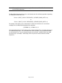
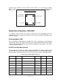
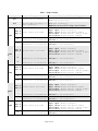
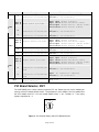
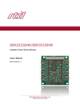
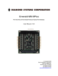
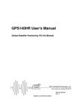
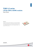
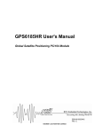
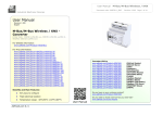
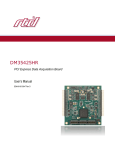
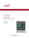
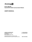
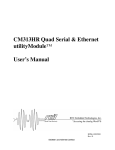
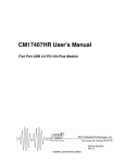
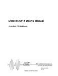
CM17320HR User's Manual
Octal RS-232/422/485 PC/104-Plus Module
BDM-610020049
Rev E
ISO9001 and AS9100 Certified
CM17320HR User's Manual
RTD EMBEDDED TECHNOLOGIES, INC.
103 Innovation Blvd
State College, PA 16803-0906
Phone: +1-814-234-8087
FAX: +1-814-234-5218
E-mail
[email protected]
[email protected]
Web Site
http://www.rtd.com
Page 2 of 26
Manual Revision History
Rev A
New manual
Rev B
Added User Oscillator
Rev C (01/31/2008)
Added a section about supported baud rates.
Added a diagram of the User Oscillator.
Added information about COM port numbering in Windows.
Added section on COM port enumeration for application developers.
Rev D (08/13/2008)
- Added the IDAN-CM17320 Dimensions and Pinout section, which
replaces the (previously separate) IDAN Manual, IDM-650020032.
- Corrected the IDAN connector pinout, which was listed incorrectly
in IDM-650020032 rev A.
- Added information about RTD pre-installed User Oscillators
- Expanded the board block diagram to clarify the oscillator operation
- Renamed the jumper designations for the signal conditioning jumpers.
They now use the designations printed on the board silk, rather than the
JPxx designation from the schematic.
- Improved the Connector and Jumper Locations diagram.
- Changed the name of the RS-422/485 Transmitter control section to
more accurately indicate its purpose.
Rev E (8/17/2009)
- Added spec for External clock input
- Added second mode jumper to get RS-422 with drivers always enabled
and RS-485 with inverted RTS driver enable modes in addition to RS232 and RS-422/485 (now just RS-485 mode) with RTS driver enable
modes
Published by:
RTD Embedded Technologies, Inc.
103 Innovation Boulevard
State College, PA 16803
Copyright 2006 by RTD Embedded Technologies, Inc.
All rights reserved
The RTD Embedded Technologies Logo is a registered trademark of RTD Embedded
Technologies. dspModule, cpuModule, and utilityModule are trademarks of RTD Embedded
Technologies. PC/104, PC/104-Plus, and PCI-104 are registered trademarks of the PC/104
Page 3 of 26
Consortium. All other trademarks appearing in this document are the property of their respective
owners.
Page 4 of 26
Table of Contents
Introduction ...................................................................................................................................... 7
Product Overview......................................................................................................................... 7
Board Features ............................................................................................................................ 7
I/O Interfaces................................................................................................................................ 7
Available Options ......................................................................................................................... 7
Getting Technical Support ........................................................................................................... 8
Hardware Description ...................................................................................................................... 9
Block Diagram.............................................................................................................................. 9
Supported Baud Rates................................................................................................................. 9
Board Connections ........................................................................................................................ 11
Connector and Jumper Locations .............................................................................................. 11
User Oscillator, U3 ..................................................................................................................... 11
Serial Port Connectors, CN4-CN11 ........................................................................................... 12
First serial port, CN4 .............................................................................................................. 12
RS-232 Serial Port Mode (Default) ..................................................................................... 12
RS-422/485 Serial Port Mode............................................................................................. 13
Second serial port, CN5 ......................................................................................................... 14
Third serial port, CN6 ............................................................................................................. 14
Fourth serial port, CN7 ........................................................................................................... 14
Fifth serial port, CN8 .............................................................................................................. 14
Sixth serial port, CN9 ............................................................................................................. 14
Seventh serial port, CN10 ...................................................................................................... 14
Eighth serial port, CN11 ......................................................................................................... 14
Jumper Settings ......................................................................................................................... 14
PCI Board Selector, SW1 .......................................................................................................... 16
Board Installation ........................................................................................................................... 17
Installing the Hardware .............................................................................................................. 17
Static Precautions .................................................................................................................. 17
Steps for Installing.................................................................................................................. 17
Page 5 of 26
Installing the Software................................................................................................................ 17
Software Programming.................................................................................................................. 19
API Interface .............................................................................................................................. 19
COM Port Numbering ................................................................................................................ 19
Base Address and Register Mapping ........................................................................................ 19
Enabling the RS-422/485 Transmitter........................................................................................ 19
Interrupts .................................................................................................................................... 20
Additional Information .................................................................................................................... 21
Serial Port Programming............................................................................................................ 21
Interrupt Programming ............................................................................................................... 21
Exar XR17D158 PCI Bus Octal UART ...................................................................................... 21
CM17320HR Board Specifications ................................................................................................ 22
Physical Attributes ..................................................................................................................... 22
Operating Conditions.............................................................................................................. 22
IDAN-CM17320HRS Dimensions and Pinout ............................................................................... 23
IDAN Frame ............................................................................................................................... 23
IDAN Connectors ....................................................................................................................... 24
37-pin “D” Female Connectors ............................................................................................... 24
Serial Ports 1-4 (Front)........................................................................................................... 24
Serial Ports 5-8 (Back) ........................................................................................................... 25
Limited Warranty............................................................................................................................ 26
Page 6 of 26
Introduction
Product Overview
The CM17320HR is designed to provide eight independent PCI serial ports with RS-232, RS-422,
or RS-485 interfaces for PC/104-Plus based systems.
Board Features
o
o
o
o
Eight versatile serial port interfaces
Jumper-selectable RS-232, RS-422 drivers always enabled, RS-485 with
RTS driver enable and RS-485 with inverted RTS driver enable operation
Supports all standard RS-232 serial port signals (RTS, CTS, etc).
Functionally compatible with standard PC 16C550 UARTs
Exar XR17D158 Octal PCI UART
32-bit PCI target
16C550 compatible 5G register set
64 byte transmit and receive FIFOs
Programmable date rate with prescaler
14.7456 MHz crystal
Standard PC serial port baud rates supported
Up to 921,600 baud RS-422/485 (prescaler = 1)
Up to 230,400 baud RS-232 (prescaler = 4)
User oscillator option
Enables support for non-standard baud rates up to 6.25 Mbps
+3.3 V or 5 V Oscillators, 50 MHz max
8-pin DIP package (4 pins used)
Board may be ordered with a custom oscillator preinstalled.
PC/104-Plus compliant
Universal (3.3V or 5.0V) PCI signaling
I/O Interfaces
o
o
o
Eight 10-pin DIL serial port connectors
0.1” Pin Spacing
Can be cabled directly to a 9-pin “D” connector
PC/104-Plus (PCI) stack-through bus connector
PC/104 (ISA) stack-through bus connector
Available Options
The CM17320HR may be purchased as either a board-level product, or as an IDAN module for
integration into an RTD IDAN system. Cable kits are also available.
Part Number
Description
CM17320HR
Octal Serial Port Peripheral Module
CM17320HR-xxx.xxxMHz
CM17320HR with pre-installed oscillator for custom
baud rates (xxx.xxx specifies the frequency)
Page 7 of 26
XK-CM30
Quad Serial Port Cable Kit
(To connect all 8 ports, purchase two XK-CM30s)
IDAN-CM17320HRS
CM17320HR mounted in an IDAN frame
May also specify a custom oscillator frequency.
IDAN-CM17320HRS/xxx.xxxMHz
IDAN-XKCM33
IDAN-CM17320HRS with pre-installed oscillator
for custom baud rates (xxx.xxx specifies the
frequency)
IDAN Multi Serial Port Cable (4 ports)
(To connect all 8 ports, purchase two IDAN-XKCM33s)
In addition to the above ordering options, RTD can also provide the CM17320HR with various
customizations (e.g. conformal coating, custom connectors, soldered jumpers, etc). Contact
RTD’s sales department ([email protected]) for more information.
Getting Technical Support
If you are having problems with your system, please try the following troubleshooting steps:
•
Simplify the System – Remove modules one at a time from your system to see if there
is a specific module that is causing a problem.
•
Swap Components – Try replacing parts in the system one-at-a-time with similar parts
to determine if a part is faulty or if a type of part is configured incorrectly.
If problems persist, or you have questions about configuring this product, obtain the PCI BIOS
listing information of the CM17320HR and other modules in the system. After you have this
information, contact RTD Embedded Technologies via the following methods:
Phone: +1-814-234-8087
E-Mail: [email protected]
Be sure to check the RTD web site (http://www.rtd.com) frequently for product updates, including
newer versions of the board manual and application software.
Page 8 of 26
Hardware Description
PC/104-Plus Connector (CN3)
Block Diagram
PCI
Bus
Exar
XR17D158
PCI UART
Signal Conditioning
(Jumper-Controlled)
COM a
RS-232/422/485
CN4
COM b
RS-232/422/485
CN5
COM c
RS-232/422/485
CN6
COM d
RS-232/422/485
CN7
COM e
RS-232/422/485
CN8
COM f
RS-232/422/485
CN9
COM g
RS-232/422/485
CN10
COM h
RS-232/422/485
CN11
14.7456 MHz
Oscillator
UART Input
Clock
Oscillator Select
Jumper (JP2)
User Oscillator
(U3)
+5V
U3 VCC
+3.3V
User Oscillator Power
Jumper (JP27)
Figure 1 CM17320 Block Diagram
Supported Baud Rates
When using the standard 14.7456 MHz oscillator, the CM17320HR supports the standard baud
rates of PC serial port (e.g. 2400, 9600, 19.2k, etc). The CM17320HR can also support nonstandard baud rates via a User Oscillator.
The baud rate of a serial port is set by dividing the input clock (typically 14.7546MHz). For the
Exar XR17D158, there are two dividers to specify. First is the Prescaler (MCR Bit 7), divides the
input clock by either 1 or 4. Second is the Baud Rate Generator, which further divides the
frequency further to achieve the desired baud rate. The Baud Rate Generator can be set to a
16
value between 1 and (2 -1).
Page 9 of 26
Note:
For more information on programming the Prescaler and Baud Rate Generator, consult
the XR17D158 datasheet.
The Baud Rate Generator divisor can be calculated by one of the following equations depending
on sampling of receiver of 8 or 16:
Divisor = (INPUT_CLOCK / PRESCALER) / (DESIRED_BAUD_RATE x 16)
or
Divisor = (INPUT_CLOCK / PRESCALER) / (DESIRED_BAUD_RATE x 8)
For example, if one wants to use a baud rate of 115.2K, Prescale divisor of 4, and receiver
sampling of 16, the Baud Rate Generator divisor would be:
(14745600 / 4) / (115200 x 16) = 2
If the desired baud rate can not be expressed as a whole number divisor, it may be necessary to
use a different input clock. This can be done with a User Oscillator. A user-specified oscillator
can be installed in U3. The max frequency for the user oscillator is 50 MHz and the max baud
rate for the chip is 6.25 Mbps. Alternatively, RTD can preinstall several common oscillator
frequencies.
Page 10 of 26
Board Connections
Connector and Jumper Locations
The following diagram shows the location of all connectors and jumpers on the CM17320HR.
Future revisions of the CM17320HR may have cosmetic differences. For a description of each
jumper and connector, refer to the following sections.
PC/104-Plus
PCI Bus
CN8
th
5 serial port
CN7
th
4 serial port
CN9
th
6 serial port
CN6
rd
3 serial port
CN10
th
7 serial port
CN5
nd
2 serial port
CN11
th
8 serial port
CN4
st
1 serial port
JP2 – Oscillator Select
JP27 – User Oscillator Power
SW1 PCI
Slot Selector
PC/104-Plus
ISA Bus
Serial Port
Signal Conditioning
(4 jumpers per port)
Mode A & B = Signaling Mode
R = RxD Termination
C = CTS Termination
U3 – User Oscillator
Figure 2 – CM17320 Connector and jumper locations
User Oscillator, U3
The board has a position for a half size, 8-pin DIP, user oscillator. This device can be either a 5
volt or 3.3 volt oscillator and is configured with jumper JP27. Jumper JP2 selects either the
14.7456 MHz oscillator or the user oscillator. All serial ports use the same oscillator. U3 pin 1 is
Page 11 of 26
pulled high with a 10K ohm resistor to enable tri-state oscillators. The max frequency is 50MHz
which
will
result in a max
baud rate of
6.25Mbps.
User Oscillator U3 Pinout
Pin 4 VCC
(Set by JP27)
Pin 3 CLOCK
Pin 2 GND
Pin 1 OE
Serial Port Connectors, CN4-CN11
The following sections describe the external I/O connections of the CM17320HR board. For
information on the I/O connections for the IDAN version, refer to the IDAN-CM17320HRS section
later in this manual.
First serial port, CN4
The first serial port is implemented on connector CN4. It can be configured as a PC compatible
full duplex RS-232 port, full duplex RS-422 with drivers always enabled, RS-485 with RTS driver
enable, or RS-485 with inverted RTS driver enable by the “Mode A and B” jumpers. See Table 5
– Jumper Settings for details.
RS-232 Serial Port Mode (Default)
The full-duplex RS-232 mode is the default setting on the utilityModule. With this mode enabled,
connector CN4 must be connected to RS-232 compatible devices. The following table gives the
connector pinout and shows how to connect to an external serial connector, either DB25 or DB9.
Table 1 Connector CN4 in RS-232 Mode (I)
CN4 Pin
Signal
Function
In/out
DB25
DB9
1
DCD
Data Carrier Detect
In
8
1
2
DSR
Data Set Ready
In
6
6
3
RXD
Receive Data
In
3
2
4
RTS
Request To Send
Out
4
7
5
TXD
Transmit Data
Out
2
3
6
CTS
Clear To Send
In
5
8
7
DTR
Data Terminal Ready
Out
20
4
Page 12 of 26
8
RI
Ring Indicate
In
22
9
9,10
GND
Signal Ground
--
7
5
Facing the connector pins, the pinout is pictured in the following,
Table 2 Connector CN4 in RS-232 Mode (II)
9
7
5
3
1
GND
DTR
TXD
RXD
DCD
GND
RI
CTS
RTS
DSR
10
8
6
4
2
RS-422, RS-485 RTS, RS-485 Inverted RTS Serial Port Modes
When using RS-422 or RS-485 mode, you can use the port in either half-duplex (two-wire) or fullduplex (four-wire) configurations. For half-duplex (2-wire) operation, you must connect RXD+ to
TDX+ and connect RXD- to TXD-.
Note:
120-ohm termination resistors for the RxD and CTS signals are provided on the
utilityModule. Termination is usually necessary on all RS-422 receivers and at the ends
of the RS-485 bus. If the termination resistor is required, it can be enabled by closing
jumpers labeled “R” and “C” for the corresponding port. For more information, refer to the
Jumper Settings table later in this chapter.
The following table gives the pinout of connector CN4 when RS-422 or RS-485 modes are
enabled.
Table 3 Connector CN4 in RS-422/485 Mode (I)
CN3 Pin
Signal
Function
In/out
DB9
1
RTS-
Request to send (-)
Out
1
2
RTS+
Request to send (+)
Out
6
3
RXD-
Receive Data (-)
In
2
4
TXD+
Transmit Data (+)
Out
7
5
TXD-
Transmit Data(-)
Out
3
6
RXD+
Receive Data (+)
In
8
7
CTS-
Clear to send (-)
In
4
8
CTS+
Clear to send (+)
In
9
9,10
GND
Signal Ground
--
5
Page 13 of 26
Facing the connector pins, the pinout is pictured in the following table.
Table 4 Connector CN4 in RS-422/485 Mode (II)
9
7
5
3
1
GND
CTS-
TXD-
RXD-
RTS-
GND
CTS+
RXD+
TXD+
RTS+
10
8
6
4
2
Second serial port, CN5
Please refer to the previous section on the first COM port, CN4 for the description.
Third serial port, CN6
Please refer to the previous section on the first COM port, CN4 for the description.
Fourth serial port, CN7
Please refer to the previous section on the first COM port, CN4 for the description.
Fifth serial port, CN8
Please refer to the previous section on the first COM port, CN4 for the description.
Sixth serial port, CN9
Please refer to the previous section on the first COM port, CN4 for the description.
Seventh serial port, CN10
Please refer to the previous section on the first COM port, CN4 for the description.
Eighth serial port, CN11
Please refer to the previous section on the first COM port, CN4 for the description.
Jumper Settings
The following sections describe the jumper configuration options available on the CM17320HR.
For a reference that shows the location of each set of jumpers, refer to the diagram of the
CM17320HR at the beginning of this chapter. The default factory jumper settings are listed in the
following table:
Page 14 of 26
Table 5 – Jumper Settings
Jumper
Description
JP1
Bypass PCI bus EEPROM
JP2
14.7456 MHz Oscillator or
User Oscillator
Mode A
Mode B
First serial port mode
CN4
R
C
Mode A
Mode B
First serial port RxD
termination in RS-422/485
First serial port CTS
termination in RS-422/485
Second serial port mode
CN5
R
C
Mode A
Mode B
Second serial port RxD
termination in RS-422/485
Second serial port CTS
termination in RS-422/485
Third serial port mode
CN6
R
C
Mode A
Mode B
Third serial port RxD
termination in RS-422/485
Third serial port CTS
termination in RS-422/485
Fourth serial port mode
CN7
R
C
CN8
Mode A
Mode B
R
Fourth serial port RxD
termination in RS-422/485
Fourth serial port CTS
termination in RS-422/485
Fifth serial port mode
Fifth serial port RxD
termination in RS-422/485
Function and Default Setting
1-2 for Normal operation (default)
2-3 Factory use only
1-2 14.7456 MHz (default)
2-3 User Oscillator
Note: Be sure to set JP27 if using a User Oscillator.
B
A
Mode
Open Open RS-232 (Default)
Open Close RS-485 RTS driver enable
Close Open RS-485 RTS inv. driver enable
Close Close RS-422 drivers enabled
Open
No termination (default)
Closed 120 Ohm Termination
Open
No termination (default)
Closed 120 Ohm Termination
B
A
Mode
Open Open RS-232 (Default)
Open Close RS-485 RTS driver enable
Close Open RS-485 RTS inv. driver enable
Close Close RS-422 drivers enabled
Open
No termination (default)
Closed 120 Ohm Termination
Open
No termination (default)
Closed 120 Ohm Termination
B
A
Mode
Open Open RS-232 (Default)
Open Close RS-485 RTS driver enable
Close Open RS-485 RTS inv. driver enable
Close Close RS-422 drivers enabled
Open
No termination (default)
Closed 120 Ohm Termination
Open
No termination (default)
Closed 120 Ohm Termination
B
A
Mode
Open Open RS-232 (Default)
Open Close RS-485 RTS driver enable
Close Open RS-485 RTS inv. driver enable
Close Close RS-422 drivers enabled
Open
No termination (default)
Closed 120 Ohm Termination
Open
No termination (default)
Closed 120 Ohm Termination
B
A
Mode
Open Open RS-232 (Default)
Open Close RS-485 RTS driver enable
Close Open RS-485 RTS inv. driver enable
Close Close RS-422 drivers enabled
Open
No termination (default)
Closed 120 Ohm Termination
Page 15 of 26
Jumper
C
Mode A
Mode B
Description
Fifth serial port CTS
termination in RS-422/485
Sixth serial port mode
CN9
R
C
Mode A
Mode B
Sixth serial port RxD
termination in RS-422/485
Sixth serial port CTS
termination in RS-422/485
Seventh serial port mode
CN10
R
C
Mode A
Mode B
CN11
R
C
JP27
Seventh serial
termination in
Seventh serial
termination in
port RxD
RS-422/485
port CTS
RS-422/485
Eighth serial port mode
Eighth serial port RxD
termination in RS-422/485
mode
Eighth serial port CTS
termination in RS-422/485
mode
User Oscillator power
source selection
Function and Default Setting
Open
No termination (default)
Closed 120 Ohm Termination
B
A
Mode
Open Open RS-232 (Default)
Open Close RS-485 RTS driver enable
Close Open RS-485 RTS inv. driver enable
Close Close RS-422 drivers enabled
Open
No termination (default)
Closed 120 Ohm Termination
Open
No termination (default)
Closed 120 Ohm Termination
B
A
Mode
Open Open RS-232 (Default)
Open Close RS-485 RTS driver enable
Close Open RS-485 RTS inv. driver enable
Close Close RS-422 drivers enabled
Open
No termination (default)
Closed 120 Ohm Termination
Open
No termination (default)
Closed 120 Ohm Termination
B
A
Mode
Open Open RS-232 (Default)
Open Close RS-485 RTS driver enable
Close Open RS-485 RTS inv. driver enable
Close Close RS-422 drivers enabled
Open
No termination (default)
Closed 120 Ohm Termination
Open
No termination (default)
Closed 120 Ohm Termination
1-2 +5V (default)
2-3 +3.3V
PCI Board Selector, SW1
The CM17320HR uses a rotary switch to select the PCI slot. Before you can use this module you
have to set the PCI board selector switch. The procedure is if this module is the first module from
the CPU module select ’0,’ if it is the second module select ’1,’ etc. Positions 4 - 7 are simply
repeats of positions 0 – 3.
7 0 1
6
5
2
4
3
Figure 3: PCI Selector Rotary Switch PCI Board Selector
Page 16 of 26
Board Installation
Installing the Hardware
The CM17320HR can be installed into a PC/104-Plus or PCI-104 stack. It can be located almost
anywhere in the stack, above or below the CPU as long as all PCI bus constraints are met.
Static Precautions
Keep your board in its antistatic bag until you are ready to install it into your system! When
removing it from the bag, hold the board at the edges, and do not touch the components or
connectors. Handle the board in an antistatic environment, and use a grounded workbench for
testing and handling of your hardware.
Steps for Installing
1. Shut down the PC/104-Plus system and unplug the power cord.
2. Ground yourself with an anti-static strap.
3. Set the PCI Slot Selector as described in the previous chapter.
4. If any other PCI add-on cards are to be included in the stack, be sure that their PCI slot
numbers are configured correctly (Slot 0 for the board closest to the CPU, Slot 1 for the
next board, etc).
5. Line up the pins of the CM17320’s PC/104 and PC/104-Plus connectors with the
corresponding bus connectors of the stack. Make sure that both connectors are lined up.
6. Apply pressure to both bus connectors and gently press the board onto the stack. The
board should slide into the matching bus connectors. Do not attempt to force the board,
as this can lead to bent/broken pins.
7. If any boards are to be stacked above the CM17320, install them.
8. Attach any necessary cables to the PC/104-Plus stack.
9. Re-connect the power cord and apply power to the stack.
10. Boot the system and verify that all of the hardware is working properly.
Note:
If multiple PCI devices are configured to use the same PCI slot number, the system may
not boot.
Installing the Software
The CM17320HR uses a PCI-based UART, not the standard ISA-based UART found in most PC
motherboards. Therefore, it may be necessary to install software before the board will be
recognized by the operating system. RTD provides drivers for several popular operating
systems. This software is provided on disk with the board, and is also available for download
from the RTD web site (http://www.rtd.com).
Page 17 of 26
Note:
Before installing any drivers, it is recommended that you visit the RTD web site to check
for a newer version.
The actual procedure for installing the software will depend on the operating system. Consult the
documentation provided with the software for installation instructions.
Once the drivers are installed, all eight ports should be available as standard serial ports (a.k.a.
COM ports) to the operating system. At that point, application software should be able to access
and control the serial ports.
Note:
When the CM17320HR is installed under Windows, it typically uses a contiguous set of
COM port numbers (e.g. COM3-COM10). If the CM17320HR is installed in a system with
more than two COM ports, there may be overlap between the COM port numbers. It may
be necessary to re-number the existing COM ports to avoid conflicts with the
CM17320HR. Consult the Windows driver documentation for more information.
Page 18 of 26
Software Programming
API Interface
Once the drivers for the CM17320HR have been properly loaded, all eight RS-232/422/485 ports
should be available as standard serial ports. All eight ports can then be controlled using the
standard serial port interfaces built into the operating system.
A description of serial port programming for operating systems is beyond the scope of this
manual. Consult the operating system documentation for information on how to interface with
serial ports via software.
COM Port Numbering
Serial ports (aka COM ports) are typically assigned numbers by the operating system (e.g.
COM1). These numbers are typically dynamically assigned by the operating system. However,
different applications may enumerate the COM ports differently, assigning different port numbers
(e.g. COM3-10 vs COM5-12). When developing your own serial port application, consult your
operating system’s documentation for the proper method of enumerating COM ports.
Note:
Some applications are written to assume that no more than four COM ports are present
in a system. These applications may have compatibility issues with the Exar PCI UART.
Base Address and Register Mapping
The CM17320HR exposes all of the registers available on the Exar XR17D158. The register set
of the XR17D158 mimics the standard 16C550 UART register map. However, the XR17D158
contains some additional registers not found in a typical ISA-based UART.
Additionally, the base address of the CM17320HR’s serial ports will be different than the standard
PC serial port locations (0x3F8, 0x2F8, etc). The CM17320HR is a memory mapped device.
Since it is PCI-based, it may be mapped to any location within the 4GB address space of the
CPU. The base address of PCI devices is determined by the CPU’s BIOS and operating system
at boot time.
The register-level differences between the CM17320HR and a standard 16C550 UART should be
abstracted via the software drivers. Most users will not need to concern themselves with the
actual registers of the board. If one is interested in directly accessing the registers of the board,
consult the XR17D158 data sheet available from Exar.
Enabling the RS-422/485 Transmitter
See Table 5 – Jumper Settings for mode jumper settings. When using the serial port in RS-422
or RS-485 mode, the serial receiver for RxD (receive data) is always enabled.
In RS-422 mode the driver is always enabled, however in RS-485 mode the driver for TxD
(transmit data) is enabled and disabled under software control in the following two ways.
In RS-485 RTS driver enable mode the transmitter is enabled by manipulating the Request to
Send (RTS) signal of the serial port controller. This signal is controlled by writing bit 1 of the
Modem Control Register (MCR) as follows:
Page 19 of 26
•
If MCR bit 1 = 1, then RTS = 0, and serial transmitter is disabled
•
If MCR bit 1 = 0, then RTS = 1, and serial transmitter is enabled
If you are using the RS-485 inverted RTS driver enable mode these settings will be reversed as
follows:
•
If MCR bit 1 = 1, then RTS = 0, and serial transmitter is enabled
•
If MCR bit 1 = 0, then RTS = 1, and serial transmitter is disabled
If you are using the handshaking signals in RS-422/485 mode, the serial receiver for CTS (clear
to send) is always enabled, and the serial transmitter for RTS (request to send) is always
enabled.
The exact software method for toggling RTS will depend on your operating system. Consult your
operating system’s programming documentation for information on how to do this.
"NOTE: Many serial communication programs (e.g. Windows HyperTerminal) do not assert
RTS while transmitting. When using these programs, make sure jumper that
enables the transmitters all the time is installed. If using a multi-drop bus such as
RS485, the software will have to be modified to toggle RTS to enable the transmit
drivers.”
Interrupts
Since the CM17320HR is a PCI device, it is capable of sharing interrupts with other PCI devices.
Interrupt sharing is a normal part of PCI operation, and a required part of the PCI specification.
Note that any Interrupt Service Routines developed for the CM17320HR must be properly written
to support interrupt sharing.
The CM17320HR uses one PCI interrupt for all eight serial ports. The actual IRQ number will be
set by the CPU’s BIOS and operating system at boot time.
Since the XR17D158 has all the capabilities of a standard 16C550 UART, it supports all of the
standard serial port interrupt events. However, it will not actually generate interrupts unless the
Interrupt Enable Register has been properly programmed for each port. Supported interrupt
events include:
•
Received data available
•
Transmit buffer empty
•
Line Status Register change
•
Modem Status Register change
A detailed explanation of serial port interrupts is beyond the scope of this manual. For more
information, consult a serial port programming reference.
Note:
When the UART clock is running at a higher frequency, transmit/receive interrupts will
happen more frequently. Many operating systems can not process interrupts quickly
enough to handle this load. When developing your software, be sure to consider the
operating system’s limitations.
Page 20 of 26
Additional Information
Serial Port Programming
For more information about programming serial port UARTs, consult the following book:
Serial Communications Developer’s Guide
By Mark Nielson
ISBN: 0764545701
Interrupt Programming
For more information about interrupts and writing interrupt service routines, refer to the following
book:
Interrupt-Driven PC System Design
By Joseph McGivern
ISBN: 0929392507
Exar XR17D158 PCI Bus Octal UART
For detailed information about the Exar XR17D158, contact Exar at:
Web:
http://www.exar.com
Page 21 of 26
CM17320HR Board Specifications
Physical Attributes
Size:
3.6”L x 3.8”W x 0.6”H (90mm L x 96mm W x 15mm H)
Weight:
0.24bs (0.10 Kg)
Power Consumption:
2W @ 5 VDC Typical
Operating Conditions
Cooling
Convection
Operating temperature range
-40º to +85ºC
Storage temperature range
-55 C to +125 C
Humidity
RH up to 95% non-condensing
o
Page 22 of 26
o
IDAN-CM17320HRS Dimensions and Pinout
IDAN Frame
FRONT
BACK
Pin 1
Pin 19
Pin 20
Pin 37
Pin 19
Pin 1
Pin 37
Note:
Pin 20
Drawings are not to scale.
Page 23 of 26
IDAN Connectors
37-pin “D” Female Connectors
Connector Part #: Adam Tech DE37SD
Mating Connector: Adam Tech DE37PD
Serial Port 1
Serial Port 2
Serial Port 3
Serial Port 4
Serial Ports 1-4 (Front)
IDAN
Pin #
1
2
3
4
5
20
21
22
23
24
25
26
27
28
6
7
8
9
10
11
12
13
14
29
30
31
32
33
34
35
36
37
15
16
17
18
19
RS-232 Signal
Carrier Detect
Receive Data
Transmit Data
Data Terminal Ready
GND
Data Set Ready
Request To Send
Clear To Send
Ring Indicator
Carrier Detect
Receive Data
Transmit Data
Data Terminal Ready
GND
Data Set Ready
Request To Send
Clear To Send
Ring Indicator
Carrier Detect
Receive Data
Transmit Data
Data Terminal Ready
GND
Data Set Ready
Request To Send
Clear To Send
Ring Indicator
Carrier Detect
Receive Data
Transmit Data
Data Terminal Ready
GND
Data Set Ready
Request To Send
Clear To Send
Ring Indicator
N/C
RS-422/485 Signal
Request To Send (-)
Receive Data (-)
Transmit Data (-)
Clear To Send (-)
GND
Request To Send (+)
Transmit Data (+)
Receive Data (+)
Clear To Send (+)
Request To Send (-)
Receive Data (-)
Transmit Data (-)
Clear To Send (-)
GND
Request To Send (+)
Transmit Data (+)
Receive Data (+)
Clear To Send (+)
Request To Send (-)
Receive Data (-)
Transmit Data (-)
Clear To Send (-)
GND
Request To Send (+)
Transmit Data (+)
Receive Data (+)
Clear To Send (+)
Request To Send (-)
Receive Data (-)
Transmit Data (-)
Clear To Send (-)
GND
Request To Send (+)
Transmit Data (+)
Receive Data (+)
Clear To Send (+)
N/C
Page 24 of 26
CM17320
Pin #
CN7-1
CN7-3
CN7-5
CN7-7
CN7-9
CN7-2
CN7-4
CN7-6
CN7-8
CN6-1
CN6-3
CN6-5
CN6-7
CN6-9
CN6-2
CN6-4
CN6-6
CN6-8
CN5-1
CN5-3
CN5-5
CN5-7
CN5-9
CN5-2
CN5-4
CN5-6
CN5-8
CN4-1
CN4-3
CN4-5
CN4-7
CN4-9
CN4-2
CN4-4
CN4-6
CN4-8
N/C
IDAN-XKCM33 Cable Kit
9 Pin "D" Connector (Male)
PORT 4-1
PORT 4-2
PORT 4-3
PORT 4-4
PORT 4-5
PORT 4-6
PORT 4-7
PORT 4-8
PORT 4-9
PORT 3-1
PORT 3-2
PORT 3-3
PORT 3-4
PORT 3-5
PORT 3-6
PORT 3-7
PORT 3-8
PORT 3-9
PORT 2-1
PORT 2-2
PORT 2-3
PORT 2-4
PORT 2-5
PORT 2-6
PORT 2-7
PORT 2-8
PORT 2-9
PORT 1-1
PORT 1-2
PORT 1-3
PORT 1-4
PORT 1-5
PORT 1-6
PORT 1-7
PORT 1-8
PORT 1-9
N/C
Serial Port 5
Serial Port 6
Serial Port 7
Serial Port 8
Serial Ports 5-8 (Back)
IDAN
Pin #
1
2
3
4
5
20
21
22
23
24
25
26
27
28
6
7
8
9
10
11
12
13
14
29
30
31
32
33
34
35
36
37
15
16
17
18
19
RS-232 Signal
Carrier Detect
Receive Data
Transmit Data
Data Terminal Ready
GND
Data Set Ready
Request To Send
Clear To Send
Ring Indicator
Carrier Detect
Receive Data
Transmit Data
Data Terminal Ready
GND
Data Set Ready
Request To Send
Clear To Send
Ring Indicator
Carrier Detect
Receive Data
Transmit Data
Data Terminal Ready
GND
Data Set Ready
Request To Send
Clear To Send
Ring Indicator
Carrier Detect
Receive Data
Transmit Data
Data Terminal Ready
GND
Data Set Ready
Request To Send
Clear To Send
Ring Indicator
N/C
RS-422/485 Signal
Request To Send (-)
Receive Data (-)
Transmit Data (-)
Clear To Send (-)
GND
Request To Send (+)
Transmit Data (+)
Receive Data (+)
Clear To Send (+)
Request To Send (-)
Receive Data (-)
Transmit Data (-)
Clear To Send (-)
GND
Request To Send (+)
Transmit Data (+)
Receive Data (+)
Clear To Send (+)
Request To Send (-)
Receive Data (-)
Transmit Data (-)
Clear To Send (-)
GND
Request To Send (+)
Transmit Data (+)
Receive Data (+)
Clear To Send (+)
Request To Send (-)
Receive Data (-)
Transmit Data (-)
Clear To Send (-)
GND
Request To Send (+)
Transmit Data (+)
Receive Data (+)
Clear To Send (+)
N/C
Page 25 of 26
CM17320
Pin #
CN11-1
CN11-3
CN11-5
CN11-7
CN11-9
CN11-2
CN11-4
CN11-6
CN11-8
CN10-1
CN10-3
CN10-5
CN10-7
CN10-9
CN10-2
CN10-4
CN10-6
CN10-8
CN9-1
CN9-3
CN9-5
CN9-7
CN9-9
CN9-2
CN9-4
CN9-6
CN9-8
CN8-1
CN8-3
CN8-5
CN8-7
CN8-9
CN8-2
CN8-4
CN8-6
CN8-8
N/C
IDAN-XKCM33 Cable Kit
9 Pin "D" Connector (Male)
PORT 8-1
PORT 8-2
PORT 8-3
PORT 8-4
PORT 8-5
PORT 8-6
PORT 8-7
PORT 8-8
PORT 8-9
PORT 7-1
PORT 7-2
PORT 7-3
PORT 7-4
PORT 7-5
PORT 7-6
PORT 7-7
PORT 7-8
PORT 7-9
PORT 6-1
PORT 6-2
PORT 6-3
PORT 6-4
PORT 6-5
PORT 6-6
PORT 6-7
PORT 6-8
PORT 6-9
PORT 5-1
PORT 5-2
PORT 5-3
PORT 5-4
PORT 5-5
PORT 5-6
PORT 5-7
PORT 5-8
PORT 5-9
N/C
Limited Warranty
RTD Embedded Technologies, Inc. warrants the hardware and software products it manufactures
and produces to be free from defects in materials and workmanship for one year following the
date of shipment from RTD EMBEDDED TECHNOLOGIES, INC. This warranty is limited to the
original purchaser of product and is not transferable.
During the one year warranty period, RTD EMBEDDED TECHNOLOGIES will repair or replace,
at its option, any defective products or parts at no additional charge, provided that the product is
returned, shipping prepaid, to RTD EMBEDDED TECHNOLOGIES. All replaced parts and
products become the property of RTD EMBEDDED TECHNOLOGIES. Before returning any
product for repair, customers are required to contact the factory for an RMA number.
THIS LIMITED WARRANTY DOES NOT EXTEND TO ANY PRODUCTS WHICH HAVE BEEN
DAMAGED AS A RESULT OF ACCIDENT, MISUSE, ABUSE (such as: use of incorrect input
voltages, improper or insufficient ventilation, failure to follow the operating instructions that are
provided by RTD EMBEDDED TECHNOLOGIES, "acts of God" or other contingencies beyond
the control of RTD EMBEDDED TECHNOLOGIES), OR AS A RESULT OF SERVICE OR
MODIFICATION BY ANYONE OTHER THAN RTD EMBEDDED TECHNOLOGIES. EXCEPT AS
EXPRESSLY SET FORTH ABOVE, NO OTHER WARRANTIES ARE EXPRESSED OR
IMPLIED, INCLUDING, BUT NOT LIMITED TO, ANY IMPLIED WARRANTIES OF
MERCHANTABILITY AND FITNESS FOR A PARTICULAR PURPOSE, AND RTD EMBEDDED
TECHNOLOGIES EXPRESSLY DISCLAIMS ALL WARRANTIES NOT STATED HEREIN. ALL
IMPLIED WARRANTIES, INCLUDING IMPLIED WARRANTIES FOR MECHANTABILITY AND
FITNESS FOR A PARTICULAR PURPOSE, ARE LIMITED TO THE DURATION OF THIS
WARRANTY. IN THE EVENT THE PRODUCT IS NOT FREE FROM DEFECTS AS
WARRANTED ABOVE, THE PURCHASER'
S SOLE REMEDY SHALL BE REPAIR OR
REPLACEMENT AS PROVIDED ABOVE. UNDER NO CIRCUMSTANCES WILL RTD
EMBEDDED TECHNOLOGIES BE LIABLE TO THE PURCHASER OR ANY USER FOR ANY
DAMAGES, INCLUDING ANY INCIDENTAL OR CONSEQUENTIAL DAMAGES, EXPENSES,
LOST PROFITS, LOST SAVINGS, OR OTHER DAMAGES ARISING OUT OF THE USE OR
INABILITY TO USE THE PRODUCT.
SOME STATES DO NOT ALLOW THE EXCLUSION OR LIMITATION OF INCIDENTAL OR
CONSEQUENTIAL DAMAGES FOR CONSUMER PRODUCTS AND SOME STATES DO NOT
ALLOW LIMITATIONS ON HOW LONG AN IMPLIED WARRANTY LASTS, SO THE ABOVE
LIMITATIONS OR EXCLUSIONS MAY NOT APPLY TO YOU.
THIS WARRANTY GIVES YOU SPECIFIC LEGAL RIGHTS, AND YOU MAY ALSO HAVE
OTHER RIGHTS WHICH VARY FROM STATE TO STATE.
Page 26 of 26