1
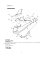
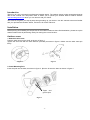
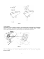
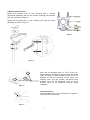
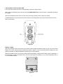
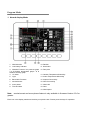
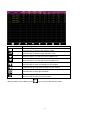
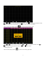
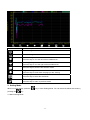
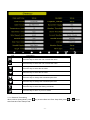
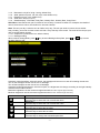
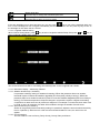
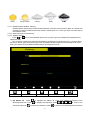
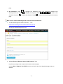
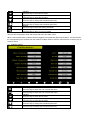
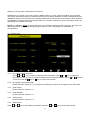
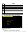
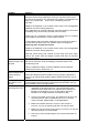
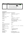
PROFESSIONAL WIRELESS INTERNET WEATHER
STATION
Operation Manual
-1-
OVERVIEW
Outdoor sensor:
1. Wind Vane
2. Wind Speed Sensor
3. Solar panel
4. Battery compartment
5. LED Indicator: light on for 4s if the unit power up. Then the LED will flash once every 16 seconds (the
sensor transmission update period).
6. Reset button
7. Thermo-hygro sensor
8. UV sensor
9. Light sensor
10. Rain collector
11. Bubble level
-2-
Indoor sensor
Display unit
memory card slot
USB portt
Power jack
reset
Note:
The USB port in the console of weather station is only for software update, not for data
communication.
Contents
The weather station consists of the following parts.
QTY
Item
1
Display Console
1
Outdoor sensor(Thermo-hygrometer / Rain Gauge / Wind Speed Sensor /Transmitter)
1
Wind Vane
1
Indoor sensor
1
5V DC adaptor
1
Stainless Steel Tube (D32*H200mm)
1
U style Stainless Steel Loop
3
AA 1.5V rechargeable batteries for outdoor sensor
1
Zip bag for 1pc Allen wrench
1
User manual
-3-
Introduction
Thank you for your purchase this professional weather station. The outdoor sensor is solar powered and sends
data to the console via a low-power radio. It allows you to upload your weather data to weather website:
www.wunderground.com which you can share it with your friend.
This manual will guide you step-by-step through setting up your device. Use this manual to become familiar
with your professional weather station, and save it for future reference.
Installation
Before placing and installing all components of the weather station at there final destination, please set up the
weather station with all parts being nearby for testing the correct function.
Outdoor sensor
1. Attach the wind vane
Push the wind vane into the shaft. as shown in figure 1.
Tighten the set screw with the Allen Wrench (included) as shown in figure 2. Make sure the wind vane spin
freely.
Figure 1
Figure 2
2. Install Mounting Pole
Insert the pole into the base, as shown in figure 3. Spin the lid onto the base as shown in figure 4.
Togue and
groove joint
Figure 3
-4-
Figure 4
3. Install Batteries
Locate the battery door on the thermo-hygrometer / rain gauge transmitter, as shown in Figure 5. Turn the set
screw counter clockwise to loosen the screw to open the battery compartment. Insert 3XAA rechargeable
batteries in the battery compartment The LED indicator on the back of the transmitter will turn on for four
seconds and normally flash once every 16 seconds (the sensor transmission update period).
Figure 5
Note: If no LED light up or is lighted permanently, make sure the battery is inserted the correct way or a proper
reset is happened. Do not install the batteries backwards. You can permanently damage the
thermo-hygrometer.
-5-
4. Mount outdoor sensor
Fasten the mounting pole to your mounting pole or bracket
(purchased separately) with the two U-bolts, mounting pole brackets
and nuts, as shown in Figure 6.
Tighten the mounting pole to your mounting pole with the U-Bolt
assembly, as shown in Figure 7..
Figure 6
Figure 7
there are four alphabet letter of “N”,”E”,”S”and “W”
representing for the direction of North, East, South and
West, as Figure 8. Wind direction sensor has to be
adjusted so that the directions on the sensor are
matching with your real location. Permanent wind
direction error will be introduced when the wind
direction sensor is not positioned correctly during
installation.
Figure 8
Level the sensors
Use the bubble level on the rain sensor as a guide to
verify that sensors are level.
Figure 9
-6-
5. Reset Button and Transmitter LED
In the event the ourdoor sensor is not transmitting, reset the outdoor sensor.
With an open ended paperclip, press and hold the RESET BUTTON for three seconds to completely discharge
the voltage.
Take out the batteries and wait one minute, while covering the solar panel to drain the voltage.
Put batteries back in and resynchronize with console by powering down and up the console with the sensor
about 10 feet away.
Figure 10
Indoor sensor
Remove the battery door on the back of the sensor with a Philips screwdriver (there is only one screw, at the
bottom of the unit). Insert two AAA batteries as shown in Figure 10 (we recommend lithium batteries for cold
weather climates, but alkaline batteries are sufficient for most climates).
Replace the battery door and set screw. Note that the temperature, humidity and pressure will be displayed on
the LCD display. Looking at the back of the unit from left to right, the polarity is (-) (+) for the top battery and (+)
(-) for the bottom battery.
Figure 10
-7-
Initial Display Console Set Up
Connect the power adapter to power up the display console.
The display console starts to register the transmitter and receiver the weather data from transmitter. The
interface as below:
Then it start to scan the Wi-Fi network, if it didn’t found the available Wi-Fi it will shows” not find any AP
(Access Point)”. Press
key to return to normal display mode. Only after connect to WLAN you can upload
the data to weather website. If the data upload to server successfully, the icon
wind chill.
-8-
will show on beneath the
Program Mode
1. Normal display Mode
1. Wind direction
10. Rainfall
2. Low battery indicator
11. Heat index
3. Weather Forecast / rel. pressure graph
/ In & Outdoor temperature graph / In &
Outdoor humidity graph
4. UV index
12. Dew point
13. Outdoor Temperature &Humidity
5. Light
14. Indoor Temperature &Humidity
6.
15. Internet Connectivity
Barometric Pressure
7. sunrise/sunset
16. WiFi Connectivity
8. moon phase
17. Wind chill
9. Time and date
18. Gust
19. Wind speed
Note: sunrise/sunset and moon phase feature is only available in firmware Version 2.0.0 or
greater.
Each icon in the display matches a black keys on plastic case. Please press the keys for operation.
-9-
Icon
Description
Brightness control key
Press this key to enhance the brightness
Brightness control key
Press this key to decrease the brightness
Backlight on/off key
Press this key to on/off the backlight
Graph display key
Press this key to choose between Weather Forecast,rel. pressure
graph, in & outdoor temperature graph and in & outdoor humidity
graph
Pressure display key
Press this key to choose the display between Absolute pressure
and Relative pressure.
Rain key
Press this key to Shift the display between Rain Rate, Rain Day,
Rain Week, Rain Month, and Rain Year.
History key
Press this key to enter History Mode
Setting key
Press this key to enter Setting Mode
2. History Mode
While in normal display, press the
pressing the
key to enter History Mode. You can select the below sub-mode by
key.
2.1 MAX/MIN Mode
While in normal display, press the
key once to enter MAX/MIN Mode.
- 10 -
Icon
Description
Selection key
Press this key to select the weather MAX/MIN record which need to clear
Selection key
Press this key to select the weather MAX/MIN record which need to clear
Enter key
While select the weather MAX/MIN record, press this key to popup Message
key or
key to select
Box”Are you sure to clear the Max/Min?”Press
key or
key to confirm the selection.
YES or NO. Press the
Up arrow key
Press this key to change the activated option field
Down arrow key
Press this key to change the activated option field
History key
Press this key to select the History sub-Mode
Return key
Press this key to return to normal display mode
2.2 History Record Mode
While in normal display, press the
key twice to enter History Record Mode.
- 11 -
Icon
Description
File Select key
Press this key to enter the file selection mode
Page Select key
Press this key to enter the page selection mode.
Scroll left key
Press this key to view the left of the scrollable area.
Scroll right key
Press this key to view the right of the scrollable area.
Page up key
Press this key to scroll up the page you are viewing
Page down key
Press this key to scroll down the page you are viewing
History key
Press this key to select the sub-Mode
Return key
Press this key to return to previous mode
While in History Record Mode, press
key to enter the file selection mode:
- 12 -
Press
or
key to select the history file of annual data. Press
key to exit and open the selected file. Press
While in History Record Mode, press the
key to delete the selected file. Press
key to return to History record Mode.
key to enter the page selection mode:
Press
or
to select a digit in a number, press
key or
key to change the number. Press
to change the activated option field and press
key or
key to confirm.
2.3 History graph mode
While in normal display, press the
key twice to enter History graph Mode.
- 13 -
or
Icon
Description
Zoom In key
Zoom Out key
Scroll left key
Press this key to view the left of the scrollable area.
Scroll right key
Press this key to view the right of the scrollable area.
Select file key
Press this key to enter the file selection mode
Page down key
Press this key to scroll down the page you are viewing
History key
Press this key to select the sub-Mode
Return key
Press this key to return to previous mode
3. Setting Mode
While in normal display, press the
pressing the
key to enter Setting Mode. You can select the below sub-mode by
key
3.1 Menu Setting Mode
- 14 -
Icon
Description
Select key
Press this key to select the unit or scrolls the value
Select key
Press this key to select the unit or scrolls the value.
Left key
Press this key to select the set value.
Right key
Press this key to select the set value.
Up arrow key
Press this key to change the activated option field
Down arrow key
Press this key to change the activated option field
Set key
Press this key to select the Setting sub-Mode
Return key
Press this key to return to previous mode
3.1.1. Date and Time setting
While in Menu Setting Mode, press
enter Date and Time Setup mode:
key to select Date and Time Setup field, press
- 15 -
or
key to
1)
Time setting (hour/minute/second)
Press
key to select time setting field, the hour digit turn red, press the
the hour setting. Press
to set the minute, the minute digit turn red, press the
change the minute setting. Press
2)
6)
key to
or
key to change
or
to set the year, the year digit turn red, press the
key to select Time zone setting field, press the
or
key to
or
key to change the time zone
key to select Update field, press the
or
key to update the time
setting. Press
immediately.
DST setting
If the state that were in the Time Zone observe DST, the option of “automatically adjust clock for
or
key to
Daylight Saving Change” will show on beneath the Time Zone setting. Press the
select this option..
Internet time server
The default server is time.nist.gov. Press
to popup the keyboard for you to type in the new server
Automatically synchronize with an internet time server
Press the
3.1.2
3.1.3
3.1.4
or
to set the month, the month digit turn red, press the
change the month setting. Press
key to change the year setting
Time zone setting
Press
5)
or
to set the second, the second digit turn red, press the
key to select Date setting field, the day digit turn red, press the
the day setting. Press
4)
key to change
key to change the second setting
Date setting
Press
3)
or
or
key to select
Time Format setting (H:mm:ss / h:mm:ss AM / AM h:mm:ss, default H:mm:ss)
Date Format setting (MM-DD-YY, DD-MM –YY or YY- MM-DD format, default DD-MM-YYYY)
Temperature unit setting (℃ / ℉, default ℃)
- 16 -
3.1.5 Barometric unit (hPa / inHg / mmhg, default hPa)
3.1.6 Wind speed unit (km/h, m/s, bft, mph, knots default: m/s)
3.1.7 Rainfall unit (mm, inch, default: mm)
3.1.8 Solar Rad. unit (lux,fc,w/㎡)
3.1.9 Rainfall display(Rain Rate, Daily Rain, Weekly Rain , Monthly Rain, Yearly Rain)
Rain Rate: it forecast the rain per hour base on the recently 10 minute’s rainfall. For example: the rainfall of
recent 10 minutes is 12mm, the rain/hour is 12mm*6=72mm/h.
Note: The rain per day is reset to zero at 0:00hr every day. The rain per week is reset to zero at 0:00hr
every Sunday, per month is reset to zero at 0:00hr every first day of the month. The reset of the rain per year
refer to rainfall season section 3.1.10 Graph time (12/24/48/72 hour, default 72hour)
3.1.11 Backlight setting
While in Menu Setting Mode, press
backlight Setup mode:
key to select Backlight Setup field, press
or
key to enter
Automatic control backlight: select this option, the backlight will auto turn on and off according the set time
Turn on the backlight: set the time of turn on backlight
Turn off the backlight: set the time of turn off backlight
Automatic brightness adjustment: select this option, the brightness will change according to the light intensity
measured from outdoor sensor
Maximum brightness: set the maximum brightness while it is the highest light intensity
Minimum brightness: set the minimum brightness while it is the weakest light intensity
Icon
Description
Select key
Press this key to select the unit or scrolls the value
Select key
Press this key to select the unit or scrolls the value.
Left key
Press this key to select the set value.
Right key
Press this key to select the set value.
Up arrow key
Press this key to change the activated option field
- 17 -
Down arrow key
Press this key to change the activated option field
Return key
Press this key to return to previous mode
key to turn off the backlight within the
If the auto backlight turn-on time has been set, you can press
turn on time. Backlight will turn on again automatically at next turn on time. You can press any key to turn on
the backlight for 60s within the turn off time
3.1.12 Longitude Latitude setting
While in Menu Setting Mode, press
enter Longitude Latitude Setup mode:
key to select Longitude Latitude Setup field, press
or
key to
The sunrise/sunset times will be calculating automatically base on the Longitude and Latitude.
3.1.13 Barometric display(Absolutely, Relative)
3.1.14 Weather threshold (2-4, default 3)
It’s pressure sensitivity setting for weather forecasting. When the pressure rises over weather
threshold in past 12 hours the weather upgrades (like from partly cloudy to sunny). When the
pressure drops over weather threshold in past 12 hours the weather degrades (like from cloudy to
raining). For areas that experience frequent changes in air pressure requires a higher level setting
compared to an area where the air pressure is stagnant. For example if 4 is selected, then there must
be a fall or rise in air pressure of at least 4hPa needed to change the weather forecast icons.
3.1.15 Storm threshold (3-9, default 4)
Similar to the general pressure sensitivity setting it is possible to adjust the storm threshold sensitivity
form 3-9 (default 4). When there is a fall over storm threshold within 3 hours, the storm icon will
appear.
3.1.16 Current weather
The five weather icons are Sunny, Partly Cloudy, Cloudy, Rainy and Storm.
- 18 -
Sunny
Partly Cloudy
Cloudy
Rainy
Storm
3.1.17 Rainfall season (default: January)
Rainfall season influence the annual rainfall maximum, minimum and total value. When one month was
selected, the annual rainfall and annual max/min rainfall were zero clearing at 0:00 of the first day of
the selected month,
3.1.18 Storing Interval (1-240minutes)
3.1.19 Weather Server
or
key to enter Weather Server set up mode, type in the Station ID and password to
Press
upload the data.
The console is configured to send real-time data to wunderground.com® so there is no need to adjust
the Server, Server type, and upload type. Enter the Station ID and Password from wunderground.com®.
Enter your Station ID and password obtained from wunderground.com®.
scroll value up
scroll value down
1) Set Station ID.
Scroll field down
return to Setup
to highlight the Station ID. Enter your station ID obtained from
Press
Wunderground.com. Press
character and press
Scroll field up
to display the keyboard. Press
to select the character. Press
- 19 -
to scroll to the
to return to the Wunderground.com setup
page.
2) Set Password. Press
to highlight the Password. Enter your password obtained from
Wunderground.com. Press
character and press
page.
to display the keyboard. Press
to select the character. Press
to scroll to the
to return to the Wunderground.com setup
Note: How to create a Wunderground.com® account and station ID.
1. Join the Wunderground.com® Community.
Visit:
https://www.wunderground.com®/members/signup.asp
and sign up with Wunderground.com.
2. Join the Personal Weather Station (PWS) network. Visit:
http://www.wunderground.com/personal-weather-station/signup
or select More | Register Your PWS from the menu at the top of the WeatherUndeground.com
website:
- 20 -
Enter the Station ID obtained and password you entered into the Observer IP Weather Server panel.
Note: If Wunderground.com is not updating, make sure the Station ID and Password are correct. The
Station ID is all capital letters, and the password is case sensitive. The most common issue is substituting an
O for 0 in the Station ID.
- 21 -
3.1.20 Wi-Fi scan
Press
or
key to select the Wi-Fi network. Press
key to confirm and enter the password. Press
key to return to normal display mode. Only after connect to WLAN you can upload the data to weather
website. If the data upload to server successfully, the icon
will show on beneath the wind chill.
3.2 Alarm Setting Mode
Icon
Description
Select key
Press this key to select the unit or scrolls the value
Select key
Press this key to select the unit or scrolls the value.
- 22 -
Left key
Press this key to select the set value.
Right key
Press this key to select the set value.
Up arrow key
Press this key to change the activated option field
Down arrow key
Press this key to change the activated option field
Set key
Press this key to select the Setting sub-Mode
Return key
Press this key to return to previous mode
The first row is high alarm value and the second row is low alarm value.
When a set weather alarm condition has been triggered, that particular alarm will sound for 120 second and
the corresponding icon will flash until the weather condition doesn’t meet the user set level. Press any key to
mute the alarm.
3.3 Calibration Mode
Icon
Description
Select key
Press this key to select the unit or scrolls the value
Select key
Press this key to select the unit or scrolls the value.
Left key
Press this key to select the set value.
Right key
Press this key to select the set value.
Up arrow key
Press this key to change the activated option field
Down arrow key
Press this key to change the activated option field
- 23 -
Set key
Press this key to select the Setting sub-Mode
Return key
Press this key to return to previous mode
To adjust the parameter, press
to scroll to the parameter you wish to change. Press
sign (positive vs. negative, if applicable) and significant digit.
value.
Parameter
Temperature
Type of
Calibration
Offset
Default
Press
or
to highlight the
to change the calibrated
Typical Calibration Source
Current Value
Humidity
ABS
Barometer
REL
Barometer
Wind
Direction
Solar
Radiation
1 w/m2
Offset
Offset
Current Value
Current Value
Offset
Current Value
Red Spirit or Mercury
Thermometer (1)
Sling Psychrometer (2)
Calibrated laboratory grade
barometer
Local airport (3)
Offset
Current Value
GPS, Compass (4)
Gain
1.00
Gain
126.7 lux
Wind
Gain
1.00
Rain
Gain
1.00
Daily Rain
Offset
Current Value
Weekly Rain
Offset
Current Value
Monthly Rain
Offset
Current Value
Yearly Rain
Offset
Current Value
(1) Temperature errors can occur when a sensor is placed
structure, the ground or trees).
Calibrated laboratory grade
solar radiation sensor
Solar radiation conversion
from lux to w/m2 for
wavelength correction (5)
Calibrated laboratory grade
wind meter (6)
Sight glass rain gauge with
an aperture of at least 4” (7)
Apply an offset if the
weather station was not
operating for the entire day.
Apply an offset if the
weather station was not
operating for the entire
week.
Apply an offset if the
weather station was not
operating for the entire
month.
Apply an offset if the
weather station was not
operating for the entire year.
too close to a heat source (such as a building
To calibrate temperature, we recommend a mercury or red spirit (fluid) thermometer. Bi-metal (dial) and
digital thermometers (from other weather stations) are not a good source and have their own margin of
error. Using a local weather station in your area is also a poor source due to changes in location, timing
(airport weather stations are only updated once per hour) and possible calibration errors (many official
weather stations are not properly installed and calibrated).
Place the sensor in a shaded, controlled environment next to the fluid thermometer, and allow the
sensor to stabilize for 48 hours. Compare this temperature to the fluid thermometer and adjust the
console to match the fluid thermometer.
(2) Humidity is a difficult parameter to measure electronically and drifts over time due to contamination. In
- 24 -
addition, location has an adverse affect on humidity readings (installation over dirt vs. lawn for
example).
Official stations recalibrate or replace humidity sensors on a yearly basis. Due to manufacturing
tolerances, the humidity is accurate to ± 5%. To improve this accuracy, the indoor and outdoor humidity
can be calibrated using an accurate source, such as a sling psychrometer.
(3) The display console displays two different pressures: absolute (measured) and relative (corrected to
sea-level).
To compare pressure conditions from one location to another, meteorologists correct pressure to
sea-level conditions. Because the air pressure decreases as you rise in altitude, the sea-level
corrected pressure (the pressure your location would be at if located at sea-level) is generally higher
than your measured pressure.
Thus, your absolute pressure may read 28.62 inHg (969 mb) at an altitude of 1000 feet (305 m), but
the relative pressure is 30.00 inHg (1016 mb).
The standard sea-level pressure is 29.92 in Hg (1013 mb). This is the average sea-level pressure
around the world. Relative pressure measurements greater than 29.92 inHg (1013 mb) are
considered high pressure and relative pressure measurements less than 29.92 inHg are considered
low pressure.
To determine the relative pressure for your location, locate an official reporting station near you (the
internet is the best source for real time barometer conditions, such as Weather.com or
Wunderground.com), and set your weather station to match the official reporting station.
(4) Only use this if you improperly installed the weather station sensor array, and did not point the direction
reference to true north.
(5) The default conversion factor based on the wavelength for bright sunlight is 126.7 lux / w/m2 . This
variable can be adjusted by photovoltaic experts based on the light wavelength of interest, but for most
weather station owners, is accurate for typical applications, such as calculating evapotranspiration and
solar panel efficiency.
(6) Wind speed is the most sensitive to installation constraints. The rule of thumb for properly installing a
wind speed sensor is 4 x the distance of the tallest obstruction. For example, if your house is 20’ tall
and you mount the sensor on a 5’ pole:
Distance = 4 x (20 – 5)’ = 60’.
Many installations are not perfect and installing the weather station on a roof can be difficult. Thus, you
can calibrate for this error with a wind speed multiplier.
In addition to the installation challenges, wind cup bearings (moving parts) wear over time.
Without a calibrated source, wind speed can be difficult to measure. We recommend using a calibrated
wind meter (available from Ambient Weather) and a constant speed, high speed fan.
(7) The rain collector is calibrated at the factory based on the funnel diameter. The bucket tips every 0.01”
of rain (referred to as resolution). The accumulated rainfall can be compared to a sight glass rain
gauge with an aperture of at least 4”.
Make sure you periodically clean the rain gauge funnel.
Note: The purpose of calibration is to fine tune or correct for any sensor error associated with the devices
margin of error. Errors can occur due to electronic variation (example, the temperature sensor is a resistive
thermal device or RTD, the humidity sensor is a capacitance device), mechanical variation, or degradation
- 25 -
(wearing of moving parts, contamination of sensors).
Calibration is only useful if you have a known calibrated source you can compare it against, and is optional.
This section discusses practices, procedures and sources for sensor calibration to reduce manufacturing and
degradation errors. Do not compare your readings obtained from sources such as the internet, radio, television
or newspapers. The purpose of your weather station is to measure conditions of your surroundings, which vary
significantly from location to location.
NOTE: UV Calibration MUST be performed every 2 to 3 months to improve results. Over time, UV Index may
alter results based on bright and strong sunlight conditions. This is why diligent UV Calibration is
recommended.
3.4 Factory reset
3.4.1
Re-register indoor transmitter
Press
or
key to select re-register indoor transmitter. Press
or
key to popup the
Message Box ”Are you sure you want to register the new indoor transmitter?” Press
or
to select
key or
key to confirm the selection.
Yes or No. Press the
3.4.2
Re-register outdoor transmitter
Please reference section 3.4.1. Procedures and settings are similar to re-register indoor transmitter
3.4.3
Clear History
Please reference section 3.4.1.
3.4.4
Clear Max/Min
Please reference section 3.4.1.
3.4.5
Reset Factory
Please reference section 3.4.1
3.4.6
Backup data
Press
or
key to select Backup data field, press the
- 26 -
or
key to enter backup mode:
Press
or
key to select the history year file. Press
or
the year field will turn from green to purple. Press
key or
key to confirm the selection, and
to change the activated option field. Press
key to start backup, press
key again to cancel the backup. Please insert TF card before start backup.
The data is stored in comma separated value (csv) file format, which can be opened in Microsoft Excel. The TF
card can be read by a computer with an SD card adaptor.
The format of the data is csv (comma separated value) and can be opened in a spreadsheet program such as
Microsoft Excel for advanced data analysis, with the following headers:
- 27 -
Column
1
2
3
4
5
6
7
8
9
10
11
12
13
14
15
16
17
18
19
3.4.7
3.4.8
Parameter
No (data point number)
Time
Indoor Temperature (°F)
Indoor Humidity (%)
Outdoor Temperature (°F)
Outdoor Humidity (%)
Dew Point (°F)
Wind Chill (°F)
Wind (mph)
Gust (mph)
Wind Direction (°)
ABS Barometer (inHg)
REL Barometer (inHg)
Rain Rate (in/h)
Daily Rain (in)
Weekly Rain (in)
Monthly Rain (in)
Yearly Rain (in)
Solar Rad. (lux)
Language (English, Chinese, Danish, Dutch, French, German, Italian, Spanish)
About information
Note: The actual display console may be with higher firmware version and OS version than the manual mention because we will
update the firmware and OS occasionally
Maintenance
1. Clean the rain gauge once every 3 months as follows. Reference Figure 11.
Step 1: Make a note of the current rain totals by referencing the calibration screen (reference Section
3.4). You will need to re-enter these values after the calibration procedure it complete.
Step 2: Pour water into the rain collector to moisturize the dirt inside rain bucket.
- 28 -
Step 3: Use an approximately 3 inch (80 mm) long cotton swab, and push the cotton tip through the
rain collector hole until is reaches the self emptying mechanism, and press until the mechanism no
longer rotates.
Step 4: Rotate the cotton swab back and forth, removing dirt from the tipping mechanism and rain
collector hole.
Step 5: Remove the cotton swab and flush with water to remove any remaining dirt.
Step 6: Re-enter the rain totals recorded in Step 1.
Figure 11
2. Clean the solar radiation sensor every 3 months with water and towel.
3. Replace rechargeable batteries every 2 to 3 years.
Troubleshooting Guide
Problem
Wireless remote
(thermo-hygrometer)
not reporting in to
console.
Solution
The maximum line of sight communication range is about 600’. Move
the sensor assembly closer to the display console.
There are dashes on
the display console.
Install a fresh set of batteries in the remote sensor(s).
Resynchronize the remote sensor(s). Reference Section 3.4.
Make sure the remote sensors are not transmitting through solid metal
(acts as an RF shield), or earth barrier (down a hill).
Radio Frequency (RF) Sensors cannot transmit through metal barriers
(example, aluminum siding) or multiple, thick walls.
Outdoor sensor
array does not
communicate to the
display console.
Move the display console around electrical noise generating devices,
such as computers, TVs and other wireless transmitters or receivers.
The sensor array may have initiated properly and the data is
registered by the console as invalid, and the console must be reset.
The reset button is next to the LED, near the mounting point on the
sensor array, as shown in figure10.
With an open ended paperclip, press the reset button for 3 seconds to
completely discharge the voltage.
Take out the batteries and wait one minute, while covering the solar
panel to drain the voltage.
Put batteries back in and resync with console by powering down and
up the console with the sensor array about 10 feet away.
- 29 -
Problem
Solution
Bring the sensor array inside the house (you can disconnect it from
the rest of the sensors). The LED next to the battery compartment will
flash every 16 seconds. If the LED is not flashing every 16
seconds…
Replace the batteries in the outside sensor array. Non-rechargeable
batteries are OK for testing purposes.
If the batteries were recently replaced, check the polarity. If the sensor
is flashing every 48 seconds, proceed to the next step.
There may be a temporary loss of communication due to reception
loss related to interference or other location factors,
or the batteries may have been changed in the sensor array and the
console has not been reset. The solution may be as simple as
powering down and up the console.
Replace the batteries in the outside sensor array. Non-rechargeable
batteries are OK for testing purposes.
Temperature sensor
reads too high in the
day time.
Absolute pressure
does not agree with
official reporting
station
Rain gauge reports
rain when it is not
raining
Data not reporting to
Wunderground.com
With the sensor array and console 10 feet away from each other,
remove AC power from the display console and wait 10 seconds.
Re-connect power.
Make certain that the sensor array is not too close to heat generating
sources or strictures, such as buildings, pavement, walls or air
conditioning units.
Use the calibration feature to offset installation issues related to
radiant heat sources. Reference 4.3.
You may be viewing the relative pressure, not the absolute pressure.
Select the absolute pressure. Make sure you properly calibrate the
sensor to an official local weather station. Reference Section 4.3 for
details.
An unstable mounting solution (sway in the mounting pole) may result
in the tipping bucket incorrectly incrementing rainfall. Make sure you
have a stable, level mounting solution.
1. Confirm your password is correct. It is the password you
registered on Wunderground.com. Your Wunderground.com
password cannot begin with a non-alphanumeric character (a
limitation of Wundeground.com, not the station). Example,
$oewkrf is not a valid password, but oewkrf$ is valid.
2. Confirm your station ID is correct. The station ID is all caps, and
the most common issue is substituting an O for a 0 (or visa
versa). Example, KAZPHOEN11, not KAZPH0EN11
3. Make sure the date and time is correct on the console. If
incorrect, you may be reporting old data, not real time data.
4. Make sure your time zone is set properly. If incorrect, you may be
reporting old data, not real time data.
5. Check your router firewall settings. The console sends data via
Port 80.
- 30 -
Problem
No WiFi connection
Solution
1. Check for WiFi signal strength symbol on the display
wireless connectivity is successful and reporting to
. If
Wunderground.com, the WiFi icon
will be displayed
under the wind chill display on the home page.
2. Make sure your modem WiFi settings are correct (network
name, password and security settings).
Specifications
Outdoor data
Transmission distance in open field :
Frequency
:
100m(330 feet)
433 MHz / 868 MHz / 915 MHz (option)
Temperature range
Accuracy
Resolution
:
:
:
-30˚C--65˚C (-22℉ to +149℉)
+ / - 1 °C
0.1˚C
Measuring range rel. humidity
Accuracy
:
:
1%~99%
+/- 5%
Rain volume display
Accuracy
Resolution
:
:
:
0 – 9999mm (show --- if outside range)
+ / - 10%
0.3mm (if rain volume < 1000mm)
1mm (if rain volume > 1000mm)
Wind speed
Accuracy:
:
0-50m/s (0~100mph) (show --- if outside range)
+/- 1m/s (wind speed< 5m/s)
+/-10% (wind speed > 5m/s)
Light
Accuracy
:
:
0-400k Lux
+/-15%
Measuring interval outdoor sensor:
Measuring interval indoor sensor :
16 sec
64 sec
Indoor data
Indoor temperature range
Resolution
:
:
-10˚C--60˚C (14
0.1˚C
Measuring range rel. humidity
Resolution
:
:
1%~99%
1%
Measuring range air pressure
Accuracy
Resolution
Alarm duration
:
:
:
:
Power consumption
Base station
Indoor sensor
Remote sensor
:
:
:
to + 140 ) (show --- if outside range)
300-1100hPa (8.85-32.5inHg)
+/-3hpa under 700-1100hPa
0.1hPa (0.01inHg)
120 sec
5V DC adaptor (included)
2xAAA alkaline batteries (not included)
3xAA rechargeable batteries (included)
- 31 -
Remark: Be sure to use 1.5V rechargeable battery for solar transmitter.
Where outdoor temperature is lower than -20˚C, make sure proper type of batteries to be used to
assure that the device can get enough power to maintain its function properly. Normal alkaline
batteries is not allow to be used since when outdoor temperature is lower than -20 ˚C, the battery’s
discharging capability is greatly reduced.
Please help in the preservation of the environment and return used batteries to an authorized depot.
All rights reserved. This handbook must not be reproduced in any form, even in excerpts, or duplicated or processed using electronic,
mechanical or chemical procedures without written permission of the publisher.
This handbook may contain mistakes and printing errors. The information in this handbook is regularly checked and corrections made in the
next issue. We accept no liability for technical mistakes or printing errors, or their consequences.
All trademarks and patents are acknowledged.
- 32 -
Southern Hemisphere Wind Direction Re-Calibration
Product:
Professional Wireless Weather Station
This weather station can be used in both the Northern and Southern Hemispheres.
The cardinal directions (N, S, E, W) molded on the body of the outdoor sensor are
indicators for the Northern Hemisphere only. For Southern Hemisphere installations, ignore
these and face the solar panel to the North when it comes to installing the outdoor sensor.
Wind Direction
Recalibration:
The following procedure is a recalibration guide for the Southern Hemisphere.
Step 1:
Attach the wind vane to the outdoor sensor as described in the User Manual page 4. Note,
the wind vane and the shaft have a flat side and must be lined up together.
Step 2:
Insert the batteries in the battery compartment as described in the User Manual page 5.
Step 3:
Align the wind vane pointer with the ‘S’ marker on the molded body of the outdoor sensor.
Use sticky tape or similar to prevent movement.
This is to simulate a North wind direction. Refer photo.
Align wind vane
pointer with S
‘S’ Marker
Step 4:
Connect the power adapter to the LCD Screen’s power socket. The display will then power
up.
The LCD will begin to register the outdoor sensor and receive weather data. Refer photo.
- 33 -
Tools Key
Note, the wind direction will read approximately 180º S. This needs to be recalibrated for
the Southern Hemisphere.
Step 5:
Press the Tools (Setting) Key. This will take you into the Setup Menu.
Press the Tools (Setting) Key again. This will take you into the Alarm menu.
Press the Tools (Setting) Key again. This will take you into the Calibration Menu. Refer
photo.
Use the Up/Down Arrow Keys to navigate to and high-light the Wind Direction calibration
value which will be approximately 180º. This value is for the Northern Hemisphere.
Use the +/- and Left/Right Keys to set this value to 000º.
Press the Return Key to go back to the Normal Display Mode. The wind direction should
now read 0º North. Refer photo.
- 34 -
Make sure you remove the sticky tape from the wind vane.
Step 6:
Install the Outdoor Sensor outside (and in a sunny position) and face the solar panel North.
- End of Procedure
- 35 -