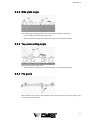
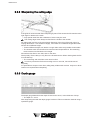
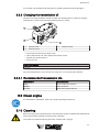
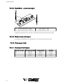
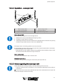
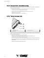
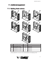
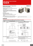
1
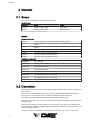
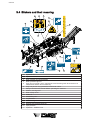
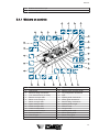
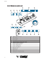
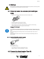
Operating Instructions
Spaltfix K-550
D1010416 - Edition - 1001
*D1010416-1001*
English
Copyright by Posch Gesellschaft m.b.H., Made in Austria
Manufacturer
Manufacturer
POSCH Gesellschaft m.b.H.
Paul-Anton-Keller-Strasse 40
A-8430 Leibnitz
Tel.: +43 (0) 3452/82954
Fax: +43 (0) 3452/82954-53
E-mail: [email protected]
http://www.posch.com
© Copyright by POSCH Gesellschaft m.b.H., Made in Austria
Please be sure to fill this in before starting. Then you can be sure that this document relates
to your machine, so if you have any queries you will be given the correct information.
Machine number:..............................................................................
Serial number:.....................................................................................
POSCH Austria:
8430 Leibnitz, Paul-Anton-Keller-Strasse 40, telephone: +43 (0) 3452/82954, fax: +43 (0) 3452/82954-53, e-mail: [email protected]
POSCH Germany:
84149 Velden/Vils, Preysingallee 19, telephone: +49 (0) 8742/2081, fax: +49 (0) 8742/2083, e-mail: [email protected]
2
Contents
Contents
1
Foreword
5
1.1
Copyright notice
5
1.2
Liability for defects
5
1.3
Reservations
5
1.4
Definitions
5
1.5
Operating instructions
6
2
Safety information
7
2.1
Explanation of symbols
7
2.2
General safety information
7
2.3
Safety instructions for cut-splitters
8
2.4
Safety instructions for conveyor belts
8
2.5
Noise
9
2.6
Remaining risks
9
2.7
Proper use
9
2.8
Incorrect use
9
3
General
10
3.1
Scope
10
3.2
Description
10
3.3
Major machine components
11
3.4
Stickers and their meaning
12
3.5
Set-up
16
4
Start-up
17
4.1
Driven by tractor via universal joint shaft (type PZG)
17
4.2
Powered by diesel engine (Type D)
17
5
Operation
19
5.1
Work operation
19
5.2
Safety bar
26
5.3
Change splitting knife
27
6
Switching off the machine
28
7
Transport
29
7.1
Retract stabiliser feet
29
7.2
Transport position - Conveyor belt
29
7.3
Transport position - Cross conveyor
29
7.4
Raise safety bar
29
7.5
Lock log manipulator
29
3
Contents
4
7.6
Transportation using the travel gear
29
8
Checks
31
8.1
Protective guards
31
8.2
Screw fittings
31
8.3
Hydraulic lines
31
8.4
Oil level
31
8.5
Cutting equipment (harvester)
32
8.6
Chainsaw
33
9
Maintenance
34
9.1
Lubrication
34
9.2
Cutting equipment (Supercut)
35
9.3
Sharpening the saw chain
36
9.4
Changing the chain
39
9.5
General chain care
40
9.6
Replacing the guide bar
40
9.7
Replacing chainwheel
41
9.8
Oil changing
41
9.9
Diesel engine
43
9.10
Cleaning
43
10
Special equipment
45
10.1
Stabiliser feet
45
10.2
Cross conveyor
45
10.3
Conveyor belt
46
11
Additional equipment
49
11.1
Splitting blade variants
49
12
Troubleshooting
50
13
Technical data
51
14
Service
52
EC Declaration of Conformity
53
Foreword
1 Foreword
Thank you for buying our product.
This machine has been built in conformity with applicable European standards and
regulations.
These operating instructions explain how to operate the machine safely and efficiently and
how to maintain it.
Any person entrusted with the transport, installation, commissioning, operation or
maintenance of the machine must have read and understood:
▪ the operating instructions
▪ the safety instructions
▪ the safety information given in the individual chapters.
To avoid operator error and ensure problem-free operation, the operating instructions must
be available to the operating personnel at all times.
1.1 Copyright notice
All documents are protected by the law of copyright.
Documents including excerpts thereof may not be distributed or reproduced nor may their
content be communicated without express permission.
1.2 Liability for defects
Read these operating instructions through carefully before putting the machine into
operation.
We accept no liability for damage or disruptions caused by failure to observe the operating
instructions.
Claims for liability must be reported as soon as the defect is identified.
Claims are null and void for example in the following cases:
▪ improper use
▪ faulty attachments and drives not supplied with the machine
▪ failure to use original spare parts and accessories
▪ conversions or modifications, where not agreed with us in writing
We are not liable for defects of wearing parts.
1.3 Reservations
Technical data, dimensions, illustrations of the machine and safety standards are subject
to continual change and are therefore not in any circumstances binding in relation to the
supplied machine.
We accept no liability for printing and typesetting errors.
1.4 Definitions
Operator
The operator is the party which operates the machine and uses it for its intended purpose
or causes it to be operated by suitable, trained personnel.
Operating personnel
5
Foreword
The operating personnel (operators) are those entrusted by the operator to operate the
machine.
Technical personnel
Technical personnel are persons entrusted by the operator of the machine with special tasks
such as installation, set-up, maintenance and troubleshooting.
Electrician
An electrician is a person who, by virtue of his specialist training, has knowledge of electrical
systems, standards and regulations and is able to identify and prevent possible hazards.
Machine
The term machine replaces the commercial designation of the object to which these
operating instructions relate (see cover sheet).
1.5 Operating instructions
This manual is a "translation of the original operating manual"
6
Safety information
2 Safety information
2.1 Explanation of symbols
The following symbols and instructions in this manual provide warnings about possible
personal injury or property damage or give useful information about working with the
machine.
DANGER
Warning about danger zones
Instruction regarding safe working, where non-compliance entails the risk of serious or
fatal injury.
Always observe these instructions and ensure that you work with particular caution and
care.
DANGER
Crushing hazard
Risk of injury through upper limbs getting trapped.
NOTICE
Instruction
Symbol for proper use of the machine.
Non-observance can result in malfunctions by or damage to the machine.
Noise
Symbol for an area where noise levels can exceed 85 dB(A).
Non-observance can cause hearing problems or deafness.
Further information
Symbol for further information relating to a bought-in part.
Information
Action-related information.
2.2 General safety information
The machine may only be operated by persons who are familiar with the machine's
operation and hazards and with the user manual.
▪ It is the operator's responsibility to provide appropriate staff training.
Persons under the influence of alcohol, drugs or pharmaceutical products that impair
responsiveness must not operate or maintain the machine.
7
Safety information
The machine may only be operated if it is in perfect working condition.
Only operate the machine if it is in a stable position.
Minimum age of operative: 18 years.
Only one person may operate the machine at a time.
Take regular breaks to ensure concentration.
Ensure that your workplace is adequately illuminated since poor lighting can significantly
increase the risk of injury.
Never work without the protective guards in place.
Only carry out repair, setup, maintenance and cleaning work when the drive is switched off
and the tool is stationary.
▪ If the machine has a PTO drive, the universal joint shaft must be removed from the
tractor.
Never leave the machine running unattended.
Switch off the machine's drive unit before carrying out any adjustments.
Only use original - POSCH - spare parts.
Do not modify or tamper with the machine.
Machines with combustion engines:
DANGER
Carbon monoxide formation
Suffocation hazard
a) Never operate machines in confined spaces!
2.3 Safety instructions for cut-splitters
Do not remove offcuts or other parts of the workpiece from the cutting area while the
machine is running.
Never reach towards the chainsaw with gloves.
Only use the machine outdoors.
▪ Should the machine be used indoors, however, a local extractor unit (extraction at
source) is required.
The machine must always be properly maintained and must be kept free of waste material
such as chips and sawn-off pieces of wood.
Wear safety shoes and close-fitting clothes when working with this device.
Wear protective gloves.
Use respiratory protection to reduce the risk of inhaling harmful dust.
When turning off the machine, always be careful of the tool runout until the machine has
come to a standstill.
The working pressure of the hydraulic system must not exceed 300 bar.
2.4 Safety instructions for conveyor belts
Persons must keep clear of the danger zone.
It must be expected that material will be ejected at high speed to any position within this
area.
Never reach into the hopper or touch the conveyor belt when the machine is running.
Shut the drive down before removing any jammed pieces of wood.
Only use the machine outdoors.
8
Safety information
Wear safety shoes and close-fitting clothes when working with this device.
Wear protective gloves.
The working pressure of the hydraulic system must not exceed 300 bar.
2.5 Noise
In machines with an internal combustion engine an A-rated emission sound pressure level
of 95 dB(A), measured at the operative's ear, should be expected.
The workplace-related, A-rated emission sound pressure level is
▪ 80 dB(A) when idling or
▪ 95 dB(A) when sawing,
measured at the operative's ear.
In the case of machines with a PTO drive, the noise level depends on the noise of the tractor.
Ear protection is therefore necessary.
The stated values are emissions values, and thus do not necessarily represent reliable
values for the work area. Although there is a correlation between emission and pollutant
levels, it is not possible to deduce reliably from that whether or not additional precautionary
measures are necessary. Factors that influence the level of pollutants present in the work
area include the individual nature of the work area, other sources of noise, e.g. the number
of machines and other work operations being carried out in the vicinity. Equally, permissible
values for a work area may vary between different countries. However, this information
should enable the user to estimate the dangers and risks more accurately.
2.6 Remaining risks
Even if all safety precautions are observed and the machine is used in accordance with the
instructions, some risks still remain:
▪ Touching of revolving parts or tools.
▪ Injury caused by flying logs or log pieces.
▪ Risk of burns if the engine is not properly ventilated.
▪ Hearing loss if ear protection is not worn when working.
▪ Human error (e.g. due to excessive physical exertion, mental strain, etc.)
With every machine, some risks still remain. Therefore you should always be very careful
when working. It is up to the operating personnel to ensure that work is carried out safely.
2.7 Proper use
The Spaltfix K-550 is a cutting and splitting machine for logs with a diameter of 10 - 55 cm.
It splits logs with a splitting force of 36 t or 41 t into 2 to 18 sections. The section length is
adjustable from 25 - 100 cm.
The machine may only be used to process firewood.
2.8 Incorrect use
Any incorrect use or use other than that specified under "Proper use" is expressly forbidden.
9
General
3 General
3.1 Scope
This user manual applies to the following machines:
Machine type
Item no.*
M3705
M3745
Type
Spaltfix K-550 - PZG
Spaltfix K-550 - D100
Drive
PTO shaft
Diesel engine
*The article number is stamped on the machine's rating plate.
Models
Special equipment
SO380
SO390
SO381
SO384
SO438
SO385
SO389
Tractor chassis, 10 km/h with hydraulic stabiliser feet
Tractor chassis, 10 - 25 km/h with hydraulic stabiliser feet and air brake
system
Road chassis, 80 km/h with hydraulic stabiliser feet and ABS brake
system
Conveyor belt 2.5 m, hydraulic drive
Conveyor belt 3.5 m, hydraulic drive
Conveyor belt 5 m, hydraulic drive
Conveyor belt 6 m, hydraulic drive
Additional equipment
F0002549
Tank heating
F0001678
Splitting knife, 4-section
F0001674
6-billet splitting blade
F0001694
8-billet splitting blade
F0001679
Ring splitting knife 210, 12-section
F0001680
Ring splitting knife 250, 15-section
F0001672
Ring splitting knife 250, 18-section
F0001673
Ring splitting knife 300, 18-section
3.2 Description
The Spaltfix K-550 machine is a firewood processing machine which is used to cut and then
split firewood.
The log is cut in a horizontal position and is held in place with the claw while being cut.
The log is then cut to length by the hydraulically driven Harvester chainsaw.
The chainsaw is lubricated with chainsaw oil during the cutting process.
Once the log has been cut, it is tipped forwards by the tilting mechanism and drops into the
splitting trough.
The ram of the hydraulic splitter advances and presses the log against the splitting knife.
The hydraulically height-adjustable splitting knife allows the optimum setting to be achieved
in any operating situation.
A choice of options is available for discharging the split logs, e.g. via a conveyor belt.
10
General
Operation of the hydraulic ram is semi-automatic.
The cutting and splitting tool is hydraulically driven.
The machine is driven by a pto or a diesel engine.
3.3 Major machine components
11
12
10
10
9
8
7
6
5
4
3
2
1
13
14
15
16
17
18
19
20
21
22
23
26
1
2
3
4
5
6
7
8
9
10
11
12
13
25
24
Wood trough
Chain conveyor
Hydraulic tank
Rating plate
Chainsaw oil tank
Controls
Guard bar
Chainsaw
Claw
Log diameter display
Safety grille
Conveyor belt
Belt conveyor stabiliser foot
14
15
16
17
18
19
20
21
22
23
24
25
26
Light barrier
Splitting knife
Tilting mechanism
Splitter
Base
Wheel
Diesel engine switchgear cabinet
Controller switchgear cabinet
Steps
Diesel engine
Hydraulic stabiliser foot
Base frame
Drawbar
11
General
3.4 Stickers and their meaning
7
6
8
11
Z2001157
10
5
10
20
2
Z205 0400
9
12
30
4
40
Z205 0679
50
55
Z200 1360
3
Z200 1256
Z205 0561
1
Z200 1260
11
13
14
Z205 0400
Z200 1173
Z200 1162
max. 8,5 bar
16
5
m
18
Z204 0385
-1
n = 440 min
16
min
15
-1
n = 480 min
max
Z200 1240
1
2
3
4
5
6
7
8
9
10
11
12
13
14
15
16
12
Z200 1220
Hydraulic oil
Hydraulic oil level
Wear goggles and ear defenders
Wear protective gloves
Only carry out repair, setup, maintenance and cleaning work when the drive is
switched off and the tool is stationary.
Only one person may operate the machine at a time
Always read the user manual before operating the machine
Caution, moving tools
Wear safety shoes
Chain oil
Lubrication point
Log diameter
Grease tool guide
Danger zone (at belt conveyor)
Tyre pressure
Operation - stabiliser feet
General
17
18
Rotational direction of pto
Maximum pto speed
3.4.1 Stickers on controls
5
1
2
7
6
8
4
3
9
10
28
Z200 1231
11
27
12
26
13
Z200
Z200 1229
1229
25
14
15
24
23
1
2
3
4
5
6
7
8
9
10
11
12
13
14
22
21
Advance cross conveyor chain
Claw to left
Advance tilting mechanism
Lock claw advance (on lever)
Retract conveyor belt
Raise cross conveyor
Raise conveyor belt
Open conveyor belt
Close conveyor belt
Lower conveyor belt
Lower cross conveyor
Conveyor belt on
Claw to right
Saw
20
19
15
16
17
18
19
20
21
22
23
24
25
26
27
28
18
17
16
Lock claw (on lever)
Retract cross conveyor chain
Log manipulator downwards
Split
Splitting knife downwards
Safety grille downwards
Retract tilting mechanism
Splitting knife to right
Shorter wood
Longer wood
Splitting knife to left
Raise splitting knife
Raise safety grille
Raise log manipulator
13
General
3.4.2 Stickers on control unit
5
1
2
6
7
4
3
B
Z2001194
Z204 0380
A
Z2001193
8
9
10
Z204 0375
11
Z204 0370
12
1
2
3
4
5
6
7
8
9
10
11
12
13
14
15
16
14
13
Splitter - manual/automatic
Start machine
Advance splitter
Retract splitter
Operating pressure of splitter (on ram side)
Operating pressure of splitter (2nd cylinder)
Operating pressure of chainsaw
Counter - splitting operations
Control voltage present
Counter - operating hours
Speed of saw advance
Safety loop - OK
Splitter at front
Splitter at rear
Splitting knife in adjustment range
Default position - tilting mechanism
14
15
16
General
3.4.3 Labels on the cross-conveyor
Z205 0400
1
Z200 1204
Z200 1246
3
max.
1,5 t
1
1m
2
Z205 0400
1
2
3
Lubricating point
Maximum weight load
Danger zone
3.4.4 Stickers on belt conveyor
1
2
Z200 1246
Z205 0400
.3
max
3
5˚
Z200 1206
15
General
1
2
3
Lubrication point
Danger zone
Max. angle of conveyor belt
3.5 Set-up
Ensure the machine is stable before starting it.
Set up the machine on a level, firm and clear work surface.
The machine must be placed directly on the ground. Do not place wooden boards, flat pieces
of metal etc. underneath it.
3.5.1 Lower stabiliser feet
Please see ... Stabiliser feet [➙ 45]
3.5.2 Working position - Conveyor belt
▪ See: Conveyor belt [➙ 46]
3.5.3 Working position - Cross conveyor
▪ See: Cross conveyor [➙ 45]
3.5.4 Unlock log manipulator
Please see ... Log manipulator [➙ 22]
3.5.5 Lower safety bar
Please see ... Safety bar [➙ 26]
16
Start-up
4 Start-up
Before starting to operate the machine, please check that the protective and safety systems
are working and also the hydraulic hoses and oil level.
4.1 Driven by tractor via universal joint shaft (type
PZG)
▪ Attach the universal joint shaft and secure with the safety chain.
▪ Clockwise rotation of the tractor PTO shaft.
▪ Turn the tractor's manual throttle to minimum.
▪ Slowly engage the tractor PTO shaft and allow the machine to start moving.
▪ Set the required PTO speed using the manual throttle.
Maximum PTO shaft speed:
▪ 480 rpm
The maximum PTO shaft speed must on no account be exceeded, otherwise the oil will
become too hot. This leads to premature wear and leaks in the pump, cylinder and hydraulic
pipes.
Before disengaging the universal joint shaft, set the manual throttle of the tractor to
minimum.
The universal joint shaft must be stored in the universal joint shaft linkage when it is
disconnected.
4.1.1 Connecting the power supply
▪ Connect the 7-pin plug to the tractor.
Supply voltage 12 V
16 A continuous current
▪ 20 A continuous current for machines with crane
▪ Switch on lights on tractor (depending on model).
4.2 Powered by diesel engine (Type D)
Check the oil level before starting the engine.
17
Start-up
4
6
3
OFF
ON
START
1
5
1
2
3
2
Mode switch
Speed regulator
Ignition switch
4
5
6
Preheat indicator
Fuel gauge
Engine display
1. Insert and turn on the battery main switch.
– This is located in the engine compartment on the battery cover plate.
2. Set the mode switch to "Manual".
3. Set the speed regulator to "Minimum".
4. Turn the ignition switch to "ON".
– Preheating takes place automatically (indicator lights up).
5. When the indicator goes off, turn the ignition switch to "Start".
6. When the engine starts, let go of the ignition switch.
7. Set the desired speed with the speed regulator or switch to "Automatic mode".
– In automatic mode the engine automatically goes to maximum speed when a
hydraulic function is activated.
Engine information:
Engine
Fuel
Tank capacity
D100
diesel
180 litres
Consumption
approx.
8 to 10 l/h
For further information, refer to the operating instructions supplied with the engine.
18
Operation
5 Operation
At outdoor temperatures below 0°C, let the machine idle for approximately five minutes
to allow the hydraulic system to reach the correct operating temperature (the hydraulic pipes
will then be warm to the touch).
5.1 Work operation
Only one person may operate the machine at a time.
Ensure that no other people are in the vicinity of the machine.
1. Start the machine.
2. Turn on the main switch at the switch cabinet.
– See: Switch cabinet [➙ 23]
3. Turn on the controller ("Start system").
– See: Control box [➙ 24]
5.1.1 Operation of claw, saw and tilting mechanism
1
4
2
3
1
2
Tilt
Claw - left
3
4
Saw
Claw - right
▪ Using the control lever (Claw - right) move the log as far as the wood stop.
▪
There are also additional functions available at the control lever:
– If you press the right tilt key, the claw advance is locked (to hold the log more firmly).
– If you press the left tilt key, the claw is locked (to retract the log).
▪ Pull the control lever towards you (Saw) and saw through the log.
The chain is lubricated with chainsaw oil at the same time.
Never work without chain lubricating oil.
▪ Hold the lever towards you until the log has been completely sawn through.
The saw advance rate can be adjusted to the wood being cut.
▪ Please see Set saw advance rate [➙ 21]
▪ Use the control lever (Tilt) to move the sawn log to the splitting area.
Ensure that the log is configured longitudinally to the splitting knife.
19
Operation
5.1.2 Operating the splitter and splitting knife
4
1
3
5
2
1
2
3
Splitting knife - up
Splitting knife - down
Split
4
5
Splitting knife - retract
Splitting knife - advance
▪ Use the control lever (Split) to initiate a splitting stroke (push the lever briefly to the right).
The log is pressed against the splitting knife and split.
▪
There are also additional functions available at the control lever:
– If you press the left tilt button, the roll grille opens (e.g. to align the log).
– If you press the right tilt button, the roll grille closes.
The splitting knife can be adjusted (to set the split centre point).
▪ Read off the log diameter at the claw and set using the control lever (Splitting knife - up/
down) according to the scale at the splitting knife.
▪ Set the centre point of the splitting knife from the side adjustment area using the control
lever (Advance/retract splitting knife).
20
Operation
5.1.2.1 Left-over wood
1
1
Retract tilting mechanism
If the left-over wood is too short to split, it can be ejected to the rear using the tilt function.
Eject the left-over wood by pressing the control lever (1) to the left.
Machines with a crane do not have a left-over wood ejection facility.
5.1.2.2 Notes on splitting
Only use logs up to a diameter of 10 - 55 cm.
Remove jammed wood from the splitting blade with a striking tool.
5.1.3 Set saw advance rate
-
+
▪ Increase advance rate: Turn the throttle anti-clockwise.
▪ Reduce the advance rate: Turn the throttle clockwise.
21
Operation
5.1.4 Set log length
1
2
1
Long log
2
Short log
The log length is infinitely variable within the range 25 - 100 cm.
Set the desired log length using the control lever (Long/short log).
▪ The log length can be read off on the length scale.
Machines with conveyor belt:
For log lengths in excess of 50 cm the conveyor belt must be lowered until it is horizontal
to prevent damage to the conveyor belt.
Where the log length exceeds 50 cm only 4-, 6- and 8-section splitting knives may be used.
5.1.5 Log manipulator
1
2
22
Operation
1
Log manipulator arm
4
Lock
Working position:
Rotate the lock to the rear until it engages.
Transport position:
Rotate the lock to the front until it engages.
The log manipulator arm is secured against accidental lowering.
Log manipulator operation
1
2
1
Retract log manipulator arm
2
Advance log manipulator arm
Use the control lever (Advance/retract log manipulator arm) to move the log to the right
position.
5.1.6 Electrical functions
5.1.6.1 Switchgear cabinet
2
8
9
7
6
4
5
3
1
1
2
Master switch
LED - control voltage present
6
7
3
4
5
LED – safety loop OK
LED – splitting knife position
LED – splitter at rear
8
9
LED – splitter at front
LED – tilting mechanism default
position
Counter - splitting operations
Counter - splitting operations
The following functions are available on the front of the switchgear cabinet:
▪ The master switch (1) for supplying power to the 12 V electrics.
23
Operation
▪ LED (2) lights up if the 12 V power supply is available.
▪ LED (3) lights up if the safety loop is available.
– The loop is closed if no emergency stop function has been actuated.
▪ LED (4) lights up if the splitting knife is in the range of the side adjustment.
– This position is monitored to prevent damage to the splitting knife or mount.
▪ LED (5) lights up if the splitter is at the rear.
▪ LED (6) lights up if the splitter is at the front.
▪ LED (7) lights up if the tilting mechanism is in the centre position.
– If it is not in this position, no splitting stroke is initiated.
▪ The counter (8) counts the splitting operations performed by the machine.
▪ The counter (9) counts the operating hours worked by the machine.
5.1.6.2 Control unit
1
2
3
1
2
4
Switch - manual/automatic splitter
operation
Button (green) - start machine
3
Button (yellow) - retract splitter
4
Button (yellow) - advance splitter
The control unit has one switch and 3 buttons:
Press button (2) to switch the electrical system on.
▪ The button lights up green; if not, see page [➙ 25].
You can choose between operating the splitter in manual or automatic mode with switch
(1).
▪ Manual mode: In manual mode you can move the splitter in stages using buttons (3)
and (4), e.g. if a log is jammed.
▪ Automatic mode: Once you have actuated the (Split) [➙ 20] control lever, the splitter
automatically advances to its end position and then retracts to its starting position.
24
Operation
5.1.6.3 Stop function
3
2
1
1
2
Stop button
Roll grille
3
5
Guard bar
The machine has 3 Stop functions.
Actuating the Stop function switches off all safety-related drives.
This affects the:
▪ Chainsaw
▪ Splitter
1st stop function: by operating the Stop button on the control panel.
2nd stop function: by opening the splitter system roll grille.
3rd stop function: by raising the safety bar at the rear of the machine.
Before you can continue working with the machine, the Stop function must first be
deactivated:
▪ Unlock the Stop button, close the roll grille, lower the safety bar.
▪ Press the (Start machine) [➙ 24] button - button lights up green - machine is ready.
5.1.6.4 End switches
The inductive end switches have an LED for monitoring purposes.
▪ Green LED ..... 12 V control voltage present
▪ Yellow LED ..... switching state - on
5.1.6.5 Malfunctions
Fault
No 12V supply voltage present
Machine cannot be switched on
Splitter does not advance
The inductive end switches do not light up
Cause
With type PZG, plug not connected to tractor
Fuses (F1/F2) in switchgear cabinet faulty
Supply cable to switchgear cabinet faulty
No 12V supply voltage present
Check safety end switches (emergency stop
button, roll grille, safety bar) for contact and
cable break
Tilting mechanism not in centre position
Splitting knife not in adjustment range of
side adjustment
No 12V supply voltage present
25
Operation
Fault
Cause
End switch(es) not set correctly (gap 3 – 5
mm)
End switch(es) faulty or cable break
5.2 Safety bar
1
3
2
4
1
2
Cross conveyor
Clip pin
3
4
Safety bar
Cotter pin
Lower safety bar:
1. Lower the cross conveyor.
2. Release the right clip pin.
3. Raise the safety bar slightly and withdraw the cotter pin.
4. Lower the safety bar as far as the stop.
Raise safety bar:
▪ Proceed as described above but in reverse order.
26
Operation
5.3 Change splitting knife
6
5
3
4
2
1
1
2
3
Piece of wood
Cylinder screw
Cylinder
4
5
6
Connecting panel
Lift bracket
Eye
1. Place a piece of wood under the splitting knife.
2. Lower the splitting knife onto the wood.
▪ The piece of wood should be high enough to ensure that the cylinder screw is in the
centre of the slot.
1. Remove the connecting panel by releasing the 4 screws.
2. Loosen the 4 screws on the lift bracket.
3. Pull the entire lift bracket forwards.
4. The splitting knife can be withdrawn upwards by connecting a crane or front loader etc.
to the lifting eye.
Grease the new splitting knife before fitting it.
27
Switching off the machine
6 Switching off the machine
Before switching off the machine, depressurise all hydraulic functions
by placing all control levers in the neutral position.
Driven by tractor via cardan shaft (type PZG)
Disengage the cardan shaft on the tractor.
▪ Before disengaging, turn the manual throttle to minimum.
Powered by diesel engine (Type D)
Set the diesel engine to idle and let it run for a few minutes to allow the engine to cool down,
then switch it off (see engine operating instructions).
28
Transport
7 Transport
7.1 Retract stabiliser feet
Please see ... Stabiliser feet [➙ 45]
7.2 Transport position - Conveyor belt
▪ See: Conveyor belt [➙ 46]
7.3 Transport position - Cross conveyor
▪ See: Cross conveyor [➙ 45]
7.4 Raise safety bar
Please see ... Safety bar [➙ 26]
7.5 Lock log manipulator
Please see ... Log manipulator [➙ 22]
7.6 Transportation using the travel gear
Tractor travel gear
▪ Attach the towbar to the tractor.
▪ Crank up the jockey wheel.
▪ Release the parking brake.
▪ Check tyre pressure - max 3.5 bar.
▪ Plug the lighting system plug into the tractor.
▪ Check that the lighting system is working properly.
Observe the road traffic regulations when driving on public highways.
Maximum transport speed: 6 km/h (10 km/h) - Observe local regulations.
When the machine is uncoupled from the tractor, it must be placed on a firm, level
surface.
29
Transport
Lorry travel gear
▪ Attach the towbar to the tractor.
▪ Crank up the jockey wheel.
▪ Plug the lighting system plug into the tractor.
▪ Check that the lighting system is working properly.
▪ Check tyre pressure - max 3.5 bar.
Observe the road traffic regulations when driving on public highways.
Maximum transport speed: 80 km/h
When the machine is uncoupled from the tractor, it must be placed on a firm, level
surface.
30
Checks
8 Checks
Before carrying out any checks on the machine, the drive unit MUST be switched off!
8.1 Protective guards
All the protective guards (covers, safety grilles, etc.) must be in place.
8.2 Screw fittings
Tighten all screws and nuts after the first hour of operation.
Tighten the screws and nuts after every 100 hours of operation.
▪ Replace missing screws and nuts.
8.3 Hydraulic lines
After the first hour of operation, check that all hydraulic connections are secure and are not
leaking.
Check that all hydraulic connections are secure and are not leaking after every further 100
hours of operation.
▪ Damaged hydraulic lines must be replaced immediately.
8.4 Oil level
To check the oil level place the machine on an even surface.
Check the oil level with the pusher retracted.
8.4.1 Hydraulic oil level
When the oil sight glass is filled above halfway, the oil level is at its maximum.
When the oil level is towards the bottom of the oil sight glass, the oil level its at its minimum.
If this is the case, the hydraulic oil must be topped up immediately.
▪ See: Changing the hydraulic oil [➙ 41]
The oil filter only needs to be checked when the oil is changed.
8.4.2 Chain lubrication oil
Never work without chain lubrication.
The oil level can be monitored as the tank is transparent.
31
Checks
Recommended chain lubrication oil:
Manufacturer
Fuchs
Type
Plantotac Bio
Total filling capacity
30 litres , 13 litres (for machines with crane)
Any other biologically degradable chain lubrication oil can be used, provided it is of the
following viscosity:
▪ 50 - 75 at 40° C
▪ 10 - 20 at 100° C
8.4.3 Transmission oil level
1
2
3
1
2
Oil inlet screw
Oil level screw
3
Oil drain screw
If the oil seeps out of the hole of the oil level screw when the machine is on level ground,
the maximum oil level has been reached.
If the oil level is below the hole, this is the minimum oil level.
If this is the case, the transmission oil must be topped up immediately.
▪ See: Changing the transmission oil [➙ 43]
8.5 Cutting equipment (harvester)
Daily:
▪ Fastenings and hydraulic hoses.
▪ That no damage or breakages have occurred to the saw unit.
▪ Saw chain check.
▪ Chain lubrication oil tank level check.
Check every 8 - 20 operating hours, regardless of operating conditions:
32
Checks
▪ Saw unit lubrication at lubrication point with mineral-oil-based grease.
8.6 Chainsaw
8.6.1 Saw chain
Check the cutting performance of the chain.
▪ If the chain is not properly sharpened, cutting performance will be compromised.
▪ Dull chains produce sawdust, sharp chains produce chips.
Posch chainsaw:
The chain tension should be such that the chain can be raised by 4-5 mm in the centre of
the chain bar.
Supercut chainsaw:
Chain tension is established automatically during operation.
8.6.2 Chainwheel
If the chain wheel shows signs of digging-in on the teeth it requires replacing. Otherwise
the service life of the chainsaw will be reduced.
33
Maintenance
9 Maintenance
Before carrying out any maintenance on the machine, the drive unit MUST be switched off!
Never work without the protective guards in place.
Only use original - POSCH - spare parts.
9.1 Lubrication
Dispose of oily and greasy parts and oil residues in accordance with legal regulations.
9.1.1 Lubrication schedule
C
A
B
E
D
F
1
2
3
1..........Mineral oil grease, 2..........Multi-purpose grease, 3..........Spray oil
Lubrication intervals
Daily
Weekly (every 40 operating
hours - or less depending on
application)
34
Item
A
B
C
What/where
Guides on the splitter (central lubricating
header)
Cutting head on saw unit
All lubricating points on the gripper
Maintenance
Lubrication intervals
Item
D
What/where
The sliding surfaces on the splitting blade
adjuster
E
On the feed table, the cylinder mounting and the
feed table mounting
F
The housing bearings and chainwheels on the
cross conveyor
not
The cylinder mounting and the housing bearings
illustrated on the conveyor belt
Monthly (every 160
operating hours - or less
depending on application)
The lubrication points are marked with the lubricate symbol.
Recommended lubricating greases:
Manufacturer
Genol
Fuchs
Type
Multi-purpose grease
Multi-purpose grease 5028
9.2 Cutting equipment (Supercut)
9.2.1 Cleaning the check-valve (outlet)
1
2
3
1
2
Check-valve key
Check-valve
3
Lubricating oil pump
1. Remove hose and elbow fitting from the lubricating oil pump.
2. Remove the check-valve with the check-valve key.
3. Check the check-valve for deposits and clean or replace if necessary.
4. Ensure that there is no dirt in the lubricating oil pump.
5. Refit the check-valve.
6. Fit the hose and elbow fitting back on.
35
Maintenance
9.2.2 Cleaning the inlet filter and check-valve (inlet)
1
2
3
4
5
1
2
3
Filter
Compression spring
Plug
4
5
Check-valve (inlet)
Allen key 4 mm
1. Remove hose from the plug.
2. Undo plug using a 32 mm screwdriver.
3. Remove compression spring and filter.
4. Clean or replace filter if necessary.
5. Undo the check-valve (inlet) with a 4 mm Allen key and take it out.
6. Clean the check-valve or replace if necessary.
7. Refit the removed components.
8. Replace hose.
9.3 Sharpening the saw chain
When sharpening the chain the following dimensions should be borne in mind to achieve
optimum chain sharpness.
The following dimensions refer to the chain used on this machine.
▪ Oregon 18HY-86E
Only use a chain and guide bar made by the same manufacturer.
9.3.1 Top plate angle
The top plate angle is 35°.
This must be the same on all cutting teeth.
DIfferent cutting angles can lead to a raw, uneven chain action and increased wear on
the chain.
36
Maintenance
9.3.2 Side plate angle
The cutting edge sloping away from the tooth point is called the side plate.
▪ On the Oregon chainsaw this angle is 85°.
▪ When sharpening using the file guide this angle is automatically created.
9.3.3 Top-plate cutting angle
The top plate cutting angle is 60°.
▪ When sharpening using the file guide this angle is automatically created.
9.3.4 File guide
When sharpening the file must be parallel to the tooth point and moved at an angle of 110°
to the side of the chain links.
37
Maintenance
9.3.5 Sharpening the cutting edge
A file guide is recommended when sharpening by hand. This ensures the file remains at the
right angle in relation to the tooth.
▪ Only special chain files with a diameter of 5.5mm may be used.
The cutting edges must always be filed from the inside to the outside.
All cutting teeth must be of the same length. Because of the form of the tooth point (i.e.
sloping downwards - front clearance angle), if the teeth are of different lengths then teeth
will also be of different height.
▪ Teeth of different heights can lead to a rough chain action and possible chain breaks.
▪ The shortest tooth must therefore be measured and sharpened first. The remaining
teeth must then be filed back to this length.
All teeth are first filed on one side, then on the other.
Work quickly. Ensure that you only file on the forwards stroke. When drawing back the file
must be lifted up.
▪ The connecting and drive links must never be filed.
In order to prevent the file from becoming worn on one side, it should be turned
frequently.
It is preferable to sharpen more often, taking away a little metal at a time. Only two or three
strokes are required when sharpening.
9.3.6 Depth gauge
The depth gauge determines the depth of bite into the wood, i.e the thickness of chips.
▪ The depth is 1.2 mm.
After sharpening the teeth the depth gauge is reduced. This must then be checked using a
special file gauge.
38
Maintenance
If the depth extends over the file gauge it must be filed back using a flat or triangular file.
9.3.7 Automatic chain sharpeners
Automatic chainsaw sharpeners can be purchased at your specialist dealer. These offer
precise chain sharpening.
9.4 Changing the chain
6
1
5
2
7
3
4
1
2
3
4
Guide bar
Locking button
Slackening button 1
Chainwheel
5
6
7
Guide screw
Chain
Slackening button 2
Wear protective gloves when working on the chainsaw to prevent cuts.
1. Press the slackening button 1 (lower button on rear) and the slackening button 2 (on
the right of the plate) at the same time to slacken the chain.
2. Pull on the chain.
– The guide bar is slackened.
3. Press the locking button (top button on the rear) and pull on the chain until the locking
button clicks into place.
4. Now the chain can be removed.
5. Blow out the oil supply holes and the chain rail in the guide bar with compressed air.
6. Check the depth of the chain rail.
39
Maintenance
– The minimum depth for the chain rail is 7 mm. This prevents the drive links from
grinding on the base of the rail.
– If this the depth falls below this minimum the guide bar must be replaced.
7. Reinstall the guide bar, having turned it round 180°. This prevents the guide bar from
becoming worn on one side, as it is exposed to the most wear on the underside.
8. Place the new chain on the guide bar.
– New chains should never be placed on a broken-in (used) chainwheel.
– The chainwheel must be changed after a maximum of two chains.
Recommended chains: Oregon 18HY-86E
Drive link thickness: 2 mm
Number of drive links: 86
Before fitting the chain, soak it overnight in lubricating oil, allowing it to penetrate
all links.
Ensure that the cutting edges of the parts on the upper side of the rail point towards the
guide bar head.
9. Pull on the chain briefly, so that the chain locking button clicks into place and release
the chain slowly back onto the guide bar.
– Chain tension is established automatically during operation.
9.5 General chain care
Before fitting a new chain, soak it overnight in lubricating oil, allowing it to penetrate all links.
After sharpening clean the chain thoroughly in petrol to remove any swarf caused by filing.
Then lubricate the chain in an oil bath.
When cleaning or sharpening check the chain for tears in the links or damaged rivets.
Replace any damaged or worn parts.
▪ The new parts must be of the same size and format as the existing chain parts.
During long periods of disuse the chain should be cleaned with a brush and placed in an
oil-petroleum bath.
Each new chainsaw requires a short running-in time of approx. 2-3 minutes before cutting
work can begin.
9.6 Replacing the guide bar
1. Remove the chain.
2. Undo the guide screws on the rail holder and remove the guide bar.
3. Fit a new guide bar and retighten guide screws.
40
Maintenance
9.7 Replacing chainwheel
Nord-Lock !
4
3
2
1
1
2
Acorn hexagon head bolt
Nord-Lock washer
3
4
Chain catcher
Chainwheel
1. Remove the chain.
2. Undo the acorn hexagon head bolt.
3. Remove the Nord-Lock washer and the chain catcher.
– The chainwheel can now be removed.
4. Fit the new chainwheel.
5. Carefully clean the acorn hexagon head bolt and the threaded hole in the shaft or the
saw engine.
6. Apply some "Loctite 243" to the acorn hexagon head bolt.
7. Fit the chain catcher back on and tighten the acorn hexagon head bolt with the NordLock washer.
It is essential to use the Nord-Lock washer – no other type of lock washer must be
used.
9.8 Oil changing
Old oil must be disposed of in an environment-friendly manner. Find out about the
environmental regulations in your country.
9.8.1 Changing the hydraulic oil
Carry out the first oil change after 500 hours of operation. Thereafter change the oil at least
once per year.
An oil change is not required any earlier as we carry out a secondary flow filtration
during the final check where all dirt particles are removed.
▪ Cleanliness test in line with ISO 4406: cleanliness class 14/11 fineness 1.2 ym / oil load
- low.
Changing procedure:
▪ Retract the pusher before changing the oil.
41
Maintenance
▪ Open the filler cap.
▪ Open the oil drain screw.
The oil drain screw is located on the base of the oil tank.
▪ Drain the old hydraulic oil into a container.
▪ Screw the oil drain screw back into the tank and fill with new hydraulic oil.
▪ Turn on the machine and allow it to run for a short while.
▪ Check the oil level and top up hydraulic oil if necessary.
Total filling capacity of the hydraulic system:
Quantity
350 litres
Our hydraulic system is filled with high-quality OMV ATF II transmission fluid.
▪ This oil has an extremely high viscosity index, exhibits excellent foaming and aging
characteristics and excellent flow properties at low temperatures and protects reliably
against wear and corrosion.
▪ Viscosity class ISO VG 46.
This high-quality oil comes highly recommended when changing the oil.
A mixture of products of the same quality poses no problem.
9.8.1.1 Recommended hydraulic oils
Manufacturer
OMV
SHELL
ELF
ESSO
CASTROL
ARAL
GENOL
FUCHS
Oil specification
ATF II
Donax TA
Hydrelf DS 46
Univis N46
Hyspin AWH-M 46
Vitam VF46
Hydraulic oil 520
Platohyd 32S * / Renolin B46 HVI
*.....biological hydraulic oils
9.8.2 Oil filter
1
2
1
Filter cover
2
Filter insert
The filter insert should be changed every time the oil is changed.
Any aluminium particles can be disregarded, as these occur when the pump is running in.
42
Maintenance
Do not wash out the filter insert with petrol or paraffin products as these damage it.
9.8.3 Changing the transmission oil
The first oil change should be carried out after 100 operating hours, further oil changes
should then be carried out every 500 operating hours or yearly.
1
2
3
1
2
Oil inlet screw
Oil level screw
3
Oil drain screw
▪ Unscrew the oil inlet and oil drain screw.
▪ Let the old oil drain out, then replace the oil drain screw.
▪ Add the new transmission oil.
▪ Check oil level.
Total filling capacity
0.5 litres
Any other transmission oil can be used, so long as it is in viscosity class SAE 90.
9.8.3.1 Recommended transmission oils
Manufacturer
OMV
GENOL
FUCHS
Oil specification
Gear Oil MP SAE 85W-90
Gear oil MP 90
Titan Gear Hypoid SAE 90
9.9 Diesel engine
For maintenance operations, refer to the engine operating instructions.
9.10 Cleaning
Before carrying out any cleaning work on the machine, the drive unit MUST be switched off!
Clean the machine regularly to ensure proper operation.
Only wash new machines (during the first 3 months) with a sponge.
43
Maintenance
▪ The paint is not yet completely set, so cleaning with a high pressure cleaner may
damage the finish.
44
Special equipment
10 Special equipment
10.1 Stabiliser feet
1
2
3
4
1
3
5
7
2
4
6
8
Raise front right stabiliser foot
Lower front right stabiliser foot
Raise front left stabiliser foot
Lower front left stabiliser foot
5
6
7
8
Raise rear right stabiliser foot
Lower rear right stabiliser foot
Raise rear left stabiliser foot
Lower rear left stabiliser foot
Lower stabiliser feet:
1. Lower the hydraulic stabiliser feet using the control levers.
2. Keep lowering until the machine is lifted off its wheels and is aligned horizontally.
Retract stabiliser feet:
Proceed as described above but in reverse order.
10.2 Cross conveyor
Several logs can be placed on the cross conveyor at once.
10.2.1 Lower cross conveyor
1. Unlock the cotter pin for the transport bracket.
– Withdraw the spring cotter for the transport bracket, pull down the cotter pin and fit
the spring cotter again.
2. Withdraw the cotter pin for the stabiliser foot.
– To do so, remove the spring cotter for the stabiliser foot.
3. Swing the stabiliser foot out and relocate the cotter pin in the bore.
– Refit the spring cotter.
4. Using the control lever, lower the cross conveyor to the ground.
45
Special equipment
10.2.2 Operation - cross conveyor
1
3
2
4
1
2
Cross conveyor chain - retract
Cross conveyor chain - advance
3
4
Cross conveyor - lower
Cross conveyor - raise
Using the control lever (Cross conveyor - advance) move the log into the claw trough.
10.2.3 Raise cross conveyor
Proceed as described above for lowering the cross conveyor but in reverse order.
10.3 Conveyor belt
10.3.1 Conveyor belt types
Conveyor belt type
2,5
3,5
5
6
46
Conveyor belt length
250 cm
350 cm
500 cm
600 cm
Conveyor height
140 cm
190 cm
260 cm
310 cm
Belt width
80 cm
80 cm
80 cm
80 cm
Special equipment
10.3.2 Operation - conveyor belt
1
3
2
4
5
6
1
2
3
Raise conveyor belt
Lower conveyor belt
Open conveyor belt
4
5
6
Close conveyor belt
Conveyor belt on
Retract conveyor belt
Open conveyor belt:
Before opening, unplug and remove the light barrier.
1. Release the conveyor belt stabiliser feet (spring cotter).
2. Actuate the control lever for opening.
3. Alternately actuate the second control lever for lowering and the control lever for opening
until the conveyor belt comes to a halt on its stabiliser feet.
The angle when in its working position must not exceed 35°.
For log lengths in excess of 50 cm the conveyor belt must be lowered until it is horizontal
to prevent damage to the conveyor belt.
▪ Raise the belt conveyor slightly, fasten the long stabiliser feet to the belt conveyor, lower
the short feet and lower the belt conveyor onto them.
Close conveyor belt:
Proceed as described above but in reverse order.
Switch conveyor belt on:
Switch the conveyor belt on using the control lever (Conveyor belt on).
10.3.3 Notes regarding the conveyor belt
Check that the belt is running centrally. The belt drive dogs must not move.
▪ If they do, the belt must be corrected so it runs centrally by adjusting the drive pulley or
return drum.
From time to time remove the material that drops down underneath the conveyor belt
to prevent damage to the belt drive dogs.
47
Special equipment
10.3.4 Conveyor belt - set central running
If the conveyor belt is not running centrally on the drive and/or tail pulleys, it is possible to
adjust the direction of travel.
▪ Slightly loosen the fastening screws on each side of the conveyor belt.
▪ Loosen the lock nuts on both tensioning screws.
▪ Align the return drum by tightening both tensioning screws evenly.
▪ Tighten the lock nuts again.
▪ Tighten the fastening screws on both sides.
10.3.5 Tension conveyor belt
1
2
3
1
2
Fastening screw
Lock nut
3
Tensioning screw
The conveyor belt may become slack over time as a result of wear and tear. If this happens,
the belt must be retensioned.
▪ Move the conveyer belt to the working position.
▪ Slightly loosen the fastening screws on each side of the conveyor belt.
▪ Loosen the lock nuts on both tensioning screws.
▪ Tension the upper part of the conveyor belt by tightening both tensioning screws evenly.
▪ After the belt has been tensioned sufficiently, lock the tensioning screws again using
the lock nuts.
▪ Tighten the fastening screws on both sides.
48
Additional equipment
11 Additional equipment
11.1 Splitting blade variants
1
2
3
4
5
6
7
1
2
3
4
5
6
7
Standard blade 4-billet
Standard blade 6-billet
Standard blade 8-billet
Ring blade 210 / 12-billet
Ring blade 250 / 15-billet
Ring blade 250 / 18-billet
Ring blade 300 / 18-billet
4
6
8
12
15
18
18
13 to 19 cm
17 to 27 cm
18 to 30 cm
25 to 39 cm
29 to 45 cm
29 to 45 cm
33 to 50 cm
The log is split into 2, 4, 6,8,12, 15 or 18 pieces (billets) in one splitting process.
49
Troubleshooting
12 Troubleshooting
Before carrying out any troubleshooting operations on the machine it is essential to switch
the drive off.
Fault
Possible cause
Remedy
See page
Electrical faults
No electrical functions
Eliminating faults
See [➙ 25]
Pusher does not extend
Pusher does not extend
Switch elements
Check switch elements
jammed
Not enough hydraulic oil Change hydraulic oil
in hydraulic system
PTO shaft rotates in
wrong direction
Change PTO shaft
rotation direction
Hydraulic oil getting too Not enough hydraulic oil Check hydraulic oil level
hot
in hydraulic system
Poor quality hydraulic
Change hydraulic oil
oil
Oil filter unclean or
Change filter insert
blocked
Machine loses power
Sawing requires a lot of
effort
Hydraulic oil getting too
hot
Not enough hydraulic oil
in hydraulic system
See [➙ 17]
See [➙ 31]
See [➙ 41]
See [➙ 42]
See [➙ 41]
Saw chain is blunt
Sharpen the saw chain
Saw chain is coated in Clean saw chain with a
resin
resin removing agent
See [➙ 36]
See [➙ 40]
Machine is noisy
PTO shaft running too
fast
Adhere to specified
speed
See [➙ 17]
Machine is noisy
Oil filter unclean or
blocked
Change filter insert
See [➙ 42]
Fill lubricating oil tank
Clean check valve or
inlet filter
See [➙ 31]
See [➙ 35]
Chainsaw is not being No lubricating oil in tank
lubricated
Check valve or inlet
filter blocked
Diesel engine does not
start
Diesel tank empty
Refill with diesel
Diesel engine stalls
Diesel tank empty
Running too slowly
Not enough oil pressure
Refill with diesel
Increase the speed
Refill with engine oil
Hydraulic cylinder
leaking
50
See "Hydraulic oil
getting too hot"
Change hydraulic oil
See [➙ 41]
Sealing sleeve worn Renew sealing sleeves
Piston rod guide loose
Retighten piston rod
guide
Piston rod damaged
Renew piston rod
Conveyor belt jerks or Not enough hydraulic oil Check hydraulic oil level
does not move
in hydraulic system
Poor quality hydraulic
Change hydraulic oil
oil
See [➙ 31]
Conveyor belt jerks or Conveyor belt too slack
does not move
See [➙ 48]
Tension the belt
See [➙ 41]
Technical data
13 Technical data
Type
Drive
Drive type
Power
Voltage
Fuse
Motor speed
PTO speed
Hydraulic system
Splitting force
Max. pressure
Max. log length
Max. log diameter
Forward speed
Return speed
Chainsaw
Guide bar
Cut diameter
Chain
Chainwheel
Dimensions *
Length
Width
Height
Weight
PZG
D100
kW
V
A
rpm
rpm
PTO shaft
90
480
Diesel engine
100
1800
-
t
bar
cm
cm
cm/s
cm/s
41
300
100
55
22
46
41
300
100
55
22
46
Type
cm
Type
Type
Oregon 75 2 HS F L 114
55
Oregon 18HY-86E
Oregon OR-C12
Oregon 75 2 HS F L 114
55
Oregon 18HY-86E
Oregon OR-C12
cm
cm
cm
kg
830
250
300
9500
730
250
300
10200
*......The stated dimensions and weights are for guidance purposes and apply to the basic equipment.
51
Service
14 Service
POSCH product
To order spare parts for your machine please contact your local dealer directly.
John Deere
To order spare parts for your John Deere diesel engine, please contact the service company
directly:
52
Country
Germany
Contact
Diesel und Getriebeservice GMBH
Werner von Braun Strasse 11
55129 Mainz, Germany
Tel: +49 (0) 6131 58070
Fax: +49 (0) 6131 58717
E-mail: [email protected]
Country
Switzerland
Contact
MATRA
Bernstrasse 160
3052 Zollikofen, Switzerland
Tel: +41 (0) 31 9191222
Fax: +41 (0) 31 9191232
EC Declaration of Conformity
EC Declaration of Conformity
We hereby declare that the following machine, its design and manufacture, comply with the
health and safety requirements of the EC Machinery Directive 2006/42/EC.
This Declaration is not valid for any modifications to the machine which are not approved
by us.
Cut-splitter - Spaltfix K-550
Item no.:
Serial no.:
M3705 , M3745
from 1001001A
To implement the health and safety requirements mentioned in the EC Directives, the
following standards are applied:
▪ EN ISO 12100-1/-2 General design principles
▪ EN 13857 Safety distances to prevent danger zones from being reached by the upper
and lower limbs
▪ EN 349 Minimum gaps to avoid crushing of parts of the human body
▪ EN 609-1 Safety of log splitters
▪ EN 982 Safety requirements - Hydraulics
▪ EN 620 Continuous handling equipment and systems
Internal measures ensure that this series of devices always complies with the requirements
of the EC Directives and the applied standards.
Below is the name and address of the person who signs the above EC Declaration of
Conformity and is authorised to compile the technical documentation.
Leibnitz, date:
05.01.2010
Posch
Gesellschaft m. b. H.
Paul-Anton-Kellerstrasse 40
8430 Leibnitz, Austria
Ing. Johann Tinnacher
Managing Director
53
Your Posch-Dealer