1
ECE 477 Final Report
Spring 2006
ECE 477 Final Report
Spring 2006
Team Code Name: _Motion Tracking System_____________________ Team ID: ___9__
Team Members (#1 is Team Leader):
#1: _David Kristof_______________
Signature: ____________________ Date: _________
#2: _Craig Noble________________
Signature: ____________________ Date: _________
#3: _Eric Galamback____________ Signature: ____________________ Date: _________
#4: _Tarun Chawla______________ Signature: ____________________ Date: _________
-1-
ECE 477 Final Report
Spring 2006
REPORT EVALUATION
Component/Criterion
Score
Multiplier
Abstract
0 1 2 3 4 5 6 7 8 9 10
X1
Project Overview and Block Diagram
0 1 2 3 4 5 6 7 8 9 10
X2
Team Success Criteria/Fulfillment
0 1 2 3 4 5 6 7 8 9 10
X2
Constraint Analysis/Component Selection
0 1 2 3 4 5 6 7 8 9 10
X2
Patent Liability Analysis
0 1 2 3 4 5 6 7 8 9 10
X2
Reliability and Safety Analysis
0 1 2 3 4 5 6 7 8 9 10
X2
Ethical/Environmental Impact Analysis
0 1 2 3 4 5 6 7 8 9 10
X2
Packaging Design Considerations
0 1 2 3 4 5 6 7 8 9 10
X2
Schematic Design Considerations
0 1 2 3 4 5 6 7 8 9 10
X2
PCB Layout Design Considerations
0 1 2 3 4 5 6 7 8 9 10
X2
Software Design Considerations
0 1 2 3 4 5 6 7 8 9 10
X2
Version 2 Changes
0 1 2 3 4 5 6 7 8 9 10
X1
Summary and Conclusions
0 1 2 3 4 5 6 7 8 9 10
X1
References
0 1 2 3 4 5 6 7 8 9 10
X2
Appendix A: Individual Contributions
0 1 2 3 4 5 6 7 8 9 10
X4
Appendix B: Packaging
0 1 2 3 4 5 6 7 8 9 10
X2
Appendix C: Schematic
0 1 2 3 4 5 6 7 8 9 10
X2
Appendix D: Top & Bottom Copper
0 1 2 3 4 5 6 7 8 9 10
X2
Appendix E: Parts List Spreadsheet
0 1 2 3 4 5 6 7 8 9 10
X2
Appendix F: Software Listing
0 1 2 3 4 5 6 7 8 9 10
X2
Appendix G: FMECA Worksheet
0 1 2 3 4 5 6 7 8 9 10
X2
Technical Writing Style
0 1 2 3 4 5 6 7 8 9 10
X8
CD of Project Website
0 1 2 3 4 5 6 7 8 9 10
X1
TOTAL
Comments:
-2-
Points
ECE 477 Final Report
Spring 2006
TABLE OF CONTENTS
Abstract
1.0 Project Overview and Block Diagram
2.0 Team Success Criteria and Fulfillment
3.0 Constraint Analysis and Component Selection
4.0 Patent Liability Analysis
5.0 Reliability and Safety Analysis
6.0 Ethical and Environmental Impact Analysis
7.0 Packaging Design Considerations
8.0 Schematic Design Considerations
9.0 PCB Layout Design Considerations
10.0 Software Design Considerations
11.0 Version 2 Changes
12.0 Summary and Conclusions
13.0 References
Appendix A: Individual Contributions
Appendix B: Packaging
Appendix C: Schematic
Appendix D: PCB Layout Top and Bottom Copper
Appendix E: Parts List Spreadsheet
Appendix F: Software Listing
Appendix G: FMECA Worksheet
-3-
4
4
5
6
8
10
13
17
19
23
27
31
31
33
A-1
B-1
C-1
D-1
E-1
F-1
G-1
ECE 477 Final Report
Spring 2006
Abstract
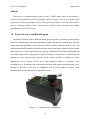
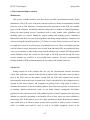
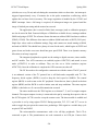
The project is a motion tracking system. It uses a CMOS image sensor to take images, a
Freescale microcontroller to process the images, and servo motors to aim a laser pointer at the
center of the widest moving object in view. The project also includes a real time clock which is
used to timestamp motion events. Users interact with the system through push buttons,
potentiometers, and an LCD screen.
1.0
Project Overview and Block Diagram
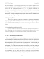
The Motion Tracking Camera Platform design project provides a system for capturing image
data from a CMOS image sensor and performing a simple, and therefore relatively time efficient,
image processing algorithm to detect and track motion real-time within the field of view. The
module automatically translates the motion location into a target point within the object bounds,
and provides servo control signals that cause properly calibrated motors to aim a pan/tilt platform
toward that target point. For the purpose of proof of concept, a laser pointer is activated atop the
platform to verify correct target locations, but the system provides a backbone for many
applications such as security devices, basic sight emulation robotics, or automatic video
recording devices. In addition to the autonomous operation of the motion tracking system, a user
interface is provided in the form of pushbuttons and an LCD module to display useful
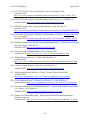
information such as the timestamps of significant events.
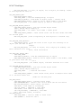
Figure 1.1 – Completed Project Photograph
-4-
ECE 477 Final Report
Spring 2006
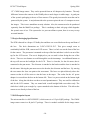
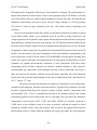
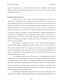
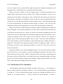
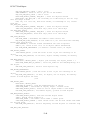
Figure 1.2 – Project Block Diagram
2.0
Team Success Criteria and Fulfillment
Project Specific Success Criteria:
•
•
•
•
•
An ability to analyze successive stored images for changes/movement in field-of-view.
An ability to calibrate laser-aiming platform relative to camera field-of-view.
An ability to aim laser at a torso 10 feet away.
An ability to timestamp and log motion events.
An ability to configure/control system operation and view event logs via
pushbuttons/LCD.
All five project specific success criteria were successfully demonstrated. The difference
algorithm is able to determine whether movement occurred. The calibration routine successfully
determines values to calculate where to aim. The find center algorithm successfully determines
the proper PWM duty cycle to point at a torso ten feet away. The real time clock runs
-5-
ECE 477 Final Report
Spring 2006
successfully and events are properly time stamped. Users are able to successfully interact with
the device using the pushbuttons, potentiometers, and LCD.
3.0
Constraint Analysis and Component Selection
3.1 Computation Requirements
The processor must be able to determine the location of a moving object and focus the laser
pointer on its center in real time. To do this, the processor first acquires a reference image to use
from the camera and stores it in the microcontroller’s memory. From then on, images are
captured at a fixed interval and sent to the microcontroller, which runs a simple difference filter
on the new image and the reference frame. If a difference is seen (meaning an object has come
into view that is not in the reference frame), the center of the detected object is determined, and
the microcontroller outputs PWM signals to two servo motors (used to control tilt and pan) that
point the laser at the moving object.
3.2 Interface Requirements
The microcontroller interfaces to the camera, the LCD, two push buttons, the on/off switch,
the laser pointer, and the two motors. The camera requires 20 pins of I/O in total, 16 for image
data and 4 for control signals. The LCD interface requires 11 pins of I/O, 3 for control signals, 8
for data values. The two push buttons each need one pin of I/O. The laser pointer needs one pin,
and each PWM output also needs one output pin. In total, the microcontroller will need 36 I/O
pins.
3.3 On-Chip Peripheral Requirements
There are a few on-chip peripheral requirements for the design. An I2C bus interface is
needed to set register values on the camera. The TIM system is needed to keep a real time clock
running, which is used to keep timestamps of motion events. Two timer channels are required to
generate the necessary PWM signals at 50 Hz each.
-6-
ECE 477 Final Report
Spring 2006
3.4 Off-Chip Peripheral Requirements
The off-chip peripherals required are an LCD interface, push buttons for scrolling through
the LCD interface, enabling/disabling the LCD backlight, an on/off switch, a laser pointer, and
two servo motors. The LCD interface is used to display the timestamp data. Three push buttons
are used: two push buttons for scrolling through the LCD interface, and one push button for
enabling the LCD backlight. A simple two position switch is used to turn the device on or off. A
standard red laser diode is used to project the laser beam on the moving object. The two servo
motors are used to tilt and pan the laser pointer.
3.5 Component Selection Rationale
The design has two major component choices. The first choice was to determine which
camera to use. Multiple cameras were examined and researched, and the decision was narrowed
down to either the Omnivision OV6120 [1] or the Kodak KAC-9630 [2]. Both cameras use the
I2C bus for setup. The Kodak camera has a resolution of 128 x 101 pixels, and the OV6120 has a
resolution of 352 x 292. Both cameras are monochrome. Both cameras also had a downside. The
Kodak KAC-9630 is meant for more high speed applications, able to capture 580 frames a
second, making it a very expensive ($270 plus $100 for a matching lens). The problem with the
OV6120 is that there are no American vendors for the part. Instead, we decided to go with the
OV6620, which differs from the OV6120 in only one aspect: the 6120 is monochrome, and the
6620 is color (in fact, they are so similar, they share a data sheet). The OV6620 is sold for
$43.65 along with a lens.
The second choice was microcontroller selection. The microcontroller needed to have all of
the required peripherals as well as plenty of memory and be fast enough to meet the real time
constraints. The newer 16-bit 9S12 and 9S12x series microcontrollers from Freescale have most
of the on-chip peripherals needed (the older microcontrollers did not have onboard I2C
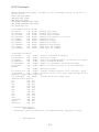
controllers) and run fast (25 MHz). Two microcontrollers were investigated, the MC9S12DP512
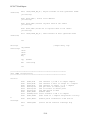
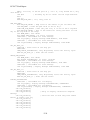
[3] and the MC9S12XDP512 [4]. Table 3.1 shows a comparison between the two devices.
-7-
ECE 477 Final Report
Spring 2006
Microcontroller
MC9S12XDP512
MC9S12DP512
Internal RAM
32,768 Bytes
12,288 Bytes
Flash Memory
524,288 Bytes
512,000 Bytes
Serial Interfaces
CAN, IIC, SCI, SPI
CAN, IIC, J1850, SCI, SPI
Timers
8
8
PWM Channels
8
8
PWM Bits
8
8
I/O Pins
91
91
Additional Peripherals
Periodic Interrupt Timer
Addressable External Memory
Table 3.1: Comparison between two Freescale microcontrollers
The MC9S12DP512 was chosen because the one reference image could fit in its memory
with enough room to spare for difference data and other variables. Also, it would cost a lot more
to be able to program the MC9S12XDP512 as the cheapest programming suite available cost
$600. Therefore the group chose to work with the MC9S12DP512.
4.0
Patent Liability Analysis
4.1 Results of Patent and Product Search
After searching the USPTO webpage [5] several patents were discovered that need to be
analyzed. The patents were found by searching issued patents on the USPTO webpage for the
phrase “motion tracking”. The search returned 525 patents, however most of them were not
relevant to the project. Most of the patents were rejected from analysis because they did not use
a camera to detect motion. Therefore the project can perform the same functionality but do so
in a substantially different way than the issued patent. There are five patents that need to be
analyzed because they are similar to the project and the patents are still in effect.
United States Patent 6,819,778 [6]
This patent is for a “Method and system for tracking a fast moving object”. This patent is
for a system that will move a camera to follow a moving object. It does this by storing two
-8-
ECE 477 Final Report
Spring 2006
video frames into two memories and comparing the two frames. If motion is detected the
camera zooms in on the object and tracks it until it is no longer visible. More advanced
calculations are preformed to determine how far the camera needs to pan to still track the object.
The patented device does not look for known shapes in the video frame it only detects motion.
United States Patent 5,243,418 [7]
This is a patent for “Display monitoring system for detecting and tracking an intruder in a
monitor area”. The patented product stores a background image in memory as a reference.
Differences are found between new images and the background image. They “binarize” the
differences by checking the difference to a stored threshold value. This is done to make the
patented product “resistant to environmental variations”.
4.2 Analysis of Patent Liability
The project has limited potential to literally infringe on the above patents. The process of
storing a reference frame and comparing it to a new frame is the only aspect that is literally the
same as some of the existing patents. However, this is not significant since so many patents
were issued that have the same frame comparison method of detecting motion. Also, the method
is never mentioned as a claim in any patent by itself. This comparison is also obvious to anyone
skilled in the art so it should not be patentable. The patents differed literally from the project
because when there was movement involved in the patent the image sensor was being moved.
There is a greater chance for the design to infringe on patents under the doctrine of equivalents.
The USPTO describes the Doctrine of Equivalents as a way of answering the question, "Does the
accused product or process contain elements identical or equivalent to each claimed element of
the patented invention?” [8] Since moving the image sensor and moving a laser are very similar
they could be argued to be equivalent. The movement is only specified as sending a control
signal to a motor. The motor could be connected to anything and be controlled the same way.
The project moves the laser by modifying the duty cycle of a PWM output. The PWM output is
connected to a servo motor that controls either the pan or tilt of the laser. Lastly, tracking motion
could be argued to be the most significant part of a device that moves the camera to follow
motion.
-9-
ECE 477 Final Report
Spring 2006
4.3 Action Recommended
The project group feels that there is not any infringement because by not moving the image
sensor the processing is much simpler. There is no correction for the different image that will be
received after moving the image sensor in the project. This simplicity represents a substantial
change in the implementation. Also, by not moving the camera the functionality of the project is
different from the patented devices. The project can not view a moving object for as long as the
patented devices because of its fixed field of view. There is still some potential for infringement
because the differences between the project and the patented products could be argued obvious to
someone trained in the art. The project group recommends only moving the laser to avoid
infringing on existing patents. If the camera were to move with the laser there would be much
more of a chance for literal infringement.
5.0
Reliability and Safety Analysis
To better understand the overall reliability of the entire design without an exhaustive analysis
of each individual component, a focused approach is used to examine a few of the critical
components which are most likely to fail. Chosen based on complexity and operating
temperature, four devices are selected for this analysis and their failure rates will be quantified
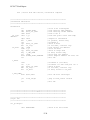
by procedures developed by the United States Department of Defense and detailed in the MILHDBK-217F [9]. The selected components are summarized in Table 5.1 below.
Part Number
Description
Part Failure Rate (λp)
MTTF
MC9S12DP512
Microcontroller, 16-bit, 112
5.376 Failures/
186011.9048 Hours
pin SMT
106 Hours
(21.234 years)
Step Down DC-DC Converter,
5.868 Failures/
170415.8146 Hours
8 pin DIP
106 Hours
(19.454 years)
CMOS Image Sensor, 16-bit,
4.671 Failures/
214086.9193 Hours
48 pin SMT
106 Hours
(24.439 years)
24 Character LCD Display
2.92 Failures/
342465.7534 Hours
Controller, 8-bit, 80 pin SMT
106 Hours
(39.094 years)
LTC1174-5
OV6620
PC 1202-A
Table 5.1 – Selected Reliability Analysis Components
-10-
ECE 477 Final Report
Spring 2006
Each of the parts listed in Table 5.1 fall under the Microcircuits category (section 5.0) of the
military handbook. The following sections in the document outline the values and associated
assumptions used to compute the failure rate for the given device using the following formula:
λp = (C1*πT + C2*πE)*πQ*πL Failures/106 Hours
where:
λp
is the part failure rate,
C1
is the die complexity failure rate,
πT
is the temperature factor,
C2
is the package failure rate,
πE
is the environmental factor,
πQ
is the quality factor, and
πL
is the learning factor.
Mean time to failure (MTTF) is then calculated as the inverse of the failure rate, or 106 / λp.
Calculation specifics, including parameters and justifications, for each component analyzed are
included in Appendix G.
The microcontroller [10] is an obvious weak point of the design due to its complexity and
importance to the circuit. As one of the components that is setting the upper bound on the
lifecycle of the system, it is being considered for the reliability analysis. Most of the parameters
are clearly defined by the given information about the chip including junction temperature, pin
count, package type, and production phase. The only assumption made with the MC9S12DP512
is that it falls into the non-hermetic packaging category, which produces a higher approximation
for failure than the other options. It is also worth noting that the maximum junction temperature,
Tj, is used in the analysis to provide the ‘worst-case’ failure rate, which is the case for all
components considered. As seen in the resulting failure rate values, the microcontroller poses a
moderately significant threat to the reliability of the system, even more so considering that a
failure with the microcontroller will result in complete loss of system functionality. In the event
of such a failure, the entire device would likely have to be replaced.
The linear regulator [11] is arguably the most critical component on the board as it provides
power to all components and has the highest failure rate of any device in the design. A critical
-11-
ECE 477 Final Report
Spring 2006
assumption was made with the LTC1174-5, that it contains 1 to 100 transistors, an
approximation made based on the function block diagram provided in the datasheet. Similar to
the microcontroller, it is also assumed non-hermetic and a worst-case approximation is made
with the junction temperature. The results show that the linear regulator is slightly less reliable
than the microcontroller, but enough so that it is the most likely component to fail. A typical
failure would likely cause the device to have to be replaced, however the DIP package makes it
easier to diagnose and repair if possible.
A significant subsystem involved in the motion tracking project is the camera module [12].
Instead of analyzing the entire module, just the image sensor chip is considered. The sensor is
assumed to be similar to a 16-bit microcontroller with a conservative assumption of junction
temperature, matching the specifications for the microcontroller itself. This analysis is closely
related to the microcontroller, with the exception of the number of pins, so the reliability issues
are similar. Different from the microcontroller, however, is that a failure of the image sensor can
be fixed by simply replacing the camera module PCB. This result of having a modular design is
an attractive feature of the system in the case of device failure.
The LCD panel and associate driver circuit [13] is not necessarily a ‘mission critical’
subsystem, but is deserving of reliability analysis due to the similarity to other devices
considered. The segment driver, a Samsung S6A0069X, is essentially an 8-bit microcontroller
and the junction temperature assumption is made similar to the camera module. Since this
controller is relatively simple compared to the rest of the components analyzed it has the lowest
failure rate, with an MTTF just short of 40 years. As with the image sensor, the modular design
allows an LCD failure to be corrected by replacing the inexpensive LCD module.
A simple analysis of the four major components provides good insight into the reliability of
the entire system. Under assumptions that over exaggerate actual operating conditions, the results
summarized in Table 5.1 indicate an approximate failure rate for the entire system. The most
critical component in terms of shortest failure rate is the linear regulator, which is unfortunate
due to the difficulty of repair, but expected nonetheless. Close behind is the microcontroller,
which is also a difficult component to service. The gaps between failure rates continuously
increase with the image sensor being next, followed by the LCD controller. These values are
acceptable due to the general ease of replacement, and in reality are even lower when actual
junction temperatures and loading conditions are taken into account.
-12-
ECE 477 Final Report
Spring 2006
In order to facilitate the failure mode, effects, and criticality analysis (FMECA), the
schematic is divided into several blocks by function. This breakdown is summarized in Table
G.1, included in Appendix G. Two criticality levels are appropriate for the design, referred to as
‘high’ and ‘low.’ A high criticality is defined as any failure in which physical injury is a possible
result. This includes, but is not limited to, the possibility of fire, explosions, or excessive heating.
A low criticality is defined as any failure that does not have the potential to cause physical harm,
but one which would render at least part of the system unusable and cause customer
dissatisfaction. In a final system design, failure probabilities would be set to λ < 10-9 for a high
criticality level, and λ < 10-5 for a low criticality level, standard accepted industry values. It is
important to note that the motion tracking camera system can be potentially more harmful if it is
specified for use in a security setting. Although this use is not recommended under the current
design, the criticality level is defined as “low/high” for these cases. The completed FEMCA table
is found in Appendix G [14].
6.0
Ethical and Environmental Impact Analysis
6.1 Ethical Impact Analysis
When considering the ethical impact of this project, there are many things that need to be
taken into consideration involving the application of the system. Depending upon the application,
there could be potential for harm to users or to non-users who happen to be nearby. If this project
is used in a toy robot, the concern of the laser pointer comes into play. How dangerous is it to
have a laser pointer shine into someone’s eye? The risk of damage from a laser pointer has to be
reduced by placing a piece of filtered glass in front of it. This reduces the power of the laser
pointer significantly and makes it safe for everyday use as long as the eye is not exposed to it
over extended periods of time. A warning label placed on the product would be beneficial to
inform the user of the possible hazards of extended exposure to lasers.
Another concern involved with this project is the inability to differentiate targets. Since the
camera is black and white and fairly low resolution, it would be nearly impossible to create an
algorithm for target differentiation unless the only difference was the color being black or white.
If this project is used as a sentry turret type of system, there is nothing stopping it from shooting
-13-
ECE 477 Final Report
Spring 2006
or aiming at friendly targets since it has no way of telling the difference between hostile and
enemy targets. This could potentially cause harm to the user or nearby people who are unaware
of the system. This must be very well explained in the user documentation as well as include a
warning label near the power on button to inform the user of the potential hazards. Also, to allow
for the safe passage of friendly targets through the area covered by the system, a “laser off”
switch has been implemented. This allows the user to disable the laser pointer at the flip of a
switch to allow motion to pass by without any harmful results to the moving object.
As with any electronic devices there is always the possibility of fire or electric shock to the
user if the device is handled incorrectly or if a malfunction occurs, especially with devices
containing batteries, as batteries can explode when exposed to fire. Warning labels should be
placed on the package informing the user of such possible harm and the user manual should also
warn of these dangers. Extra sealant is used on the PCB to make sure there are no exposed
connections. The packaging completely encloses the system, so there should be no access to the
PCB or any components, therefore making it very difficult to touch anything carrying current
and reducing the risk of shock. The battery pack will need to be accessible, so the battery casing
contains the highest risk of shock within the system unless it is used incorrectly or disassembled.
The power on/off switch is included to allow the user to shut off power at any time.
Another ethical consideration is to make sure you are not selling a product that is expected
to fail or malfunction. Extremely thorough testing must be conducted before approving this
project for manufacture, sale, or use. Especially with the potential harmful effects to the user and
nearby people if a malfunction occurs, there needs to be virtually no possibility of malfunction
before releasing this product. If it is used in a toy robot, a malfunction could cause extended
exposure to a laser pointer causing damage to the eyes or possibly even blindness. If it is used in
a sentry turret system, it could inadvertently injure friendly targets or fail to correctly aim at
hostile targets, thus allowing them to pass through the detected area without any negative effects.
If it is used in a security system, it could fail to track a target and could lead to hostile targets
breaking into a secure compound.
-14-
ECE 477 Final Report
Spring 2006
6.2 Environmental Impact Analysis
Manufacture
This project contains multiple parts that project possible environmental hazards during
manufacture. The PCB is one of the main concerns as there are many environmentally harmful
processes used in PCB fabrication. Cleaning and surface preparation of the PCB uses multiple
types of acids, halogens, and alkaline solutions and produces a number of harmful byproducts.
During the metal plating process, byproducts such as acids, stannic oxide, palladium, and
chelating agents are created. During the pattern printing and masking process, chlorinated
hydrocarbons and alkali are some of the byproducts and during etching ammonia, chromium, and
acids are among the harmful byproducts. [15] There are various leftover metals as well that are
too small to be reused or recycled so they are generally thrown out. There are multiple steps that
could be taken to reduce the harmful waste created from fabricated PCBs, but realistically there
is no way to eliminate it. Some of these steps include making a more compact PCB design which
would ultimately reduce the overall size and weight of the PCB, therefore having less waste
created. Another way would be to use possibly more expensive, but more environmentally
friendly methods of PCB manufacturing that do not contain such harmful chemicals.
Normal Use
During normal use of this product, there are very few environmental concerns associated
with it. One of the main concerns is the fact that it contains lead. Lead solder is used to connect
parts to the PCB, many of the headers contain lead, the PCB itself contains lead, and the
microcontroller used in this project contains lead. Lead is considered to be fairly dangerous to be
exposed to and many countries and companies are putting forth a large effort to reduce or
eliminate the existence of lead in available products. Even short term exposure to lead can lead
to vomiting, diarrhea, convulsions, coma, or even death. Anemia, constipation, and kidney
problems are also concerns involved with extended exposure to lead. Pregnant women and young
children are especially susceptible to the harmful effects of lead, which can cause stillbirths or
miscarriages [16]. If this product were to be widely manufactured, more advanced precautionary
steps would need to be taken to ensure as little lead as possible is used to create it. Lead-free
solder is available and could be used, as well as an RoHS compliant version of the
-15-
ECE 477 Final Report
Spring 2006
microcontroller, although it is more expensive. Some RoHS compliant headers are available,
although in some cases headers were used only for convenience and may not even be necessary
in a finished product.
Another possible health concern during normal use is possible exposure to mercury. Almost
all products in the United States have made their best effort to rid themselves of mercury due to
the dangerous side effects of exposure, but some parts may still contain trace amounts. Harmful
effects of mercury exposure can include damage to the nervous, digestive, and respiratory
systems [17]. Many batteries used to contain mercury, but most companies, like Duracell, have
removed all traces of mercury from their batteries and manufacturing processes [18].
Disposal and Recycling
Disposal of many electronic products is considered dangerous or harmful to the environment
and this product is no exception. It contains many hazardous substances and should not be
disposed of in the normal ways. Although it is not extremely beneficial or profitable to recycle
printed circuit boards, the extracted materials and boards can be reused and save some money as
well as protect the environment. The user documentation should include information notifying
the user that the product should not be disposed of in a normal way, but it is difficult to convince
people not to do so. PCB manufacturing companies need to provide easy ways to recycle for
users and the product documentation should include methods of recycling or contact information
regarding recycling.
The batteries used in this project could also pose an environmental hazard depending upon
what kind of batteries the user decides to use. Most alkaline batteries are safe to be disposed of
normally, but you should refer to the battery manufacturer to be sure before disposing of them.
Battery manufacturers such as Duracell [18] have made an extra effort to make their batteries
environmentally safe. Most rechargeable batteries are not considered to be environmentally safe
and you should contact the battery manufacturer for details on how to correctly dispose of such
batteries. Alkaline batteries are recommended for this product, so the disposal of batteries should
not be a problematic issue.
-16-
ECE 477 Final Report
7.0
Spring 2006
Packaging Design Considerations
7.l Commercial Product Packaging
The two products selected for analysis are the Creative WebCam Live! Motion and the x10
MultiView. These two products share features in common with the project without directly
implementing it.
Creative WebCam Live! Motion
First, the Creative WebCam Live! Motion [24] is a webcam that has the ability to pan, tilt
and zoom in order to automatically follow a moving body. If there are multiple moving bodies it
will zoom out to try and keep both bodies in the video feed. The camera is capable of moving
200 degrees horizontal and 105 degrees vertical. It has a USB 2.0 interface to a PC that allows it
to capture 30 frames per second of 640x480 resolution video. The camera also has a shutter
button on the top that will trigger it to take a picture. The camera has a stand with a fold out leg
that can either sit on any flat surface, such as a CRT monitor or the leg can be folded down to
straddle a LCD monitor. A very nice feature of the camera is its very wide viewing range is
accomplished with a very small motor mount at the base of the camera. A major downside to the
packaging is the inclusion of a USB interface. The length of the cable determines what can be
captured by the camera, whereas if the camera were wireless then much more could be captured.
There is not much the project is able to copy or adapt from this product. The project's camera is
going to be stationary and only the laser pointer is going to move. Comparing the two designs is
difficult because the designs were created with different goals.
x10 MultiView
The x10 MultiView [25] is a system of PC peripherals and software that allow up to four video
cameras to interface to a computer. A picture of the total system from the x10 webpage is listed
as Figure 2. The computer program can simultaneously monitor live video feeds from all four
cameras. The system also features a mode very similar to the project where the camera will go
into a sleep like state until it detects motion. Once the camera is alerted it begins saving pictures
to the PC and recording a timestamps on each picture. The cameras the system interfaces to are
either wireless XCam2 or WideEye cameras. Both cameras are wireless video cameras with a
-17-
ECE 477 Final Report
Spring 2006
1/3” CMOS image sensor. They can be powered from an AC adapter or by batteries. The only
difference between the cameras is the WideEye has a much larger viewable range. A good part
of the system's packaging is the use of four cameras. This greatly increases the area that can be
protected by the system. A major downside to the system requires the use of a computer to store
the images. This is not a standalone security solution. Also, the cameras need to be purchased
separately from the MultiView package. This is confusing on their web page which degrades
the system's ease of use. This system also is a pure surveillance system, there is no way to stop
an actual intruder.
7.2 Project Packaging Specifications
The PCB is housed in a Serpac-153 hobby box and there are several holes on the top and front of
the box.
The box's dimensions are 5.630”x3.250”x2.510”. This gives enough room to
comfortably hold the PCB, camera and LCD screen. There is a hole cut out the front of the box
for the camera. The pan motor is mounted to the top of the box and there is a hole cut out of the
top for the LCD screen. The text is displayed so you can read it when facing the rear of the
device. There are two buttons to scroll through the saved timestamps. An additional button on
the top will turn on the backlight for the LCD. There is a bracket, for the tilt motor, that is
connected to the pan motor. The tilt motor is attached to the bracket and the laser is attached to
the tilt motor. Moving the pan motor moves the bracket, the tilt motor and the laser. By moving
the two motors the laser can point at the movement. The laser was placed directly above the
camera so that it will be easier to aim the laser at the target. The socket for the AC power
adapter is recessed into the box on the bottom left. There is a power switch on the bottom right
of the box. Along the side there are three recessed potentiometers. They are used for calibration
and for the LCD contrast. They are turned with a small straight blade screwdriver only. The
whole box is held up at an angle by a spacer attached to the bottom of the box. This allows the
camera to see directly in front of the box.
7.3 PCB Footprint Layout
The microcontroller is a MC9S12DP512, which comes in a 112 pin LQFP package. The CMOS
image sensor comes in a 48 pin LCC package. There is a module available for the image sensor
-18-
ECE 477 Final Report
Spring 2006
that outputs to a 32 pin header placed on the PCB. The project uses the module because of the
ability to rapidly prototype with the camera. The PCB is 2.5” wide and 3.3” long.
8.0
Schematic Design Considerations
8.1 Microcontroller
The microcontroller that will be used in this project is the MC9S12DP512 [4]. It is in a
112-pin LQFP package. 112 pins may be more than necessary, but a large amount of pins are
needed to connect to all of the peripherals and off chip components. The camera module [26]
that will be used in the project requires a 32 pin header, 25 of which will go to the
microcontroller. Most of these will require generic I/O ports, but most notably two of them are
reserved for I2C data and clock signals. The pixel clock, vertical sync, and horizontal reference
signals will be wired to interrupt pins so that the chip will know exactly when to read in each
pixel as it is sent. Pixel data and configuration settings can be sent to the microcontroller from
any I/O pin. The LCD module [27] chosen for this project has a 16 pin header, 12 of which go to
the microcontroller. All 12 of these pins can be generic I/O, but for simplicity the 8 data pins will
be routed to an eight bit data register that is mapped directly to eight data pins. The two motors
[28] that pan and tilt the laser pointer platform both require a PWM input from the
microcontroller. Unfortunately, the servo motors require a 50 Hz pulse wave and the PWM
channels can not go that slow when the chip is clocked at 25 MHz. A custom PWM wave has to
be created using the ECT/TIM channels. ECT channel 7 controls the frequency of the pulses on
the other channels. Channel 3 and 5 are used for the two pulses going to the two servo motors
and each channel controls the duration of the pulse. These channels are controlled by a 16 bit
value representing pulse duration. The laser pointer will also require a signal from one of the
microcontroller’s output pins to tell it when to turn on/off. Two potentiometers will be used for
calibration of the motors and will each use an ATD converter. Two buttons will be used for
scrolling between the events list (and also used at start up to set the clock) and each require an
input pin. A spare eight pin header will be connected to one of the registers that are mapped to
pins for easy data output in case the project requires an expansion of microcontroller outputs or
inputs. The programming header will need connections to the BKGD pin and the RESET pin.
The microcontroller will also need a PLL filter and a clock signal from a resonator. These
require specific pin assignments that occupy nearly half of the lower side of the microcontroller.
-19-
ECE 477 Final Report
Spring 2006
For the microcontroller itself, the model was chosen due to meeting all of the above
necessities as well as having a large amount of RAM. The I2C capabilities, PWM channels, and
ability to map pins to the interrupt vector were the largest constraints, as well as being able to run
fast enough to read in pixel data from the camera and manipulate it accordingly with time to
spare. The PLL circuit was documented in the data sheet and recommended three capacitors of
values 4.7nF, 470pF, and 100nF as well as a 100k ohm resistor. Bypass capacitor values were
suggested between 100 and 220 nF for the power supplies to the microcontroller.
When the microcontroller reads in pixel data from the camera, it runs it through an
algorithm to find difference data between the current frame and a reference frame. After a full
frame has been captured, it runs that frame through a special routine to find objects within the
difference data, which essentially represent motion in the field of view of the camera. It will then
calculate values to output to the ECT registers that control where the servo motors aim based on
where the motion was detected within the image.
8.2 Clock Oscillator/Resonator
The 25MHz ceramic resonator [29] chosen for this microcontroller is called the AWSCR,
from Abracon. It comes as a three pin device with a crystal connected to two internal capacitors
that lead to one pin labeled ground. The other two pins are for input and output to the crystal,
output being the 25MHz clock signal being used by the microcontroller. The manufacturer
recommends tying the input and output together through a 1M ohm resistor and 25MHz is the
manufacturer’s maximum recommended clocking speed for this specific microcontroller.
8.3 Camera Module
The camera module, the C3088 [26] which utilizes an Omni Vision 6620 color camera
chip, will be connected to a 32 pin header on the PCB that is setup as 16 pins by 2 pins. 25 of
these 32 pins will be connected to the microcontroller; of the other seven, four will be connected
to ground and two to five volt power. The last pin is for analog video output and will mainly be
used for testing; however a wire will be run to the outside of the box so that it is accessible to
watch the video feed. Of the 25 pins going to the microcontroller, 16 are reserved for data, one
for reset, one for power down mode, two for I2C, one for odd field flag, one for horizontal
reference output, one for vertical sync output, one for pixel clock output, and one for optional
-20-
ECE 477 Final Report
Spring 2006
external clock input. This project will not make use of the odd field flag or the external clock
input. The 16 pins for data allow the transfer of two bytes at a time, even though each pixel takes
four bytes to represent. The Y (luminance) byte will be the only one used in this project, so eight
of the 16 data pins will not be used unless the camera is operating in black and white mode. The
VSYNC, HREF, and PCLK signals are extremely important for telling the microcontroller when
images, rows, and individual pixels are being sent, which is why they have all been mapped to
interrupt pins. The camera module itself already contains its own internal pull up resistors,
oscillator for the clock signal, and bypass capacitors.
8.4 LCD Display Module
The LCD module, the PC-1202-A [27], will connect to the PCB through a 16 pin header
(two rows of 8 pins). Eleven of these pins will be wired directly to the microcontroller, two of
them will be ground, and one of them will be power. The last two pins will be connected to other
components. One will go to a potentiometer output that will control the LCD contrast adjust pin
and the other pin will be connected to a push button that will connect to power when pressed and
connect to ground when depressed. This signal will control the LCD backlighting so that it will
be easier to see, if necessary, but not use up power when unnecessary. Of the eleven pins
connected to the microcontroller, eight of these pins are for data so that one byte can be sent at a
time. One pin will be for selecting read or write, one pin for enabling the device, and one pin for
register select when reading data from the LCD. This project will not be reading from the LCD
module, so the register select will not be used and the read/write pin will always be set to write.
The LCD is used mainly for communicating with the user in setup and calibration, but can also
be used to view timestamps of motion events any time during normal operation.
8.5 Motors
The motors, GWS NARO STDs [28], will each have a small three pin header connected
to the PCB. One of the pins will be for ground, one for five volt power, and one for the PWM
output from the microcontroller. This PWM output will be the control signal that determines the
position of the motor based on the duty cycle. The motors will be physically attached to
platforms that move the laser pointer, although the motors will have no electrical connection to
the laser pointer.
-21-
ECE 477 Final Report
Spring 2006
8.6 Laser Pointer and Laser On/Off Switch
Two of the pins coming out of the Button/Laser header will go towards the laser pointer.
One is a ground signal and one is the output from the microcontroller that will turn on when
movement is detected and it is attempting to point at a target. There will be a SPST switch
between the header and the laser pointer that will allow a user to manually disable the laser
pointer if desired.
8.7 Up/Down Push Buttons
The two push buttons used for scrolling through the event cycle and for setting the clock
will each be attached to a two pin header, which is attached to ground and the microcontroller.
The pins on the microcontroller that it attaches to will be ones that are able to be used as active
low interrupt pins so that the microcontroller does not need to constantly poll the pushbuttons, it
will just be sent an interrupt when they are pressed. Pressing a button will pass the ground signal
to the microcontroller input which will be viewed as a short and when depressed they will leave
the microcontroller input as an open circuit.
8.8 Calibration Potentiometers
There will be two 10k potentiometers [30] directly on the bottom of the PCB. They will
be accessible, although not easily, so that they can be changed to calibrate the motor alignment,
but not accidentally moved around to mess it up. They will each be attached to power and ground
as well as a microcontroller input to an ATD converter. The value put out by the potentiometer
will be used in the motor aiming algorithms to calibrate, align, and correctly aim the laser pointer
at the target.
8.9 Power Circuit
The power circuit connects the battery power and power from a wall wart through two
Shottky Diodes [31] to ensure current flowing in the right direction. The battery power will come
from a pack of 4 AA batteries. Immediately after the diodes, there will be a SPST switch that
controls whether or not power will actually be connected to the board or not. Following the
switch will be a MIC29150 power regulator [32] to ensure that no more than five volts reaches
-22-
ECE 477 Final Report
Spring 2006
the circuit components. A bypass capacitor connects the real five volt power coming out of the
regulator to ground. In order for the MIC29150 to output five volts, the input voltage must be at
least six volts from the data sheet formula of (Vout < Vin -1). Therefore, rechargeable AA
batteries can not be used (unless five batteries are used instead of four) due to the lower voltage
of 1.2V. Regular alkaline 1.5V AA batteries will be used. Much of the component selection was
based on a five volt power requirement in order to greatly simplify the power circuit and power
constraints by only needing one voltage source level.
8.10 Programming Header
The 9S12 series chips have a simple way of connecting to a background debug module
[33], using only the BKGD and RESET pins from the microcontroller and power and ground
signals. Both the BKGD and RESET pins need to be connected to power through a 10k ohm
resistor.
8.11 Expansion Headers and Expansion PLD
Incase it is needed in the future, an expansion PLD port will be placed on the board in a
20 pin DIP package with each side attached to a ten pin header for easy access. It will not be
connected to anything else on the board and must be manually wired when/if it is needed.
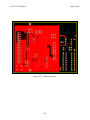
9.0
PCB Layout Design Considerations
When viewing the PCB layout as a top down design process, many general considerations
are presented, including standard good design practices and project specific issues. These general
points can be broken into physical considerations and electrical considerations, and further into
hard constraints which must be followed and soft constraints which are preferred, but not
required. The major physical hard constraints for this design are component sizes. The
microcontroller is a 112-pin, 22 mm2 LQFP package [34] which allow a 12 mil trace width to the
pins. Headers for all external connections have pins spaced at .1” and are arranged as 2x17 for
the camera module, 2x8 for the LCD, 1x3 for all potentiometers and servo connections, 1x6 total
for the pushbuttons and laser enable, and several 1x2 headers for the various remaining
connections. In total, these headers make up a large percentage of the component area on the
-23-
ECE 477 Final Report
Spring 2006
PCB and must be arranged for efficient use of space and ease of routing. The camera header is a
unique hard constraint in that it must be close to the appropriate edge of the board to avoid the
use of long ribbon connector, which would be hazardous to critical clock data. The final physical
dimension worth noting is the power circuit, since the voltage regulator is a TO-220 package
[32] which is relatively large compared to the type 1206 surface mount components used
elsewhere.
Physical soft constraints include the location of components on the board, with the exception
of the camera header which is now considered fixed. In an effort to reduce interference, the
voltage regulation circuit should be kept separate from the digital sections and close to the power
input and battery location in the back of the package. The LCD header should be placed near the
location of the LCD panel, which is the next component inward from the power circuit. With this
arrangement, it makes logical sense to position the microcontroller between the camera and LCD
headers, near the center of the board. Orientation of the microcontroller is determined by the
most critical traces on the PCB, the camera’s PCLK and HREF clocking signals. Wanting these
signals to be input to interrupts, and considering the I/O requirements (detailed below) for each
peripheral, the optimal microcontroller orientation is easily determined. With these major
components placed, all other connectors are placed to minimize distance to their respective
microcontroller pin connections. With intelligent selection of these connections, this leaves a
large area open for the sensitive oscillator circuit and bypass capacitors. The final component
layout shows the successful implementation of the above considerations with a final board size
of 2.5” wide by 3.3” long.
The general electrical considerations are made up of manufacture circuit requirements,
considered hard constraints, and noise reduction practices, considered soft constraints. Freescale
provides a suggested PCB layout for all power, ground, oscillator, and PLL connections to the
microcontroller [10]. A list of considerations provided in the datasheet specify that ceramic
decoupling capacitors be placed physically close to each supply pair, low ohmic low inductance
connections be used between VSS1, VSS2, and VSSR, VSSPLL be direction connected to
VSSR, traces in the oscillator circuit be as short as possible, and that no signals be routed
beneath the oscillator circuit. These specifications were covered by the suggested PCB layout in
the document, which is closely followed including the copper pour under the microcontroller.
-24-
ECE 477 Final Report
Spring 2006
This solid layout for powering the microcontroller will go a long way toward ensuring proper
operation free of avoidable noise sources.
The final set of hard general electrical constraints come from the PCB manufacturer
[35] and define minimum trace, spacing, and via sizes. The board thickness must fall between
.020” and .125”, traces greater than .0049”, spacing greater than .0045”, and finished hole size
greater than .010”. With these restrictions in mind, signal traces are routed with at least .012”
width and finished holes are no less than .015” wide, to be at least the signal trace width with an
additional tolerance to remain well above the manufacturer’s minimum.
The remaining electrical considerations are simply good design practices and regarded
as soft, yet very important, constraints to suppress and reduce the reception of noise. The
Motorolla Application Note AN1259 [36] is used as the main source of considerations, of which
the following were applied:
-
Connectors to external peripherals are placed physically close to their location
-
Clock signal traces are as short as possible and have nothing under them
-
45-degree angles are used for all turns, and no acute angles exist
-
The power circuit is physically far from the remaining circuit
-
Power and ground loops are avoided and wider traces are used (40+ mil)
-
Crossing signals are routed perpendicular to each other
-
Pixel clock signals are routed keeping distance from other signal lines
-
Ceramic capacitors are located next to each supply pair for each IC
A power grid consisting of 60mil traces around the outer perimeter of the circuit is incorporated,
and 40mil traces are used to bring power signals toward the center of the board. Since the bottom
of the PCB is lightly populated, a ground plane is created by the use of a copper pour covering
much of the circuit area. This plane is connected to the copper pour beneath the microcontroller
by a via near the center, and care is taken to prevent any loops on the power and ground lines.
These major noise reduction considerations are the applicable soft constraint suggestions, and all
are successfully implemented.
Beyond the general layout issues are specific considerations for each major component
of the system, and are considered from a bottom up design process. These points define the link
between the PCB design and the schematic design, and as such they closely parallel the
information presented in the schematic considerations. Beginning with the microcontroller, the
-25-
ECE 477 Final Report
Spring 2006
most important requirement, next to the suggested circuit provided by the manufacturer
mentioned above, is simply making logical pin assignments. With the microcontroller orientation
already determined, data is able to be routed to convenient pins while keeping the [Y7:Y0] and
[U7:U0] pixel data busses and the [DB7:DB0] LCD data bus routed in order to nearby full
register ports. This scheme allows data to be easily manipulated on these bus lines by addressing
their respective registers, and also provides close, non-overlapping traces directly to the headers.
Port pin assignments are determined in this fashion, which allows a majority of data traces to be
routed on the top side of the board. Pin assignments requiring specific functions (PWM, ADC,
I2C) determine the location of the associated header requiring these connections, but these are
still conveniently routed despite the additional constraint. The exception to this, unfortunately, is
the two I2C signals which must be routed relatively far from the microcontroller. These signals
end up crossing the camera data bus at non-perpendicular angles, but since the I2C
communication is mainly used for initialization of camera registers at startup, this activity is
mutually exclusive with pixel data and is therefore not a large concern. After careful planning,
and a bit of luck, the oscillator and PLL circuits fall comfortably on the remaining side of the
microcontroller not yet claimed by headers or I/O traces. This allows the manufacture’s
suggested layout to be followed closely and eliminates the need for any routing under this
section, helping to keep the noise issues down. The final microcontroller consideration was
providing access to the background debug pin, as well as the remaining programming pins,
which all are routed out to a programming header.
The next largest, and arguably most critical, component is the OV6620 camera module
[26]. As mentioned above, the PCLK, HREF, and VSYNC critical timing signals are routed
between ground traces to the microcontroller and are kept as short as possible. Bypass capacitors
used for the camera IC are already included on the module, so no additional power
considerations are required in the layout. With regards to pixel information, although only the Y
data is used, both Y and UV data busses are routed to the microcontroller going to ports PT and
PB in order to provide easier data manipulation in code. UV data is ignored, but is accessible if
eventually needed. As mentioned above, the I2C lines must be routed to the appropriate port pins
located on a different side of the microcontroller, but can be freely routed on the nearly vacant
underside. All other control signals are routed to general I/O port pins based on minimizing the
distance of each trace.
-26-
ECE 477 Final Report
Spring 2006
The third significant component requiring numerous signal lines is the LCD module
and associated electronics [27]. Placed on the opposite side of the microcontroller as the camera
module, the LCD header is near plenty of port pins for both the parallel data bus and the various
control signals. Once again, the bypass capacitors are included on the LCD module and therefore
are not considered. The contrast potentiometer and backlight pushbutton header used with the
display are mounted close to the header, keeping the entire LCD circuit to a confined and
convenient area.
The remaining components and connectors are placed to keep traces short, with a few
additional considerations. The power circuit includes a voltage regulator in a large package
which requires the board length to be stretched to accommodate the entire circuit. This works out
well for isolating the power system from the remaining components and the created board space
allows for the placement of a 20-pin expansion DIP socket and headers. The set of trimmer
potentiometers are mounted on the underside of the board such that they will be accessible from
the bottom of the package. Although this is seemingly an inconvenient location, it is actually
desired for this system since the potentiometers are used rarely and only for calibration. The
servo headers are located near their PWM control signal ports, while the pushbutton header is
placed near the most accessible of the remaining I/O outputs. With each component location
optimized for short signal routing, and with the proper port pin selection for natural flow, a very
compact and straightforward PCB is created.
10.0 Software Design Considerations
10. 1 Software Design
The most significant consideration in the project’s software design is that the image
acquisition and processing must take priority over all other functions. This is accomplished by
setting the VSYNC interrupt as the highest priority interrupt, and the HREF interrupt as the
second highest priority interrupt. When images are processing, no interruptions are allowed until
processing has completed. By examining the flowcharts in Appendix A, it can be seen that the
only task of the main loop is to poll the push buttons. PWM generation requires no interrupts or
updating until the duty cycle needs to change, which is handled by the image processing
interrupts. The real time clock is updated by counting pulses that occur on timer channel 7
-27-
ECE 477 Final Report
Spring 2006
(which occur every 20 ms) and calculating the current time relative to that value. An interrupt is
triggered approximately every 43 minutes due to the pulse accumulator overflowing, which
updates the real time clock in memory. The image acquisition is handled by the VSYNC and
HREF interrupts. Once a full image is acquired, all subsequent images are ignored until the
image is finished processing and the motors have moved.
The application code is stored in flash. Static messages (such as calibration prompts)
are also be stored in flash. Fourteen kilobytes of SRAM are available for use, starting at address
$0800 and going to $3FFF. The reference frame data starts at address $0B54 and runs to address
$3D6F (12.5kB). The difference data starts at address $0800 and ends at $095F (249 bytes).
Single byte values such as calibration settings, flags, and counters are stored starting at $0960,
and ends at $0B3B. This should leave plenty of room for the stack, which begins at $3FFE and
grows down, and in the worst case should not grow past $3F9E. There is no dynamic memory
allocation so no heap is required.
The integrated peripherals required are the analog to digital converter, timer module,
and IIC module. Two ATD converters are enabled (register ATDCTL2) and turned to scan
mode (ATDCTL5) in order to calibrate. They are also set to 10-bit resolution (register
ATDCTL4). Once the calibration is complete the ATD converters are shut off.
The IIC bus needs to be configured to communicate with the camera. The IIC protocol
is an enhanced version of the I2C protocol but is still backwards compatible with I2C. The
frequency divide register (IBFD) is used to drop the clock speed to 100KHz. The control
register (IBCR) is used to turn on the IIC peripheral. From then on, data is placed in the data
register (IBDR) and the IBCR is used to initiate start and stop conditions. The status register
(IBSR) is checked to see if a successful transmission occurred.
The timer module uses the TIOS register to set channel 7, 5, and 3 as output compare
channels. The output compare circuitry is connected to the pin by asserting the respective bits in
the OC7M register. OC7D is used to set up the counter resets. The timer module is enabled and
a pre-scalar is set by using register TSCR2. During operation, TC3, TC5, and TC7 are set in
order to toggle the port pin at the correct time, producing a 50Hz signal at a variable duty cycle
on pins OCM3 and OCM5.
The microcontroller communicates with a few off-chip peripherals. The LCD is
connected to port A. The potentiometers are each connected to an ATD pin. Camera clock
-28-
ECE 477 Final Report
Spring 2006
signals are connected to port J (PCLK and VSYNC) and port H (HREF), which supports
interrupt triggering. The camera luminance data is received on port P. Push buttons come into
general purpose I/O pins.
10.2 Software Design Narrative
For this project the code is broken into the following modules: real time clock,
calibration, I2C communication/camera initialization, push button detection, LCD functions, and
image capture and processing. The camera module used in the project accepts registers settings
through I2C commands. The camera initialization is performed by sending the camera’s slave
address out on the serial bus (0xC0), followed by pairs of 8-bit values. The first of the pair
represents the register value on the camera to set and the second of the pair represents the value
to write to the register. Upon startup, five camera settings must be adjusted: adjusting the speed
of the camera to a 850KHz pixel clock rate, setting the resolution to QCIF (176x146 pixels), and
adjusting the pixel clock so that it only runs while image data is being sent instead of being free
running, and changing the percentage of lightness and darkness in each picture to ensure each
frame taken has enough light.
PWM signals are generated by the timer module. PWM generation requires no
interrupts. PWM signals are generated by connecting output compare circuitry to timer pins.
Timer counters run up to a certain value, toggle the port pin at that value, reset, and begin to run
up again. By adjusting the counter limits and the timer pre-scalar, PWM signal frequencies and
duty cycles change. The timer is configured to generate a 50Hz signal, and the duty cycle can be
changed by adjusting register values.
The calibration module uses two ATD converters to read in potentiometer values and
calibrate the motors. The potentiometer values are used to adjust the tilt and pan motors in order
to align them with the camera field of view. During the calibration, a static image with three
black squares and a plain white background is held up for the camera to see. The user points to
each of the three squares and hit a button to register the coordinates of each square. After
calibration the microcontroller finds a linear relationship between the three squares and uses it
to associate image coordinates with PWM values.
The pushbutton polling module simply reads the value of the pushbutton lines on the
input ports. If a pushbutton is detected high, a flag is set corresponding to that pushbutton for a
-29-
ECE 477 Final Report
Spring 2006
small amount of time. Push buttons are only scanned every once in a while to eliminate bounced
values being read and to not waste CPU cycles. The pushbutton module routines are used in
both the main loop to scroll through LCD information, the calibration module to set an
adjustment, and in the real time clock module to set the initial time at startup.
The LCD module has functions to control the LCD. The LCD uses a standard parallel
interface and is controlled by a three control signals and 8 data bits. The LCD module contains
functions that can initialize the LCD screen, clear the LCD screen, or display characters and
output messages to the LCD screen.
Image acquisition relies on two interrupts. At startup, the code listens for a low to high
transition on the VSYNC signal sent from the camera. This triggers an interrupt and allows the
camera to acquire data and store the initial frame, known as the reference frame. The
microcontroller waits for an HREF interrupt. Once an HREF interrupt is received the
microcontroller decides if it wants the current row or not. If so, each time a new pixel is ready,
the PCLK signal sent from the camera transitions from low to high. When pixel data is valid, it
is stored. Once the reference frame is acquired, a flag is set in memory to signify that a
reference frame is no longer needed. From then on, each time a VSYNC interrupt triggers, the
microcontroller decides if it wants to use the current frame or not. It rejects the frame if it is still
processing the previous frame, and disable the HREF interrupts until a new VSYNC interrupt
triggers and it reevaluates whether it is ready for a new image or not.
When the microcontroller decides it is ready for a new frame, it begins to acquire the frame
pixel by pixel and compare each pixel with the pixel in the reference frame at the same
coordinates in the image. If the absolute value of the difference between the two pixels crosses a
certain threshold (0x19), the algorithm records the difference data by incrementing two values
by one: one associated to all of the pixels in its row and one associated with all of the pixels in
its column. After all the differences have been counted, the image processing algorithm runs
through all the difference data, find the row and column with the largest difference values.
Finally, the image processing algorithm sets the PWM signals to point the laser at that target.
-30-
ECE 477 Final Report
Spring 2006
11.0 Version 2 Changes
A second version of the Motion Tracking Camera Platform would include both changes in
the current design and additional features. Changes to the circuit would include a more powerful
microcontroller capable of running at high clock speeds than 25MHz to obtain a high frame rate,
and one in which could at least store one image at QCIF resolution. With these hardware
improvements, more advanced image processing algorithms could be employed to provide more
intelligent object detection and motion prediction to allow for more fluid servo movements.
Additional features would include an easier, more accurate method of calibration, and a remote
management system. A wired or wireless connection to a computer terminal would allow easy
access to system settings and would allow for remote monitoring, including access to timestamp
information and even entire images saved from each motion event. These upgrades would create
a much more useful system for any of the potential applications.
12.0 Summary and Conclusions
The Motion Tracking Camera Platform project successfully completed and demonstrated
all required project specific success criteria as well as the provided project outcomes. Along with
working through the entire design process, a working prototype was made and many professional
aspects were analyzed. Among these reports were a social and environmental impact analysis, a
safety and reliability analysis, and a patent liability analysis.
Providing insight into real-world design, realistic project constraints were placed on the
project and provided experience into actual engineering design. Schematic and PCB techniques
were exercised throughout the semester, as were the many technical issues associated with both
hardware and software implementations. Assembly coding skills were utilized and improved
upon, allowing for an efficient final design. Background knowledge was strengthened and
expanded upon as design issues were discovered in practice, and communications skills, both
written and oral, were emphasized and improved.
As the semester progressed, it became more apparent that things rarely go according to plan
and it is important to have a timeline and schedule for unexpected delays. The importance of
teamwork and maintaining a friendly atmosphere became apparent during the final weeks, and
sleep was the reward for a successful, early completion. All assignments were completed on
-31-
ECE 477 Final Report
Spring 2006
time, and the final product met and exceeded the expectations of each member. The success of
the Motion Tracking Camera Platform will provide an excellent foundation for handling future
tasks.
-32-
ECE 477 Final Report
Spring 2006
13.0 References
[1]
OV6620 Color Camera Data Sheet, OmniVision, 1999 June 2
Available HTTP: http://ovt.com/pdfs/pb_6120_6620.pdf
[2]
Kodak KAC-9630 Product Page, Kodak, September 2004
Available HTTP: http://www.kodak.com/global/en/digital/ccd/products/cmos/KAC9630/indexKAC-9630.jhtml?id=0.1.10.4.13&lc=en
[3]
Freescale Microcontroller MC9S12XDP512 Page, Freescale Semiconductor
Available HTTP:
http://www.freescale.com/webapp/sps/site/prod_summary.jsp?code=MC9S12XDP512&no
deId=0162468636K100
[4]
Freescale Microcontroller MC9S12DP512 Page, Freescale Semiconductor
Available HTTP:
http://www.freescale.com/webapp/sps/site/prod_summary.jsp?code=MC9S12DP512&node
Id=0162468636K100
[5] United States Patent and Trademark Office Website, [cited 2006 May 1]
Available HTTP: http://www.uspto.gov
[6]
Toshio Kamei, “Method and system for tracking a fast moving object“, U. S. Patent
6,819,778, March 29, 2001
Available HTTP: http://patft.uspto.gov/netacgi/nph-Parser?patentnumber=6819778
[7]
Yoshinori Kuno, Kazuhiro Fukui, Hiroaki Nakai, “Display monitoring system for
detecting and tracking an intruder in a monitor area”, U. S. Patent 5,243,418, November 27,
1991
Available HTTP: http://patft.uspto.gov/netacgi/nph-Parser?patentnumber=5243418
[8]
United States Patent and Trademark Office Website, [cited 2006 May 1]
Available HTTP:
http://www.uspto.gov/web/offices/pac/mpep/documents/2100_2186.htm#sect2186
[9]
Reliability Prediction of Electronic Equipment, MIL-HDBK-217F, 1991 Dec 2
Available HTTP: http://shay.ecn.purdue.edu/~dsml/ece477/Homework/Spr2006/Mil-Hdbk217F.pdf
[10] “MC9S12DP512CPV Device Guide”, Freescale Semiconductor, July 2005
Available HTTP:
http://www.freescale.com/files/microcontrollers/doc/data_sheet/9S12DP512DGV1.pdf
-33-
ECE 477 Final Report
Spring 2006
[11] LTC1174-5 DC/DC Converter Data Sheet, Linear Technologies, 1994
Available HTTP:
http://www.linear.com/pc/downloadDocument.do?navId=H0,C1,C1003,C1042,C1032,...
[12] OV6620 CIF Color Digital Camera Data Sheet, OmniVision, Ver 1.4, 2000 May 13
Available HTTP: http://www.roboter-teile.de/datasheets/OV6620.pdf
[13] S6A0069X Product Page, Samsung Semiconductors, [cited 2006 Apr 13]
Available HTTP:
http://www.samsung.com/Products/Semiconductor/DisplayDriverIC/MobileDDI/BWSTN...
[14] G. Novacek, “Designing for Reliability, Maintainability, and Safety,” Circuit Cellar, issue
125-129, Jan 2001
Available HTTP: http://shay.ecn.purdue.edu/~dsml/ece477/Notes/PDF/4-Mod13_ref.pdf
[15] “Pollution Prevention for Printed Circuit Board Manufacturing,” California Environmental
Protection Agency, 2005 July 12
Available HTTP: http://www.calgold.ca.gov/P2/3672.htm
[16] “Effects of Lead on Human Health,” HCSC, February 2004
Available HTTP: http://www.hc-sc.gc.ca/iyh-vsv/environ/lead-plomb_e.html
[17] “Health Effects of Mercury,” CCOHS, 1998 December 21
Available HTTP:
http://www.ccohs.ca/oshanswers/chemicals/chem_profiles/mercury/health_mercury.html
[18] “Duracell: Battery Disposal,” Duracell, [cited 2006 May 1]
Available HTTP: http://www.duracell.com/care_disposal/disposal.asp
[19] “Engineering Education Reform: A Trilogy,” Frank G. Splitt, January 2003
Available HTTP:
http://shay.ecn.purdue.edu/~dsml/ece477/Homework/Spr2006/enviro_refs.pdf
[20] “Tips on Electrical Safety,” Hudson Gas & Electric Co, [cited 2006 May 1]
Available HTTP: http://www2.centralhudson.com/safety_environ/electrical_safety.html
[21] “Fact Sheet: Printed Circuit Board Manufacturers,” Virginia Waste Minimization Program,
Vol. 1 Issue 9, 1995 October 24
Available HTTP: http://es.epa.gov/techinfo/facts/vdwm/va-fs6.html
[22] “Printed Circuit Board Recycling,” Joint Service Pollution Prevention Opportunity
Handbook, May 2003
Available HTTP: http://p2library.nfesc.navy.mil/P2_Opportunity_Handbook/2_II_8.html
-34-
ECE 477 Final Report
Spring 2006
[23] “Battery Disposal Guide for Households,” Environmental Health and Safety Online,
[cited 2006 May 1]
Available HTTP: http://www.ehso.com/ehshome/batteries.php
[24] Creative WebCam Live! Motion Website, Creative Technology Ltd, [cited 2006 May 1]
Available HTTP:
http://www.creative.com/products/product.asp?category=218&subcategory=219&product
=13979
[25] x10 MultiView XCam2 Wireless Cameras, x10, [cited 2006 May 1]
Available HTTP:
http://www.x10.com/minisites/security_camera/Wireless_Camera_Motion_Activated_Rem
ote_Control_VCR_Recording.html#
[26] C3088 ¼” Color Camera Module Data Sheet
Available HTTP: http://www.electronics123.net/amazon/datasheet/c3088.pdf
[27] Powertip PC 1202-A Character LCD Data Sheet, Powertip
Available HTTP:
http://www.powertip.com.tw/product/PC%20SERIES/PC%201202A.PDF
[28] GWS NARO STD Servo Motor Specs, Servo Hut, [cited 2006 May 1]
Available HTTP: http://servohut.com/HTML/piconaro.htm
[29] 25MHz AWSCR Ceramic Resonator, Abracon Corporation, January 2003
Available HTTP: http://www.abracon.com/Resonators/awscr.pdf
[30] Vishay Sfernice SMD Potentiometer, Vishay, 2004 January 19
Available HTTP: http://www.vishay.com/docs/51041/ts3y.pdf
[31] Shottky Diode Chip, General Semiconductor, April 1998
Available HTTP:
http://www.ortodoxism.ro/datasheets/GeneralSemiconductor/mXuxxvx.pdf
[32] MIC29150 Voltage Regulator, Micrel, August 2005
Available HTTP: http://www.micrel.com/_PDF/mic29150.pdf
[33] HC9S12 Background Debug Module, Freescale Semiconductor, October 2004
Available HTTP:
http://www.freescale.com/files/microcontrollers/doc/ref_manual/S12BDMV4.pdf
[34] Freescale MC9S12DP512CPV Package Discription, May 2005
Available HTTP:
http://www.freescale.com/files/shared/doc/package_info/98ASS23330W.pdf
-35-
ECE 477 Final Report
Spring 2006
[35] 4PCB Standard Manufacturing Capabilities, [cited 2006 May 1]
Available HTTP:
http://www.4pcb.com/pcb_milling_low_quantity_capabilities.htm#convenience
[36] “System Design and Layout Techniques for Noise Reduction in MCU-Based Systems”
Available HTTP:
http://shay.ecn.purdue.edu/~dsml/ece477/Homework/Spr2006/AN1259.pdf
-36-
ECE 477 Final Report
Spring 2006
Appendix A: Individual Contributions
A.1 Contributions of David Kristof:
My focus in this project was spread over many different areas throughout the semester. In
the beginning I worked on part selection for some of the peripheral components, including the
servo motors, the LCD module, and the laser. I also made numerous drawings to support the
physical descriptions of the project we had discussed. I created the website and made it easy for
the other group members to add/remove things when they wanted. I also worked on software
planning for how we were going to read in images and use the raw pixel data to find motion and
aim a laser pointer at it. I was also in charge of writing the schematic and theory of operation
paper, so I was involved in the design of all the circuits and sections of our project. The circuits
that required the most design were the PLL/Resonator circuit and the power circuit. Craig and I
worked together on the schematic and PCB a lot in order to make parts easier to route and place
on the PCB when we imported the data from the schematic.
Once we received our circuit board, Eric and I worked on populating it. There were a lot of
changes made throughout the semester that required us to solder or desolder wires, pins, headers,
or sometimes whole sections of the board in order to implement. I did a lot of testing on the
servo motors to figure out the range of motion, the range of pulse periods to control it, how much
current it would draw, and if they were strong enough to turn a platform with the laser pointer on
it. Once the board was populated and most of the components has been connected and tested,
Eric pretty much took over the packaging and I switched over to a software role in the project. I
worked with Craig briefly discussing how we were going to take the stored difference data
from his algorithms and find motion from it. I wrote all the code (in assembly) for the routines
that find motion, check thresholds to make sure it’s trackable motion, find the center of motion,
and convert the center values into pulse periods to control the servo motors and aim them at the
location of motion. I designed and coded (in assembly) the entire calibration routine as
well. Surprisingly, the find center and motion tracking code did not require much debugging, it
worked almost as expected on the second try. The calibration routine took a large amount of
debugging in order to get it working though, which is what I spent the majority of my time on
during the second to last week. I was also in charge of writing the ethical and environmental
concerns paper. The last week I spent mostly on testing and troubleshooting the project; hanging
A-1
ECE 477 Final Report
Spring 2006
wait times between reference frames, tweaking calibration, and creating "legs" for the project
box to lift the front of the box and aim the lens upward since it was mounted in the box at a
downward angle. After that, it was just filming PSSC videos, 362 bonus presentation, and
writing lots of papers.
A.2 Contributions of Craig Noble:
As one of the two electrical engineers on the team, my main focus was with the hardware and
image processing theory associated with the project. I had originally proposed the project as an
idea that would include a signal processing twist, an area that I am personally interested in. I
wanted to make sure we used an image sensor instead of a full webcam type product, since we
wanted to process raw data quickly and frame grabber software was expensive and slow. I also
worked on the microcontroller, pushbutton, and power circuits, including choosing the linear
regulator and associated power components. After the initial component selection and circuit
design, the bulk of my time was spent working on the PCB layout. I spent a large portion of time
working on making the PCB an intelligent, compact design which would not have to be changed
later on, including selecting proper component locations and minimizing both trace length and
number of vias. The success of this key component lead to minimal fly wiring and allowed us to
have a relatively small final product.
In the second phase of the project, the process of debugging the hardware and writing the
code, I began to switch to more of a software role. Although I worked to get the servo motors
working properly by researching and testing the expected pulse signals, I mainly focused on the
timer module code and the image acquisition and processing code. I was able to set up our pulse
width modulation signals for the servo motors using the timer module since the PWM block
would not generate slow enough pulses. Both servo pulses and the real time clock using the pulse
accumulator were managed by the timer module with only one interrupt in total, called when the
pulse accumulator overflows approximately once every 45 minutes. I also sketched up the image
processing algorithm and tested it using Matlab and images from a digital camera, as well as
wrote the assembly code for the final implementation to acquire and process images from the
image sensor. The final version of the code allowed us to process images using a pixel clock of
around 850MHz, enabling the project to update the positioning in real time. During the
A-2
ECE 477 Final Report
Spring 2006
debugging phase, I contributed to getting the image transfer and timer block correctly working
and aided other team members with general debugging issues.
As for homework submissions, I was solely responsible for the printed circuit board layout
design and the reliability and safety analysis. I also did a share of each of the team assignments,
mostly the sections related to my contributions, as well as the CAD drawing for the packaging
design. I was also responsible for the components page on the website to help us keep track of
data sheets and vendor sites.
A.3 Contributions of Tarun Chawla:
Initially, most of the work done was on a group basis. During the first four weeks I helped
research camera choices, motors, and general information about the group project and other
potential projects. During week five I wrote the design constraint homework, identifying and
analyzing the constraints on our project. I did calculations to determine image sizes, image
acquisition and processing speeds, and RAM usage.
During week six I began to learn about Code Warrior. I installed Code Warrior for HC12 on
the lab machine and looked at sample embedded C and assembly code. Also, throughout weeks
six and seven I helped Craig and David make design decisions that affected the schematic and
PCB. I did a lot of data sheet reading for the microcontroller, camera, and LCD to help identify
what pins needed to be input/output from the microcontroller and which pins could be used as
general purpose I/O and which pins could have interrupts triggered. I was not the only one doing
this research, it was a group effort. I also helped research smaller parts (resistors and capacitors).
I helped to create the custom footprint for the chosen resonator.
During week eight I prepared my portion of the midterm design review. Since I had written
the design constraint paper, I wrote the component selection rationale. I also created the slides
for the project overview and for the preliminary software design as I was going to be doing the
software narrative report.
During week ten and eleven I wrote sample code to run on an NE64 evaluation board in
order to start prototyping the design. Eric and I worked on checking out signals coming out of
the camera to determine how to write the software for image acquisition. He and I both wrote the
code to communicate to the camera using the IIC module in order to change camera registers. I
also wrote sample code to test the scan mode of the ATD converter on the evaluation board. I
A-3
ECE 477 Final Report
Spring 2006
also wrote sample code to generate 50Hz signals using the timer channels; though they used
interrupts (later on Craig found a way to eliminate all of the interrupts).
During week twelve I began to write the software paper. I created the flowcharts for the
software paper and the slides software design TCSP. During week thirteen I wrote code to
prototype the LCD module. I also began to create a skeleton file for the final code so that each
team member could drop his contribution in easily. By this time Eric had populated the board
with the power circuit, the microcontroller, and the resonator circuit. I wrote a heartbeat program
to test the microcontroller for when the resonator began to resonate. I also write the time
initialization function which prompts the user to set the time when the project is powered on.
During week fourteen I helped debug some hardware problems including power and ground
being tied together. After hardware problems were fixed I tried to flash the microcontroller but
Code Warrior was giving an error. I spent a few hours on the internet researching the error and
found a fix and was successfully able to load a heartbeat program on the microcontroller. I wrote
a small test program for the ATD converter to ensure that the ATD pins were soldered on
properly (some of them looked questionable). They were fine. I wrote the overall initializations
for the chip (turning on and off peripherals, setting input/output pins, enabling interrupts). I
helped Eric create flywires for certain pins when he needed a second pair of hands. I wrote an
LCD library to make it easy for other group members to use the LCD. I also wrote code to test
the LCD on the PCB.
During week fifteen I wrote the timestamping functions. I also wrote the function to update
the real time clock. I wrote routines to account for pushbuttons bouncing. At the end of week
fifteen and start of sixteen Craig, I, and Eric worked on writing code to get a sample image off
the camera. It took two full days but we were finally able to get a recognizable image out. During
the last week I helped with misc. things such as helping to debug Craig and David’s code, film
PSSC videos, and put the finishing touches on the project.
A.4 Contributions of Eric Galamback:
In the beginning of the project I initially researched cameras to use. I was looking for a
black and white camera but was unable to find one. I also researched different microcontrollers
we could use. We were concerned about image size and were looking into different ways to
interface to an external memory.
I found a system that would interface a camera, a
A-4
ECE 477 Final Report
Spring 2006
microcontroller and an external ram chip. It used a pld or fpga to generate addresses for the
external ram so the microcontroller did not need to do any of the overhead associated with
storing an image. I made the first iteration of the team webpage. To do so I modified a style
sheet that I found on a css tutorial site. While we were researching motors I discovered the
motors we were going to buy had the potential to draw two amps of current when they were
turning. We would not have been able to source enough current and the project would not
function with those motors. I was the author of homework four on packaging. While Dave and
Craig were working on the PCB layout I worked on making a custom footprint for the resonator.
This was necessary because we could not find a resonator or an oscillator with a known
footprint. Also during this time I would research parts of the microcontroller Dave and Craig
had not researched. For example, I would look to see if groups of pins needed external pull up or
pull down resistors. While researching I discovered that the MC9S12XDP512 does not have as
much ram as advertised on the webpage and the ram it does have has to be accessed a page at a
time. The lack of RAM made the microcontroller much less desirable and we ultimatley used a
different microcontroller. For the midterm design review I made slides for the PSSCs and for the
packaging. I also made the handouts for the midterm design review.
Tarun and I worked on camera interfacing during spring break. We needed to see the
different timing signals from the camera because the data sheet we were using was very
unreliable. I could not plug the camera into the development board because the headers on the
development board did not have power and ground for the camera. To solve this I built a test
header for the camera. I added a composite video cable to the header and looked at the video
output. The camera only has PAL video timing signals so it did not look right but at least I knew
the camera was not broken. After that, I prepared hardware for Tarun to test software on. He
would tell me what section he was writing code for and I could come up with a way to test it. I
found right angle headers for the camera to mount to the PCB and the box that the project is
housed in. I was also the author of homework nine on patents. When the PCB came in I built
and tested the power supply circuit. Next, I practiced soldering microcontrollers under the
microscope and soldered the microcontroller onto our PCB. Next, I worked on the resonator. It
did not oscillate when I built it so I investigated the polarity of the resonator and found out they
are not polarized. I soldered a wire to a pin on the microcontroller so we could signal the
presence of an external oscillator. I had to jump the LCD control signals from a different port
A-5
ECE 477 Final Report
Spring 2006
and add a potentiometer for the LCD contrast. I rewired the camera pins so that the VSYNC
signal came to an interrupt pin. This was possible because we no longer needed the HREF
signal. Later it was discovered that we now needed the HREF signal from the camera. To solve
the problem I soldered a wire from the camera header to a pin on the microcontroller. I designed
and built all of the packaging. I edited the PSSC videos every time we re-filmed them. Over the
whole project I would help debug code with whoever needed help.
A-6
ECE 477 Final Report
Spring 2006
Appendix B: Packaging
Figure B.1 – Original Proposed Packaging
Figure B.2 – Final Packaging Design
B-1
ECE 477 Final Report
Spring 2006
Appendix C: Schematic
Figure C.1 – Full Schematic
C-1
ECE 477 Final Report
Spring 2006
Figure C.2 – Microcontroller Block Schematic
C-2
ECE 477 Final Report
Figure C.3 – Camera Block Schematic
Spring 2006
Figure C.4 – Motor Block Schematic
Figure C.6 – Power Block Schematic
C-3
Figure C.5 – LCD Block Schematic
ECE 477 Final Report
Spring 2006
Figure C.7 – Expansion Block Schematic
Figure C.8 – Programming Header Schematic
Figure C.9 – Calibration Block Schematic
C-4
ECE 477 Final Report
Spring 2006
Appendix D: PCB Layout Top and Bottom Copper
Figure D.1 – PCB Top Layer
D-1
ECE 477 Final Report
Spring 2006
Figure D.2 – PCB Bottom Layer
D-2
ECE 477 Final Report
Spring 2006
Appendix E: Parts List Spreadsheet
Vendor
Freescale
Electronics123
Powertip
Servo Hut
Amazon
Digikey
Linear
Manufacturer
Freescale
Omnivision
Powertip
GWS
Sutter’s Mill
Serpac
Linear
Part No.
MC9S12DP512
C3088
PC1202-A
NARO STD
DA-1900
Serpac 153
LTC-1174CN8-5
Description
16-bit microcontroller
OV6620 camera module
LCD
STD Servo motor
Laser pointer
Hobby Box
Power Regulator
E-1
Unit Cost Qty
19.90
1
43.65
1
7.95
1
11.00
2
16.50
1
10.08
1
4.35
1
Total Cost
$19.90
$43.65
$7.95
$22.00
$16.50
$10.08
$4.35
TOTAL
$124.43
ECE 477 Final Report
Appendix F: Software Listing
;*****************************************************************
; Team 9
; Motion Tracking System
; Spring 2006
; This is the full source code listing designated for
;
an MC9S12DP512 microcontroller
; Each section has its own heading.
;*****************************************************************
; export symbols
XDEF Entry
ABSENTRY Entry
entry point
; export 'Entry' symbol
; for absolute assembly: mark this as application
; include derivative specific macros
INCLUDE 'mc9s12dp512.inc'
;Macro Definitions
lcd_writemode: MACRO
movb #$40,PTS
ENDM
;Set R/W to 0 and RS to 1
lcd_settingmode:MACRO
movb #$00,PTS
ENDM
ts_updateclk:MACRO
pshx
pshd
ldx
ldd
idiv
tfr
ldx
idiv
stab
tfr
stab
#$0019
PACN3
x,d
#$003C
;Set R/W and RS both to 0
;divide PACN3 by 25
;divide remaning by 60 to get seconds
rtc_tempsec
x,d
rtc_tempmin
;have all the values needed, now need to add them together
ldaa
adda
staa
rtc_seconds
rtc_tempsec
rtc_tempsec
ldaa
adda
staa
rtc_minutes
rtc_tempmin
rtc_tempmin
movb
rtc_hours,rtc_temphr
;now correct the values to get the current time
F-1
ECE 477 Final Report
ldaa
cmpa
blt
inc
suba
staa
rtc_tempsec
#$3C
ts_skipincmins
rtc_tempmin
#$3C
rtc_tempsec
ldaa
cmpa
blt
inc
suba
staa
rtc_tempmin
#$3C
ts_skipinchrs
rtc_temphr
#$3C
rtc_tempmin
ts_skipincmins
ts_skipinchrs
ts_skiphrreset
ldaa
cmpa
blt
clra
rtc_temphr
#$18
ts_skiphrreset
;24 hex
staa rtc_temphr
puld
pulx
ENDM
ROMStart
EQU
$4000
; absolute address to place code/constant data
;**************************************************************
;EQU definitions
;**************************************************************
;Image capture variables
IMGADDR_START
equ $0B54
IMGADDR
equ $09C4
REFIMG
equ $09C6
THLD
equ $09CD
IROW
equ $09C7
TROW_START
equ $0A8C
TEMPROW
equ $09C9
max_col_addr
equ $08B0
max_row_addr
equ $08F8
min_col_addr
equ $0800
min_row_addr
equ $08B0
WANTFRAME
equ $09CB
WANTROW
equ $09CC
TROW_END
equ $0B3C
;reference image data location
;variable for current pixel address
;reference image flag
;threshhold value for pixel compare
;variable for current row address
;first address of temp row data
;variable for current temp location address
;last address in column data array
;last address in row data array
;first address in column data array
;first address in row data array
;flag set if we don't want frame
;flag set if we want row
;last address of temp row data
;Find center and aiming variables
COL_DATA_ADDR_END EQU $08AF ; address of last col value, uses same variable
space as pclk and vsync
ROW_DATA_ADDR_END EQU $08F7 ; address of last row value, uses same variable
space as pclk and vsync
F-2
ECE 477 Final Report
COL_DATA_ADDR_START EQU $0800 ; address of first col value, uses same variable
space as pclk and vsync
ROW_DATA_ADDR_START EQU $08B0 ; address of first row value, uses same variable
space as pclk and vsync
NUM_OF_COLS EQU $B0 ; number of cols = qcif = 1/2cif
NUM_OF_ROWS EQU $48 ; number of rows = 1/2qcif = 1/4cif
MAXCOLV EQU $0A51 ; highest value of the columns
MAXROWV EQU $0A52 ; highest value of the rows
MAXCOLV_THRESHHOLD EQU $15 ; maxcolv must be higher than this for motion
MAXROWV_THRESHHOLD EQU $10 ; maxrowv must be higher than this for motion
MINCOLWIDTH EQU $07 ; min width of an object for motion
MINROWHEIGHT EQU $07; min height of an object for motion
OBJECT_EXIST EQU $0A53 ; 1 means you're in an object, 0 means you're not
END_OF_OBJECT EQU $0A54 ; index of the end(beginning) of the object you are
currently in
COL_INDEX EQU $0A55 ; stores current column index
ROW_INDEX EQU $0A56 ; stores current row index
MAX_OBJECT_WIDTH EQU $0A57 ; stores the width of the largest object so far
COL_OBJECT_CENTER EQU $0A58 ; stores the center value of the columns,
determines where to aim laser
ROW_OBJECT_CENTER EQU $0A59 ; stores the center value of the rows, determines
where to aim the laser
TEMP_PRODUCT EQU $0A5A ; temp 16 bit variable for storing mul data, !!!USES
SAME ADDR AS OBJECT_EXIST/END_OF_OBJECT!!!
COLS13 EQU $3A ; 1/3 col value
COLS23 EQU $76 ; 2/3 col value
ROWS13 EQU $18 ; 1/3 row value
ROWS23 EQU $30 ; 2/3 row value
COL_OBJ1 EQU $0A28 ; col center value of the first object
COL_OBJ2 EQU $0A29 ; col center value of the second object
COL_OBJ3 EQU $0A2A ; col center value of the third object
ROW_OBJ1 EQU $0A2B ; row center value of the first object
ROW_OBJ2 EQU $0A2C ; row center value of the second object
ROW_OBJ3 EQU $0A2D ; row center value of the third object
COL_PWM1 EQU $0A2E ; 2 byte pwm value needed to aim pan at the first object
COL_PWM2 EQU $0A30 ; 2 byte pwm value needed to aim pan at the second object
COL_PWM3 EQU $0A32 ; 2 byte pwm value needed to aim pan at the third object
ROW_PWM1 EQU $0A34 ; 2 byte pwm value needed to aim tilt at the first object
ROW_PWM2 EQU $0A36 ; 2 byte pwm value needed to aim tilt at the second object
ROW_PWM3 EQU $0A38 ; 2 byte pwm value needed to aim tilt at the third object
COL_SLOPE1 EQU $0A3A ; 2 byte pwm per pixel col slope 1
COL_SLOPE2 EQU $0A3C ; 2 byte pwm per pixel col slope 2
COL_SLOPE3 EQU $0A3E ; 2 byte pwm per pixel col slope 3
ROW_SLOPE1 EQU $0A40 ; 2 byte pwm per pixel row slope 1
ROW_SLOPE2 EQU $0A42 ; 2 byte pwm per pixel row slope 2
ROW_SLOPE3 EQU $0A44 ; 2 byte pwm per pixel row slope 3
COL_SLOPE_AVG EQU $0A46 ; 2 byte average col slope pwm/pixel !! IMPORTANT
VARIABLE, DO NOT USE THIS ADDR !!
ROW_SLOPE_AVG EQU $0A48 ; 2 byte average row slope pwm/pixel !! IMPORTANT
VARIABLE, DO NOT USE THIS ADDR !!
COL_AIM_OFFSET EQU $0A4A ; 2 byte offset for aiming pan motor !! IMPORTANT
VARIABLE, DO NOT USE THIS ADDR
ROW_AIM_OFFSET EQU $0A4C ; 2 byte offset for aiming tilt motor !! IMPORTANT
VARIABLE, DO NOT USE THIS ADDR
CAL_REF_IMG EQU $0A4E ; variable to tell find center you are in calibration,
run special find objects
F-3
ECE 477 Final Report
MOTION_DETECTED EQU $0A4F ; variable to tell timestamp routine if you are in
motion or not
TEMP_VAR7 EQU $0A50
PWM_MINV EQU $0500
PWM_MAXV EQU $0B00
REF_FRAME_COUNTER1 EQU $0A5C
REF_FRAME_COUNTER2 EQU $0A5D
CAL_THOLD EQU $10
;Real time clock variables
rtc_hours
equ $0960
rtc_minutes
equ $0961
rtc_seconds
equ $0962
rtc_decisecs
equ $0988
rtc_temphr
equ $0909
rtc_tempmin
equ $090A
rtc_tempsec
equ $090B
rtc_tempdeci
equ $090C
rtc_temppa
equ $090D
;rtc_temppa2
equ $090E
;current time hours
;current time minutes
;current time seconds
;current time tenths of a second
;temporary hours
;temporary minutes
;temporary seconds
;temporary deciseconds
;upper byte for tempPA
;lower byte for tempPA
;Timestamp variables
ts_current
equ
$0963 ;current timestamp to display
;ts_current2
equ
$0964 ;One word pointer
ts_buffer
equ
$0965 ;start of timestamp buffer, 10 entires, 30 bytes
ts_endbuffer
equ
$0983 ;end of timestamp buffer
ts_numstamps
equ
$0984 ;number of timestamps currently recorded
ts_pointer
equ
$0985 ;Where to currently write to in the timestamp
buffer
;
equ
$0986 ;One word pointer
ts_current_lit equ
$0987 ;Literal current position (not a pointer, value)
ts_bufferm1
equ
$0962 ;Constant to tell if we have scrolled down below 1
;Message lookup table beginning
lcd_msglookup
equ $4000
;beginning of the lookup table
;Message table entries
ts1
equ $01
ts2
equ $02
ts3
equ $03
ts4
equ $04
ts5
equ $05
ts6
equ $06
ts7
equ $07
ts8
equ $08
ts9
equ $09
ts10
equ $0A
settimenow
equ $0B
nodata
equ $0C
todisplay
equ $0D
; variable/data section
ORG RAMStart
; Insert here your data definition. For demonstration, temp_byte is used.
ORG ROMStart
F-4
ECE 477 Final Report
;**************************************************************
;LCD Lookup Table
;**************************************************************
;Every message must be 12 characters
;
org lcd_msglookup ;Start of lcd lookup table in flash
;DON'T ADD TO THE FRONT OF THE LOOKUP TABLE PLEASE!!!!!
;It will mess up my timestamp code :(
;To use, load the string number in register A
;And jsr to lcd_topmsg or lcd_bottommsg
;To clear the LCD use lcd_clrscreen
fcb "Dummy String"
;String 00
fcb "Timestamp 1 "
;String 01
fcb "Timestamp 2 "
;String 02
fcb "Timestamp 3 "
;String 03
fcb "Timestamp 4 "
;String 04
fcb "Timestamp 5 "
;String 05
fcb "Timestamp 6 "
;String 06
fcb "Timestamp 7 "
;String 07
fcb "Timestamp 8 "
;String 08
fcb "Timestamp 9 "
;String 09
fcb "Timestamp 10"
;String 0A
fcb "Set Time Now"
;String 0B
fcb "No Data
"
;String 0C
fcb "
"
;String 0D
fcb "Calibration " ;0E
fcb "Exit anytime" ;0F
fcb "Set Cal Img " ;10
fcb "
Done?
" ;11
fcb "Move Obj 1 L" ;12
fcb "Move Obj 1 U" ;13
fcb "Move Obj 2 R" ;14
fcb "Move Obj 2 L" ;15
fcb "Move Obj 2 D" ;16
fcb "Move Obj 2 U" ;17
fcb "Move Obj 3 R" ;18
fcb "Move Obj 3 D" ;19
fcb "AIM LASER AT" ;1A
fcb "TOP LEFT OBJ" ;1B
fcb "MIDDLE OBJ " ;1C
fcb "BOTRIGHT OBJ" ;1D
fcb "COL AIM DOES" ;1E
fcb " NOT WORK
" ;1F
fcb "COL OFFSET " ;20
fcb " TOO HIGH
" ;21
fcb " TOO LOW
" ;22
fcb "ROW AIM DOES" ;23
fcb "ROW OFFSET " ;24
fcb "CALIBRATION " ;25
fcb "COMPLETE!
" ;26
fcb " RE-ALIGN
" ;27
fcb " CAL IMG
" ;28
fcb " CAL IMG
" ;29
fcb "INITIALIZING" ;2A
fcb "Please wait " ;2B
fcb "Done!
" ;2C
F-5
ECE 477 Final Report
fcb " Calibrate? " ;2D
fcb " No or Yes " ;2E
fcb "
Ready
" ;2F
;**************************************************************
;Code Entry Point
;**************************************************************
Entry:
sei
lds
#$3FFF
;Set the stack pointer to the top of RAM
;starting variable values
movb #$00,WANTFRAME
movb #$00,REFIMG
movb #$00,CAL_REF_IMG
movw #$0029,COL_SLOPE_AVG
movw #$002D,ROW_SLOPE_AVG
movw #$0741,COL_AIM_OFFSET
movw #$07FC,ROW_AIM_OFFSET
movb #$B0,THLD
;end
movw #$500, TC3
movw #$500, TC5
jsr
systeminit
;Intialize the overall system (I/O and interrupt
jsr
lcdinit
;Initialize the LCD and set the current time
jsr
timestamp_init ;Initialize the timestamp buffer
ldaa
jsr
ldaa
jsr
#$2A
lcd_topmsg
#$2B
lcd_bottommsg
jsr
iscinit
;Initialize the I^2C module
jsr
camerainit
;Initialize the camera
jsr
ectinit
;Initialize the pwm signals
enables)
;Output Initialize messages to the LCD
jsr
clrimagemem ;clear out the image memory to ensure we are not
using stale data
ldy
startupdelay
iny
jsr
cpy
bne
#$0
lcd_polldelay
#$100
startupdelay
F-6
ECE 477 Final Report
ldaa
jsr
ldaa
jsr
#$2D
; ask if user wants to calibrate
lcd_topmsg
#$2E
lcd_bottommsg
ldaa
cmpa
beq
PTH
#$01
run_cal
ldaa
cmpa
beq
PTH
#$02
no_cal
calloop
;Load Port H
;Check button 1
;If it was pressed, yes calibrate
;Load Port H
;Check button 2
;If it was pressed, no calibrate
bra calloop
run_cal
jsr
jsr
jsr
jsr
lcd_polldelay
atd_init
calibrate
atd_turnoff
;Run calibration routine
no_cal
ldaa
jsr
ldaa
jsr
movb
movb
normal operation
bset
bset
#$2F
lcd_topmsg
#$0D
lcd_bottommsg
#$01, REFIMG
#$19, THLD
; display ready
; tell camera to take ref image
; change threshold back down for
PIFJ,#$02
PIFH,#$43
;clear interrupt flags
cli
mainloop
ldaa
cmpa
beq
PTH
#$01
tsscrollup
;Load Port H
;Check button 1
;If it was pressed, scroll the LCD up
ldaa
cmpa
beq
PTH
#$02
tsscrolldown
;Load Port H
;Check button 2
;If it was pressed, scroll the LCD down
bra mainloop
tsscrollup
jsr
jsr
bra
tsscrolldown
jsr
jsr
bra
lcd_polldelay2
timestamp_display_up
mainloop
lcd_polldelay2
timestamp_display_down
mainloop
F-7
ECE 477 Final Report
;**************************************************************
;Clears memory
;;;;;;;;;;;;;;;;;;;;;;;;;;;;;;;;;
clrimagemem
ldx
loopt
movb
inx
cpx
blt
loopt2
#$0b54
#$F0,0,x
;clear reference frame
#$3d00
loopt
ldx #$0800
movb #$00,0,x
inx
cpx #$900
blt loopt2
;clear difference data
rts
;**************************************************************
;System Initialization
;**************************************************************
systeminit:
;Starting from pin 1 going counter-clockwise according to schematic
;Set Port P DDR
movb #$00,DDRP
;Camera Y data, all inputs
;Set Port K DDR
movb #%11111100,DDRK
;Pin 0=HREF,Pin 1=FODD, Pin 2=CmrRst, Pin
3=CmrPWD, Pins 4-7 unused
bclr PORTK,#%00001100 ;Ensure the camera is not in permanent reset
or powered down
;Set Port T DDR
movb #%00101000,DDRT
;3 and 5 used for PWM outputs, rest unused.
;Port J
movb #%00000000,DDRJ
;Pins 6-7 I^2C, Pins 0-1=pclk,vsync, 2-5
;Port B
movb #%00000000,DDRB
;Camera U-V Data
not pins
;Port H
movb #%00000100,DDRH
1-0, push buttons
;Port H, Pins 7-3 unused, pin 2 laser, pin
;Port E
movb #%00000000,DDRE
;Unused pins
;Port A
movb #%11111111,DDRA
;LCD Data output pins
F-8
ECE 477 Final Report
;Port M
movb #%00000000,DDRM
;Unused pins
;Port S
movb #%01100001,DDRS
;{7,4:1}=unused,6=LCDrs,5=LCDrw,0=LCDeclk
movb
#$03,PPSJ
;Change interrupts to trigger on rising
movb
#$40,PPSH
edge
;Interrupt Enables
movb #$02,PIEJ
movb #$CE,HPRIO
;Enable VSYNC interrupts
;Sets PCLK/VSYNC to be highest interrupt
rts
;**************************************************************
;LCD Initialization
;**************************************************************
;Data comes out on PORTA
;E comes out on PTS(0)
;RS comes out on PTS(6)
;RW comes out on PTS(5)
lcdinit:
movb
movb
movb
#$00,rtc_hours
#$00,rtc_minutes
#$00,rtc_seconds
;LCD setting mode.
lcd_settingmode
ldaa #$30
jsr
long_lcd_write
jsr
long_lcd_write
jsr
long_lcd_write
ldaa
jsr
#$38
lcd_write
;Initialize the LCD, 1
;Initialize the LCD, 2
;Initialize the LCD, 3
;Set 8 bit mode,2 line LCD, character font
ldaa
jsr
#$01
lcd_write
ldaa
jsr
#$06
;Set the cursor move direction
lcd_write ;Increments cursor after a write to the LCD
ldaa
jsr
#$0F
;Enables the cursor
lcd_write
;Clear the display
lcd_writemode ;Set the LCD to write characters out
ldaa
jsr
#settimenow
;Output 'set time now' to lcd bottom
lcd_bottommsg
F-9
ECE 477 Final Report
jsr
lcd_cursorhome
lcd_writemode
ldaa
jsr
jsr
ldaa
jsr
ldaa
jsr
jsr
#$30
;Writes 00:00
med_lcd_write
med_lcd_write
#$3A
med_lcd_write
#$30
med_lcd_write
med_lcd_write
lcd_settingmode ;Takes us back to setting mode
ldaa #$02
jsr
med_lcd_write
;Returns the cursor to the home position
lcd_writemode
jsr
rts
timeset_infloop:
timeset_infloop
ldaa
cmpa
beq
PTH
#$01
setmins
;Load Port H
;Check button 1
;If it was pressed, move to setting minutes
ldaa
cmpa
bne
PTH
;Load Port H
#$02
;Check button 2
timeset_infloop
;If it wasn't pushed poll the buttons
jsr
uphr
bra
timeset_infloop
again
;If it was pressed up the hour counter and
update LCD
;Then poll again.
setmins
lcd_settingmode
;Lets us adjust cursor display
ldaa #$83
jsr
long_lcd_write
;Moves cursor to the minutes position
lcd_writemode
;Puts us back into character write mode
setmins2
ldaa
cmpa
bne
rts
minsnotdone ldaa
cmpa
bne
jsr
PTH
#$01
minsnotdone
;Load Port H
PTH
#$02
setmins2
;Load Port H
;Check to see if button 2 was pressed
;If not, poll buttons again
;Check to see if button 1 was pressed
;Done
upmin
bra setmins2
;If so, update the minutes
;Poll buttons again
;********
;Uphr function - increments hours by one
;********
F-10
ECE 477 Final Report
uphr:
clra
instructions
ldab rtc_hours
incb
cmpb #$18
bne
hrokay
clrb
hrokay
stab rtc_hours
ldx
#$000A
idiv
tfr
x,d
addb #$30
;Clear the A register for later IDIV
;Load the current number of hours
;Incremement it
;If it is equal to 24 or 0x18, reset it
;Update the value in memory
;Get the upper digit
tfr
jsr
clra
ldab
ldx
idiv
addb
b,a
med_lcd_write
;Move the value in port B to port A
;Write the character to the LCD
rtc_hours
#$000A
;Get the lower digit
tfr
jsr
b,a
med_lcd_write
#$30
;Write the lower digit to the LCD
lcd_settingmode
;Settings mode for LCD
ldaa #$02
;Retrun cursor home
jsr
med_lcd_write
;Sends the cursor to the home
position
lcd_writemode
rts
;Sets the LCD back to character write mode
;********
;Upmin function - increments minutes by one
;********
upmin:
clra
ldab
incb
cmpb
bne
clrb
rtc_minutes
#$3C
minkay
;Load the current minutes value
;Increment it
;Check to see if it has hit 60
;If so, clear it
minkay
stab
ldx
idiv
tfr
addb
rtc_minutes
#$000A
tfr
jsr
b,a
med_lcd_write
clra
ldab
ldx
idiv
addb
;Update minutes in memory
;Get the upper digit...
x,d
#$30
;Output the upper digit to the LCD
;Get the lower digit...
rtc_minutes
#$000A
#$30
F-11
ECE 477 Final Report
tfr
jsr
b,a
med_lcd_write
;Output the lower digit to the LCD
lcd_settingmode
;Change to setting mode
ldaa #$83
jsr
med_lcd_write
;Move the cursor back to the minutes
starting position
lcd_writemode
;Change back to character write mode
rts
;**************************************************************
;End LCD Initializations
;**************************************************************
;**************************************************************
;Real time clock functions
;**************************************************************
;Timestamp variables
;ts_current
equ
$0963 ;current timestamp to display
;ts_current2
equ
$0964 ;One word pointer
;ts_buffer
equ
$0965 ;start of timestamp buffer, 10 entires, 30 bytes
;ts_endbuffer
equ
$0983 ;end of timestamp buffer
;ts_numstamps
equ
$0984 ;number of timestamps currently recorded
;ts_pointer
equ
$0985 ;Where to currently write to in the timestamp
buffer
;
equ
$0986 ;One word pointer
;ts_current_lit equ
$0987 ;Literal current position (not a pointer, value)
;This function initializes the timestamp variables and
;sets the LCD output
timestamp_init:
movw #ts_buffer,ts_current
movb #$00,ts_numstamps
movw #ts_buffer,ts_pointer
movb #$01,ts_current_lit
jsr
lcd_clrscreen
ldaa #nodata
jsr
lcd_topmsg
ldaa #todisplay
jsr
lcd_bottommsg
rts
;This function will reoutput the current timestamp
timestamp_display:
pshx
;save x register
pshd
;save a and b registers
lcd_settingmode
ldaa #$01
jsr
lcd_write
ldx
ts_current
;load the current timestamp to
point to
lcd_writemode
F-12
ECE 477 Final Report
ldab
jsr
ldaa
jsr
inx
ldab
jsr
ldaa
jsr
inx
ldab
jsr
dex
dex
0,x
lcd_output2digits
#$3A
lcd_write
ldaa
ts_current_lit
;output the hours to the screen
;output a :
0,x
lcd_output2digits
#$3A
lcd_write
;output the minutes to the screen
;output a :
0,x
lcd_output2digits
;output the seconds to the screen
;load the current timestamp to point
at
jsr
lcd_bottommsg
the bottom LCD screen
;output the corresponding message on
puld
pulx
rts
;restore a and b
;restore x
;This function will update the display with one timestamp up from the current
one
timestamp_display_up:
pshx
;save x register
pshd
;save a and b registers
lcd_settingmode
ldaa #$01
jsr
lcd_write
ldx
ts_current
;load the current timestamp to
inx
;advance 3 times (hrs, mins,
point to
secs)
inx
inx
inc ts_current_lit
stx ts_current
cpx #ts_endbuffer
of the buffer
bne tdu_skip_reset
movw #ts_buffer,ts_current
front of the buffer
movb #$01,ts_current_lit
ldx
ts_current
tdu_skip_reset
ldaa ts_current_lit
cmpa ts_numstamps
bgt tdu_nodata
F-13
;advance the literal position
;store the new current pointer
;check to see if we are at the end
;if not skip the next line
;set the current position to the
ECE 477 Final Report
lcd_writemode
ldab 0,x
jsr lcd_output2digits
ldaa #$3A
jsr lcd_write
inx
ldab 0,x
jsr lcd_output2digits
ldaa #$3A
jsr lcd_write
inx
ldab 0,x
jsr lcd_output2digits
dex
dex
ldaa
;output the hours to the screen
;output a :
;output the minutes to the screen
;output a :
;output the seconds to the screen
ts_current_lit
;load the current timestamp to point
at
jsr
lcd_bottommsg
the bottom LCD screen
;output the corresponding message on
puld
pulx
rts
;restore a and b
;restore x
tdu_nodata
ldaa #nodata
jsr
lcd_topmsg
ldaa ts_current_lit
jsr
lcd_bottommsg
puld
pulx
rts
;This function will update the display with one timestamp down from the current
one
timestamp_display_down:
pshx
;save x register
pshd
;save a and b registers
lcd_settingmode
ldaa #$01
jsr
lcd_write
ldx
ts_current
;load the current timestamp to
dex
;advance 3 times (hrs, mins,
point to
secs)
dex
dex
dec
ts_current_lit
stx
ts_current
cpx
#ts_bufferm1
of the buffer
bne
tdd_skip_reset
ldx
#ts_endbuffer
front of the buffer
dex
;advance the literal position
;store the new current pointer
;check to see if we are at the end
;if not skip the next line
;set the current position to the
F-14
ECE 477 Final Report
dex
dex
movb
stx
tdd_skip_reset
#$0A,ts_current_lit
ts_current
ldaa ts_current_lit
cmpa ts_numstamps
bgt tdd_nodata
lcd_writemode
ldab 0,x
jsr lcd_output2digits
ldaa #$3A
jsr lcd_write
inx
ldab 0,x
jsr lcd_output2digits
ldaa #$3A
jsr lcd_write
inx
ldab 0,x
jsr lcd_output2digits
dex
dex
ldaa
;output the hours to the screen
;output a :
;output the minutes to the screen
;output a :
;output the seconds to the screen
ts_current_lit
;load the current timestamp to point
at
jsr
lcd_bottommsg
the bottom LCD screen
;output the corresponding message on
puld
pulx
rts
;restore a and b
;restore x
tdd_nodata
ldaa #nodata
jsr
lcd_topmsg
ldaa ts_current_lit
jsr
lcd_bottommsg
puld
pulx
rts
rts
;**************************************************************
;I^2C Initialization
;**************************************************************
iscinit:
; IIC Address Register (IBAD)
; Value: 11000000 (11000001 for reading)
;
movb
#$D0,IBAD
; IIC Frequency Divide Register
F-15
ECE 477 Final Report
; Value: 0x23 For setting the clock to 100kHz
;
and keeping the SDA hold time low
movb
#$23,IBFD
; IIC Control Register
; Value: 10010000
movb
#$90,IBCR
rts
isc_read:
bset
IBCR,mIBCR_MS_SL ; begins transfer of data (generates START
condition)
jsr waitloop
movb
jsr
#$C1,IBDR ; select slave address
waitloop
movb #$11,IBDR ;selects register 11 on the camera
bset IBCR,#%00010000
jsr waitloop
;
condition)
bclr
IBCR,mIBCR_MS_SL; ends transfer of data (generates STOP
jsr waitloop
rts
;**************************************************************
;Camera Initialization
;Prerequisite: I2C Module must be initialized
;**************************************************************
camerainit:
;;;;;;;;;BEGIN I2C COMMUNICATION
jsr waitloop
;Setting camera registers:
;Resets the camera
bset IBCR,mIBCR_MS_SL ; begins transfer of data (generates START
condition)
jsr waitloop
movb
jsr
#$C0,IBDR ; select slave address
waitloop
F-16
ECE 477 Final Report
movb #$12,IBDR ;selects register 12 on the camera
jsr waitloop
movb #$A4,IBDR ;writes A4 to register 12 on the camera
jsr waitloop
bclr
IBCR,mIBCR_MS_SL; ends transfer of data (generates STOP
condition)
jsr waitloop
;White Pixel Ratio
bset
IBCR,mIBCR_MS_SL ; begins transfer of data (generates START
condition)
jsr waitloop
movb
jsr
#$C0,IBDR ; select slave address
waitloop
movb #$24,IBDR ;selects register 24 on the camera
jsr waitloop
movb #$69,IBDR ;writes 64 to register 24 on the camera
jsr waitloop
bclr
IBCR,mIBCR_MS_SL; ends transfer of data (generates STOP
condition)
jsr waitloop
;Dark Pixel Ratio
bset
IBCR,mIBCR_MS_SL ; begins transfer of data (generates START
condition)
jsr waitloop
movb
jsr
#$C0,IBDR ; select slave address
waitloop
movb #$25,IBDR ;selects register 25 on the camera
jsr waitloop
movb #$79,IBDR ;writes 79 to register 25 on the camera
jsr waitloop
bclr
IBCR,mIBCR_MS_SL; ends transfer of data (generates STOP
condition)
jsr waitloop
F-17
ECE 477 Final Report
;3E - 2 clock divider
bset
IBCR,mIBCR_MS_SL ; begins transfer of data (generates START
movb
jsr
#$C0,IBDR ; select slave address
waitloop
condition)
movb #$3E,IBDR ;selects register 3E on the camera
jsr waitloop
movb #$80,IBDR ;writes 80 to register 3E on the camera (18)
jsr waitloop
bclr
IBCR,mIBCR_MS_SL; ends transfer of data (generates STOP
condition)
jsr waitloop
;Address 0x11: Clock frequency Divider: 0x3F
;This sets reference signal polarities and clock prescaler.
;This will set our PCLK to 70KHz
bset
IBCR,mIBCR_MS_SL ; begins transfer of data (generates START
condition)
jsr waitloop
movb
jsr
#$C0,IBDR ; select slave address
waitloop
movb #$11,IBDR ;selects register 11 on the camera
jsr waitloop
movb #$0a,IBDR ;writes 0a to register 11 on the camera
jsr waitloop
bclr
IBCR,mIBCR_MS_SL; ends transfer of data (generates STOP
condition)
;Address 0x14: Common Control C: 0x20: Sets QCIF Resolution
bset IBCR,mIBCR_MS_SL ; begins transfer of data (generates START
condition)
jsr waitloop
movb #$C0,IBDR ; select slave address
jsr waitloop
movb #$14,IBDR ;selects register 14 on the camera
jsr waitloop
movb #$20,IBDR ;writes 20 to register 14 on the camera
jsr waitloop
bclr
IBCR,mIBCR_MS_SL ; ends transfer of data (generates STOP
condition)
F-18
ECE 477 Final Report
bset
IBCR,mIBCR_MS_SL ; begins transfer of data (generates START
condition)
jsr waitloop
movb #$C0,IBDR ; select slave address
jsr waitloop
movb #$39,IBDR ;selects register 0x39 on the camera
jsr waitloop
movb #$40,IBDR ;writes 40 to register 0x39 on the camera
jsr waitloop
bclr
IBCR,mIBCR_MS_SL ; ends transfer of data (generates STOP
condition)
rts
waitloop:
;simple delay loop
ldy #$FFFF
inwaitloop:
idivs
idivs
idivs
dey
cpy
#$0000
bne
inwaitloop
rts
;**************************************************************
;ECT (PWM) Initialization
;**************************************************************
ectinit:
movb
movb
movb
movw
movw
movw
movb
movw
movb
#$A8,TIOS
#$28,OC7M
#$28,OC7D
#$0753,TC3
#$0753,TC5
#$7A12,TC7
#$80,TSCR1
#$4880,TCTL1
#$0B,TSCR2
;Set channels 7,5 and 3 to output compare
;Set channels 5 and 3 to change on 7 compare
;Set channels to output '1' on 7 compare
;Set pan motor to center point
;Set tilt motor to center point
;Set pwm period to 20ms
;Enable timer
;Clear channels 5 and 3 on compare
;Auto reset on 7 compare and prescale clock by
movb
#$42,PACTL
;Enable pulse accumulator A and turn on
bset
PAFLG,#$02
;Clears the PA overflow interrupt flag
8
interrupt
rts
F-19
ECE 477 Final Report
;**************************************************************
;Calibration
;**************************************************************
calibrate:
BEGIN_CALIBRATION:
BEGIN_SET_CAL_IMG:
LDAA #$10 ; load in the index for the set cal img message
JSR lcd_topmsg ; display the message on the lcd, "Set Cal Img", "Done?"
LDAA #$11 ; load in the index for the set cal img message
JSR lcd_bottommsg ; display the message on the lcd, "Set Cal Img",
"Done?"
CAL_PB_POLL_2:
LDAA PTH ; check value on the okay pin
ANDA #$02
BEQ CAL_GET_REF_IMG ; okay PB pressed, move on to getting the reference
image
LDAA PTH ; check the cancel button
ANDA #$01
BEQ BEGIN_CALIBRATION ; cancel button pressed, go back one step
BRA CAL_PB_POLL_2 ; keep checking until button is pressed
CAL_GET_REF_IMG:
MOVB #$01, CAL_REF_IMG ; store 1 in calrefimg to tell it you are in
calibration
CLI ; enable interrupts for pclk/vync so you can get an image
MOVB #$02, PIEJ ; enable interrupts from port j (vsync)
WAIT_FOR_SPECIAL_FIND_OBJECTS:
LDAA CAL_REF_IMG ; load in the var, 1 = in cal, 0 = done/not in cal
BNE WAIT_FOR_SPECIAL_FIND_OBJECTS ; if its still a 1, wait for it to
finish
SEI ; it sets calrefimg to 0 when it's done, so now we have our data
CHECK_REF_IMG_FOR_ERRORS:
CAL_COL_OBJ1:
LDAA COL_OBJ1 ; load col center of 1st value
CMPA #COLS13 ; compare to 1/3 width to see if its in the right section
BLO CAL_ROW_OBJ1 ; if it is, check row value
LDAA #$12 ; not in correct section, display error to user
JSR lcd_topmsg ; display the message on the lcd, "Move Obj 1 L",
"Done?"
LDAA #$11 ; not in correct section, display error to user
JSR lcd_bottommsg ; display the message on the lcd, "Move Obj 1 L",
"Done?"
BRA CAL_PB_POLL_2 ; sends it back to take new ref frame and start over
CAL_ROW_OBJ1:
LDAA ROW_OBJ1 ; load row center of 1st value
CMPA #ROWS13 ; compare to 1/3 height to see if its in the right section
BLO CAL_COL_OBJ2_GT ; if it is, check next object
LDAA #$13 ; not in correct section, display error to user
F-20
ECE 477 Final Report
JSR lcd_topmsg ; display the message on the lcd, "Move Obj 1 U",
"Done?"
LDAA #$11 ; not in correct section, display error to user
JSR lcd_bottommsg ; display the message on the lcd, "Move Obj 1 U",
"Done?"
BRA CAL_PB_POLL_2 ; sends it back to take new ref frame and start over
CAL_COL_OBJ2_GT:
LDAA COL_OBJ2 ; load col center of 2nd value
CMPA #COLS13 ; compare to 1/3 width to see if its in the right section
BHI CAL_COL_OBJ2_LT ; if >1/3, move on to make sure its < 2/3
LDAA #$14 ; not in correct section, display error to user
JSR lcd_topmsg ; display the message on the lcd, "Move Obj 2 R",
"Done?"
LDAA #$11 ; not in correct section, display error to user
JSR lcd_bottommsg ; display the message on the lcd, "Move Obj 2 R",
"Done?"
BRA CAL_PB_POLL_2 ; sends it back to take new ref frame and start over
CAL_COL_OBJ2_LT:
LDAA COL_OBJ2 ; load col center of 2nd value
CMPA #COLS23 ; compare to 2/3 width to see if its in the right section
BLO CAL_ROW_OBJ2_GT ; if <2/3, move on to rows
LDAA #$15 ; not in correct section, display error to user
JSR lcd_topmsg ; display the message on the lcd, "Move Obj 2 L",
"Done?"
LDAA #$11 ; not in correct section, display error to user
JSR lcd_bottommsg ; display the message on the lcd, "Move Obj 2 L",
"Done?"
BRA CAL_PB_POLL_2 ; sends it back to take new ref frame and start over
CAL_ROW_OBJ2_GT:
LDAA ROW_OBJ2 ; load row center of 2nd value
CMPA #ROWS13 ; compare to 1/3 height to see if its in the right section
BHI CAL_ROW_OBJ2_LT ; if >1/3, move on to make sure its < 2/3
LDAA #$16 ; not in correct section, display error to user
JSR lcd_topmsg ; display the message on the lcd, "Move Obj 2 D",
"Done?"
LDAA #$11 ; not in correct section, display error to user
JSR lcd_bottommsg ; display the message on the lcd, "Move Obj 2 D",
"Done?"
LBRA CAL_PB_POLL_2 ; sends it back to take new ref frame and start over
CAL_ROW_OBJ2_LT:
LDAA ROW_OBJ2 ; load row center of 2nd value
CMPA #ROWS23 ; compare to 2/3 height to see if its in the right section
BLO CAL_COL_OBJ3 ; if <2/3, move on to object 3
LDAA #$17 ; not in correct section, display error to user
JSR lcd_topmsg ; display the message on the lcd, "Move Obj 2 U",
"Done?"
LDAA #$11 ; not in correct section, display error to user
JSR lcd_bottommsg ; display the message on the lcd, "Move Obj 2 U",
"Done?"
LBRA CAL_PB_POLL_2 ; sends it back to take new ref frame and start over
CAL_COL_OBJ3:
LDAA COL_OBJ3 ; load col center of 3rd value
F-21
ECE 477 Final Report
CMPA #COLS23 ; compare to 2/3 width to see if its in the right section
BHI CAL_ROW_OBJ3 ; if it is, check row value
LDAA #$18 ; not in correct section, display error to user
JSR lcd_topmsg ; display the message on the lcd, "Move Obj 3 R",
"Done?"
LDAA #$11 ; not in correct section, display error to user
JSR lcd_bottommsg ; display the message on the lcd, "Move Obj 3 R",
"Done?"
LBRA CAL_PB_POLL_2 ; sends it back to take new ref frame and start over
CAL_ROW_OBJ3:
LDAA ROW_OBJ3 ; load row center of 3rd value
CMPA #ROWS23 ; compare to 2/3 height to see if its in the right section
BHI INITIAL_AIM_COL_MOTOR ; if it is, done checking objects, move on
LDAA #$19 ; not in correct section, display error to user
JSR lcd_topmsg ; display the message on the lcd, "Move Obj 3 D",
"Done?"
LDAA #$11 ; not in correct section, display error to user
JSR lcd_bottommsg ; display the message on the lcd, "Move Obj 3 D",
"Done?"
LBRA CAL_PB_POLL_2 ; sends it back to take new ref frame and start over
INITIAL_AIM_COL_MOTOR:
LDD ATD1DR0H ; do once before displaying on lcd to avoid both motors
drawing current at same time
LSLD ; multiply pot value by 2 since it's only 10 bit
ADDD #PWM_MINV ; add the min offset
CPD #PWM_MAXV ; compare to max
BLT CAL_COL_POT_OKAY0 ; value okay, aim
LDD #PWM_MAXV ; value not okay, set to the max
CAL_COL_POT_OKAY0:
STD TC3 ; store the offset + 2*pot value in pan motor aim
BSET PTH, #$04 ; turn on laser pointer
CAL_AIM_OBJ1:
LDAA #$1A ; load index of lcd message
JSR lcd_topmsg ; display message to user "AIM LASER AT", "TOP LEFT OBJ"
LDAA #$1B ; load index of lcd message
JSR lcd_bottommsg ; display message to user "AIM LASER AT", "TOP LEFT
OBJ"
CAL_AIM_COL_POT1:
LDD ATD1DR0H ; load value off pan pot
LSLD ; multiply pot value by 2 since it's only 10 bit
ADDD #PWM_MINV ; add the min offset
CPD #PWM_MAXV ; compare to max
BLT CAL_COL_POT_OKAY1 ; value okay, aim
LDD #PWM_MAXV ; value not okay, set to the max
CAL_COL_POT_OKAY1:
STD TEMP_PRODUCT
; checking for noise on atd
SUBD TC3
; dont change motors unless the atd value
CPD #$0007
; has changed by more than 7 out of 10 bit
max value
BLS CAL_AIM_ROW_POT1
CPD #$FFF8
BHS CAL_AIM_ROW_POT1
F-22
ECE 477 Final Report
MOVW TEMP_PRODUCT, TC3 ; store the offset + 2*pot value in pan motor
aim
CAL_AIM_ROW_POT1:
LDD ATD0DR0H ; load value off tilt pot
LSLD ; multiply pot value by 2 since it's only 10 bit
ADDD #PWM_MINV ; add the min offset
CPD #PWM_MAXV ; compare to max
BLT CAL_ROW_POT_OKAY1 ; value okay, aim
LDD #PWM_MAXV ; value not okay, set to the max
CAL_ROW_POT_OKAY1:
STD TEMP_PRODUCT
SUBD TC5
; atd noise cancelling
CPD #$0007
BLS CAL_PB_POLL_3
CPD #$FFF8
BHS CAL_PB_POLL_3
MOVW TEMP_PRODUCT, TC5 ; store the offset + 2*pot value in tilt motor
aim
CAL_PB_POLL_3:
LDAA PTH ; check value on the okay pin
ANDA #$02
BEQ CAL_STORE_OBJ1_VALUES ; okay PB pressed, move on
LDAA PTH ; check the cancel button
ANDA #$01
LBEQ BEGIN_CALIBRATION ; cancel button pressed, go back one step
BRA CAL_AIM_COL_POT1 ; reset the aim values
CAL_STORE_OBJ1_VALUES:
MOVW TC3,COL_PWM1 ; saving col pwm value for obj1
MOVW TC5,ROW_PWM1 ; saving row pwm value for obj1
jsr
lcd_polldelay
CAL_AIM_OBJ2:
LDAA #$1A ; load index of lcd message
JSR lcd_topmsg ; display message to user "AIM LASER AT", "MIDDLE OBJ"
LDAA #$1C ; load index of lcd message
JSR lcd_bottommsg ; display message to user "AIM LASER AT", "MIDDLE
OBJ"
JSR lcd_polldelay
JSR lcd_polldelay
JSR lcd_polldelay
JSR lcd_polldelay
; debouncing delay
JSR lcd_polldelay
JSR lcd_polldelay
JSR lcd_polldelay
JSR lcd_polldelay
JSR lcd_polldelay
JSR lcd_polldelay
CAL_AIM_COL_POT2:
LDD ATD1DR0H ; load value off pan pot
LSLD ; multiply pot value by 2 since it's only 10 bit
ADDD #PWM_MINV ; add the min offset
CPD #PWM_MAXV ; compare to max
BLT CAL_COL_POT_OKAY2 ; value okay, aim
F-23
ECE 477 Final Report
LDD #PWM_MAXV ; value not okay, set to the max
CAL_COL_POT_OKAY2:
STD TEMP_PRODUCT
SUBD TC3
CPD #$0007
; atd noise cancelling
BLS CAL_AIM_ROW_POT2
CPD #$FFF8
BHS CAL_AIM_ROW_POT2
MOVW TEMP_PRODUCT, TC3 ; store the offset + 2*pot value in pan motor
aim
CAL_AIM_ROW_POT2:
LDD ATD0DR0H ; load value off tilt pot
LSLD ; multiply pot value by 2 since it's only 10 bit
ADDD #PWM_MINV ; add the min offset
CPD #PWM_MAXV ; compare to max
BLT CAL_ROW_POT_OKAY2 ; value okay, aim
LDD #PWM_MAXV ; value not okay, set to the max
CAL_ROW_POT_OKAY2:
STD TEMP_PRODUCT
SUBD TC5
CPD #$0007
; atd noise cancelling
BLS CAL_PB_POLL_4
CPD #$FFF8
BHS CAL_PB_POLL_4
MOVW TEMP_PRODUCT, TC5 ; store the offset + 2*pot value in tilt motor
aim
CAL_PB_POLL_4:
LDAA PTH ; check value on the okay pin
ANDA #$02
BEQ CAL_STORE_OBJ2_VALUES ; okay PB pressed, move on
LDAA PTH ; check the cancel button
ANDA #$01
LBEQ CAL_AIM_OBJ1 ; cancel button pressed, go back one step
BRA CAL_AIM_COL_POT2 ; reset the aim values
CAL_STORE_OBJ2_VALUES:
MOVW TC3,COL_PWM2 ; saving col pwm value for obj2
MOVW TC5,ROW_PWM2 ; saving row pwm value for obj2
CAL_AIM_OBJ3:
LDAA #$1A ; load index of lcd message
JSR lcd_topmsg ; display message to user "AIM LASER AT", "BOTRIGHT OBJ"
LDAA #$1D ; load index of lcd message
JSR lcd_bottommsg ; display message to user "AIM LASER AT", "BOTRIGHT
OBJ"
JSR lcd_polldelay
JSR lcd_polldelay
JSR lcd_polldelay
JSR lcd_polldelay
JSR lcd_polldelay
; DEBOUNCING DELAY
JSR lcd_polldelay
JSR lcd_polldelay
JSR lcd_polldelay
JSR lcd_polldelay
JSR lcd_polldelay
F-24
ECE 477 Final Report
CAL_AIM_COL_POT3:
LDD ATD1DR0H ; load value off pan pot
LSLD ; multiply pot value by 2 since it's only 10 bit
ADDD #PWM_MINV ; add the min offset
CPD #PWM_MAXV ; compare to max
BLT CAL_COL_POT_OKAY3 ; value okay, aim
LDD #PWM_MAXV ; value not okay, set to the max
CAL_COL_POT_OKAY3:
STD TEMP_PRODUCT
SUBD TC3
CPD #$0007
; atd noise cancelling
BLS CAL_AIM_ROW_POT3
CPD #$FFF8
BHS CAL_AIM_ROW_POT3
MOVW TEMP_PRODUCT, TC3 ; store the offset + 2*pot value in pan motor
aim
CAL_AIM_ROW_POT3:
LDD ATD0DR0H ; load value off tilt pot
LSLD ; multiply pot value by 2 since it's only 10 bit
ADDD #PWM_MINV ; add the min offset
CPD #PWM_MAXV ; compare to max
BLT CAL_ROW_POT_OKAY3 ; value okay, aim
LDD #PWM_MAXV ; value not okay, set to the max
CAL_ROW_POT_OKAY3:
STD TEMP_PRODUCT
SUBD TC5
CPD #$0007
; atd noise cancelling
BLS CAL_PB_POLL_5
CPD #$FFF8
BHS CAL_PB_POLL_5
MOVW TEMP_PRODUCT, TC5 ; store the offset + 2*pot value in tilt motor
aim
CAL_PB_POLL_5:
LDAA PTH ; check value on the okay pin
ANDA #$02
BEQ CAL_STORE_OBJ3_VALUES ; okay PB pressed, move on
LDAA PTH ; check the cancel button
ANDA #$01
LBEQ CAL_AIM_OBJ2 ; cancel button pressed, go back one step
BRA CAL_AIM_COL_POT3 ; reset the aim values
CAL_STORE_OBJ3_VALUES:
MOVW TC3,COL_PWM3 ; saving col pwm value for obj3
MOVW TC5,ROW_PWM3 ; saving row pwm value for obj3
CAL_CALCULATIONS:
BCLR PTH, #$04 ; turn off laser pointer
MOVW COL_PWM2,TC3 ; recenter motors to aim laser at middle of image
MOVW COL_PWM2,TC5 ; both col and row
FIND_COL_SLOPE1:
LDAB COL_OBJ3 ; find this colslope[1] = (pwmcol[2] pwmcol[3])/(colobj[3] - colobj[2])
SUBB COL_OBJ2
F-25
ECE 477 Final Report
LDAA #$00 ; D = A:B = 00:(colobj[3] - colobj[2]) = (colobj[3] colobj[2])
TFR D,X ; put (colobj[3] - colobj[2]) in X
LDD COL_PWM2
SUBD COL_PWM3 ; (pwmcol[2] - pwmcol[3]) in D
LSLD
LSLD
; multiply slope value by 16 ($10) before dividing to
reduce rounding errors
LSLD
; when multiplying slope for aiming in find center
routine, it divides by 16 ($10)
LSLD
IDIV ; D/X --> X
STX COL_SLOPE1 ; save the slope
FIND_COL_SLOPE2:
LDAB COL_OBJ2
pwmcol[2])/(colobj[2]
SUBB COL_OBJ1
LDAA #$00 ; D
colobj[1])
TFR D,X ; put
; find this colslope[2] = (pwmcol[1] - colobj[1])
= A:B = 00:(colobj[2] - colobj[1]) = (colobj[2] (colobj[2] - colobj[1]) in X
LDD COL_PWM1
SUBD COL_PWM2 ; (pwmcol[1] - pwmcol[2]) in D
LSLD
LSLD
; multiply slope value by 16 ($10) before dividing to
reduce rounding errors
LSLD
; when multiplying slope for aiming in find center
routine, it divides by 16 ($10)
LSLD
IDIV ; D/X --> X
STX COL_SLOPE2 ; save the slope
FIND_COL_SLOPE3:
LDAB COL_OBJ3 ; find this colslope[3] = (pwmcol[1] pwmcol[3])/(colobj[3] - colobj[1])
SUBB COL_OBJ1
LDAA #$00 ; D = A:B = 00:(colobj[3] - colobj[1]) = (colobj[3] colobj[1])
TFR D,X ; put (colobj[3] - colobj[1]) in X
LDD COL_PWM1
SUBD COL_PWM3 ; (pwmcol[1] - pwmcol[3]) in D
LSLD
LSLD
; multiply slope value by 16 ($10) before dividing to
reduce rounding errors
LSLD
; when multiplying slope for aiming in find center
routine, it divides by 16 ($10)
LSLD
IDIV ; D/X --> X
STX COL_SLOPE3 ; save the slope
FIND_COL_SLOPE_AVG:
LDD COL_SLOPE1 ; load the slopes
ADDD COL_SLOPE2 ; find the sum
ADDD COL_SLOPE3
LDX #$0003 ; load 3 in x
IDIV ; D/X => X
F-26
ECE 477 Final Report
TFR X,D
; actually storing 16*slope ($10*slope), have to
divide by 16 when using it
STD COL_SLOPE_AVG ; avg slope in x, store in colslopeavg
FIND_ROW_SLOPE1:
LDAB ROW_OBJ3 ; find this rowslope[1] = (pwmrow[3] pwmrow[2])/(rowobj[3] - rowobj[2])
SUBB ROW_OBJ2
LDAA #$00 ; D = A:B = 00:(rowobj[3] - rowobj[2]) = (rowobj[3] rowobj[2])
TFR D,X ; put (rowobj[3] - rowobj[2]) in X
LDD ROW_PWM3
SUBD ROW_PWM2 ; (pwmrow[3] - pwmrow[2]) in D
LSLD
LSLD
; multiply slope value by 16 ($10) before dividing to
reduce rounding errors
LSLD
; when multiplying slope for aiming in find center
routine, it divides by 16 ($10)
LSLD
IDIV ; D/X --> X
STX ROW_SLOPE1 ; save the slope
FIND_ROW_SLOPE2:
LDAB ROW_OBJ2 ; find this rowslope[2] = (pwmrow[2] pwmrow[1])/(rowobj[2] - rowobj[1])
SUBB ROW_OBJ1
LDAA #$00 ; D = A:B = 00:(rowobj[2] - rowobj[1]) = (rowobj[2] rowobj[1])
TFR D,X ; put (rowobj[2] - rowobj[1]) in X
LDD ROW_PWM2
SUBD ROW_PWM1 ; (pwmrow[2] - pwmrow[1]) in D
LSLD
LSLD
; multiply slope value by 16 ($10) before dividing to
reduce rounding errors
LSLD
; when multiplying slope for aiming in find center
routine, it divides by 16 ($10)
LSLD
IDIV ; D/X --> X
STX ROW_SLOPE2 ; save the slope
FIND_ROW_SLOPE3:
LDAB ROW_OBJ3 ; find this rowslope[3] = (pwmrow[3] pwmrow[1])/(rowobj[3] - rowobj[1])
SUBB ROW_OBJ1
LDAA #$00 ; D = A:B = 00:(rowobj[3] - rowobj[1]) = (rowobj[3] rowobj[1])
TFR D,X ; put (rowobj[3] - rowobj[1]) in X
LDD ROW_PWM3
SUBD ROW_PWM1 ; (pwmrow[3] - pwmrow[1]) in D
LSLD
LSLD
; multiply slope value by 16 ($10) before dividing to
reduce rounding errors
LSLD
; when multiplying slope for aiming in find center
routine, it divides by 16 ($10)
LSLD
IDIV ; D/X --> X
STX ROW_SLOPE3 ; save the slope
F-27
ECE 477 Final Report
FIND_ROW_SLOPE_AVG:
LDD ROW_SLOPE1 ; load the slopes
ADDD ROW_SLOPE2 ; find the sum
ADDD ROW_SLOPE3
LDX #$0003 ; load 3 in x
IDIV ; D/X => X
TFR X,D
; actually storing 16*slope ($10*slope), have to divide by
16 when using it
STD ROW_SLOPE_AVG ; avg slope in x, store in rowslopeavg
FIND_COL_AIM_OFFSET:
LDAB COL_OBJ1 ; load center value of object 1
LDAA #$00 ; put 0 in A because EMUL uses D*Y
LDY COL_SLOPE_AVG ; load slope to multiply by the center of obj1
EMUL ; D*Y=>Y:D, is the mx part of mx + y = b, Y reg should be 0, only
care about D
LDX #$10
; dividing by $10 to cancel out the slope modifier
EDIV
TFR Y,D
BRA COL_AIM_OKAY ; if 0, okay, move on
CAL_PB_POLL_6:
LDAA PTH ; check value on the okay pin
ANDA #$02
LBEQ BEGIN_CALIBRATION ; okay PB pressed, start over and try again
BRA CAL_PB_POLL_6 ; reset the aim values
COL_AIM_OKAY:
ADDD COL_PWM1 ; adds the pwm value to aim at obj 1
STD COL_AIM_OFFSET ; this is the offset for aiming the motor all the
way at the left side of the image
CPD #PWM_MAXV ; max offset
BLT CHECK_COL_OFFSET ; no error, continue
LDAA #$20 ; load number for error message
JSR lcd_topmsg ; display message "COL OFFSET", "TOO HIGH"
LDAA #$21 ; load number for error message
JSR lcd_bottommsg ; display message "COL OFFSET", "TOO HIGH"
CAL_PB_POLL_7:
LDAA PTH ; check value on the okay pin
ANDA #$02
LBEQ BEGIN_CALIBRATION ; okay PB pressed, start over and try again
BRA CAL_PB_POLL_7 ; reset the aim values
CHECK_COL_OFFSET:
CPD #PWM_MINV ; min offset
BGT FIND_ROW_AIM_OFFSET ; no error, continue
LDAA #$20 ; load number for error message
JSR lcd_topmsg ; display message "COL OFFSET", "TOO LOW"
LDAA #$22 ; load number for error message
JSR lcd_bottommsg ; display message "COL OFFSET", "TOO LOW"
FIND_ROW_AIM_OFFSET:
LDAB ROW_OBJ1 ; load center value of object 1
LDAA #$00 ; put 0 in A so you can use D
LDY ROW_SLOPE_AVG ; load slope to multiply by the center of obj1
F-28
ECE 477 Final Report
EMUL ; D*Y=>Y:D, is the mx part of y - mx = b, Y reg should be 0, only
care about D
LDX #$10
; dividing by $10 to cancel out the slope modifier
EDIV
TFR Y,D
BRA ROW_AIM_OKAY ; if 0, okay, move on
ROW_AIM_OKAY:
STD ROW_AIM_OFFSET ; temp store in the offset so you can 16bit sub
LDD ROW_PWM1 ; loads the pwm value to aim at obj 1
SUBD ROW_AIM_OFFSET ; does the y-mx calc, b is now in the D register
STD ROW_AIM_OFFSET ; this is the offset for aiming the motor all the
way at the top side of the image
CPD #PWM_MAXV ; max offset
BLT CHECK_ROW_OFFSET ; no error, continue
LDAA #$24 ; load number for error message
JSR lcd_topmsg ; display message "ROW OFFSET", "TOO HIGH"
LDAA #$21 ; load number for error message
JSR lcd_bottommsg ; display message "ROW OFFSET", "TOO HIGH"
CAL_PB_POLL_10:
LDAA PTH ; check value on the okay pin
ANDA #$02
LBEQ BEGIN_CALIBRATION ; okay PB pressed, start over and try again
BRA CAL_PB_POLL_10 ; reset the aim values
CHECK_ROW_OFFSET:
CPD #PWM_MINV ; min offset
BGT FINISH_CALIBRATION ; no error, continue
LDAA #$24 ; load number for error message
JSR lcd_topmsg ; display message "ROW OFFSET", "TOO LOW"
LDAA #$22 ; load number for error message
JSR lcd_bottommsg ; display message "ROW OFFSET", "TOO LOW"
CAL_PB_POLL_11:
LDAA PTH ; check value on the okay pin
ANDA #$02
LBEQ BEGIN_CALIBRATION ; okay PB pressed, start over and try again
BRA CAL_PB_POLL_11 ; reset the aim values
FINISH_CALIBRATION:
LDAA #$25 ; load number for lcd display
JSR lcd_topmsg ; display message "CALIBRATION", "COMPLETE!"
LDAA #$26 ; load number for lcd display
JSR lcd_bottommsg ; display message "CALIBRATION", "COMPLETE!"
JSR lcd_polldelay
JSR lcd_polldelay
JSR lcd_polldelay
; delay to display calibration complete
message
JSR lcd_polldelay
; and allow user to move away from camera
before it takes a ref img
JSR lcd_polldelay
JSR lcd_polldelay
JSR lcd_polldelay
JSR lcd_polldelay
JSR lcd_polldelay
JSR lcd_polldelay
F-29
ECE 477 Final Report
RTS ; return from sub routine, calibration complete
;**************************************************************
;Threshhold Subroutine
;**************************************************************
threshhold:
th_loop:
address
th_done:
cli
ldy
ldx
ldab
ldaa
cmpa
bhi
inx
cpx
bne
ldy
stab
cpy
beq
sty
movw
rts
;allow to be interrupted
;load starting temp address
;load starting column address
;load 0 into b
;load next pixel value from temp
#TROW_START
#min_col_addr
#$00
1,y+
THLD
L_PASS
;compare to threshhold
;if greater, branch away
;increment x
;check if done
;if not done, continue loop
;load current row address
;store row data
;check if image done
;if done, branch away
;store next row address
;reset temprow address for next row
;exit sub
#max_col_addr
th_loop
IROW
1,y+
#max_row_addr
L_IMG_DONE
IROW
#TROW_START,TEMPROW
L_PASS:
incb
inc
cpx
bne
bra
L_IMG_DONE:
movb
jsr
1,x+
#max_col_addr
th_loop
th_done
;increment b (row data)
;increment col data and post inc x
;check if done
;if not done, continue loop
;if done, branch to th_done
#$03,PIEH
;turn off href interrupts
find_target
;jump to find_center routine
rts
;exit sub
;**************************************************************
;****************************ISRs******************************
;**************************************************************
;**************************************************************
;Vsync ISR
;**************************************************************
isr_pclkvsync:
ldaa
WANTFRAME
;check if we want frame
F-30
ECE 477 Final Report
;adda #$40
coma
staa WANTFRAME
bne
L_NOFRAME
;store wantframe variable
;branch if don't want frame
movw
movw
movw
clr
movb
bset
cli
rti
;reset the row address
;reset the image address
;reset the temp row address
;turn on first row
;turn back on hclk interrupts
;clear interrupt flags
;turn on interrupts
;exit isr
#min_row_addr,IROW
#IMGADDR_START,IMGADDR
#TROW_START,TEMPROW
WANTROW
#$40,PIEH
PIFJ,#$02
L_NOFRAME:
movb #$00,PIEH
bset PIFJ,#$02
cli
rti
;turn off href interrupts
;turn on interrupts
;exit isr
;**************************************************************
;Push Button ISR
;**************************************************************
isr_pshbtns:
brset PIFH,#$40,isr_href
;branch if only href interrupt
;This ISR exists to wake up the main loop and check the buttons
; bset PIFH,#$03
cli
rti
;**************************************************************
;Href ISR
;**************************************************************
isr_href:
L_loop6:
L_loop3:
ldaa
WANTROW
;check if we want this row
coma
staa
beq
bset
WANTROW
L_norow
PIFH,#$40
;want every other row
;store wantrow variable
;branch if we don't want the row
;clear href interrupt flag
ldx
ldy
ldab
bne
brclr
ldaa
suba
bcc
IMGADDR
TEMPROW
REFIMG
L_REF_IMG
PTJ,#$01,L_loop6
PTP
1,x+
L_POS_SUB
;load next pixel address
;load next temp address
;check if we want reference image
;branch if reference image
;loop while pclk is low
;load pixel data from bus
;subtract from stored pixel
;branch if positive
F-31
ECE 477 Final Report
nega
;take absolute value
L_POS_SUB:
staa 1,y+
location
cpy
#TROW_END
beq L_ROW_DONE
L_loop1: brset PTJ,#$01,L_loop1
L_loop2: brclr PTJ,#$01,L_loop2
bra
L_loop3
L_ROW_DONE:
stx
jsr
rti
;store difference in temp
;check if end of row
;branch away if row complete
;wait until pclk goes low
;wait until pclk goes high
;branch back to get data
IMGADDR
threshhold
;save next pixel address
;run threshholder code
;exit isr
PIFH,#$40
;clear href interrupt flag
;enable interrupts
;exit isr
L_norow:
bset
cli
rti
L_REF_IMG:
L_loop7: brclr
L_loop8: ldaa
staa
space
iny
cpy
beq
L_loop4: brset
L_loop5: brclr
bra
L_REFROW_DONE:
stx
ldx
inx
cpx
beq
stx
movw
cli
rti
PTJ,#$01,L_loop7
PTP
1,x+
;wait until pclk goes high
;get pixel data from bus
;store pixel in next ref image
;incrememnt spot in current row
;check if row finished
;branch if row complete
;wait until pclk goes low
;wait until pclk goes back high
;loop back to get next pixel
#TROW_END
L_REFROW_DONE
PTJ,#$01,L_loop4
PTJ,#$01,L_loop5
L_loop8
IMGADDR
IROW
;store next pixel location
;load row index
;increment row index
;check if that was the last row
;branch if image complete
;store row index
;reload temporary row start address
;enable interrupts
;exit isr
#max_row_addr
L_REF_DONE
IROW
#TROW_START,TEMPROW
L_REF_DONE:
movb #$03,PIEH
next frame
clr REFIMG
cli
rti
;turn off href interrupts until
;clear reference image flag
;enable interrupts
;exit isr
F-32
ECE 477 Final Report
;**************************************************************
;Motion detection Subroutine
;**************************************************************
find_target:
MOVB #$00,ROW_DATA_ADDR_START ; first row value always messed up due to
edges
MOVB #$00,$08AF
; last col value always messed up due to
edges
COL_BEGIN_FIND_CENTER:
LDX #COL_DATA_ADDR_END ; load the address of the end of column data
MOVB COL_DATA_ADDR_END, MAXCOLV ; store first(last) column value as
maxcolvalue
COL_FIND_MAX:
CPX #COL_DATA_ADDR_START ; check to see if you are at the beginning of
the column data
BLS CHECK_MAXCOLV_THRESHHOLD ; if still >, keep checking values, else
go to find object
LDAA MAXCOLV ; load the max column value into the A register
SUBA 1,X- ; do the subtraction and post dec X
BHI COL_FIND_MAX ; if not a new max, branch back to the check loop
MOVB 1,X,MAXCOLV ; move the new max into maxcolv
BRA COL_FIND_MAX ; next column
CHECK_MAXCOLV_THRESHHOLD:
LDAA MAXCOLV ; load maxcolv
CMPA #MAXCOLV_THRESHHOLD ; check to see if maxcolv is high enough for
motion
BHS COL_BEGIN_FIND_OBJECTS ; above threshold, motion detected
MOVB #$00, MOTION_DETECTED ; no motion, store 0
LBRA END_FIND_OBJECTS ; no motion, finish sub
COL_BEGIN_FIND_OBJECTS:
INC MOTION_DETECTED ; variable for motion detected, motion is detected
LDX #COL_DATA_ADDR_END ; load the address of the end of column data
; maxcolv still in A register
LSRA ; divide max column value by 2, this threshhold is used for
finding important columns
STAA MAXCOLV ; store this new value in maxcolv since we dont care about
maxcolv anymore
MOVB #$00,OBJECT_EXIST ; initialize object exist to 0, means not
currently in object
MOVB #NUM_OF_COLS,END_OF_OBJECT ; initialize end of object as the last
col
MOVB #NUM_OF_COLS,COL_INDEX ; keeps track of current column index
INC COL_INDEX ; inc once because it decs at beginning of find object
MOVB #$00,MAX_OBJECT_WIDTH ; widest object is 0 by default
CHECK_COL_CAL_REF_IMG:
LDAA CAL_REF_IMG ; check to see if its a cal ref img or real image
LBEQ COL_FIND_OBJECTS ; if 0, normal image, else special image
LDX #COL_DATA_ADDR_START ; load in addr of first col data
MOVB #$00, COL_INDEX ; start at col 0
MOVB #$00, MOTION_DETECTED ; no timestamping in calibration ref check
F-33
ECE 477 Final Report
CFO_COL_BEGIN:
MOVB #$00, OBJECT_EXIST ; object doesn't exist to begin with
MOVB #$00, MAX_OBJECT_WIDTH ; reset widest object to 0
CFO_COL_LOOP:
INC COL_INDEX ; inc col index variable to keep track, starts at 0
LDAA COL_INDEX ; load col index
CMPA #COLS13 ; check to see if you are on left
BEQ CFO_COL_END_FIND_OBJECTS ; end area 1
CMPA #COLS23 ; check to see if you are in the middle
BEQ CFO_COL_END_FIND_OBJECTS ; end area 2
CMPA #NUM_OF_COLS ; check to see if you are on right
BEQ CFO_COL_END_FIND_OBJECTS ; end area 3
LDAA #CAL_THOLD ; load the cutoff threshhold into the A register
CMPA 1,X+ ; check to see if it is an object (above threshhold), post
inc x
BHI CFO_COL_BELOW_THRESHHOLD ; if maxcol > current value, no object
CFO_COL_OBJECT_FOUND:
LDAB OBJECT_EXIST ; load the value to see if you are currently in an
object
BNE CFO_COL_LOOP; if non zero, object already existed, do nothing
CFO_COL_NEW_OBJECT:
MOVB #$01,OBJECT_EXIST ; object just started, set object_exists = 1
MOVB COL_INDEX,END_OF_OBJECT ; store col_index as the end(beginning) of
a new object
BRA CFO_COL_LOOP ; back to find objects loop
CFO_COL_BELOW_THRESHHOLD:
LDAB OBJECT_EXIST ; load the value to see if you are currently in an
object
BEQ CFO_COL_LOOP ; if zero, no object, not in object, do nothing.
return to find objects for next
CFO_COL_OBJECT_END:
MOVB #$00,OBJECT_EXIST ; no longer in an object
LDAB COL_INDEX ; load the end(beginning) of object
SUBB END_OF_OBJECT ; find width of object, begin - current value
CMPB MAX_OBJECT_WIDTH ; check to see if object width is the widest
BLS CFO_COL_LOOP ; not widest object, go back to find objects
CFO_COL_NEW_WIDEST_OBJECT:
STAB MAX_OBJECT_WIDTH ; save the new max object width
LSRB ; divide object width by 2
LDAA COL_INDEX ; col index + half width = center point
SBA
STAA COL_OBJECT_CENTER ; store center value. now we have center and
width for the max point
BRA CFO_COL_LOOP ; back to beginning of find objects to continue loop
CFO_COL_END_FIND_OBJECTS:
LDAB OBJECT_EXIST ; load the value to see if you are currently in an
object(off the side of the pic)
F-34
ECE 477 Final Report
BEQ CFO_COL_CALCS ; if zero, no object, not in object, do nothing. aim
motor and move on to rows.
CFO_COL_LAST_OBJECT_END:
LDAB COL_INDEX
SUBB END_OF_OBJECT ; load the end(beginning) of object
CMPB MAX_OBJECT_WIDTH ; check to see if object width is the widest,
width is just start since the
;end is 0
BLS CFO_COL_CALCS ; not widest object, aim motor and move on to rows
CFO_COL_NEW_WIDEST_OBJECT2:
STAB MAX_OBJECT_WIDTH ; save the new max object width
LSRB ; divide object width by 2
LDAA COL_INDEX ; subtract the width from the current index to get the
center
SBA
STAA COL_OBJECT_CENTER ; store center value, which is width/2 since
start is 0. now have center and width for the max point
CFO_COL_CALCS:
LDAA MAX_OBJECT_WIDTH ; load max object width
CMPA #MINCOLWIDTH ; check to see if it's above the min for motion
BHS CFO_COL_CALCS2 ; above cutoff, aim motor
LDAA #$27 ; load index of lcd message
JSR lcd_topmsg ; "REALIGN ", "CAL IMG"
LDAA #$28 ; load index of lcd message
JSR lcd_bottommsg ; "REALIGN ", "CAL IMG"
LDX #COL_DATA_ADDR_END ; load the address of the end of column data
COL_ZERO_DATA2:
MOVB #$00, 1,X- ; move 0 into the col data addr, then post dec x
CPX #COL_DATA_ADDR_START ; compare current addr to start
BHS COL_ZERO_DATA2 ; if >= go to next col value, else continue to rows
RTS ; exit find center, no motion
CFO_COL_CALCS2:
LDAA COL_INDEX ; load col index to check value
CMPA #COLS13 ; check for area 1
BEQ CFO_COL_OBJ1_CALCS ; area 1 calcs
CMPA #COLS23 ; check to see if you are in the middle
BEQ CFO_COL_OBJ2_CALCS ; area 2 calcs
MOVB COL_OBJECT_CENTER, COL_OBJ3 ; value for object3 stored
LBRA COL_ZERO_DATA ; obj 3 is last one, done with checks, move to rows
CFO_COL_OBJ1_CALCS:
MOVB COL_OBJECT_CENTER, COL_OBJ1 ; value for object1 stored
LBRA CFO_COL_BEGIN ; done with obj1, move on to check obj2
CFO_COL_OBJ2_CALCS:
MOVB COL_OBJECT_CENTER, COL_OBJ2 ; value for object2 stored
LBRA CFO_COL_BEGIN ; done with obj2, move on to check obj3
COL_FIND_OBJECTS:
DEC COL_INDEX ; decrement column index to show correct column
BEQ COL_END_FIND_OBJECTS; if col index is 0, all columns have been
checked, branch past find objects
LDAA MAXCOLV ; load the cutoff threshhold into the A register
CMPA 1,-X ; check to see if it is an object (above threshhold)
BHI COL_BELOW_THRESHHOLD ; if maxcol > current value, no object
F-35
ECE 477 Final Report
COL_OBJECT_FOUND:
LDAB OBJECT_EXIST ; load the value to see if you are currently in an
object
BNE COL_FIND_OBJECTS; if non zero, object already existed, do nothing
COL_NEW_OBJECT:
MOVB #$01,OBJECT_EXIST ; object just started, set object_exists = 1
MOVB COL_INDEX,END_OF_OBJECT ; store col_index as the end(beginning) of
a new object
BRA COL_FIND_OBJECTS ; back to find objects loop
COL_BELOW_THRESHHOLD:
LDAB OBJECT_EXIST ; load the value to see if you are currently in an
object
BEQ COL_FIND_OBJECTS ; if zero, no object, not in object, do nothing.
return to find objects for
; next col
COL_OBJECT_END:
MOVB #$00,OBJECT_EXIST ; no longer in an object
LDAB END_OF_OBJECT ; load the end(beginning) of object
SUBB COL_INDEX ; find width of object, begin - current value
CMPB MAX_OBJECT_WIDTH ; check to see if object width is the widest
BLS COL_FIND_OBJECTS ; not widest object, go back to find objects
COL_NEW_WIDEST_OBJECT:
STAB MAX_OBJECT_WIDTH ; save the new max object width
LSRB ; divide object width by 2
ADDB COL_INDEX ; col index + half width = center point
STAB COL_OBJECT_CENTER ; store center value. now we have center and
width for the max point
BRA COL_FIND_OBJECTS ; back to beginning of find objects to continue
loop
COL_END_FIND_OBJECTS:
LDAB OBJECT_EXIST ; load the value to see if you are currently in an
object (off the side of the
;image)
BEQ CHECK_COL_OBJECT_WIDTH ; if zero, no object, not in object, do
nothing. aim motor and move on to
;rows. else, check stuff below
COL_LAST_OBJECT_END:
LDAB END_OF_OBJECT ; load the end(beginning) of object
CMPB MAX_OBJECT_WIDTH ; check to see if object width is the widest,
width is just start since the
;end is 0
BLS CHECK_COL_OBJECT_WIDTH ; not widest object, aim motor and move on
to rows
COL_NEW_WIDEST_OBJECT2:
STAB MAX_OBJECT_WIDTH ; save the new max object width
LSRB ; divide object width by 2
STAB COL_OBJECT_CENTER ; store center value, which is width/2 since
start is 0. now have center and
;width for the max point
F-36
ECE 477 Final Report
CHECK_COL_OBJECT_WIDTH:
LDAA MAX_OBJECT_WIDTH ; load max object width
CMPA #MINCOLWIDTH ; check to see if it's above the min for motion
BHS AIM_PAN_MOTOR ; above cutoff, aim motor
MOVB #$00, MOTION_DETECTED ; no motion, object not wide enough, go to end
LBRA END_FIND_OBJECTS ; exit find center, no motion
AIM_PAN_MOTOR:
LDAB #$B0
; image stored upside down, flip col value when aiming
SUBB COL_OBJECT_CENTER ; load the center value col index
LDAA #$00
LDY COL_SLOPE_AVG ; load the slope multiplier for col aiming
EMUL ; multiply! stored in D
LSRD
; divide by 16 ($10) to cancel out the slope multiplier
LSRD
; used to reduce rounding errors with remainders
LSRD
LSRD
STD TEMP_PRODUCT ; store the multiply since you can't sub two 16 bit
registers
LDD COL_AIM_OFFSET ; load the offset, then sub the product. for aiming
cols, pwm period goes right to
;left, sub not add
SUBD TEMP_PRODUCT ; subs the product from the offset, now you have y =
mx+b (b-mx really) and you're
;ready to aim
STD TC3 ; store the 2 byte value for the pwm duty cycle to aim the pan
motor, then move onto rows
LDX #COL_DATA_ADDR_END ; load the address of the end of column data
COL_ZERO_DATA:
MOVB #$00, 1,X- ; move 0 into the col data addr, then post dec x
CPX #COL_DATA_ADDR_START ; compare current addr to start
BHS COL_ZERO_DATA ; if >= go to next col value, else continue to rows
ROW_BEGIN_FIND_CENTER:
LDX #ROW_DATA_ADDR_END ; load the address of the end of row data
MOVB ROW_DATA_ADDR_END, MAXROWV ; store first(last) row value as
maxrowvalue
ROW_FIND_MAX:
CPX #ROW_DATA_ADDR_START ; check to see if you are at the beginning of
the row data
BLS CHECK_MAXROWV_THRESHHOLD ; if still >, keep checking values, else go
to find object
LDAA MAXROWV ; load the max row value into the A register
SUBA 1,X- ; do the subtraction and post dec X
BHI ROW_FIND_MAX ; if not a new max, branch back to the check loop
MOVB 1,X,MAXROWV ; move the new max into maxrowv
BRA ROW_FIND_MAX ; next row
CHECK_MAXROWV_THRESHHOLD:
LDAA MAXROWV ; load maxcolv
CMPA #MAXROWV_THRESHHOLD ; check to see if maxcolv is high enough for
motion
BHI ROW_BEGIN_FIND_OBJECTS ; above threshold, motion detected
MOVB #$00, MOTION_DETECTED ; no motion, store 0
F-37
ECE 477 Final Report
LBRA END_FIND_OBJECTS ; no motion, finish sub
ROW_BEGIN_FIND_OBJECTS:
LDX #ROW_DATA_ADDR_END ; load the address of the end of row data
; maxrowv already in A register
LSRA ; divide max row value by 2, this threshhold is used for finding
important rows
STAA MAXROWV ; store this new value in maxrowv since we dont care about
maxrowv anymore
MOVB #$00,OBJECT_EXIST ; initialize object exist to 0, means not
currently in object
MOVB NUM_OF_ROWS,END_OF_OBJECT ; initialize end of object as the last row
MOVB NUM_OF_ROWS,ROW_INDEX ; keeps track of current row index
INC ROW_INDEX ; inc once because it decs at beginning of find object
MOVB #$00,MAX_OBJECT_WIDTH ; widest object is 0 by default
CHECK_ROW_CAL_REF_IMG:
LDAA CAL_REF_IMG ; check to see if its a cal ref img or real image
LBEQ ROW_FIND_OBJECTS ; if 0, normal image, else special image
LDX #ROW_DATA_ADDR_START ; load in addr of first col data
MOVB #$00, ROW_INDEX ; start at col 0
MOVB #$00, MOTION_DETECTED ; no timestamps in cal ref check
CFO_ROW_BEGIN:
MOVB #$00, OBJECT_EXIST ; object doesn't exist to begin with
MOVB #$00, MAX_OBJECT_WIDTH ; reset widest object to 0
CFO_ROW_LOOP:
INC ROW_INDEX ; inc row index variable to keep track, starts at 0
LDAA ROW_INDEX ; load row index
CMPA #ROWS13 ; check to see if you are on left
BEQ CFO_ROW_END_FIND_OBJECTS ; end area 1
CMPA #ROWS23 ; check to see if you are in the middle
BEQ CFO_ROW_END_FIND_OBJECTS ; end area 2
CMPA #NUM_OF_ROWS ; check to see if you are on right
BEQ CFO_ROW_END_FIND_OBJECTS ; end area 3
LDAA #CAL_THOLD ; load the cutoff threshhold into the A register
CMPA 1,X+ ; check to see if it is an object (above threshhold), post inc
x
BHI CFO_ROW_BELOW_THRESHHOLD ; if maxcol > current value, no object
CFO_ROW_OBJECT_FOUND:
LDAB OBJECT_EXIST ; load the value to see if you are currently in an
object
BNE CFO_ROW_LOOP; if non zero, object already existed, do nothing
CFO_ROW_NEW_OBJECT:
MOVB #$01,OBJECT_EXIST ; object just started, set object_exists = 1
MOVB ROW_INDEX,END_OF_OBJECT ; store col_index as the end(beginning) of a
new object
BRA CFO_ROW_LOOP ; back to find objects loop
CFO_ROW_BELOW_THRESHHOLD:
LDAB OBJECT_EXIST ; load the value to see if you are currently in an
object
F-38
ECE 477 Final Report
BEQ CFO_ROW_LOOP ; if zero, no object, not in object, do nothing. return
to find objects for next col
CFO_ROW_OBJECT_END:
MOVB #$00,OBJECT_EXIST
LDAB ROW_INDEX ; load the end(beginning) of object
SUBB END_OF_OBJECT ; find width of object, begin - current value
CMPB MAX_OBJECT_WIDTH ; check to see if object width is the widest
BLS CFO_ROW_LOOP ; not widest object, go back to find objects
CFO_ROW_NEW_WIDEST_OBJECT:
STAB MAX_OBJECT_WIDTH ; save the new max object width
LSRB ; divide object width by 2
LDAA ROW_INDEX ; col index + half width = center point
SBA
STAA ROW_OBJECT_CENTER ; store center value. now we have center and width
for the max point
BRA CFO_ROW_LOOP ; back to beginning of find objects to continue loop
CFO_ROW_END_FIND_OBJECTS:
LDAB OBJECT_EXIST ; load the value to see if you are currently in an
object (off the side of the ;
;image)
BEQ CFO_ROW_CALCS ; if zero, no object, not in object, do nothing. aim
motor and move on to rows.
;else, check stuff below
CFO_ROW_LAST_OBJECT_END:
LDAB ROW_INDEX
SUBB END_OF_OBJECT ; load the end(beginning) of object
CMPB MAX_OBJECT_WIDTH ; check to see if object width is the widest, width
is just start since the end
;is 0
BLS CFO_ROW_CALCS ; not widest object, aim motor and move on to rows
CFO_ROW_NEW_WIDEST_OBJECT2:
STAB MAX_OBJECT_WIDTH ; save the new max object width
LSRB ; divide object width by 2
LDAA ROW_INDEX
; find the new center
SBA
STAA ROW_OBJECT_CENTER ; store center value, which is width/2 since start
is 0. now have center and
;width for the max point
CFO_ROW_CALCS:
LDAA MAX_OBJECT_WIDTH ; load max object width
CMPA #MINROWHEIGHT ; check to see if it's above the min for motion
BHS CFO_ROW_CALCS2 ; above cutoff, aim motor
LDAA #$27 ; load index of lcd message
JSR lcd_topmsg ; "REALIGN ", "CAL IMG""
LDAA #$28 ; load index of lcd message
JSR lcd_bottommsg ; "REALIGN ", "CAL IMG"
RTS ; exit find center, no motion
CFO_ROW_CALCS2:
LDAA ROW_INDEX ; load col index to check value
CMPA #ROWS13 ; check for area 1
F-39
ECE 477 Final Report
BEQ CFO_ROW_OBJ1_CALCS ; area 1 calcs
CMPA #ROWS23 ; check to see if you are in the middle
BEQ CFO_ROW_OBJ2_CALCS ; area 2 calcs
MOVB ROW_OBJECT_CENTER, ROW_OBJ3 ; value for object3 stored
MOVB #$00, CAL_REF_IMG ; set calrefobj to 0 indicating to the cal loop
that the image is done
RTS; obj 3 is last one, done with checks, no timestamp in cal, return
from sub
CFO_ROW_OBJ1_CALCS:
MOVB ROW_OBJECT_CENTER, ROW_OBJ1 ; value for object1 stored
LBRA CFO_ROW_BEGIN ; done with obj1, move on to check obj2
CFO_ROW_OBJ2_CALCS:
MOVB ROW_OBJECT_CENTER, ROW_OBJ2 ; value for object2 stored
LBRA CFO_ROW_BEGIN ; done with obj2, move on to check obj3
ROW_FIND_OBJECTS:
DEC ROW_INDEX ; decrement row index to show correct row
BEQ ROW_END_FIND_OBJECTS; if row index is 0, all rows have been checked,
branch past find objects
LDAA MAXROWV ; load the cutoff threshhold into the A register
CMPA 1,-X ; check to see if it is an object (above threshhold)
BHI ROW_BELOW_THRESHHOLD ; if maxrow > current value, no object
ROW_OBJECT_FOUND:
LDAB OBJECT_EXIST ; load the value to see if you are currently in an
object
BNE ROW_FIND_OBJECTS; if non zero, object already existed, do nothing
ROW_NEW_OBJECT:
MOVB #$01, OBJECT_EXIST ; object just started, set object_exists = 1
MOVB ROW_INDEX,END_OF_OBJECT ; store row_index as the end(beginning) of a
new object
BRA ROW_FIND_OBJECTS ; back to find objects loop
ROW_BELOW_THRESHHOLD:
LDAB OBJECT_EXIST ; load the value to see if you are currently in an
object
BEQ ROW_FIND_OBJECTS ; if zero, no object, not in object, do nothing.
return to find objects for next
;row
ROW_OBJECT_END:
MOVB #$00, OBJECT_EXIST
LDAB END_OF_OBJECT ; load the end(beginning) of object
SUBB ROW_INDEX ; find width of object, begin - current value
CMPB MAX_OBJECT_WIDTH ; check to see if object width is the widest
BLS ROW_FIND_OBJECTS ; not widest object, go back to find objects
ROW_NEW_WIDEST_OBJECT:
STAB MAX_OBJECT_WIDTH ; save the new max object width
LSRB ; divide object width by 2
ADDB ROW_INDEX ; row index + half width = center point
STAB ROW_OBJECT_CENTER ; store center value. now we have center and width
for the max point
BRA ROW_FIND_OBJECTS ; back to beginning of find objects to continue loop
ROW_END_FIND_OBJECTS:
F-40
ECE 477 Final Report
LDAB OBJECT_EXIST ; load the value to see if you are currently in an
object (off the side of the
;image)
BEQ CHECK_ROW_OBJECT_HEIGHT ; if zero, no object, not in object, do
nothing. move on to aiming
;motors. else, check stuff below
ROW_LAST_OBJECT_END:
LDAB END_OF_OBJECT ; load the end(beginning) of object
CMPB MAX_OBJECT_WIDTH ; check to see if object width is the widest, width
is just start since the end
;is 0
BLS CHECK_ROW_OBJECT_HEIGHT ; not widest object, move on to aiming motors
ROW_NEW_WIDEST_OBJECT2:
STAB MAX_OBJECT_WIDTH ; save the new max object width
LSRB ; divide object width by 2
STAB ROW_OBJECT_CENTER ; store center value, which is width/2 since start
is 0. now have center and
;width for the max point
CHECK_ROW_OBJECT_HEIGHT:
LDAA MAX_OBJECT_WIDTH ; load max object width
CMPA #MINROWHEIGHT ; check to see if it's above the min for motion
BHS AIM_TILT_MOTOR ; above cutoff, aim motor
MOVB #$00, MOTION_DETECTED ; no motion, object not wide enough, go to end
BRA END_FIND_OBJECTS ; exit find center, no motion
AIM_TILT_MOTOR:
BSET PTH, #$04 ; turn on laser pointer
LDAB #$48 ; image data stored backwards, flip row value when aiming
SUBB ROW_OBJECT_CENTER ; load the center value row index
LDAA #$00
LDY ROW_SLOPE_AVG ; load the slope multiplier for row aiming
EMUL ; multiply! stored in D
LSRD
; divide by 16 ($10) to cancel out the slope multiplier
LSRD
; used to reduce rounding errors with remainders
LSRD
LSRD
ADDD ROW_AIM_OFFSET ; adds the offset to the slope*center, now you have y
= mx+b and you're ready to aim row
jsr
lcd_polldelay
jsr
lcd_polldelay
STD TC5 ; store the 2 byte value for the pwm duty cycle to aim the tilt
motor
END_FIND_OBJECTS:
LDAA MOTION_DETECTED
BNE MOVEMENT_DETECTED
BCLR PTH, #$04
MOVB #$00, REF_FRAME_COUNTER2
INC REF_FRAME_COUNTER1
LDAA REF_FRAME_COUNTER1
CMPA #$10
row
BLS END_FC
MOVB #$01,REFIMG
; check for motion
; branch if yes motion, stay if not
; no motion, turn off laser pointer
; reset motion ref frame counter
; inc no motion ref frame counter
; check no motion ref frame counter
; if no motion detected $10 frames in a
; get new reference image
; this tells uC to save new ref image
F-41
ECE 477 Final Report
MOVB #$00, REF_FRAME_COUNTER1 ; new ref saved, reset ref counter
END_FC:
RTS
find center
; no motion, no timestamp. end
MOVEMENT_DETECTED:
LDAA MOTION_DETECTED
; motion detected, check how long
CMPA #$60
; if motion detected for $60
frames, get new ref frame
BLO timestamp_record
; less than 60, just take a timestamp
MOVB #$01, REFIMG
; tell uC to get new ref img
MOVB #$00, MOTION_DETECTED ; reset motion detected
timestamp_record:
cmpa
#$01
A register, compare to 1
lbhi ts_skipincnum
taken, 1 take new timestamp
; motion detected already in the
; higher than 1, timestamp already
; 0 means no motion and this function
should never be called
ts_updateclk
ldx
ts_pointer
;find where we are in the buffer
movb
rtc_temphr,0,x
;write in the current hours
inx
movb
rtc_tempmin,0,x ;write in the current minutes
inx
movb
rtc_tempsec,0,x ;write in the current seconds
inx
stx
ts_pointer
;store the new value of ts_pointer
cpx
#ts_endbuffer
;compare it to the upper bound of the
buffer
bne
tsr_skipreset
;if it is equal to the end of the buffer
movw
#ts_buffer,ts_pointer ;reset it
ldx
ts_pointer
tsr_skipreset:
;otherwise
ldaa ts_numstamps
;load the current number of
timestamps
cmpa #$0A
;if there's 10, don't
increment
beq
ts_skipincnum
inca
;otherwise increment
staa ts_numstamps
;and store
ts_skipincnum:
; no timestamp needed if sent
here
RTS ; done!
;**************************************************************
;LCD Library
;**************************************************************
;Data comes out on PORTA
F-42
ECE 477 Final Report
;E comes out on PTS(0)
;RS comes out on PTS(6)
;RW comes out on PTS(5)
;This loop is designed so button polling isn't free running
lcd_polldelay:
pshd
pshx
pshy
ldy #$FFFF
t_inpollwait:
idivs
dey
cpy
#$0000
bne
t_inpollwait
puly
pulx
puld
rts
lcd_polldelay2:
pshd
pshx
pshy
ldy #$FFFF
t_inpollwait2:
idivs
idivs
idivs
dey
cpy
#$0000
bne
t_inpollwait2
puly
pulx
puld
rts
;Have the data to write on register A and write it to the LCD.
;Waits for the appropriate amount of time.
lcd_write:
pshd
pshx
staa PORTA
;Set data to send on PORTA
bset PTS,#%00000001
;Pulse Eclk, outputting the character
nop
nop
bclr PTS,#%00000001
pshy
ldy #$600
inwaitloop2:
idivs
dey
cpy
#$0000
bne
inwaitloop2
puly
pulx
puld
F-43
ECE 477 Final Report
rts
med_lcd_write:
pshd
pshx
staa PORTA
bset PTS,#%00000001
nop
nop
bclr PTS,#%00000001
pshy
ldy #$FFFF
inwaitloop7:
idivs
dey
cpy
#$0000
bne
inwaitloop7
puly
pulx
puld
rts
long_lcd_write:
pshd
pshx
staa PORTA
bset PTS,#%00000001
nop
nop
bclr PTS,#%00000001
pshy
ldy #$FFFF
long_inwaitloop2:
idivs
idivs
idivs
dey
cpy
#$0000
bne
long_inwaitloop2
puly
pulx
puld
rts
;Set data to send on PORTA
;Pulse Eclk, outputting the character
;Set data to send on PORTA
;Pulse Eclk, outputting the character
;This function sets the LCD control signals to read in from the LCD
lcd_readmode:
movb #$60,PTS
;Set R/W to 1 and RS to 1
rts
;This function outputs one of the predefined messages in flash
;The message number to use is stored in the A register on passing
;This one outputs to the top line
lcd_topmsg:
F-44
ECE 477 Final Report
pshb
pshx
psha
ldab
#$0C
lcd_settingmode
ldaa
#$02
jsr
lcd_write
pula
ldx
#$4000
lcd_ltt_mvptr
pointer
cmpa
#$00
beq
lcd_ptr_ready_top
abx
deca
bra
lcd_ltt_mvptr
lcd_ptr_ready_top
decb
lcd_writemode
ldaa
1,x+
jsr
lcd_write
cmpb
#$00
bne
lcd_ptr_ready_top
;Go to the home position on the LCD
;LCD lookup table top move
pulx
pulb
rts
;This one outputs to the bottom line
lcd_bottommsg:
pshb
pshx
psha
ldab
#$0C
lcd_settingmode
ldaa
#$A8
jsr
lcd_write
pula
ldx
#$4000
lcd_ltb_mvptr
cmpa
#$00
beq
lcd_ptr_ready_bot
abx
deca
bra
lcd_ltb_mvptr
lcd_ptr_ready_bot
decb
lcd_writemode
ldaa
1,x+
jsr
lcd_write
cmpb
#$00
bne
lcd_ptr_ready_bot
pulx
pulb
rts
F-45
;Go to the home position on the LCD
;LCD lookup table move pointer
ECE 477 Final Report
;This function returns the LCD cursor to the home position
lcd_cursorhome:
psha
ldaa #$02
lcd_settingmode
jsr
lcd_write
lcd_writemode
pula
rts
lcd_clrscreen:
psha
ldaa #$01
lcd_settingmode
jsr
lcd_write
lcd_writemode
pula
rts
lcd_output2digits:
pshx
psha
pshb
clra
instructions
ldx
idiv
tfr
addb
;Clear the A register for later IDIV
#$000A
;Get the upper digit
x,d
#$30
tfr
jsr
b,a
lcd_write
clra
pulb
ldx
idiv
addb
#$000A
;Move the value in port B to port A
;Write the character to the LCD
#$30
tfr
b,a
jsr
lcd_write
pula
pulx
rts
;Write the lower digit to the LCD
;**************************************************************
;ATD
;**************************************************************
atd_init:
;REGISTER ATDCTL2: Val = 0xC0: TURNS ON ATD
movb #$C0,ATD1CTL2
;REGISTER ATDCTL4: VAL = 0x00: SETS 10 BIT RESOLUTION
movb #$00,ATD1CTL4
F-46
ECE 477 Final Report
;REGISTER ATDCTL5: VAL = 0xA7: SELECTS INPUT CHANNEL,SCAN MODE
movb #$A7,ATD1CTL5
;USE REGISTER ATDDR0H TO READ IN RESULT
;REGISTER ATDCTL2: Val = 0xC0: TURNS ON ATD
movb #$C0,ATD0CTL2
;REGISTER ATDCTL4: VAL = 0x00: SETS 10 BIT RESOLUTION
movb #$00,ATD0CTL4
;REGISTER ATDCTL5: VAL = 0xA7: SELECTS INPUT CHANNEL,SCAN MODE
movb #$A7,ATD0CTL5
;USE REGISTER ATDDR0H TO READ IN RESULT
rts
atd_turnoff:
movb
movb
rts
#$00,ATD0CTL2 ;Turns off ATD0
#$00,ATD1CTL2 ;Turns off ATD1
;**************************************************************
;Real time clock interrupt
;**************************************************************
isr_paboverflow:
ldaa rtc_decisecs
ldab #$04
aba
staa rtc_decisecs
ldaa rtc_seconds
ldab #$28 ;41 decimal
aba
staa rtc_seconds
ldaa rtc_minutes
ldab #$2B ;43 decimal
aba
staa rtc_minutes
ldaa
cmpa
blt
inc
suba
staa
rtc_decisecs
#$0A
ts_skipincsecs1
rtc_seconds
#$0A
rtc_seconds
ldaa
cmpa
blt
inc
suba
staa
rtc_seconds
#$3C
ts_skipincmins1
rtc_minutes
#$3C
rtc_seconds
ldaa
cmpa
rtc_minutes
#$3C
ts_skipincsecs1
ts_skipincmins1
F-47
ECE 477 Final Report
blt
inc
suba
staa
ts_skipinchrs1
ts_skipinchrs1
rtc_hours
#$3C
rtc_minutes
ldaa
cmpa
blt
movb
rtc_hours
#$18
ts_skiphrreset1
#$00,rtc_hours
;24 hex
ts_skiphrreset1
bset
cli
rti
PAFLG,#%00000010
;**************************************************************
;*
Interrupt Vectors
*
;**************************************************************
org $FFDC
fdb
isr_paboverflow
ORG $FFCC
fdb
isr_href
fdb
isr_pclkvsync
ORG $FFFE
fdb
Entry
;Port H
;Port J
; Reset
F-48
ECE 477 Final Report
Spring 2006
Appendix G: FMECA Worksheet
Failure
No.
Failure Mode
Possible Causes
Failure Effects
Method of
Detection
Criticality
Remarks
A1
Output = 0V
None of the circuit
components will function
(system will be 'off')
Observation
High
Voltage Regulator set to
trip at current over 600mA
A2
Output > 5V
Failure of any
component within
functional block A or an
external short
Failure of U3 or V1
Potential damage to
microcontroller, camera,
LCD, or related
components,
unpredictable behavior
Observation
High
Voltage Regulator set to
trip at current over 600mA
A3
Output out of
Tolerance
C10, C11, C12, C13,
C14, D1, L1, U3
High ripple or out-of-spec
operating voltage,
unpredictable effects
Observation
High
Ripple could potentially
destroy components,
resulting in injury
B1
Output Stuck
High/Low
Failure of any
component within
function block B
Depending on pin, I2C
failure, camera
communication failure,
LCD communication
failure, servo failure
Observation
Low/High
Criticality high if system is
being used in a potentially
harmful way
C1
Faulty Image
Transmitted
Camera Module,
Software, I2C failure
Failure to detect/follow
motion, seemingly random
servo movements
Observation
Low/High
Criticality high if system is
being used in a potentially
harmful way
C2
Image Sensor
Fails to
Respond
Blank LCD /
Failure to
Initialize
"Random" or
Incorrect LCD
Output
Potentiometers
Have No Effect
During
Calibration
Camera Module,
Software, I2C failure
Failure to acquire any
image data
Observation
Low
Microcontroller could
detect, but not correct,
this failure
R3, C9, Software, port
pin stuck high or low
Loss of method to display
information to user
Observation
Low
C9, Software, port pin
stuck high or low
Loss of method to display
information to user
Observation
Low
R1, R2, U1, Software
Loss of method of
calibration
Observation
Low/High
D1
D2
E1
G-1
Criticality high if system is
being used in a potentially
harmful way
ECE 477 Final Report
Spring 2006
FEMCA Worksheet (continued)
Failure
No.
Failure Mode
Possible Causes
Failure Effects
Method of
Detection
Criticality
Remarks
E2
Jerky or
Inconsistent
Calibration
Movements
Laser Does Not
Move
R1, R2, U1, Software,
Servo Motors
Difficulty calibrating,
possible loss of calibration
method
Observation
Low/High
Criticality high if system is
being used in a potentially
harmful way
Port pin stuck high or
low, Software, Servo
Motors, Image Sensor
Loss of method of
targeting
Observation
Low/High
Criticality high if system is
being used in a potentially
harmful way
F1
F2
Laser Does Not
Follow Target
Properly
Software, Servo
Motors, Image Sensor
Loss of method of
targeting
Observation
Low/High
Criticality high if system is
being used in a potentially
harmful way
F3
Servo extends
to rotation limit
Software, Servo
Motors, U1, Power
supply failure
Excessive power
consumption, temporary
loss of targeting
Observation
Low/High
Microcontroller should not
allow PWM cycle to
exceed bounds
G1
Button
Irresponsive
SW1, SW2, SW5, R4,
R5, R6, U1, Software
Loss of user interface,
calibration
Observation
Low
Criticality low because
system never gets out of
startup mode
G2
Laser Pointer
Never On
SW5, port pin stuck
low, R6
Loss of laser pointer use
Observation
Low
G3
Laser Pointer
Always On
SW5, port pin stuck
high
Additional power
consumption, laser
remains on
Observation
High
G-2
Microcontroller could
detect stuck port pin and
turn off system