1
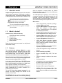
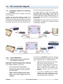
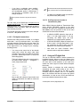
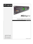
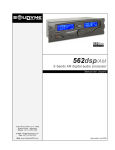
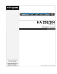
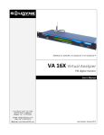
ADA102 CODER / DECODER TCP/IP studio-to-transmitter link User's manual SOLIDYNE SRL 3 de Febrero 3254 (C.P. 1429) Buenos Aires - Argentina Tel.: +54 11 4702 0090 Fax: +54 11 4702 2375 www.SolidynePRO.com [email protected] Last revision: May 2011 Firmware 2.05 Table of contents Overview - ADA102 CODER / DECODER . .5 1.1 About this manual..................................................5 1.2 What's in the box?..................................................5 1.3 Features..................................................................5 2.2 ADA102 at the Transmitter Plant Brief guide ....................................................14 2.2.1 Installation.........................................................14 Step Step Step Step Step Step Section 1 - Hardware and connections .....7 1.1 General connection diagram ..................7 1.2 Rear panel.................................................7 1..............................................................................14 2..............................................................................14 3..............................................................................14 4..............................................................................14 5..............................................................................14 6..............................................................................14 2.2.2 ADA102 working as decoder............................14 Step 7..............................................................................15 Step 8..............................................................................15 1.2.1 Power supply.......................................................7 1.2.2 Audio inputs and outputs...................................7 2.2.3 Status screen.....................................................15 Balanced input/output connections:......................................7 Unbalanced connections: .....................................................7 2.3 Advanced settings..................................17 1.2.3 LAN port...............................................................8 1.2.4 USB port...............................................................8 1.2.5 Serial port.............................................................8 1.2.6 Remote control....................................................8 1.2.7 MPX output (optional ADA102mpx)...................8 1.2.8 Reset.....................................................................8 2.3.1 Setting temporary IP address using ARP command ...................................................................17 2.3.2 Remote control..................................................18 2.3.3 Serial port...........................................................18 2.3.4 About audio settings.........................................19 1.3 Frontal panel.............................................9 2.3.5 Calculating the bit rate......................................19 2.3.6 Emergency pendrive.........................................20 1.3.1 Level indicators...................................................9 1.3.1.1 VU mode Tx/Rx.........................................................9 1.3.2 SATUS LED's...............................................................9 1.3.2 Headphones output.............................................9 1.3.3 Input Gain.............................................................9 1.3.4 Output Gain..........................................................9 1.4 STL connection diagram........................11 1.4.1 Connection diagram for streaming transport..11 1.4.2 Levels adjustment.............................................11 1.4.2.1 Audio processor locates at the studios with analogical connections........................................................11 1.4.2.2 Full digital connections............................................12 1.4.2.3 Audio processor locates at transmission plant.......12 Encoding & Frequency....................................................19 2.4 Other connection modes........................21 2.4.1 Half-duplex link with unknown IP at the transmitter plant.........................................................21 2.4.2 Full-duplex link with unknown IP at the Studios........................................................................21 2.4.3 Link with repeaters...........................................22 Section 3 - Technical specifications........23 Digital Streaming Input / Output ..............................23 Other features.............................................................24 MPX output (modelo ADA102mpx)...........................24 1.4.3 Using an RF digital link....................................12 Section 2 - Software settings....................13 2.1 ADA102 into the Studios – Brief guide..13 2.1.1 Entering to ADA102...........................................13 Step Step Step Step 1..............................................................................13 2..............................................................................13 3..............................................................................13 4..............................................................................13 2.1.2 Set the working mode.......................................13 2.1.3 Audio options....................................................13 Step 6..............................................................................13 2.1.4 Status screen (home)........................................14 SOLIDYNE ADA102 CODER/DECODER Page 3 SOLIDYNE ADA102 CODER/DECODER Page 4 Overview 1.1 ADA102 CODER / DECODER About this manual Solidyne® All rights reserved. No part of this document can be copied or reproduced. All information is subject to change without notice. All mentioned trademarks belong to their respective owners and are used for reference only. The exclamation icon within a triangle that appears in this manual is intended to alert the user to the presence of important instructions on the operation and maintenance (servicing) of the equipment. drops by congestion or network failure, the ADA102 Decoder will start to play audio files from USB device until the connection restored. The serial port support "gateway". From studios, using a computer connected to the ADA102 encoder, you can command a remote device directly connected to the ADA102 decoder at the transmitter plant, as if the device was connected directly to the computer on Studio. Main features • Can be set as Encoder or Decoder by settings, using the WEB Control Panel. • Generates MP3 streams at adjustable bit rates (VBR) from analogue or digital (AES-3) sources. Compressed audio is not supported for full-duplex transmissions. • Generates G.711 (aLaw/uLaw) streams at 8 or 48 KHz sample rate from an analogue source. • Generates PCM (16 bit) streams from 8 up to 48KHz sample rate from an analogue source. • Supports Full-duplex for PCM and G.711. • 10/100 Mbit Ethernet connection supports automatic network configuration (BOOTP, DHCP, AutoIP and IPzator) as well as manual static IP configuration. • Features SonicIP® announcing the IP address on power up over the audio outputs. • Control and configuration using a standard web browser. • Remote monitoring using SNMP. • Remote controllable using HTTP, TCP and UDP. The coded output is an RJ45 connector compatible with Ethernet TCP/IP networks. ADA102 has analogical audio inputs (balanced) and digital AES-3 or S/PDIF. • 4 inputs to manage 4 switches at the remote device. • Serial port gateway. At the other end, an ADA102 set as DECODER convert the incoming stream (from Internet or microwave link 802.11.x) into analogue audio signal or a digital stereo AES-3 (S/PDIF compatible), sent to transmitter. • In half-duplex the unit automatically recognizes the audio format of incoming streaming. • Balanced analogue inputs / outputs. Model ADA102mpx decoder incorporates a third type of output: Baseband MPX for direct connection to a broadcasting FM transmitter. • Base band MPX output for FM (optional). • USB Pen Drive for emergency audio. If the streaming is lost due to network failure, the decoder plays from USB device until streaming restores. 1.2 The pencil icon that appears in this manual is to alert the user to the presence of notes, suggestions and examples about the operation. What's in the box? Inside the box you will find the following: 1 ADA102 Encoder / Decoder (rack module).1 AC power cord.1 crossed LAN cable Printed user manual (this manual).Warranty certificate.- Please check the items when receive it to verify that all components are okay. 1.3 Features The encoder/decoder Solidyne ADA102 is a stand alone streaming generator, designed to work as Studio to Transmitter Link (STL). Encoder works with stereo audio signals turning it into an MP3 or PCM audio streaming, under different modes (see specifications). The unit has four relay remotely managed. At the encoder, four inputs manages four switches on the decoder, and vice versa. The USB port lets you connect a pendrive when the ADA102 works as a decoder. If the incoming streaming SOLIDYNE ADA102 CODER/DECODER Page 5 SOLIDYNE ADA102 CODER/DECODER Page 6 Section 1 Hardware and connections 1.1 General connection diagram 1.2 Rear panel Remote control FM base band (MPX) 1.2.1 Ethernet Streaming RS-232 USB RESET Power supply AC wires do not have to be mixed with audio wires, especially with analogical ones. Remember that all audio installation must have a trustworthy grounding. We recommend accomplishing with the standards - Article 810 of the National Electricity Code (NEC); ANSI/NFPA Nº 70-1984 in USA; IRAM 2379 and 2281-3 in Argentina. This standard provides information and guidelines for a consistent grounding. Audio inputs and outputs Analog inputs and outputs are electronically balanced. The inputs are “bridging” type, with impedance greater than 10 KOhms. The connectors used, as is standard, are female XLR-3 for the inputs and male for the outputs. SOLIDYNE Balanced analogue inputs AES-3 output 110/220 AC selector Balanced analogue outputs Take specially care with the phase. Always CHECK the correct position of the VOLTAGE SELECTOR (200/240V o 100/130V, according to the country) 1.2.2 AES-3 input Use one pair shielded audio cables of good quality, preferably with double shielding. The maximum length recommended is 30 mts, although in special cases it's possible to achieve 100 mts. accepting a little loss at high frequencies. The connection of this cables are made as is standard. See the following table: Balanced input/output connections: 1 = GND 2 = balanced positive phase (+) 3 = balanced negative phase (-) Unbalanced connections: Inputs: Signal = 2; GND = join 1 y 3 Outputs: Signal to pin 2; leave pin-3 unconnected. GND = pin 1 ADA102 CODER/DECODER Page 7 AES-3 input and output cables connect as following: XLR Signal 1 GND 2 AES3 (1) 3 AES3 (2) 1.2.6 Remote control Each unit has four inputs and four outputs for remote control. Each input can controls a switch off the remote unit. Inputs are type “dry inputs”. To enable an input (input “on”) send it to a GND pin of DB-15. AES3 standard connection S/PDIF device can connect to AES-3 input/output of ADA102 using an S/PDIF to AES-3 adapter. No software setting is needed to enable AES-3. Decoded audio are always sent to Analog and AES-3 outputs. The output switches 1 and 2 are "open collector" type (used for example to command external control circuit). Switches 3 and 4 are mechanical relays that can manage up to 1 A @ 24 VDC. DB-15 pin out: 1.2.3 LAN port Standard Ethernet RJ45 10/100 to connect the unit to a switch/router to send or receive audio streaming. 1.2.4 USB port Lets plug in a flash memory storage (Pen Drive) when the unit works as a decoder, so that in case of loss of streaming, the decoder switches to the Pen Drive to continue with the audio playback. USB 1.1 compatible devices are supported, with the following limitations: • Only mass storage devices are supported. • HUB's are not supported (some flash drives have an internal HUB) • 4GB is the maximum capacity. If the flash disk is larger, create a 4 GB partition. Only the first partition is supported. • First partition mus be FAT16 format. If your computer does not recognize the pen drive, the following procedure can help you find the reason: • Open an Internet browser, enter the ADA102 IP address followed by /status (i.e.: 102.168.0.110/status). • Scroll down until "USB device info" • Check if "Filesystem type” is "FAT16". If it's "FAT32", reformat the USB memory as FAT16. The USB must contain a playlist file named "playlist.m3u" which determines the order in which MP3 files are played. This playlist can be created with the Winamp audio player (www.winamp.com) or any software that generate .m3u playlist files. When the USB is puged, ADA102 will reboot to detect the device, so audio output will be muted by few seconds. 1.2.5 Signal PIN Signal 1 Input 1 5 Switch 1 (open collector) 2 Input 2 6 Switch 2 (open collector) 3 Input 3 7 y 14 Switch 3 Relay, normal open 4 Input 4 8 y 15 Switch 4 Relay, normal open 9 a 13 GND 1.2.7 MPX output (optional ADA102mpx) The model ADA102mpx includes a stereo coder that generates the FM baseband signal. This output is connected to an FM transmitter. The MPX cable is a RG-59 (coaxial 75 ohms), like the used for CATV. The output connector is BNC. The maximum length recommended for this cable is 25 m. Take care with the grounding; although this rarely is cause of problems because all Solidyne processors have MPX differential outputs, that is to say, with the ground isolated from the cabinet, to avoid ground loops. If some residual humming appears when the system is on the air; power off ADA102. If the humming disappears, check the input connections at the decoder. If, however, the humming continues (and only disappears unplugging the MPX cable), this indicates some important problem with the grounding. When enters to the transmitter through the MPX input, make sure that the internal pre-emphasis network IS DISCONNECTED (that is to say, flat response from 20 Hz to 100 KHz). Contrary, when use an external stereo coder, make sure that the generator INCLUDES the pre-emphasis curve. This is due that ADA102 audio output DOES NOT INCLUDE pre-emphasis (only the MPX output has pre-emphasis). Serial port The serial port is used to command, from the studios, a device located in the transmitter plant as if it were directly connected to serial port of the computer at the Studio. For this ADA102 generates a gateway for transporting serial data transparently through the network (see "2.3 - Advanced Settings). The connection requires a standard RS232 cables. SOLIDYNE PIN 1.2.8 Reset Pressing this button restarts the unit. Press and hold for 10 seconds to reload the factory defaults. If you start your computer holding down the button for 5 seconds, ADA102 starts in “firmware update” mode. ADA102 CODER/DECODER Page 8 1.3 Frontal panel Headphones Level indicators Shows the input level (coder mode) or the output level (decoder mode). 1.3.1 VU MODE STATE Output gain Input gain (analogue) In normal conditions: Level indicators ADA102 has two needle-type VU meters that shows the real peak value of audio signal. 1.3.1.1 VU mode Tx/Rx This button changes the signal that the VU shows. Tx shows the level of the analogue input. Adjusting the input level you are adjusting the transmission level. This is the usual work mode in the Studios. Rx shows the output level of analogue output and streaming. This is the usual work mode in the Transmitter Plant. Green LED Red LED OFF BLINKING ON OFF The application is operational. ON ON Reset Button is being pressed, the unit will reboot after releasing the button. 1.3.3 State Application is detecting USB devices or announcing the assigned IP address using SonicIP technology. Headphones output Gives the output signal with headphones level, to monitoring. The level changes with the output level control. Level indicators do not work with AES-3 signals. 1.3.4 1.3.2 SATUS LED's During the initial boot up sequence the 2 status indicator LEDs can indicate the following anomalies: No Application loaded (only bootloader) or started with hold reset button during power up: The green LED is on and the red LED blinks. Application starts (boot-up sequence): Input Gain Manages the input gain of the analog inputs. Adjust this level to reach 0 VU with signal peaks. To see the input level the VU meter must be in Tx mode. 1.3.5 Output Gain Manages the analog output level. At 0 VU the output level is +4 dBm. To see the output level the VU meter must be settled as Rx from rear panel. First the red goes on and the green LED blinks once. Then during the startup the green and red LEDs blink. During DHCP the red LED blinks with a continuous cycle . The green LED blinks five times and then pause four times. If an error is detected the red led remains on and the device resets itself after the green LED has indicated the error as follows: ERROR Green LED blinks Corrupt application or IP address conflict five times The Network hardware could not be initialized or a Corrupt MAC address three times SOLIDYNE ADA102 CODER/DECODER Page 9 SOLIDYNE ADA102 CODER/DECODER Page 10 1.4 STL connection diagram 1.4.1 Connection diagrams for streaming transport The figures above shows two examples of streaming link in FM stations. In diagram (a) the audio processor is located at the studies, and carries the processed audio to a ADA102mpx connected directly to transmitter. In this way the processor works with the audio signal directly from the console, and ADA102 carries the processed audio. This is the recommended configuration for FM. The diagram (b) shows a chain of 100% digital audio, using inputs and outputs AES-3. In this case, the processor appears in transmission plant, which is processing the audio decoding of MPEG streaming. The output of MPX audio processor is connected directly to the transmitter. In AM stations, the audio processor must be close to the transmitter to maintain a DC coupling that allows the asymmetric modulation. Figure (a) – STL with audio processor at the Studios Fig.(b) – STL using an digital audio chain. For AM stations, the audio processor must be next to the transmitter 1.4.2 Levels adjustment 1.4.2.1 Audio processor locates at the studios with analogical connections When the audio processor is at the Studio, connected by analog input – case (a) mentioned above – the input level of ADA102 CODER is a critical issue. • • • Choose a high density musical program. Play on-air the music and check the audio processor to verify that the AGC compression be 10 dB or higher. Adjust carefully the ADA102 input gain to obtain a 0 VU deviation with the peaks. Needle must never overpass the 0 VU indication. SOLIDYNE At the other end, ADA102mpx receives the streaming. The incoming streaming is decoded and sent to MPX stage. To adjust the 100 % of modulation proceed: • ADA102mpx has two presets at the rear panel: MPX level and 19 kHz Pilot Tone level. • Playing the same high-density song used to adjust the CODER, adjust the MPX level preset to obtain 100% of modulation at the transmitter. Read this value at the exciter VUmeter • If you have a modulation meter available (Solidyne VA16, Belar, Innovonics, etc.) we recommends to use the measurements of this instrument instead of the exciter value. ADA102 CODER/DECODER Page 11 • If you have a modulation meter available, adjust the pilot tone depth to 8% / 10% using the correspondent preset of ADA102mpx. If you don't have a modulation meter, do not change this preset. The knob level at the front panel only takes effect over analog inputs, and the VU meters do not operate with digital signal. • To adjust the modulation depth, proceed like the previous case (MPX preset). Do not push the screwdriver. The preset can be broken. The level knob at the ADA102mpx front panel do not changes the MPX level. Only take effect on the level of balanced outputs, so it must be adjusted only to obtain a visualization at the VU-meters, which will indicate that input streaming is present. The internal input gain (software) do not be changed. It must be -1 dB (default value). 1.4.2.3 Audio processor locates at transmission plant When ADA102 links the Studios to Transmission Plant, where ADA102 DECODER connects to the audio processor; the audio level managed by ADA102 link is not critical, since the processor at the end of chain controls the level sent to the transmitter. • In ADA102 CODER, adjust the input gain to reach 0 VU with signal peaks. If you are connecting the AES-3 input, the level adjustment is no needed (neither possible). • In ADA102 DECODER, adjust the output level knob to reach 0 VU with signal peaks. If you are connecting the AES-3 output, the level adjustment is no needed (neither possible). • Now follow the Audio Processor user's manual in order to adjust the modulation. 1.4.2.2 Full digital connections Whenever the audio processor is located, in a full digital audio chain – case (b) mentioned above – the controls on frontal pannel do not take effect over the signal. The adjustment is made from web control pannel. The level of the digital audio is not changed by the encoding– decoding process. • You must set the output level of the decoder output (wich excites the stereo coder input) according to the output level (dBfs) of the audio processor. Default output level is -1 dB (for use with analog signals). This level is adjusted from web control pannel, in the section Basic Settings → Configration → Audio (Output Audio Level). Next, a table with reference Output Audio Level values, A continuación una tabla con valores de referencia. Procesador output (dBfs ) Decoder Output - 3 dBfs - 6 dB * - 6 dBfs - 3 dB - 9 dBfs 0 dBfs 1.4.3 Using an RF digital link The use of a ADA102 CODER in studios connected to broadband Internet, allows to cover any distance from studios to transmitter plant. This solution can be used to STL links and for radio networks, so one coder from studios can send a signal to several slaves throughout the country. Another solution to transport the audio streaming maintaining the great sound quality at low cost: a microwave link for 5.8 GHz (or 2,4 GHz in some countries) using the standard 802.11.x. This band is free in all countries and does not require any special authorization. It is able to cover 45 Km and should not have major obstacles between the two sides. For details, please contact us ([email protected]). * Value for Solidyne digital processors SOLIDYNE ADA102 CODER/DECODER Page 12 Software settings Section 2 2.1 ADA102 into the Studios – Brief guide ADA102 can be settled to work as a coder, as decoder, or both at once for full-duplex connections. In this example we assume a unidirectional link (halfduplex) between Studios and Transmitter Plant. In the Studios the ADA102 works as ENCODER, generating and sending an audio streaming to the transmitter. At the transmitter plant ADA102 receives the streaming and decode it to audio. 2.1.1 Entering to ADA102 ADA102 is configured using a web browser. By default, ADA102 uses "Dynamic IP" so that when connected to a LAN, gets an IP address via DHCP (the router assigns an IP). The procedure is as follows: Step 5 Since this unit will send streaming from the studios, is set as an encoder to generate the streaming. For make this, go to option “Configuration” and select “Basic settings” in the left drop-down menu. • Define “Stream method” as “Push (RTP)” • In the field URL enter the IP or DNS, and the destination port for the streaming. ADA102 CODER will stream directly to this IP address. • Press “Apply” to confirm these values. Step 1 Plug the unit to the LAN using a standard RJ45 cable. Step 2 Plug a headphone to the frontal panel connector. Please have your pen and paper to write the IP address that will be announced. The level of the headphones is managed by the output gain knob. If you don't hear the IP, check this knob. Step 3 Power on ADA102 (main switch locates at the rear panel). The ADA102 CODER will search for a DHCP server to get an IP address. Once obtained the IP, your ADA102 is now ready to start working. Green Led on front panel will blink. If no DHCP server is found then ADA102 will search the network for a free IP address (this could take up to 5 minutes). If all is right, DATA LED at the front panel will blink. If the front LED's (“data” and “error”) stay dark check the power cabling. If it still fails, please contact to Solidyne. This destination IP address is the external address of the network where the decoder is located (the static IP assigned by your ISP). When packets reaching the router/firewall at the other end, they should be redirected to the local IP address of ADA102 DECODER (eg. 192.168.0.30). As the CODER transmit to a specific IP address and port, all packets arriving at these Port in these address must be forwarded to the DECODER, wich converts to audio. Identify which packages must be address using the “port forwarding”. 2.1.3 Audio options Step 6 Step 4 Open an Internet browser (i.e. Firefox, Internet Explorer) and enter the announced IP address. The web control panel will appears on screen. 2.1.2 Set the working mode The STATUS screen indicates the current settings. Go to the options that appears at the top of the window. Click on “Location” and choose 'Studio Encoder'. SOLIDYNE Input source: Define the input (analogue or AES-3). Default is “Analogue”. Format: Define the streaming format. Default values are (must be changed only if the Internet bandwidth is limited): ADA102 CODER/DECODER Page 13 encoder)”. • • • Format: MPEG stereo Sample rate: 44.1 KHz (MP3) Quality: 7 highest Stream mode: Shows the current event settings to start the transmition to remote device. This settings generates a streaming of 192 kbps. 2.1.4 Keep-alive: Shows the current keep-alive settings. Connection status: If the connection was successful this field appears in green showing the destination IP (Established to xxx.xxx.xx.xx). In case of connection failure, the field appears in red. Status screen (home) Incoming Stream: State of incoming streaming. In this case is inactive because the device is working only as coder. Outgoing Sream: State of outgoing streaming. This field appears active only when the device works as coder. Audio input: show the input assigned by settings (analogue or digital). Audio Format: Format used to codifies the streaming. Input/Output audio level: Real level of the audio signal, expressed in dBfs. Relay 1..4: Behavior of switches on local device. Remote inputs: State of the control inputs at the remote device (Transmitter plant). When an input is “on”, the correspondent gray box changes to green. Site type: Shows the working mode. In this case the device is located at the Studios working as CODER, sending coded audio to transmitter plant (“Studio Local inputs: State of the inputs of local device. Local Relays: State of local switches (which are commanded by the remote device). 2.2 ADA102 at the Transmitter Plant – Brief guide 2.2.1 Instalation Step 5 Step 1 Plug the power cord to AC outlet. Check the voltage switch at the rear panel. Step 2 To configure the unit, you must access the web control panel. By default, ADA102 uses "Dynamic IP" so that when connected to a LAN, gets an IP address via DHCP (the router assigns an IP). The procedure is as follows: Step 3 Plug the unit to the LAN using a standard RJ45 cable. Step 4 Plug a headphone. Please have your pen and paper to write the IP address that will be announced. The level of the headphones is managed by the output gain knob. If you don't hear the IP, check this knob. SOLIDYNE Power on ADA102 (main switch at the rear panel). The ADA102 CODER will search for a DHCP server to get an IP address. Once obtained the IP, your ADA102 is now ready to start working. Green Led on front panel will blink. If no DHCP server is found then ADA102 will search the network for a free IP address (this could take up to 5 minutes). If all is right, DATA LED at the front panel will blink. If the front LED's (“data” and “error”) stay dark check the power cabling. If it still fails, please contact to Solidyne. Step 6 Open an Internet browser (i.e. Firefox, Internet Explorer) and enter the announced IP address. The web control panel will appears on screen. 2.2.2 ADA102 working as decoder At the transmitter plant, the unit works as pasive receiver, receiving the streaming from ADA102 CODER, so it must be set as “Transmiter decoder” from the option “Location”. ADA102 CODER/DECODER Page 14 Step 7 When the device is set as “Decoder”, it loads the default values for receive streaming, and usually you don't need to change this values (with the exception of port numbers and IP addresses). Next, the most important settings are descripted. Keep-alive: Displays the current configured keep-alive strategy. Click on “Configuration → Streaming” Step 8 In the field “Port” enter the same port number used in ADA102 CODER. Hit “Apply” to confirm. Step 9 At the decoder, you must to pay attention to the buffer size, which is the memory that holds the incoming streaming audio to avoid drops. These interruptions occur when the bandwidth is insufficient for the transmitted audio quality and can be solved by increasing the buffer size. But note that larger buffer size will cause greater delay time. The appropriate value depends on the bandwidth of the network and type of audio streaming. Buffer size is expresed in miliseconds. For uncmpressed PCM streaming times of 40/80 mS works find. For coded formats larger times are nedded due to the times involved in the decoding process (see “2.3.5 - About audio options”). No other value must be defined. ADA102 automatically recognize the incoming streaming. The audio quality is defined in the CODER. Emergency Pen Drive: Remember that you can connect an USB device (Pen Drive) in the USB port. In case that the streaming lost by network failure; ADA102 will play audio from USB device until the connection restores. 2.2.3 Connection status: Displays the actual connection state. Incoming stream status: It shows the actual incoming stream status (ON/OFF). Outgoing Sream: It shows the actual outgoing stream status (ON/OFF). Audio input: selected input source (analogue or digital). Audio Format: In a half-duplex link the audio format is defined by the CODER. DECODER automatically detect the incoming streaming format, showed in this field. Input/Output audio level: Real level of audio signals, expressed in dBfs. Relay 1..4: Shows the configured event for local relay switch. Remote inputs: State of the control inputs at the remote device (Studio). When an input is “on”, the correspondent gray box changes to green. Local inputs: State of the inputs of local device. Local Relays: State of local switches (which are commanded by the remote device). Status screen Site type: Shows the working mode of the unit. In this case the device woks as DECODER, located at the Transmitter Plant. It works as pasive receiver decoding the incoming streaming from Studios (“Transmitter decoder” ). Stream mode: Displays the current configured event to start streaming to the remote destination(s). SOLIDYNE ADA102 CODER/DECODER Page 15 SOLIDYNE ADA102 CODER/DECODER Page 16 2.3 Advanced settings 2.3.1 Setting temporary IP address using ARP command This procedure is used to temporarily set the IP address for first time browser access to the ADA102, in the case where you have no LAN and wants to access from a Notebook. Step 5 Now we have to make the ADA102 listen to the IP address “192.168.0.6” using the Telnet command. To do so type into the command window: telnet 192.168.0.6 1 and hit the “Enter” key After this procedure the temporary IP will be active only as long as the ADA102 stays powered. After a restart the procedure has to be repeated unless you have configure it with a static IP address. (the number “one” must be there for this command to work correctly !!!). The ADA102 will refuse the connection on port 1 immediately but will be available for web access on the IP address used as long as the device Step 1 Use either a “crossover” network cable between the ADA102 and the PC or use two network cables to connect the ADA102 and the PC to a network switch and power the ADA102. stays powered. Make sure that you have a valid IP address configured on your PC (e.g. 192.168.0.2). Step 2 Open a command window. Windows: click on “Start”, click on “Run..”, in the “Open” field type cmd , click on “OK”. Step 6 To check if the ADA102 is responding you can use the ping command again. To do so type: ping 192.168.0.6 and hit the “Enter” key. If you do get a reply the IP address 192.168.0.6 can be used to access the ADA102 using a web browser. If you do get “request timed out” then please repeat step 6 carefully (you most likely mistyped the telnet command) or repeat the entire procedure. OSX / Linux: Open a terminal window Step 3 Please proceed to step 4 if you used a “crossover” network cable in the preparation step above. To ensure that we use a free IP address (not already used by another device in the network) we have to use the Ping command. In this example we assume the PC to have the IP address “192.168.0.2” and want to check if “192.168.0.6” is free. 2.3.2 Static IP You can define a static IP. The advantage is that a known IP allows you to access to the web panel, in case that you requires change settings; without the necessity of listen the audio to know the IP (voice IP announced on start up). By default the IP address is set to 0.0.0.0 (Dynamic IP disabled). To change it, go to “Configuration → Network”. Use SonicIP: If set to "yes", the device will announce its To do so type ping 192.168.0.6 and hit the “Enter” key. IP address over the audio output. Default: "yes". If you get a reply (IP already used) then try to ping another IP until you find one that is not used. If the request times out (no reply) then the “pinged” IP is free and we can continue with the next step. IP Address: Enter the IP address of the device, e.g.: Step 4 Netmask: Enter the 4 values of the desired Static IP e.g.: Look for the Solidyne ADA102 MAC address printed on a label placed on the rear panel (12 hex digits, separated by a hyphen every 2 digits). Type into the windows command window: arp -s 192.168.0.6 00-08-E1-00-B1-77 and hit the “Enter” key (replace the digits according to your devices MAC address). On a OSX or Linux system type into the terminal: arp -s 192.168.0.6 00:08:E1:00:B1:77 SOLIDYNE "0.0.0.0" for automatic discovery (DHCP/Bootp, IPzator, AutoIP) "192.168.0.12" for an internal LAN. Default: "0.0.0.0" "0.0.0.0" for a default Netmask depending on the used IP Address. "255.255.255.0" for a C class network Default: "255.255.255.0". Gateway IP Address: Enter the IP address of the Gateway e.g.: "0.0.0.0" for "192.168.0.1" for a Gateway in a LAN. ADA102 CODER/DECODER no Gateway The Gateway has to be set only when connecting to other devices over the WAN (through a router). Default: "0.0.0.0" Page 17 Primary DNS: Enter the primary DNS IP address so the device con connect to URLs (e.g. www.radio.com). Example: "195.186.0.1" Default: "0.0.0.0". Alternative DNS: Enter the alternative DNS IP while incoming audio buffer is empty. "always OFF": Relay will be OFF always. Default setting is "always OFF". address in case the primary DNS is not reachable. Example: "195.186.4.111" Default: "0.0.0.0" Syslog Address: Destination address for syslog messages sent by the BCL program via the SYSLOG command. Set this to your syslog logging machine, if your syslog messages are recorded centrally. If set to 0.0.0.0, syslog messages are broadcast. Default: "0.0.0.0" DHCP Host Name: Name of the device sent in DHCP request. If left empty, a name based on the device's MAC address is generated automatically. Enter up to 15 Characters. Web server port: Defines the port where the webserver of the Solidyne device can be reached. If set to "0" the default HTTP port (80) is used. 2.3.3 By default, relay Nº1 is ON while the connection is alive. Relays 2, 3 and 4 remain OFF. SNMP Destinations IP(s) For alarm sending, set the desired list (colon separated) of SNMP trap receivers. Remote control ADA102 has four electronic switches managed by the remote Solidyne device. Four inputs at the CODER manages four switches in the DECODER, and vice versa. In addition, switches can be controlled by other events. In the control WEB panel, go to option “Configuration” of main menu. Section “I/O and Control” allows to define the behavior of electronic switches. Available options are: "ON while remote Input X ON": Relay will be ON while the button with proper Input number is pressed on remote device. "ON while connection ON": Relay will be ON while connection is defined by keep-alive. "ON while connection OFF": Relay will be ON while disconnection is defined by keep-alive (Alarm: partner missing!). SMTP Server IP/DNS For alarm sending, set the IP address or DNS name of the SMTP server. Local e-mail (FROM:) FROM mail address, for SMTP alarm service. Destination e-mail(s) (TO:) TO mail address, for SMTP alarm service. Multiple email addresses have to be separated by colon. 2.3.4 The ADA102 serial port allows control from a PC in the Studios a remote device located in the transmiter plant as if it were connected directly to the serial port of the computer at the Studios. "ON while IN audio ON": Relay will be ON while audio input is above "Input Trigger Level" (with "Inactivity Timeout" delay). • "ON while IN audio OFF": Relay will be ON while audio input is below "Input Trigger Level" (with "Inactivity Timeout" delay) • "PULSE ON with IN audio change": Relay will be pulse ON if audio input changes its state via "Input Trigger Level" (with "Inactivity Timeout" delay). "ON while incoming stream ON" Relay will be ON while incoming audio buffer is full. "ON while incoming stream OFF": Relay will be ON SOLIDYNE Serial port A the Studios, the computer connects to ADA102's serial port, using null-modem cable (crossed RS232). At the Transmitter Plant, a device (i.e. a broadcast RDS coder) connects to the ADA102-s serial port, using a standard RS232 cable. You must set the port to RS232 “tunneling”. In the WEB control panel, hint the option “Configuration”. In section “Serial” the field “UDP/TCP Port for COM1” allows to enter a port number to serial communication. You must use the same port in both CODER and DECODER devices. ADA102 CODER/DECODER Page 18 The option “Serial 2” is not implemented. Leave “UDP/TCP Control Port for COM2” as zero. 2.3.5 Overhead/s = Overhead/Packet x Packet/s Total Bit Rate (Kbit/s) = Audio Data Rate (Kbit/s) + Overhead/sec (Kbit/s) (1Kbit = 1000 bits) About audio settings Encoding & Frequency Audio Format The unit supports the following audio formats: • • • MPEG1 / MPEG2 (solo half-duplex) uLaw/aLaw PCM MSB/LSB first The passive receiver of a half-duplex system automatically recognizes the audio format but only for audio formats with fixed content. AES3 / S-PDIF input uses MPEG1 and the sample rate detects automatically (32, 44.1 o 48 KHz). Remember: The playback buffer size is a very important question. This value expresses the buffer size in miliseconds. Smaller values minimize the delay, but increase the chance of audio drops. The optimal value depends on audio format and sample rate. Audio Total Bit Packet/sec Overhead Data Rate Rate (Wireshark) (bit) (Kbit/s) (Kbit/s) MPEG1 48KHz quality 0, stereo 88 41.7 652 115.2 MPEG1 48KHz quality 4, stereo 144 41.7 652 171.2 MPEG1 48KHz quality 7, stereo 192 41.7 652 219.2 MPEG1 48KHz quality 4, mono 96 41.7 652 123.2 MPEG1 44.1KHz quality 0, mono 65 38.3 652 90 MPEG1 44.1KHz quality 4, mono 90 38.3 652 114.97 MPEG1 44.1KHz quality 7, mono 140 38.3 652 164.97 MPEG2 16KHz quality 0, mono 28 27.8 652 46.12 MPEG2 16KHz quality 4, mono 44 27.8 652 62.12 MPEG2 16KHz quality 7, mono 64 27.8 652 82.12 Audio Format (STL) MP3 baja tasa de bits 400 mS MP3 alta tasa de bits 200 mS ALaw 8 Khz, mono 64 50 620 0.09 PCM 44.1/48 KHz 40 mS PCM MSB 16 bit 8 KHz mono 128 50 620 0.16 176.4 50 620 0.2 PCM MSB 16 bit 12 KHz mono 192 50 620 0.22 PCM MSB 16 bit 16 KHz mono 256 50 620 0.29 352.8 50 620 0.38 PCM MSB 16 bit 24 KHz mono 384 50 620 0.41 PCM MSB 16 bit 32 KHz mono 512 50 620 0.54 705.6 70 620 0.75 PCM MSB 16 bit 48 KHz mono 768 75 620 0.81 PCM MSB 16 bit 8 KHz stereo 256 50 620 0.29 352.8 50 620 0.38 PCM MSB 16 bit 11.025 KHz mono 2.3.6 Audio Total Data Packet/sec Overhead Bit Rate Rate (Wireshark) (bit)1 (Mbit/s)2 (Kbit/s) Calculating the bit rate The final bit rate is the sum of the audio bit rate and encapsulation of audio packets make the network protocol used. For RTP the calculation is: The Ethernet total overhead per packet is 300 bit. The IP total overhead per packet is 160 bit. The UDP total overhead per packet is 64 bit. The RTP total overhead per packet is 128 bit (considering the enclousure MP3 MPA into the usable RTP overhead, that have a extra header of 32 bit). PCM MSB 16 bit 22.050 KHz mono PCM MSB 16 bit 44.1 KHz mono PCM MSB 16 bit 11.025 KHz stereo Total overhead of bits per packet = PCM MSB 16 bit 12 KHz stereo 384 50 620 0.41 Ethernet Overhead + IP Overhead + UDP Overhead + RTP Overhead = 652 bit PCM MSB 16 bit 16 KHz stereo 512 50 620 0.54 705.6 70 620 0.75 PCM MSB 16 bit 24 KHz stereo 768 75 620 0.81 PCM MSB 16 bit 32 KHz stereo 1024 100 620 1.08 1411.2 137 620 1.5 1536 150 620 1.63 PCM MSB 16 bit 22.050 KHz stereo The audio bit rate expressed in bits/s, but the overhead is expressed in bits/packet. So we have to translate the overhead (bit/packet) in overhead rate (bits/sec). For this we need to know the number of packets per second, depending on the audio format. It can be measured with a software network protocol analyzer such as the "Wireshark". SOLIDYNE PCM MSB 16 bit 44.1 KHz stereo PCM MSB 16 bit 48 KHz stereo ADA102 CODER/DECODER Page 19 2.3.7 Emergency pendrive ADA102 only recognizes files with extension “.mp3”. USB drive must contain the audio files placed directly in the root folder, and a playlist file named playlist.m3u, which determines the order in which files are played. The playlist can be created manually using a simple text editor (eg Windows Notepad) and then changing the file extension from .txt to .m3u. Here's an example: # sample playlist begin audio1.mp3 audio2.mp3 audio3.mp3 audio4.mp3 # sample playlist end As files are in the root folder, it is not necessary to indicate the path. Lines preceded by pound (#) are comments. The playlist can also be created using the audio player Winamp (www.winamp.com) or any other audio player to generate playlists in .m3u. Usually create an .m3u only requires to save the list of songs loaded on the player, as a playlist file type .m3u. Supported USB memory drives are detailed in “1.2.4 – USB port” SOLIDYNE ADA102 CODER/DECODER Page 20 2.4 Other connection modes 2.4.1 Half-duplex link with unknown IP at the transmitter plant 2.4.2 Full-duplex link with unknown IP at the Studios In this case requires a half-duplex link between Studios and Transmitter Plant. Studios have static IP but the Transmitter IP is unknown. The decoder (Transmitter Plant) will start the connection to the studios. This case is a full-duplex Studio to Transmitter link, but only the Transmitter Plant IP is known. The coder at the Studios starts the communication to that IP address. ADA102 at the Studios: ADA102 at the Studios: In the coder, go to “Configuration → Basic settings” and set the streaming method as “Pull (BRTP)”, the URL as “0.0.0.0” and enter the listening Port for BRTP. Hit “Apply” to confirm the values. In option “Location” set the device as “Studio Encoder/Decoder”. Go to “Configuration → Basic settings” and enter the IP address or URL for send and receive. Set the outgoing stream method as “Push(RTP)”. In URL enter the IP of decoder (the external IP address that router redirects to ADA102 decoder at the Transmitter Plant). The Port number is the the “Local Port” value assigned to the decoder in the Transmitter Plant. Set the incoming stream as “Pull(BRTP)” since the IP address of coder is unknown. In the field URL enter the IP of the transmiter plant (decoder) and the same port number assigned to de decoder. ADA102 at the Transmitter Plant At the Transmitter Plant, go to “Configuration → Basic settings” and set “Stream Method” as “Pull(BRTP)”. In field URL enter th eIP address or URL of the CODER in Studios. “Destination Port” must be the same assigned in the CODER. Hit “Apply” to confirm the values. In a full-duplex link, both units must work with the same audio format. MPEG are NOT SUPPORTED for fullduplex mode. SOLIDYNE ADA102 CODER/DECODER Page 21 ADA102 at the Transmitter Plant At the Transmitter Plant ADA102 receives the streaming from Studios. Set “Outgoing stream” as “Pull(BRTP)” since is the coder from studios who starts the connection. IP address is zero and the Port number mus be the used in the section “Incoming stream” in Studios. Set “Incoming stream” as “Push(RTP)” with IP address zero, since the coder starts the connection to the decoder. To implement this scheme, see your network administrator, because you need to configure the multicast routers. ADA102 at the Studios In this case ADA102 coder transmit to a multicast IP address. Coder works in mode “Multicast” (Configuration → Stream Method). ADA102 at the Transmitter Plant The decoder aslo works as “Multicast”. In the field URL you must define the same multicast IP used in the coder. 2.4.3 Link with repeaters In this mode the coder send streaming to several devices simultaneously. This configuration is common when you have a static IP to the “multicast” group and requires a half-duplex link. In both Studio ans in Plant, ADA102 is set as “Multicast” (Configuration → Basic settings → Stream Method). Multicast is a protocol designed for maximum efficiency of the networks when required simultaneous transmission from one point to multiple destinations. Both the transmitter and receiver use the same IP address, which should be in a special range of IP addresses for a multicast. This range includes addresses from 224.0.0.0 to 239.255.255.255. SOLIDYNE ADA102 CODER/DECODER Page 22 Section 3 Technical specifications Coder / Decoder Mode Analog Input / Output Digital IN / Out Frequency Response Distortion ADA102 is able to work as Coder or Decoder by software configuration. Full-duplex supported for non compressed audio streaming. Stereo balanced In / Outs -10 to + 15 dBu input level, regulated by front panel level control Max output level + 20 dBm over 600 ohms (at FSD level) 0 VU at meter: + 4 dBu out AES 3 professional balanced digital stereo IN / Out Z=110 Ohms. Full compatible S/PDIF Analog: 30 - 15.000 Hz +/- 0,5 dB @ 192 kbps Digital AES-3: 20 - 15.000 Hz +/- 0,1 dB @ 192 kbps Less than 0,01 % THD distortion, Analog or Digital @ 192 kbps Typical AES-3: 0,005 % @ 192 kbps Total Encoder+Decoder Dynamic Range > 70 dBA @ 192 kbps as encoder Noise Dynamic Range > 80 dBA @ 192 kbps as decoder Dynamic range AES 3: > 90 dBA @ 192, Total Encoder + Decoder Headroom Safety level from 0 VU meter to Full Digital Scale: 15 dB VUmeter Level Measures true peak level with a peak-hold system Channel Separation Better than 70 dB @ 1 kHz, Analog Better than 90 dB @ 1 kHz, Digital AES 3 Power supply 220-240V / 110 - 127 V 50 / 60 Hz, 15 VA Digital Streaming Input / Output Streaming connection Standard RJ45 Ethernet connection TCP/IP • MP3 Layer 1 (32, 44.1 and 48 kHz) • MP3 Layer 2 (16, 22.05 and 24 kHz) • G.711 (µLaw / A-Law 8 and 24 kHz sampling rate) Standards supported • 16bit PCM uncompressed (from 8 KHz to 48 KHz) MONO Streaming: MPEG1/2 Layer 3, VBR (Fs:48KHz): 72 76 80 88 96 112 144 160kbps STEREO Streaming: MPEG1/2 Layer 3, VBR (Fs:48KHz): 88 96 104 120 144 160 176 192kbps IP standard based protocols; TCP/IP, UDP, HTTP, ICMP, SNMP Protocols Supports BootP, DHCP and Auto IP. Supports RTP for low latency audio streaming. Latency (time delay) ADA102 has a latency of only 20 mS (uncompressed audio) on LAN The encoder uses Variable Bitrate Encoding (VBR) to realize optimal compression of the audio Variable Bit Rate (VBR) data. The setting of a fixed bitrate is replaced with setting a quality level that preserves audio Encoding quality in critical sections and enhances compression otherwise. SOLIDYNE ADA102 CODER/DECODER Page 23 Other features Port RS232 4 channels remote control lines Bidirectional serial port RS232 used for Audio Processor control from studios, RDS signal control or Transmitter remote control. Supports all speeds up to 96 Kbits/s Used for switch on-off transmitter, change to Day-Nigth power, change antenna array, etc. Four On-Off lines, 2 relay outputs (120 V - 1 A) and 2 open collector outputs (up to 24 V / 0,25 A ). In/Outs using D-15 female connector In case of Internet streaming interruption, ADA102 starts to reproduce a pre-recorded radio USB Emergency audio program. The user must record it on a Pen Drive, using MP3 format. The Emergency Radio Program could be only music or a complete program several hours long. MPX output (modelo ADA102mpx) Differential output, BNC connector, floating ground 50 ohms MPX Output Allows 45 dB canceling buzz & noise due to ground loops Level: Adjusted 0,5 to 4 Vpp from rear panel preset. Total Distortion THD less than 0.003 % at 1 kHz. Stereo Separation 75 dB at 400 Hz / > 70 dB; 30-15.000 Hz. 38 kHz Suppression 75 dB minimum below 100% modulation. 57, 76 and 95 kHz 75 dB minimum below 100% modulation. Suppression Pilot Level Adjusted 7-12 % from rear panel preset control Pilot Stability +/- 0.05 Hz, 0 to 50 °C. SOLIDYNE ADA102 CODER/DECODER Page 24