1
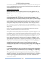
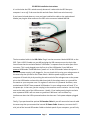
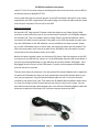
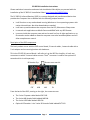
PC-IRS5-01 Installation Instructions Please read these instructions and watch the Installation Video before you proceed with the installation of the PC-IRS5-01. Installation Video: http://youtu.be/oS98E32VhB4 The PC-IRS5-01 Infrared Receiver (IRS5) is a custom designed and manufactured device that provides the Computer User or Builder with the following unique features: It will function on any motherboard running Windows or Linux operating systems with native eHome drivers. No driver downloads are needed. It will start up and shutdown the computer from the Off, Hibernate or Sleep states It controls such applications as Media Center and XBMC with any RC6 Remote It mounts inside the computer case and can be used in a line-of-sight application or an IR extender can be added to allow the computer case to be located anywhere and still allow complete user control. Description of the IRS5 components The basic product comes with the IRS5 control board, 3 internal cables, 1 external cable with a 5 volt adapter and a mounting bracket with hardware. This is the PC IRS5-01 control Board. I will refer to it as the IRS5 for simplicity. It has 4 rear connectors to which 3 internal cables connect. The 4th connector is used for the optional IR extender which is sold separately. IR Receiver Eye EXT USB Remote must see this MB 5V From the back of the IRS5, starting on the right, the connectors are: The 2-wire 5V power cable labeled 5VP CN3. The 4-wire MB Header Cable labeled MB CN4. The 4-wire USB Cable labeled USB CN1. Optional IR Extender. It is a 3-wire IR Extender Cable labeled EXT CN2. Page 1 PC-IRS5-01 Installation Instructions The first 3 connectors are for installing the 3 internal cables described below: a. The 5V Power cable attaches at 5V CN3. It is then run to the back of your case or somewhere in the case where you can mount this connector. Mounting the connector will require a hole in the case that is 3/8” in diameter. This cable is 20” long so keep that in mind when locating the IRS5 in the case. b. The Motherboard Front Panel Power/LED header control cable attaches to the MB FP Header. This has a number of small wires that are color coded and labeled. It connects the Front Panel header Power Switch and LED cables to the IRS5 while still allowing the cases power button and power LED to continue to function. c. The last of the standard cables is the USB cable that attaches at USB and to the motherboard internal USB 2.0 header. Finally, the optional IR Extender cable installation is similar to the 5V Power cable. It is mounted somewhere inside the case. It requires a hole that is ¼” or 7mm in diameter. If your case is a standard size with I/O plates for video and audio cards etc, you could use a blank I/O plate and drill the holes needed for mounting the cables. This cable is 20” long. Page 2 PC-IRS5-01 Installation Instructions Installation of the IRS5 control Board If you are going to mount the IRS5 in your computer case and control it without the extender cable, you will need to mount the board in your case so that the little black IR Receiver module (Eye) shown has a line of sight to your remote. Here is where the mounting bracket comes in. Install the IRS5 onto the bracket by placing the two small cylindrical spacers between the IRS5 and the bracket under the holes in the board and inline with the 2 outer holes on the bracket, then place the nylon washers on the top of the IRS5 above the holes and screw the two fasteners through the board and into the bracket. Gently tighten the 2 screws. Be sure that the IRS5 is on the bracket as pictured below with the little Black IR Receiver Eye facing the right angle portion of the bracket. You can mount the bracket in your case with double stick tape or you can use (2) 4-40 machine screws to mount the bracket through the threaded holes on the front of the bracket. When you find the spot where you are going to mount the bracket mark the spot where you will be drilling a hole for the little bump (Eye) on the Black IR Receiver module to look out and be seen by your remote. You could then drill the hole (about 1/8”) and mount the bracket. You can drill a larger hole and cover it from the inside with a small piece of Plexiglas which we can supply. The cables easily connect to the IRS5 so that should not be a problem if you mount the bracket now. By the way, as you can see in the picture, our 1U computer case has the window and bracket built-in if you are looking for a great small case. If you purchase our IR Extender cable and external module that comes in the optional kit, you can mount the IRS5 anywhere in the case with double stick tape as long as you have Page 3 PC-IRS5-01 Installation Instructions room to run the Power Cable and the Extender Cable to a point in your case where you can mount the required back plane connectors and still hook up the internal cables. Again, the Power and Extender cables are 20” long. Installation of the Internal Cables 5V Power Cable. Mount the female barrel connector that is on one end of the cable in a 3/8” hole in your case. You then plug the white connector into the IRS5 connector labeled 5VP CN3. MB Header Cable. Install by plugging in the white connector on the cable to the connector on the IRS5 labeled MB CN4. Then locate the Front Panel Power Switch header on your motherboard (MB). You can find out which header that is and where it is located in your MB User/Installation Guide. You will need to know the 2 pins on the header for the Power LED and the 2 pins that are for the Power Switch on the front of your computer. In most cases these 4 pins are side by side on the MB Front Panel header. You will also need to know in each of these pairs of pins which are the positive (+) and negative/ground (-) pins. If these pins are not labeled as such in your MB User Manual then you can easily find out by using a voltage meter. Be sure that you are working with the Front Panel Motherboard Header with this cable. Otherwise, the IRS5 could be shorted out and become useless. To use your volt meter, turn the power on to the computer at the power supply but do not press the power button. Remove the front panel connectors for the power switch and the LED from the MB Header. Touch the positive terminal (red) of your voltage meter set at 20 DCV to one of the Power Switch pins and touch the black terminal of your volt meter to a ground like the steel in your case. It will either read “0” or give you a reading of 3-5 volts. The pin that reads 3-5 volts is the (+). The other pin is the ground (-). If you do not find the LED polarity in the User Manual you can find out after you install the cables. When you turn on your system after installation, if the Front Panel LED lights up the way it did before the installation then you have installed it correctly. If it does not light then change the installation on the MB FP Header so that the female connector on the red wire labeled LED+ is switched with the black wire connector labeled LED- and plugged back onto the LED pins on the header. If you have not already done so, now you can plug the 4 female connectors labeled Power+, Power-, LED+ and LED- to the corresponding pins on the FP MB header that you identified before. Then plug the 4 male connectors onto the cables from the FP Power switch and FP LED making sure that they match the original connections that existed on your MB before you began this installation. That way the Power Switch and the LED will still be connected to the MB as they were before we added the IRS5 cable. Only now we also have the same connections for the IRS5. Page 4 PC-IRS5-01 Installation Instructions It is critical that the LED is wired correctly because it is what tells the IRS5 that your computer is on or off. So be sure that this and the Power Switch are wired correctly. If you haven’t already done so, once you have installed the cable on the motherboard header just plug the other end onto the IRS5 at the connector labeled MB CN4. The last standard cable is the USB Cable. Plug it into the connector labeled USB CN1 on the IRS5. Find a USB 2.0 header on your MB and plug the USB connector onto the 4 pin side. You will note that the red wire labeled “USB Power” is separate from the other part of the connector. This is only plugged onto the first pin of the USB header if your MB has a powered USB header. Some MBs have “power on” to the USB headers when the system is off but the power supply is still plugged in. You can check this by using your voltage meter in the same way that you did for the Power Switch. With the power supply on and the computer off check this pin by touching the red terminal of the voltage meter to the power pin on the USB header and touch the black terminal of the voltage meter to a ground like the metal on your computer case. If it registers 5 volts then it is powered. However, most motherboards DO NOT have powered USB headers. So your voltage meter will read “0” at the power pin. In that case, you do not plug in the connector on the red wire. Just let it hang next to the other part of the USB connector. Usually, if you inadvertently plug the red wire onto a powered USB it will not cause any problems. We leave it off to reduce any interference when the USB is powered and we also have our 5 volt power adapter plugged in. Finally, if you purchased the optional IR Extender Cable kit you will mount the internal cable the same way that you mounted the internal 5V Power Cable. However, to mount the 3.5 mini jack of the internal IR Extender Cable to the back panel of your computer, you will only Page 5 PC-IRS5-01 Installation Instructions need a ¼” hole. On the other end you would plug the white male connector into the IRS5 at the female connector labeled EXT CN2. You are now done with the internal portion of the IRS5 installation. We have 2 more simple steps before your IRS5 is operational. We need to plug in the external cables and then make sure that your computers OS is set up for the IRS5. External Connections We provide a 36” long external 5V power cable that plugs into our Power Supply Cable connector at the back of the case on one end and into a standard 5 volt USB power adapter on the other end. This is the adapter used to charge iPhones and Android devices. When connected, this cable is used to provide 5 volt power to the IRS5 that would normally come from the USB header on the MB. However, since most MBs do not have constant “power on” to their USB headers when in the off state, we supply the power with the adapter. The IRS5 must have power at all times to be able to turn the MB on and off as well as to send commands to the native eHome drivers on the MB. Neither this external power cable nor the internal 5V Power Cable that attaches to the IRS5 is necessary if your MB has the “power on” to the USB header when the MB is shut down. If you have a powered USB header on your MB then the red wire labeled “USB Power” must be plugged onto the first pin of the USB header. If you do not have powered USB headers then the red wire is not used. The only other external connection is for the optional IR Extender Module that is supplied in the optional IR Extender kit. After you have installed the internal IR Extender Cable in your case, you just plug the 6’ long IR Extender Module cable into the 3.5 mini jack that you installed on the back of your case. Then mount the IR Module Bud somewhere where there is a clear line of sight to the IR remote that you are using to control your system. You can even add an extra extender cable between your case and the IR Extender Module cable that allows you to place the IR bud up to 18’ from the computer that has the IRS5. Page 6 PC-IRS5-01 Installation Instructions That’s it for the actual installation of the IRS5 and the cables involved. It may look complicated when you start but you will see how easy it is because most connections can only be done one way based on the connector labels. The biggest decision is where to locate the IRS5 control board in your computer case and whether you need the IR Extender or not. The whole process will take less than an hour to complete. Software and System Set-up Even though you are done with the hardware there are a couple of settings that must be checked and/or changed so that your system and the IRS5 will operate properly together. In Windows click the “Start Button” then click “Control Panel” then “Hardware and Sound”, then “Power Options” and finally click “Change what the power buttons do”. Be sure that both the Power Button and the Sleep Button are placed in “Hibernate” or “Shut down”. We prefer “Hibernate” because your system will usually respond faster and without any unexpected results when you press the power button of your remote to turn your system on. However, in most cases, using the “Shut down” mode will create an equally effective result. If you use “Shut down” and your system comes back on to a screen that needs additional button presses from your remote in order to get back to your desired screen, then try it in “Hibernate”. Otherwise, both will turn off your system and turn it on again with just a press of the power button on your remote. By the way, the power button on your computer case will also operate as before the installation of the IRS5 to turn your system on and off. If you are not using a Windows OS then perform the equivalent adjustments in your OS. If you have any issues with the installation after reading these instructions and watching the assembly video then contact us at our technical support forum at: http://shop.inteset.com/boards Page 7