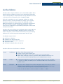
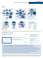
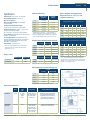
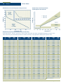
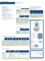
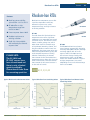
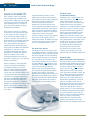
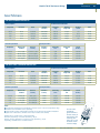
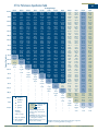
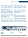
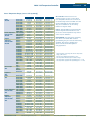
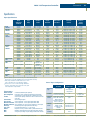
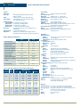
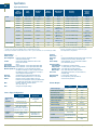
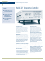
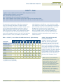
1
3 A Message from the CEO Welcome to the new Temperature Measurement and Control Catalog from Lake Shore Cryotronics. This catalog features technical data, performance characteristics, product descriptions, and a comprehensive reference section. It is designed to assist you, our valued customer, in finding the most appropriate solution to your specific cryogenic applications. As you browse through our catalog, I invite you to spend some time with the “New Products” and “Specialty Catalogs” sections. You will see the results of our commitment to provide innovative cryogenic and magnetic sensors and instruments. Featured products include silicon diode and low temperature Cernox™ sensors, temperature controllers, an AC resistance bridge, and a superconducting magnet power supply. To make it easier for you to work with us, we provide detailed technical information in our catalog and on our website. For a more in-depth discussion about your needs, Lake Shore stands ready with a trained international distribution network staffed with knowledgeable engineers and scientists. For over 35 years Lake Shore has served the international research community whose application needs require high performance measurement and control of cryogenic temperatures. We are committed to our ISO 9001 quality system, along with our large, ongoing investment in new product development. With these enrichments in personnel and technology, we strive to remain the premier cryogenics manufacturer. Thanks to your support and dedication, 2003 was a very successful year. We look forward to building on this foundation by continuously making significant improvements and developing products that you, our customer, value. Michael S. Swartz CEO www.lakeshore.com Lake Shore Cryotronics, Inc. (614) 891-2244 fax: (614) 818-1600 e-mail: [email protected] 4 © 2004 Lake Shore Cryotronics, Inc. All rights reserved. The technical and pricing information contained herein is subject to change at any time. CalCurve, SoftCal, Duo-Twist, Quad-Twist, Quad-Lead, Cernox, and Rox are all trademarks of Lake Shore Cryotronics, Inc. American Express and the American Express Box Logo are registered trademarks of American Express Company; Apiezon is a registered trademark of M & I Materials, Ltd.; CryoCable is a trademark of Omega Engineering, Inc.; Dacron, Kapton, Mylar, Teflon, and Vespel are registered trademarks of E. I. Du Pont de Nemours & Co.; Evanohm is a registered trademark of Carpenter Technology Corp.; Fair-Rite is a registered trademark of Fair-Rite Products Corp.; Gel-Pak is a registered trademark of GEL-PAK, LLC; Kester is a registered trademark of Litton Systems, Inc.; Kynar is a registered trademark of Atochem North America, Inc.; LabVIEW is a trademark of National Instruments Corporation; Lemo is a registered trademark of Lemo USA, Inc.; MasterCard and the Distinctive Interlocking Circles Design are registered trademarks of MasterCard International Incorporated; Ostalloy is a registered trademark of Umicore; Pyrex is a registered trademark of Corning Incorporated; Scotch is a registered trademark of 3M Company; Stay-Silv is a registered trademark of J.W. Harris Co., Inc.; Stycast is a registered trademark of Emerson & Cuming; Swagelok is a registered trademark of Swagelok Company; UL is a registered trademark of Underwriters Laboratories Inc.; Visa and the Visa Comet Design Mark are registered trademarks of Visa. All other trademarks or service marks noted herein are either property of Lake Shore Cryotronics, Inc., or their respective companies. www.lakeshore.com Lake Shore Cryotronics, Inc. (614) 891-2244 fax: (614) 818-1600 e-mail: [email protected] 5 Contents Introduction 6 Company Overview 8 The Lake Shore Website 10 New Products 14 18 24 29 32 36 40 43 47 50 54 58 61 64 66 67 72 77 86 94 100 106 110 114 118 124 127 Sensors Sensor Selection Guide Sensor Characteristics Sensor Packages and Mounting Adapters Temperature Probe Selection Guide DT-670 Silicon Diodes DT-400 Series Silicon Diodes GaAlAs Diodes Cernox™ RTDs Carbon-Glass RTDs Germanium RTDs Ruthenium Oxide (Rox™) RTDs PT-100 Series Platinum RTDs Rhodium-Iron RTDs Capacitance Temperature Sensors Thermocouple Wire Cryogenic Hall Generators and Probes Accessories 134 135 139 142 145 146 147 148 Cryogenic Accessories Wire Cable Solder Epoxy Grease Varnish Miscellaneous Accessories 154 156 166 179 188 197 200 207 210 216 Appendix A : Overview of Thermometry Appendix B : Sensor Characteristics Appendix C : Sensor Packaging and Installation Appendix D : Sensor Calibration Accuracies Appendix E : Temperature Measurement System Appendix F : PID Temperature Control Appendix G : Sensor Temperature Response Data Tables Appendix H : Common Units and Conversions Appendix I : Cryogenic Reference Tables Appendix J : Application Notes and Sensor Installation Instructions 222 224 225 228 Ordering Information Lake Shore Limited Warranty Sales Offices Magnetic and Electronic Specialty Catalogs Appendices Instruments Instrument Selection Guide Model 370 AC Resistance Bridge Model 340 Temperature Controller Model 332 Temperature Controller Model 331 Temperature Controller Model 321 Temperature Controller Model 218 Temperature Monitor Model 211 Temperature Monitor 230 Series Temperature Transmitters/Monitors 100 Series Current Sources Model 625 Superconducting Magnet Power Supply www.lakeshore.com Lake Shore Cryotronics, Inc. Customer Service Index 230 Index (614) 891-2244 fax: (614) 818-1600 e-mail: [email protected] 6 Introduction Company Overview Lake Shore Cryotronics, Inc. Company Overview 35 Years of Cryogenic Excellence Founded in 1967 by Dr. John Swartz, a former professor of electrical engineering at Ohio State University, and his brother David, Lake Shore Cryotronics was incorporated in the State of New York in 1968. Their first product was the Gallium-Arsenide (GaAs) sensor, being the first cryogenic sensor available commercially to cover the temperature range from 1 K to 400 K. Since that time, Lake Shore has grown steadily by concentrating on serving the needs of the scientific research community using and investigating the physical properties of materials at cryogenic temperatures. The product line expanded during the 1970’s and 1980’s to include a complete line of cryogenic temperature sensors, plus various current sources, temperature monitors, transmitters, and controllers. As the studies of magnetic properties became more relevant in material research applications, the product line expanded again in the 1990’s with the introduction of systems and instrumentation for the magnetic community. These products included magnet power supplies for electromagnets and superconducting magnets, susceptometer/ magnetometer and vibrating sample magnetometer systems, electromagnet systems, gaussmeters, Hall probes, and Hall generators. Here in the new millennium, Lake Shore continues to improve its product lines with a new fluxmeter, AC resistance bridge, digital signal processor (DSP) gaussmeter, linear magnet power supply, and Hall measurement system. Lake Shore serves a worldwide network of customers including university and national laboratories, aerospace and other industries, as well as many of the premier companies around the world. Lake Shore physicists, material scientists, and engineers continue to dedicate themselves to the development of tomorrow’s technology today. Committed to customer satisfaction and continuous improvement, Lake Shore first received ISO 9001:1994 Certification in 1998 and obtained ISO 9001:2000 Certification in 2003. One recent tribute to the Lake Shore vision is found in the latest McGraw-Hill Dictionary of Scientific and Technical Terms (Fifth Edition), where “cryotronics” is defined as “The branch of electronics that deals with the design, construction, and use of cryogenic devices.” David Swartz first coined this term in 1968 when he and his brother John named their new company Lake Shore Cryotronics. The growth of the company has mirrored the acceptance of the concept of cryogenic electronics. www.lakeshore.com Lake Shore Cryotronics, Inc. (614) 891-2244 fax: (614) 818-1600 e-mail: [email protected] Company Overview Introduction 7 Lake Shore Quality Policy Certificate number: 34093 Quality is the heart of our business and key to our goal of total customer satisfaction. Therefore, it is our policy to: Consistently provide valued products and services that meet the current and future needs of our customers and suppliers; Support each other in the daily use of quality systems, processes and methods to improve every activity constantly and forever; Continuously look for means to construct change which provides for significant improvements in quality beyond what can be achieved by continuous improvement methods alone. Dr. John M. Swartz Company Founder, Chairman of the Board www.lakeshore.com Lake Shore Cryotronics, Inc. (614) 891-2244 fax: (614) 818-1600 e-mail: [email protected] 8 The Lake Shore Website Introduction The Lake Shore Website What’s New New Products Corporate ISO 9001 Certification Company Background Career Opportunities Site Map Technical Information Technical Specifications Data Sheets Application Notes White Papers Manuals www.lakeshore.com Lake Shore Cryotronics, Inc. (614) 891-2244 fax: (614) 818-1600 e-mail: [email protected] The Lake Shore Website Introduction 9 Online Forms Request a Quote Request a Catalog Product Registration Repair Request Worldwide Sales Representative Directory ...and much more, just visit www.lakeshore.com www.lakeshore.com Lake Shore Cryotronics, Inc. (614) 891-2244 fax: (614) 818-1600 e-mail: [email protected] 10 Introduction New Products New Products DT-670 Silicon Diode Lake Shore DT-670 diode temperature sensors are the most advanced silicon diodes in our extensive line of cryogenic temperature sensors. Compared to the DT-470 and other diode thermometers, the DT-670 series offers significant improvements. The DT-670 has better tolerance bands over a wider range of temperature, a tight tolerance band specially designed for applications greater than 25 K, and is also available as a bare die that has the fastest thermal response time and smallest size of any diode temperature sensor. The DT-670 is available in the robust Lake Shore SD package, giving researchers more flexibility in sensor mounting. The DT-670 is ideal for general-purpose cryogenic thermometry across a wide range of applications. CX-1010 Cernox™ RTD The CX-1010 is the first Cernox™ designed to operate down to 100 mK, making it an ideal replacement for Germanium RTDs. Unlike Germanium, all Cernox models have the added advantage of being usable to room temperature with good sensitivity over the whole temperature range. In addition, Cernox can be purchased in the incredibly robust Lake Shore SD package, offering researchers more flexibility in sensor mounting. Model 370 AC Resistance Bridge The Model 370 is designed for precise, accurate, low noise, low excitation power AC resistance measurement. Its primary application is the measurement of resistance materials in cryogenic environments from 20 mK to 1 K. Fully integrated, the Model 370 includes features to reduce and control noise at every step of the resistance measurement process. A unique, patented, matched impedance current source and active common mode reduction circuitry minimize noise and self-heating errors. With sixteen channels, IEEE-488 and RS-232C interfaces, and closed loop temperature control, the Model 370 offers seamless integration with existing cryogenic systems and is the most complete package on the market today. Used with Lake Shore calibrated subkelvin resistance temperature sensors, the Model 370 not only measures and displays but also controls temperature for dilution refrigerators and other cryogenic systems. Model 332 Temperature Controller Designed to support the Cernox™ RTD over a greater portion of its useful temperature range, the Model 332 automatically scales excitation current for resistance temperature sensors. Excitation currents of 1 µA, 10 µA, 100 µA, and 1 mA are available. Scalable excitation current allows the Model 332 to support Cernox and other negative temperature coefficient (NTC) RTDs in temperature measurement and control applications to temperatures as low as 1 K. The Model 332 includes a 50 W heater output on the first control loop and 10 W on the second for greater flexibility in applications that require a second heater. The Model 332 supports diodes, RTDs, and thermocouples, and includes current reversal for NTC and PTC (positive temperature coefficient) RTDs. Autotuning PID control, IEEE-488 and RS-232C interfaces, alarms, relays, and analog voltage output are all standard with the Model 332. www.lakeshore.com Lake Shore Cryotronics, Inc. (614) 891-2244 fax: (614) 818-1600 e-mail: [email protected] New Products Introduction 11 New Products Model 331 Temperature Controller The Model 331 offers high performance and easy integration for benchtop and systems applications from 1.4 K to over 1000 K. The Model 331 has two sensor inputs and supports diodes, NTC RTDs, PTC RTDs, and thermocouple sensors. The Model 331 is available in two versions, the Model 331S and Model 331E. The Model 331S has two PID control loops with heater outputs of 50 W and 1 W. The Model 331S also includes RS-232C and IEEE-488 interfaces and relays. The Model 331E has one PID control loop with 50 W heater output and an RS-232C interface. Model 211 Temperature Monitor The Model 211 provides the accuracy, resolution, and interface features of a benchtop instrument in an easy to use, compact instrument. The Model 211 supports diodes, NTC RTDs, and PTC RTDs, and with the appropriate sensor the Model 211 measures from 1.4 K to 800 K. Temperature measurements are available in K, °C, °F, V, and Ω. Alarms, relays, user configurable analog voltage or current output, and a serial interface are included. The Model 211 along with the Model 218 8-channel Temperature Monitor replace Lake Shore Models 200, 201, 208, 818, and 819. Model 625 Superconducting Magnet Power Supply The Model 625 offers a linear, rather than a switch-mode output stage to minimize noise and ripple. The Model 625 can deliver up to 60 A at a compliance voltage of 5 V with the supply acting as either a source or a sink (true 4-quadrant operation). Two units can be paralleled for 120 A/5 V operation. The Model 625 incorporates a 20-bit D/A converter for internal current settings, providing a resolution of 0.1 mA. The settings can be made through the keypad, computer interface, or external analog input. The internal current ramp offers ramp rates from 0.1 mA/s to 99.999 A/s (compliance limited). The integrated persistent switch heater output is programmable to supply from 10 mA to 125 mA. Other standard features include IEEE-488 and RS-232C interfaces, analog monitor outputs, and protection during line loss or magnet quench. Obsolete Products and Their Recommended Replacements Obsolete Product Replacement Model 330 Temperature Controller Model 200 Temperature Monitor Model 201 Temperature Monitor Model 818 Temperature Monitor Model 819 Temperature Monitor Model 208 Temperature Monitor Model 620 Superconducting Magnet Power Supply CS-401 Capacitance Sensor Thermox™ TX RTD Model 241 Liquid Level Monitor Liquid Helium Level Sensors www.lakeshore.com Lake Shore Cryotronics, Inc. (614) 891-2244 Model 332 Temperature Controller Model 331S Temperature Controller Model 331E Temperature Controller Model 211 Temperature Monitor Model 218 Temperature Monitor Model 625 Superconducting Magnet Power Supply CS-501 Capacitance Sensor DT-670, Platinum RTD — — fax: (614) 818-1600 e-mail: [email protected] 12 Locate, Download, and Order from www.lakeshore.com Locate ...product and support information quickly with helpful dropdown menus and improved web pages – easily access application notes, product overviews, technical details, manuals, software, news releases, product registration, and so much more. Get local dealer and representative listings, customer support, and repair services all in one comprehensive site. Download ...helpful application notes, installation instructions, specifications, curve loading software, and manuals. Order ...Lake Shore temperature controllers, temperature monitors, temperature sensors, temperature transmitters, AC resistance bridge, current sources, cryogenic accessories, power supplies, gaussmeters, fluxmeters, Hall Effect sensors and probes all in a few easy clicks – fast and convenient! www.lakeshore.com Lake Shore Cryotronics, Inc. (614) 891-2244 fax: (614) 818-1600 e-mail: [email protected] 13 Sensors 14 18 24 29 32 36 40 43 47 50 54 58 61 64 66 67 Sensor Selection Guide Sensor Characteristics Sensor Packages and Mounting Adapters Temperature Probe Selection Guide DT-670 Silicon Diodes DT-400 Series Silicon Diodes GaAlAs Diodes Cernox™ RTDs Carbon-Glass RTDs Germanium RTDs Ruthenium Oxide (Rox™) RTDs PT-100 Series Platinum RTDs Rhodium-Iron RTDs Capacitance Temperature Sensors Thermocouple Wire Cryogenic Hall Generators and Probes 14 Sensor Selection Guide Sensors Sensor Selection Guide How to Select a Temperature Sensor for Your Application Lake Shore offers the most comprehensive line of cryogenic temperature sensors in the world. We understand that selecting a sensor is a difficult procedure. This catalog will assist you in selecting the most appropriate sensor for your application. The table on the opposite page is designed to compare the sensor characteristics more easily. Any one or several of the following environmental factors may be important to you in selecting a sensor: You will find that our sales staff will ask you many questions regarding your application. We ask a lot of questions to inform, educate, and to assist you in selecting the correct sensor. We are here to answer your questions and concerns. If you have any specific needs, please let us know. Robustness Temperature range Package size Fast thermal response time Fast electrical response time Heat sinking Small thermal mass Compatibility with harsh environments • magnetic fields • ionizing radiation • ultra high vacuum (UHV) • vibration/mechanical shock • thermal shock • temperatures above 323 K Easily measured signal Compatibility with sources of error • thermal EMFs • self-heating • noise pickup High sensitivity High accuracy* High repeatability – long and short term Unfortunately, you can’t have it all in one sensor. The most stable and accurate temperature sensors are very large, have slow response times and are extremely fragile. The sensors with the highest sensitivity and resolution have the smallest range. Choosing the appropriate sensor for a particular application necessitates prioritizing the requirements for that application. The sensors described in this catalog are manufactured for the rigors of cryogenic environments, and are designed with specific applications in mind. For much of its 35 year history, Lake Shore has focused on cryogenic sensors used for the precise measurement of temperatures from near absolute zero to well above room temperature. As you continue through the Sensor section of the catalog, you will notice that information is presented in both graphical format as well as in more detailed specifications, pertaining to topics such as the sensor’s highlights, typical magnetic field-dependent data, resistance, and sensitivity values. Characteristics such as packaging are incorporated into each sensor’s design with the customer in mind. To learn more about what package would be best for your application, please refer to the Sensor Packages and Mounting Adapters section. For more detailed information, see Appendix C. Low power dissipation Interchangeability Ease of use Low cost Available accessories Available instrumentation * The use of the terms accuracy and uncertainty throughout this catalog are used in the more general and conventional sense as opposed to following the strict metrological definitions. For more information, see Appendix B: Accuracy versus Uncertainty. www.lakeshore.com Lake Shore Cryotronics, Inc. (614) 891-2244 fax: (614) 818-1600 e-mail: [email protected] Sensor Selection Guide 15 Sensor Types Sensor Overview Temperature range Standard curve Silicon 1.4 K to 500 K × GaAlAs 1.4 K to 500 K Below 1K Can be used in radiation Performance in magnetic field Diodes Fair above 60 K Fair Positive Temperature Coefficient RTDs Platinum Rhodium-Iron Sensors 14 K to 873 K × × Fair above 30 K 0.65 K to 500 K × × Fair above 77 K Cernox™ 0.10 K to 325 K × × Excellent above 1 K Cernox™ HT 0.30 K to 420 K × × Excellent above 1 K Germanium 0.05 K to 100 K × × Not recommended Carbon-Glass 1.4 K to 325 K Ruthenium Oxide* 0.01 K to 40 K × Thermocouples 1.2 K to 1543 K × Capacitance 1.4 K to 290 K Negative Temperature Coefficient RTDs × × Good × Good below 1 K Other Fair Excellent *RX-102B not recommended for use in magnetic fields Silicon Diodes Silicon Diodes are the best choice for general-purpose cryogenic use. The sensors are interchangeable (they follow a standard curve) and are available in robust mounting packages and probes. Silicon Diodes are easy and inexpensive to instrument, and are used in a wide variety of cryogenic applications, such as cryo-coolers, laboratory cryogenics, cryo-gas production, and space satellites. Cernox™ Cernox™ sensors can be used from 100 mK to 420 K with good sensitivity over the whole range. They have a low magnetoresistance, and are the best choice for applications with magnetic fields up to 30 T (for temperatures greater than 2 K). Cernox™ are resistant to ionizing radiation, and are available in robust mounting packages and probes. Because of their versatility, they are used in a wide variety of cryogenic applications, such as particle accelerators, space satellites, MRI systems, cryogenic systems, and research science. Platinum Platinum RTDs are an industry standard. They follow an industry standard curve from 73 K to 873 K with good sensitivity over the whole range. Platinum RTDs can also be used down to 14 K. Because of their high reproducibility, they are used in many precision metrology applications. Platinum RTDs have limited packaging options, but they are inexpensive and require simple instrumentation. They are widely used in cryogenic applications at liquid nitrogen temperatures or greater. www.lakeshore.com Lake Shore Cryotronics, Inc. (614) 891-2244 fax: (614) 818-1600 e-mail: [email protected] 16 Sensor Selection Guide Sensors Sensor Types, continued Germanium Germanium RTDs have the highest accuracy, reproducibility, and sensitivity from 0.05 K to 30 K (some models useful up to 100 K). They are resistant to ionizing radiation, but are not recommended for use in magnetic fields. Germanium RTDs are used mostly in research settings when the best accuracy and sensitivity are required. Germanium and Ruthenium Oxide are the only two sensors that can be used below 100 mK. Ruthenium Oxide (Rox™) Ruthenium Oxide RTDs can be used to below 10 mK. Their unique advantage is that they have a low magnetoresistance and follow a standard curve (with the exception of the RX-102B). Their upper temperature range is limited to 40 K, and Cernox™ are better in magnetic fields above 2 K. Ruthenium Oxide sensors are often used for applications that require a standard curve in magnetic fields, such as MRI systems. Along with Germanium, they are the only sensors that can be used below 100 mK. GaAlAs Diodes GaAlAs Diodes offer high sensitivity over a wide range of use (1.4 K to 500 K). They are useful in moderate magnetic fields, and offer many of the advantages of Silicon Diodes—easy to instrument, wide range, and robust packaging. They do not follow a standard curve. GaAlAs diodes are used in moderate magnetic field applications when instrumentation constraints (e.g., legacy installations, cost) prevent the use of Cernox™. www.lakeshore.com Rhodium-Iron Rhodium-Iron temperature sensors can be used over a wide temperature range, and are resistant to ionizing radiation. Wirewound capsule versions (RF-800) have excellent stability and are widely used as secondary temperature standards by many national standards laboratories. Thin-film Rhodium-Iron sensors have various packaging options, including the SD package and bare chip. They require similar instrumentation as a Platinum RTD, and are used in applications when packaging, size, and temperature range prevent the use of Platinum or Cernox™ sensors. Carbon-Glass Carbon-Glass resistance temperature sensors are highly sensitive and reproducible and can be used from 1.4 K to 100 K in magnetic fields up to 20 T. The magnetoresistance of Carbon-Glass is less than Cernox™. Physical construction of the CGR also limits the number of packaging options. For most cryogenic applications requiring high sensitivity in magnetic fields, Lake Shore recommends the Cernox™ sensor. Lake Shore Cryotronics, Inc. (614) 891-2244 Thermocouples Thermocouples can be used over an extremely wide range and in harsh environmental conditions, and follow a standard response curve. Less accurate than other sensors, special techniques must be employed when using thermocouples to approach temperature accuracies of 1% of temperature. Thermocouples are used for their small size, extremely wide temperature range (exceeding high temperature limits of Platinum RTDs), and simple temperature measurement methodology. Capacitance Capacitance sensors are ideally suited for use as temperature control sensors in strong magnetic fields because they exhibit virtually no magnetic field dependence. Small variations in the capacitance/temperature curves occur upon thermal cycling. It is recommended that temperature in zero field be measured with another temperature sensor, and that the capacitance sensor be employed as a control element only. fax: (614) 818-1600 e-mail: [email protected] Sensor Selection Guide Sensors 17 Lake Shore Calibrations Lake Shore offers complete calibration services from 50 mK to 800 K. Above 0.65 K, Lake Shore calibrations are based on the International Temperature Scale of 1990 (ITS-90). For temperature below 0.65 K, calibrations are based on the Provisional Low Temperature Scale of 2000 (PLT-2000). Each scale is maintained on a set of germanium, rhodium-iron, and/or platinum resistance secondary thermometers standards. These secondary standards are calibrated at various national labs: NIST, PTB, and NPL. Working thermometers are calibrated against, and routinely intercompared with these secondary standards. For PLTS-2000 calibrations, working sensors are also compared to a superconducting fixed-point set and nuclear orientation thermometer. Lake Shore will soon be offering sensor calibrations down to 20 mK. We have enhanced our ultra-low temperature calibration facility to include a new dilution refrigerator, nuclear orientation thermometer, and superconducting fixed point set. Look for new product announcements later this year. All calibration reports include: Certificate of calibration Calibration test data and data plot Polynomial fit equations and fit comparisons Interpolation tables Instrument breakpoint tables and data files Lake Shore offers three classifications of calibration: Good Uncalibrated Better SoftCal™ An abbreviated calibration (2-point: 77 K and 305 K; 3-point: 4.2 K, 77 K, and 305 K; or 3-point: 77 K, 305 K, and 480 K) which is available for 400 Series silicon diodes and platinum sensors Best Calibration All sensors can be calibrated in the various temperature ranges. Lake Shore has defined calibration ranges available for each sensor type. The digits represent the lower range in kelvin, and the letter corresponds to high temperature limit, where: Silicon diodes follow standard curve Platinum resistors follow standard curve Ruthenium oxide (Rox™) resistors follow standard curve (except RX-102B) GaAlAs diode, carbon-glass, Cernox™, germanium, Rox™ RX-102B, and rhodium-iron sensors can be purchased uncalibrated but must be calibrated by the customer A=6K www.lakeshore.com B = 40 K D = 100 K Lake Shore Cryotronics, Inc. L = 325 K M = 420 K (614) 891-2244 H = 500 K J = 800 K fax: (614) 818-1600 e-mail: [email protected] 18 Sensor Characteristics Sensor Packages and Characteristics Thermo- Capaci- Rhodium Platinum couples tance Iron Rox™ Germanium CarbonGlass Cernox™ GaAlAs Diodes Silicon Diodes Sensor type/ packages 1 DT-670-SD DT-670E-BR DT-414 DT-421 DT-470-SD DT-471-SD TG-120-P TG-120-PL TG-120-SD CX-1010-BC CX-1010-SD CX-1010-AA CX-1030-BC CX-1030-SD-HT CX-1030-AA CX-1050-BC CX-1050-SD-HT CX-1050-AA CX-1070-BC CX-1070-SD-HT CX-1070-AA CX-1080-BC CX-1080-SD-HT CX-1080-AA CGR-1-500 CGR-1-1000 CGR-1-2000 GR-200A-30 GR-200A-50 GR-200A-100 GR-200A-250 GR-200A-500 GR-200A-1000 GR-200A-1500 GR-200A-2500 GR-200B-500 GR-200B-1000 GR-200B-1500 GR-200B-2500 RX-102A-BR RX-102A-AA RX-102B-CB RX-202A-AA RX-103A-BR RX-103A-AA PT-102 PT-103 PT-111 RF-100-BC RF-100-AA RF-800-40.65 K CS-501-GR Temperature range low high 1.4 K 500 K 30 K 500 K 1.4 K 375 K 1.4 K 325 K 1.4 K 500 K 10 K 500 K 1.4 K 325 K 1.4 K 325 K 1.4 K 500 K 0.1 K 325 K 0.1 K 325 K 0.1 K 325 K 0.30 K 325 K 0.30 K 420 K 0.30 K 325 K 1.4 K 325 K 1.4 K 420 K 1.4 K 325 K 4.2 K 325 K 4.2 K 420 K 4.2 K 325 K 20 K 325 K 20 K 420 K 20 K 325 K 1.4 K 325 K 1.4 K 325 K 1.4 K 325 K 0.05 K 4.2 K 0.1 K 40 K 0.3 K 40 K 0.5 K 100 K 1.4 K 100 K 1.4 K 100 K 1.4 K 100 K 1.4 K 100 K 1.4 K 100 K 1.4 K 100 K 1.4 K 100 K 1.4 K 100 K 0.05 K 40 K 0.05 K 40 K 0.01 K 40 K 0.05 K 40 K 1.4 K 40 K 1.4 K 40 K 14 K 873 K 14 K 873 K 14 K 673 K 1.4 K 325 K 1.4 K 325 K 800 K 1.4 K 290 K Type K 3.2 K Type E 3.2 K Chromel-AuFe (0.07%) 1.2 K 1543 K 953 K 610 K Physical size1 Mass 1.08 mm high × 1.905 mm wide × 3.175 mm long 0.178 mm × 0.432 mm × 0.406 mm 0.5 mm high × 0.635 mm × 1.524 mm long 0.762 mm high × 1.27 mm dia. 1.08 mm high × 1.905 mm wide × 3.175 mm long 1.08 mm high × 1.905 mm wide × 3.175 mm long 2.794 mm long × 3.048 mm dia. 1.335±0.3175 mm long × 1.333±0.3175 mm thick 1.08 mm high × 1.905 mm wide × 3.175 mm long 0.152 ±0.025 mm × 0.940 mm × 1.143 mm 1.08 mm high × 1.905 mm wide × 3.175 mm long 3.048 mm dia. × 8.509 mm long 0.152 ±0.025 mm × 0.940 mm × 1.143 mm 1.08 mm high × 1.905 mm wide × 3.175 mm long 3.048 mm dia. × 8.509 mm long 0.152 ±0.025 mm × 0.940 mm × 1.143 mm 1.08 mm high × 1.905 mm wide × 3.175 mm long 3.048 mm dia. × 8.509 mm long 0.152 ±0.025 mm × 0.940 mm × 1.143 mm 1.08 mm high × 1.905 mm wide × 3.175 mm long 3.048 mm dia. × 8.509 mm long 0.152 ±0.025 mm × 0.940 mm × 1.143 mm 1.08 mm high × 1.905 mm wide × 3.175 mm long 3.048 mm dia. × 8.509 mm long 3.048 mm dia. × 8.509 mm long 3.048 mm dia. × 8.509 mm long 3.048 mm dia. × 8.509 mm long 3.048 mm dia. × 8.509 mm long 3.048 mm dia. × 8.509 mm long 3.048 mm dia. × 8.509 mm long 3.048 mm dia. × 8.509 mm long 3.048 mm dia. × 8.509 mm long 3.048 mm dia. × 8.509 mm long 3.048 mm dia. × 8.509 mm long 3.048 mm dia. × 8.509 mm long 2.261 mm dia. × 6.096 mm long 2.261 mm dia. × 6.096 mm long 2.261 mm dia. × 6.096 mm long 2.261 mm dia. × 6.096 mm long 1.45 mm × 1.27 mm × 0.65 mm thick 3.048 mm dia. × 8.509 mm long 14.605 mm high × 6.35 mm wide × 6.35 mm long 3.048 mm dia. × 8.509 mm long 1.40 mm × 1.23 mm × 0.41 mm thick 3.048 mm dia. × 8.509 mm long 2.007 mm dia. × 20.995 mm long 1.6 mm dia. × 12.192 mm long 1.8 mm dia. × 5 mm long 1.3 mm wide × 3.8 mm long × 0.38 mm 3.048 mm dia. × 8.509 mm long 3.175 mm dia. × 20.32 mm long 3.048 mm dia. × 8. 484 mm long 37 mg 72.7 µg 3 mg 23 mg 37 mg 37 mg 79 mg 20 mg 38 mg 3.0 mg 40 mg 400 mg 3.0 mg 40 mg 400 mg 3.0 mg 40 mg 400 mg 3.0 mg 40 mg 400 mg 3.0 mg 40 mg 400 mg 330 mg 330 mg 330 mg 355 mg 355 mg 355 mg 355 mg 355 mg 355 mg 355 mg 355 mg 205 mg 205 mg 205 mg 205 mg 2.8 mg 350 mg 3.5 g 350 mg 3.7 mg 350 mg 250 mg 120 mg 52 mg 7 mg 360 mg 735 mg 260 mg 1.4 K -0.01 -0.01 -0.01 -0.01 -0.01 — -0.03 -0.03 -0.03 -0.68 — — -1.15 — — -2.5 — — — — — — — — -6.9 -7.8 -8.4 -0.76 -0.93 -1.8 -2.3 -3.3 -3.6 -3.5 -3.9 -3.3 -3.6 -3.5 -3.9 -0.47 -0.47 -0.16 -0.34 -0.62 -0.62 — — — +0.10 +0.10 +0.16 +0.01 Typical Dimensionless Sensitivity SD for definition of Sd 4.2 K 20 K 77.4 K 295 K -0.08 -0.26 -0.13 -1.19 -0.08 -0.26 -0.13 -1.19 -0.09 -0.29 -0.15 -1.3 -0.09 -0.29 -0.15 -1.3 -0.09 -0.20 -0.15 -1.3 — -0.29 -0.15 -1.3 -0.19 -0.77 -0.07 -0.9 -0.19 -0.77 -0.07 -0.9 -0.19 -0.77 -0.07 -0.9 -0.49 -0.44 -0.56 -0.65 — — — — — — — — -0.71 -0.56 -0.63 -0.64 — — — — — — — — -1.3 -0.9 -0.91 -0.87 — — — — — — — — -1.5 -1 -1 -0.9 — — — — — — — — — -1.5 -1.4 -1.2 — — — — — — — — -3.1 -0.98 -0.48 -0.33 -3.5 -1.1 -0.53 -0.35 -3.8 -1.2 -0.56 -0.37 -0.32 — — — -0.73 -0.62 — — -1.2 -1.0 — — -1.6 -1.2 -1.1 — -1.9 -2.0 -1.1 — -2.1 -2.1 -1.2 — -2.1 -2.0 -1.2 — -2.6 -2.4 -0.97 — -1.9 -2.0 -1.1 — -2.1 -2.1 -1.2 — -2.0 -2.0 -1.2 — -2.6 -2.4 -0.97 — -0.25 -0.07 — — -0.25 -0.07 — — -0.11 -0.12 — — -0.17 -0.10 — — -0.36 -0.17 — — -0.36 -0.17 — — — +0.74 +1.6 +1.1 — +0.74 +1.6 +1.1 — +0.74 +1.6 +1.1 +0.21 +0.23 +1.1 +1.0 +0.21 +0.23 +1.1 +1.0 +0.29 +0.29 +1.1 +1.0 +0.02 +0.11 +0.46 -4.4 30 AWG (0.254 mm) & 36 AWG (0.127 mm) 30 AWG (0.254 mm) & 36 AWG (0.127 mm) 30 AWG (0.254 mm) & 36 AWG (0.127 mm) 475 K -7.5 — — — -11.6 -11.6 -4.0 -4.0 -4.0 — — — — — — — — — — — — — — — — — — — — — — — — — — — — — — — — — — — — +1.0 +1.0 +1.0 — — — — NA Adapters will increase thermal response times – see individual sensor specifications for thermal response times www.lakeshore.com Lake Shore Cryotronics, Inc. (614) 891-2244 fax: (614) 818-1600 e-mail: [email protected] Sensor Package Size versus Temperature Sensor Characteristics Largest 0.01 0.03 0.05 0.1 0.3 Large Packages ( >400 mg) 1 1.4 3 4.2 Rhodium-Iron Copper Can Packages1 (250 – 400 mg) 10 30 77 100 300 325 500 800 1000 1550 K 500 800 1000 1550 K RF-800-4 CX-1010-AA CX-1030-AA CX-1050-AA Cernox™ CX-1070-AA CX-1080-AA CGR-1-500 Carbon-Glass CGR-1-1000 CGR-1-2000 RX-102A-AA, RX-202A-AA Rox™ RX-103A-AA GR-200A-30 GR-200A-50 GR-200A-100 Germanium GR-200A-250 GR-200A-500/1000/1500/2500 Rhodium-Iron RF-100T/U-AA Chromel AuFe (0.07%) Miscellaneous Packages (50 mg – 3.5 g) Thermocouples Type E Sensor Package Size Type K RX-102B-CB Rox™ GaAlAs Diodes TG-120-P GR-200B-500/1000/1500/2500 Germanium PT-102, PT-103 Platinum PT-111 Capacitors Hermetically Sealed Packages2 (37 – 40 mg) CS-501-GR DT-670-SD Silicon Diodes DT-470-SD (some adapters limit sensor to 400 K) DT-471-SD (some adapters limit sensor to 400 K) GaAlAs Diodes TG-120-SD CX-1010-SD CX-1030-SD-HT CX-1050-SD-HT Cernox™ CX-1070-SD-HT CX-1080-SD-HT Miniature Packages (10 – 30 mg) DT-414 Silicon Diodes DT-421 GaAlAs Diodes Bare Chip Sensors (<10 mg) (-BC, BG, BR, BM, MG, MC) TG-120-PL RX-102A-BR Rox™ RX-103A-BR CX-1010-BC/BG/BR CX-1030-BC/BG/BR Cernox™ CX-1050-BC/BG/BR CX-1070-BC/BG/BR Smallest CX-1080-BC/BG/BR Rhodium-Iron RF-100-BC DT-670E-BR Silicon Diodes 0.01 0.03 0.05 0.1 0.3 1 1.4 3 4.2 10 30 77 100 300 325 Not recommended for use in magnetic field (darker shaded area refers to reduced sensitivity) Recommended for use in magnetic field (darker shaded area refers to reduced sensitivity) 2 www.lakeshore.com Adapters will increase thermal mass Lake Shore Cryotronics, Inc. (614) 891-2244 fax: (614) 818-1600 e-mail: [email protected] 20 Sensor Characteristics Sensors Short and Long Term Sensor Characteristics Interchangeability Typical Reproducibility at 4.2 K Typical Long-term Stability Silicon Diode Yes – see page 22 ±10 mK GaAlAs Diode No ±10 mK Cernox™ No ±3 mK Carbon-Glass No ±0.75 mK Germanium No ±0.5 mK Yes3 Yes – see page 22 ±15 mK ±5 mK4 4.2 K: ±10 mK/yr 77 K: ±40 mK/yr 300 K: ±25 mK/yr 4.2 K: ±15 mK/yr 77 K: ±15 mK/yr 330 K: ±50 mK/yr 1 K to 100 K: ±25 mK/yr 100 K to 300 K: 0.05% of T 4.2 K: -5 mK/yr 15 K: -30 mK/yr 77 K: -100 mK/yr 300 K: -600 mK/yr 4.2 K: ±1 mK/yr 77 K: ±10 mK/yr 4.2 K: ±15 to 50 mK/yr (model dependent) 77 K to 273 K: ±10 mK/yr No No No ±10 mK ±5 mK ±0.01 K after cooling and stabilizing 1.4 K to 325 K: ±20 mK/yr 1.4 K to 325 K: ±10 mK/yr ±1.0 K/yr Yes – see ASTM standard Yes – see ASTM standard Yes – see ASTM standard Yes – see ASTM standard NA NA NA NA NA NA NA NA Rox™ Platinum Rhodium-Iron RF-100 RF-800 Capacitance Thermocouples Type K Type E Type T Chromel-AuFe (0.07%) 3 4 With the exception of the RX-102B-CB Platinum reproducibility tested at 77 K Sensor Characteristics in Various Environments Sensor Type Silicon Diode Use in Vacuum Use in Radiation5 Use in Magnetic Fields5 Not Recommended Not recommended for T<60 K, or for B>5 tesla above 60 K High 10-1 to 10-4 Pa Very High 10-4 to 10-7 Pa Ultra High 10-7 to 10-10 Pa DT-421 — Recommended GaAlAs Diode TG-120-P — Cernox™6 AA can — Carbon-Glass6 AA can — DT-670-SD DT-414 DT-470-SD DT-471-SD TG-120-SD TG-120-PL Bare Chip SD Bare Chip Germanium6 AA can B can AA can — — — — Bare Chip Recommended — PT-102 PT-103 PT-111 Bare Chip — — — Recommended Recommended Not recommended for use except at low B due to large orientation-dependent magnetic field effect Excellent for use in magnetic fields (except RX-102B) Moderately orientation dependent – suggested use only T ≥ 30 K Rhodium-Iron6 RF-100 AA can — Bare Chip Recommended Not recommended below 77 K RF-800 Capacitance — CS-501 RF-800-4 — — Not available Not recommended below 77 K Recommended for control purposes Recommended Useful when T ≥ 10 K — Rox™ Platinum Insulated wire — — Thermocouples See additional information in Appendix A: Overview of Thermometry 6 Adapters with epoxy are limited to a bakeout temperature of 127 °C SD package has magnetic leads Not Recommended Recommended Relatively low field dependence DT/T(%) ≤ 4% for B<5 tesla and T ≥ 4.2 K; SD package with non-magnetic leads Excellent for use in magnetic fields 1 K and up SD package with non-magnetic leads Useful to 300 K 5 www.lakeshore.com Lake Shore Cryotronics, Inc. (614) 891-2244 fax: (614) 818-1600 e-mail: [email protected] 21 Typical Magnetic Field-Dependent Temperature Errors, ∆T/T (%), at B (magnetic induction) Sensor type Cernox™ 1050 (CX series) Carbon-Glass Resistors (CGR series) Rox™ 102A Rox™ 102B Rox™ 103A Rox™ 202A Platinum Resistors (PT series) Rhodium-Iron (RF series) Capacitance CS-501-GR series Germanium Resistors (GR series) Chromel-AuFe (0.07%) Type E Thermocouples (Chromel-Constantan) Sensor type Silicon Diodes Junction parallel to field (DT series) Silicon Diodes Junction perpendicular to field (DT series) GaAlAs Diodes (TG series) www.lakeshore.com T(K) 2 4.2 10 20 30 77 300 4.2 10 25 45 88 306 2 3 4 8 16 23 2 3 4 8 16 23 2 3 4 8 16 23 2 3 4 8 16 23 20 40 87 300 4.2 40 87 300 Magnetic Flux Density B 8T 14 T 19 T 3.1 3.9 5 -0.15 -0.85 -0.8 -0.4 -1.1 -1.5 0.02 -0.16 -0.2 0.04 0.06 0.11 0.022 0.062 0.11 0.004 0.004 0.006 -2.3 -4.9 -6.6 -1.1 -2.6 -3.8 0.22 0.54 0.79 0.48 1.32 2.2 0.45 1.32 2.3 0.22 0.62 1.1 -7.9 -13 -17 -7 -14 -18 -6.7 -14 -18 -6.1 -13 -21 -3.4 -9.6 -16 -2.2 -6.2 -11 13.82 22.53 27.95 14.68 23.12 29.12 13.92 22.57 28.20 7.53 13.50 17.86 2.14 4.66 6.58 0.79 2.01 3.11 1.5 2.2 2.6 1.1 1.7 2.0 0.95 1.4 1.7 0.49 0.71 0.80 0.076 0.089 0.040 0.0058 -0.0060 -.0.095 -2.2 -3.9 -5.2 -0.68 -2.7 -3.7 0.046 -1.8 -3.2 0.16 -0.65 -3.0 0.16 -0.48 -1.5 -0.08 -0.39 -0.92 100 250 — 3 6 8.8 0.4 1 1.7 0.02 0.07 0.13 40 — — 12 30 47 1.5 4 6 0.1 0.4 — ∆T/T(%) < 0.015 at 4.2 K and 18.7 tesla ∆T/T(%) <0.05 at 77 K and 305 K and 18.7 tesla -60 — — -30 to -55 -60 to -75 — -25 to -60 -60 to -75 — -15 to -35 -50 to -80 — 30 — 20 5 7 — 0.8 — — 3 7 — 2 4 — <1 2 — 2.5 T 1.3 0.1 0.04 0.04 0.01 0.002 0.003 -0.5 -0.2 0.02 0.07 0.05 <0.01 -1.4 -1.5 -0.56 -1.3 -0.40 -0.31 3.29 3.96 3.53 1.53 0.27 0.06 0.58 0.44 0.27 0.11 0.018 0.0051 -0.13 0.18 0.77 -0.023 0.03 -0.05 20 0.5 0 .04 <0.01 11 1.5 0.2 <0.01 2.0 4.2 10 20 10 45 100 10 20 455 -8 -5 to -20 -4 to -15 -3 to -20 3 1 0.1 1 <1 <1 T(K) 4.2 20 40 60 80 300 4.2 20 40 60 80 300 4.2 30 78 300 1 -200 -10 -4 -0.5 <0.1 <0.1 -8 -4 -1.5 -0.5 -0.1 <0.1 2.9 0.2 <0.1 -0.1 2 -300 -20 -6 -1 -0.5 <-0.1 -9 -5 -3 -1 -0.3 0.2 3.8 0.2 <0.1 <0.1 Lake Shore Cryotronics, Inc. 3 -350 -25 -8 -2 -0.8 <-0.1 -11 -5 -4 -2 -0.5 0.5 3.7 0.3 0.17 <0.1 4 -400 -30 -10 -3 -1.1 <-0.1 -15 -5 -5 -3 -0.6 0.6 2.8 0.3 0.16 <0.1 (614) 891-2244 5 -500 -40 -12 -3.5 -1.5 <-0.1 -20 -10 -5.5 -3.5 -0.7 0.6 1 0.2 0.1 <0.1 Notes Best sensor for use in magnetic field (T > 1 K) Recommended for use over the 0.05 K to 40 K temperature range. Consistent behavior between devices in magnetic fields. Not recommended for use in magnetic fields. Excellent for use in magnetic fields from 1.4 K to 40 K. Predictable behavior. Recommended for use over the 0.05 K to 40 K temperature range. Consistent behavior between devices in magnetic fields. Recommended for use when T ≥ 40 K. Not recommended for use below 77 K in magnetic fields. Recommended for control purposes. Monotonic in C vs. T to nearly room temperature. Not recommended except at low B owing to large, orientation-dependent temperature effect. Data taken with entire thermocouple in field, cold junction at 4.2 K; errors in hot junction. Useful when T ≥ 10 K. Refer to notes for Chromel-AuFe (0.07%). Notes Strongly orientation dependent. Strongly orientation dependent. Shown with junction perpendicular (package base parallel) to applied field B. When junction is parallel to B, induced errors are typically less than or on the order of those shown. fax: (614) 818-1600 e-mail: [email protected] 22 Sensor Characteristics Sensors Typical Accuracy* (Interchangeability): Uncalibrated Sensors Temperature Model number 0.05 K 0.5 K 1.4 K 2K 4.2 K 10 K 20 K 25 K 40 K 70 K 100 K 305 K 400 K 500 K 670 K DT-470-SD, Band 11 — — — ±0.25 K ±0.25 K ±0.25 K ±0.25 K ±0.25 K ±0.25 K ±0.25 K ±0.25 K ±0.5 K ±1.0 K ±1.0 K — DT-470-SD, Band 11A — — — ±0.25 K ±0.25 K ±0.25 K ±0.25 K ±0.25 K ±0.25 K ±0.25 K ±0.25 K ±1% of temp ±1% of temp ±1% of temp — DT-470-SD, Band 12 — — — ±0.5 K ±0.5 K ±0.5 K ±0.5 K ±0.5 K ±0.5 K ±0.5 K ±0.5 K ±1.0 K ±2.0 K ±2.0 K — DT-470-SD, Band 12A — — — ±0.5 K ±0.5 K ±0.5 K ±0.5 K ±0.5 K ±0.5 K ±0.5 K ±0.5 K ±1% of temp ±1% of temp ±1% of temp — DT-470-SD, Band 13 — — — ±1.0 K ±1.0 K ±1.0 K ±1.0 K ±1.0 K ±1.0 K ±1.0 K ±1.0 K ±1% of temp ±1% of temp ±1% of temp — DT-471-SD — — — — — ±1.5 K ±1.5 K ±1.5 K ±1.5 K ±1.5 K ±1.5 K ±1.5% of temp ±1.5% of temp ±1.5% of temp — DT-414 — — — ±1.5 K ±1.5 K ±1.5 K ±1.5 K ±1.5 K ±1.5 K ±1.5 K ±1.5 K ±1.5% of temp — — — DT-421 — — — — — — ±2.5 K ±2.5 K ±2.5 K ±2.5 K ±2.5 K ±1.5% of temp — — — DT-670-SD, Band A — — — ±0.25 K ±0.25 K ±0.25 K ±0.25 K ±0.25 K ±0.25 K ±0.25 K ±0.25 K ±0.5 K ±0.5 K ±0.5 K — DT-670-SD, Band B — — — ±0.5 K ±0.5 K ±0.5 K ±0.5 K ±0.5 K ±0.5 K ±0.5 K ±0.5 K ±0.5 K ±0.33% of temp ±0.33% of temp — DT-670-SD, Band C — — — ±1.0 K ±1.0 K ±1.0 K ±1.0 K ±1.0 K ±1.0 K ±1.0 K ±1.0 K ±1.0 K ±0.5% of temp ±0.5% of temp — DT-670-SD, Band D — — — — — — — ±0.25 K ±0.25 K ±0.25 K ±0.25 K ±0.30 K ±0.1% of temp ±0.1% of temp — DT-670-SD, Band E — — — — — — — ±0.25 K ±0.25 K ±0.25 K ±0.25 K ±0.25% of temp ±0.25% of temp ±0.25% of temp — PT-102 — — — — — — — — — ±1.3 K ±1.2 K ±0.5 K ±0.9 K ±1.4 K ±2.3 K PT-103 — — — — — — — — — ±1.3 K ±1.2 K ±0.5 K ±0.9 K ±1.4 K ±2.3 K PT-111 — — — — — — — — — ±1.3 K ±1.2 K ±0.5 K ±0.9 K ±1.4 K ±2.3 K ±1.5 K ±4.0 K — — — — — — ±20 mK ±25 mK ±40 mK ±75 mK ±200 mK ±500 mK ±750 mK ±1.5 K — — — — — — Silicon Diode Platinum Rox™ RX-102A-AA ±10 mK ±25 mK ±50 mK ±75 mK ±125 mK ±300 mK ±1.25 K RX-102A-AA-M ±5 mK RX-202A-AA ±15 mK ±30 mK ±100 mK ±125 mK ±250 mK RX-202A-AA-M ±10 mK ±25 mK ±50 mK ±75 mK ±150 mK ±500 mK ±1.0 K ±1 K ±1 K ±2.5 K RX-103A-AA — — ±150 mK ±180 mK ±400 mK ±2.0 K RX-103A-AA-M — — ±50 mK ±75 mK ±100 mK ±300 mK ±700 mK ±3 K ±5.0 K — — — — — — ±1.5 K ±2.0 K — — — — — — ±2.5 K ±4.0 K — — — — — — ±1 K ±1.5 K — — — — — — Typical Accuracy*: SoftCal™ (2-Point and 3-Point Soft Calibration Temperature Model number 2K 4.2 K DT-470-SD-2S7 (Band 13) ±1.0 K DT-471-SD-2S7 (Band 13) — DT-421-2S7 (Band 13) 10 K 30 K 70 K 305 K 400 K 475 K 500 K 670 K ±1.0 K ±1.0 K ±0.25 K ±0.15 K ±0.15 K ±1.0 K ±1.0 K — — — ±1.5 K ±0.25 K ±0.15 K ±0.15 K ±1.0 K ±1.0 K — — — — ±2.0 K ±0.25 K ±0.15 K ±0.15 K — — — DT-470-SD-3S8 (Band 13) ±0.5 K ±0.5 K ±0.5 K ±0.25 K ±0.15 K ±0.15 K ±1.0 K ±1.0 K — — DT-471-SD-3S8 (Band 13) ±0.5 K ±0.5 K ±0.5 K ±0.25 K ±0.15 K ±0.15 K ±1.0 K ±1.0 K — — PT-102-2S7 — — — — ±0.25 K ±0.25 K ±0.9 K ±1.3 K ±1.4 K ±2.3 K PT-103-2S7 — — — — ±0.25 K ±0.25 K ±0.9 K ±1.3 K ±1.4 K ±2.3 K PT-111-2S7 — — — — ±0.25 K ±0.25 K ±0.9 K ±1.3 K ±1.4 K ±2.3 K PT-102-3S9 — — — — ±0.25 K ±0.25 K ±0.25 K ±0.25 K ±1.4 K ±2.3 K PT-103-3S9 — — — — ±0.25 K ±0.25 K ±0.25 K ±0.25 K ±1.4 K ±2.3 K PT-111-3S9 — — — — ±0.25 K ±0.25 K ±0.25 K ±0.25 K ±1.4 K ±2.3 K Silicon Diode — Platinum 2S (2-point at 77 K and 305 K) 8 3S (3-point at 4.2 K, 77 K, and 305 K) 9 3S (3-point at 77 K, 305 K, and 480 K) 7 www.lakeshore.com Lake Shore Cryotronics, Inc. (614) 891-2244 * The use of the terms accuracy and uncertainty throughout this catalog are used in the more general and conventional sense as opposed to following the strict metrological definitions. For more information, see Appendix B: Accuracy versus Uncertainty, page 158. fax: (614) 818-1600 e-mail: [email protected] Sensor Characteristics Typical Accuracy*: Calibrated Sensors Sensors 23 10 Temperature Model number Silicon Diode DT-670-SD/CO DT-670-CU/CO/LR/CY/ET/BO DT-414 DT-421 DT-470-SD/CO DT-470-BO/BR/CU/CY/ET/LR/MT DT-471-SD/CO DT-471-BO/BR/CU/CY/ET/LR/MT GaAlAs Diode TG-120-P TG-120-PL TG-120-SD/CO TG-120-CU Cernox™ CX-1010-AA/CD/CO/CU/LR/ET/MT/SD CX-1010-BC CX-1030-AA/CD/CO/CU/LR/ET/MT/SD CX-1030-BC CX-1050-AA/BC/CD/CO/CU/LR/ET/MT/SD CX-1070-AA/BC/CD/CO/CU/LR/ET/MT/SD CX-1080-AA/BC/CD/CO/CU/LR/ET/MT/SD CX-1030-CO/CU/SD-HT CX-1050-CO/CU/SD-HT CX-1070-CO/CU/SD-HT CX-1080-CO/CU/SD-HT Carbon-Glass CGR-1-500, CGR-1-500-CD CGR-1-1000, CGR-1-1000-CD CGR-1-2000, CGR-1-2000-CD Rox™ RX-102A-AA/CD RX-102B-CB RX-103A-AA/CD RX-202A-AA/CD Rhodium-Iron RF-100T-AA/CD/BC/MC RF-100U-AA/CD/BC RF-800-4 Platinum PT-102, PT-102-AL PT-103, PT-103-AM PT-111 Germanium GR-200A-30, GR-200A-30-CD GR-200A-50, GR-200A-50-CD GR-200A-100, GR-200A-100-CD GR-200A-250, GR-200A-250-CD GR-200A-500, GR-200A-500-CD, GR-200B-500 GR-200A-1000, GR-200A-1000-CD, GR-200B-1000 GR-200A-1500, GR-200A-1500-CD, GR-200B-1500 GR-200A-2500, GR-200A-2500-CD 0.01 K 0.02 K 0.05 K 0.1 K 0.3 K 0.5 K 1K 1.4 K 4.2 K 10 K 20 K 77 K — — — — — — — — — — — — — — — — — — — — — — — — — — — — — — — — — — — — — — — — — — — — — — — — — — — — — — — — ±12 mK ±12 mK — ±12 mK ±12 mK ±12 mK — — ±12 mK ±12 mK ±12 mK ±12 mK ±12 mK ±12 mK — — ±12 mK ±12 mK ±12 mK ±12 mK ±12 mK ±12 mK ±12 mK ±12 mK ±14 mK ±14 mK ±14 mK ±14 mK ±14 mK ±14 mK ±14 mK ±14 mK ±22 mK ±22 mK ±22 mK ±22 mK ±22 mK ±22 mK ±22 mK ±22 mK ±32 mK ±45 mK ±50 mK ±32 mK — — ±32 mK — — ±32 mK — — ±32 mK ±45 mK ±50 mK ±32 mK — — ±32 mK ±45 mK ±50 mK ±32 mK — — — — — — — — — — — — — — — — — — — — — — — — — — — — — — ±12 mK ±12 mK ±12 mK ±12 mK ±12 mK ±12 mK ±12 mK ±12 mK ±12 mK ±12 mK ±12 mK ±12 mK ±14 mK ±14 mK ±14 mK ±14 mK ±22 mK ±22 mK ±22 mK ±22 mK ±32 mK — — ±32 mK — — ±32 mK ±45 mK ±50 mK ±32 mK — — — — — — — — — — — — — — — — — — — — — — — — — — — — — — — — — — — ±5 mK ±5 mK ±5 mK ±5 mK ±5 mK — — ±5 mK ±5 mK — — ±5 mK ±5 mK ±5 mK ±5 mK ±5 mK ±5 mK — ±5 mK ±5 mK ±5 mK — ±6 mK ±6 mK ±6 mK ±6 mK ±6 mK ±6 mK — ±6 mK ±6 mK ±6 mK — ±9 mK ±9 mK ±9 mK ±9 mK ±9 mK ±9 mK ±9 mK ±9 mK ±9 mK ±9 mK ±9 mK ±25 mK ±25 mK ±25 mK ±25 mK ±16 mK ±16 mK ±16 mK ±16 mK ±16 mK ±16 mK ±16 mK ±75 mK ±75 mK ±75 mK ±75 mK ±40 mK ±40 mK ±40 mK ±40 mK ±40 mK ±40 mK ±40 mK — — — — — — — — — ±4 mK ±4 mK ±4 mK ±4 mK ±4 mK ±4 mK ±5 mK ±5 mK ±5 mK — ±1 mK — — — ±2 mK — — ±5 mK ±5 mK ±5 mK ±5 mK ±16 mK ±16 mK ±17 mK ±16 mK ±18 mK ±18 mK ±22 mK ±18 mK — — — — — — — — — — — — — — — — — — — — — — — — — — — — — — — — — — — — — — — — — — — — — — — — — — — — — — — — — — — — — ±4.3 mK ±4.3 mK ±4.3 mK ±4.3 mK — ±4.8 mK ±4.8 mK ±4.7 mK ±4.7 mK — ±4 mK ±4 mK ±4 mK ±4 mK ±4 mK ±4 mK ±4 mK ±4 mK ±4 mK ±4 mK — ±5 mK ±5 mK ±5 mK ±5 mK — — ±8 mK — ±8 mK ±30 mK ±8 mK ±16 mK ±8 mK ±16 mK — — — — — — — — — — — — — — — — — — — — — — ±4 mK ±4 mK ±5 mK ±8 mK ±16 mK — — — — — — — — — — ±4 mK ±4 mK ±5 mK ±8 mK ±16 mK — — — — — — — — — — ±4 mK ±4 mK ±5 mK ±8 mK ±16 mK — — — ±3 mK ±3.5 mK ±4.5 mK ±5 mK — — — — — ±3 mK ±4 mK ±5 mK — — — — — — — — — — — — — — — — — ±3 mK ±4 mK ±5 mK — — — — — — — — — — — — — — — — — — — — — — — — ±3 mK ±3.5 mK ±4 mK ±4.5 mK ±5.5 mK ±3 mK ±3.5 mK ±4 mK ±4.5 mK ±5.5 mK — — — — — ±3 mK ±3.5 mK ±4 mK ±4.5 mK ±5.5 mK ±3 mK ±3.2 mK ±3.7 mK — ±3.2 mK ±3.7 mK — — ±3.7 mK — — — — — — 300 K 400 K 500 K — — — — — — — ±65 mK ±65 mK ±65 mK ±65 mK — — — — — — — — — — — ±8 mK ±25 mK ±105 mK ±8 mK ±25 mK ±105 mK ±8 mK ±25 mK ±105 mK — — — — — — ±37 mK ±37 mK ±38 mK ±37 mK — — — — — — — — — — — — — — — — — — ±11 mK ±11 mK ±12 mK ±14 mK ±15 mK ±25 mK — — ±11 mK ±11 mK ±12 mK ±14 mK ±15 mK ±25 mK ±7 mK ±7 mK ±8 mK ±10 mK ±13 mK ±23 mK ±41 mK ±46 mK ±10 mK ±12 mK ±23 mK ±40 mK ±46 mK ±10 mK ±12 mK ±23 mK ±40 mK ±46 mK ±10 mK ±12 mK ±23 mK ±40 mK ±46 mK All accuracies are: 2 σ figures; [(calibration uncertainty)2 + (reproducibility)2]0.5; for additional information, please see Appendix D. 10 www.lakeshore.com Lake Shore Cryotronics, Inc. (614) 891-2244 fax: (614) 818-1600 e-mail: [email protected] 24 Sensor Packages and Mounting Adapters Sensors Sensor Packages and Mounting Adapters Temperature sensors are available in a variety of packages to facilitate mounting. Included are adapters that allow the sensor to be soldered in place, screwed on, bolted down, inserted into a hole, or inserted through a pressure seal in the form of a thermowell. Gold-plated copper bobbins are available for both diodes and resistors in order to heat sink leads. The chart below summarizes the standard Lake Shore sensor and packaging configurations. Appendix C: Sensor Packaging and Installation discusses techniques for the correct installation of temperature sensors. More specific installation notes are included for the bare chip sensors, the SD package, and the CU, DI, CY, and CD adapters. Special packaging is also available – consult Lake Shore for custom orders. Lake Shore Sensors RF-800 RF-100 Rhodium Iron PT-111 PT-103 PT-102 Rox™ Germanium Carbon-Glass Cernox™ GaAlAs Diode Platinum DT-471 DT-670 DT-470 (see individual sensor pages for additional details) DT-421 Packaging DT-414/DT-670E-BR Silicon Diode Installation Instructions Common Bare Chip Sensors BC Bare chip with 2 copper leads (42 AWG) Appendix C BG Bare chip with 2 or 4 gold leads Appendix C BR Bare chip, no leads Appendix C Hermetically Sealed Package SD Appendix C Appendix C Mounting Adapters for SD CO Clamp ET Screw-in Order from Lake Shore MT Screw-in (metric) Order from Lake Shore CU Copper bobbin (small, 4-lead) Appendix C DI Copper bobbin (small, 2-lead) Appendix C CY Copper bobbin (large, 2-lead) Appendix C LR Half-rounded cylinder Order from Lake Shore BO Beryllium oxide heat sink block Order from Lake Shore Platinum Mounting Adapters AL AM Order from Lake Shore Order from Lake Shore Copper Canister Package AA B CD Copper bobbin Appendix C Appendix C Appendix C Unique Packages See individual sensor specifications www.lakeshore.com Lake Shore Cryotronics, Inc. (614) 891-2244 fax: (614) 818-1600 Order from Lake Shore e-mail: [email protected] Sensor Packages and Mounting Adapters Sensors 25 Packages Germanium, Rox™, Rhodium-Iron, and Carbon-Glass Packages (Rox™, Rhodium-Iron, and Carbon-Glass -AA and -CD only) Silicon Diode Packages Cernox™ Packages Unique Packages see individual sensor pages TG-120-P TG-120-PL PT-102 PT-103 PT-111 DT-414 GaAlAs Packages Capacitance Package Platinum Packages DT-421-HR DT-670E-BR CX-10XX-BC CX-10XX-BG CX-10XX-BR RX-102B-CB Individual Package Information Hermetically Sealed SD Package SD Small package designed primarily for bonding or clamping to a flat surface Package material: Sapphire base with alumina body and lid. Molybdenum/manganese metallization on base and lid top with nickel and gold plating. Gold tin solder as hermetic lid seal. Leads: 2 Lead material: Silicon diode: brazed Kovar Cernox™: gold-plated copper soldered with 60/40 SnPb Gallium Aluminum Arsenide: welded platinum Mass: 0.03 g Limitation: The useful upper temperature limit of this configuration is 500 K Indium, silver epoxy, 2850 Stycast® epoxy, or a CO clamp may be used for mounting The Lake Shore SD Package – the Most Rugged, Versatile Package in the Industry The SD package, with its sapphire base, direct sensor-to-sapphire mounting, hermetic sealing, and brazed Kovar leads provides the industry’s most rugged, versatile sensors with the best thermal connection between the sample and sensor chip. In addition, this package is designed so heat coming down the leads bypasses the sensor chip. It can survive several thousand hours at 500 K and is compatible with most ultra high vacuum applications, and can be indium soldered to samples. The Lake Shore SD package is now available with Cernox™ resistors and GaAlAs diodes, as well as silicon diodes. For the Cernox™ resistors and GaAlAs diodes, the Kovar leads are replaced with nonmagnetic leads. www.lakeshore.com Lake Shore Cryotronics, Inc. (614) 891-2244 fax: (614) 818-1600 e-mail: [email protected] 26 Sensor Packages and Mounting Adapters Sensors Mounting Adapters for SD Package – CO, CU, DI, CY, LR, BO, ET, MT CO CU & DI Spring-loaded clamp holds standard SD sensor in contact with the surface of the sample and allows the sensor to be easily changed or replaced Package material: See SD package Adapter material: Gold-plated copper (nickel strike) Leads: See SD package Extra clamps are available for frequent relocation of the sensor Lead material: See SD package Mass: 1.8 g (including SD package and clamp) 4-40 stainless steel screw has a formed shoulder, thus applying correct pressure to the clamp Limitation: The useful upper temperature limit of this configuration is 500 K SD packaged sensor indium-soldered into a flat copper bobbin with the leads thermally anchored to that same bobbin Package material: See SD package Adapter material: Gold-plated copper bobbin (SD indium-soldered to adapter and wrapped in Stycast® epoxy) Can be mounted to any flat surface with a 4-40 screw CU Leads: Four 91 cm (36 in), 36 AWG, color-coded Quad-Lead™ DI Leads: 91 cm (36 in), 36 AWG, color-coded, 2-lead ribbon cable Lead material: Phosphor bronze alloy Mass: Limitation: 1.1 g (including SD package and bobbin, excluding leads) The epoxy limits the upper useful temperature of this configuration to 378 K (420 K with high temperature Cernox™) Package material: See SD package Adapter material: Gold-plated copper bobbin (SD indium-soldered to adapter and wrapped in Stycast® epoxy) Leads: Two 91 cm (36 in), 30 AWG Teflon®-coated leads Lead material: Stranded copper Mass: 4.3 g (Including SD package and bobbin, excluding leads) Limitation: The epoxy limits the upper useful temperature of this configuration to 400 K Package material: See SD package Adapter material: Gold-plated flat cylindrical copper disk (SD indium-soldered to adapter) Leads: See SD package Lead material: See SD package Mass: 0.2 g (Including SD package and disk) Limitation: Indium solder limits the upper useful temperature of this configuration to 420 K SD package is soldered to a mounting block and the leads are thermally anchored (without epoxy) to the block via a beryllium oxide insert Package material: See SD package Adapter material: Gold-plated bolt-on copper block with leads thermally anchored to block (SD indium-soldered to adapter) Since leads can be a significant heat path to the sensing element and can lead to measurement errors when incorrectly anchored, this configuration helps maintain the leads at the same temperature as the sensor Leads: See SD package Lead material: See SD package Mass: 1.5 g (including SD package and mounting block) Limitation: Indium solder limits the upper useful temperature of this configuration to 420 K CU DI 2-lead version of the CU CY Similar to the DI package, except the bobbin is larger in diameter with a centered mounting hole Relatively large-sized, robust LR BO www.lakeshore.com With an SD packaged sensor mounted on a slightly-more-than half-rounded cylinder, this package is designed to be inserted into a 3.2 mm (1/8 in) diameter hole Lake Shore Cryotronics, Inc. (614) 891-2244 fax: (614) 818-1600 e-mail: [email protected] Sensor Packages and Mounting Adapters ET Convenient screw-in package formed by indiumsoldering a basic SD configuration into a recess in one flat of a hexagonal screw head The head terminates in a standard SAE 6-32 threaded stud allowing the sensor to be threaded into a mounting hole in the sample Sensors 27 Package material: See SD package Adapter material: ET: Gold-plated copper SAE-threaded screw head #6-32 MT: Gold-plated copper metric threaded screw head 3 mm × 0.5 metric Leads: See SD package Lead Material: See SD package Mass: 1.5 g (including SD package and screw-head) Limitation: Indium solder limits the upper useful temperature of this configuration to 420 K Adapter material: Gold-plated cylindrical copper canister, BeO header, Stycast® epoxy Leads: Four 32 AWG × 15 cm (6 in) long (Rox™: Two 32 AWG × 15 cm [6 in] long) Lead material: Phosphor bronze insulated with polyimide (Rox™: copper insulated with Formvar®) Mass: AA canister (empty): 0.091 g B Canister (empty): 0.080 g Limitation: Once sensors are installed, total mass increases to 0.197 g to 0.416 g. Refer to individual sensor specifications. The epoxy limits the upper useful temperature of this configuration to 400 K Adapter material: Copper bobbin, gold-plated (AA canister epoxied to bobbin with Stycast® epoxy) Leads: 91 cm (36 in), 36 AWG, color-coded, Quad-Lead™ Lead Material: Phosphor bronze Grade A alloy Limitation: The epoxy limits the upper useful temperature of this configuration to 378 K MT The MT package is similar to the ET version except the SD package is mounted in a slot in the center of the hexagonal head and the stud is a 3 mm × 0.5 metric thread Note: A light coating of vacuum grease on the threads further enhances the thermal contact between the sensor package and the sample. Copper Canister Packages AA B Used with Cernox™, Carbon-Glass, Rhodium-Iron, Germanium, and Rox™ sensors Used only with Germanium sensors Mounting Adapter for AA Canister Package CD AA canister sensor soldered into a flat, copper bobbin with the sensor leads thermally anchored to the bobbin Can be mounted to any flat surface with a 4-40 screw (not supplied) Used with Cernox™, Carbon-Glass, Rhodium-Iron, Germanium, and Rox™ sensors www.lakeshore.com Lake Shore Cryotronics, Inc. (614) 891-2244 fax: (614) 818-1600 e-mail: [email protected] 28 Sensor Packages and Mounting Adapters Sensors Adding Length to Sensor Leads Adding extra wire to your sensor leads can be cumbersome and expensive. Lake Shore offers this service for you at the time you order your sensor. Following are the part numbers and lengths of wire available. A 4-wire configuration is recommended for resistors. SMOD-L-YYZZ-X SMOD L YY ZZ X 2-wire configurations (L = 2) Sensor modification Number of leads Wire type Wire gauge Length of wire – Typical lead configuration1 1, 2, 4, 6, 8, 10, or 15 ft SMOD leads are attached with 60/40 SnPb solder. If sensor is to be used above 450 K, 90/10 PbSn solder must be specified. Formvar® insulation is limited to use below 378 K. SMOD-2-DT32-(X) 2-lead, Duo-Twist™ wire, 32 AWG clear (+) green (–) attach color code tag in the box SMOD-2-DT36-(X) 2-lead, Duo-Twist™ wire, 36 AWG clear (+) green (–) attach color code tag in the box SMOD-2-MW30-(X) 2-lead, manganin wire, 30 AWG no color coding “+” lead marked with sticker SMOD-2-MW32-(X) 2-lead, manganin wire, 32 AWG no color coding “+” lead marked with sticker SMOD-2-MW36-(X) 2-lead, manganin wire, 36 AWG no color coding “+” lead marked with sticker SMOD-2-NM32-(X) 2-lead, non-magnetic wire, 32 AWG no color coding “+” lead marked with sticker SMOD-2-NM36-(X) 2-lead, non-magnetic wire, 36 AWG no color coding “+” lead marked with sticker SMOD-2-NM42-(X) 2-lead, non-magnetic wire, 42 AWG no color coding “+” lead marked with sticker Note: No tags needed for platinum (or other 2-lead resistor type) sensors 4-wire configurations (L = 4) See the Sensor Packaging and Installation appendix for more information on sensor packages SMOD-4-DT32-(X) 4-lead, Duo-Twist™ wire, 32 AWG clear (+) green (–) attach color code tag in the box SMOD-4-DT36-(X) 4-lead, Duo-Twist™ wire, 36 AWG clear (+) green (–) attach color code tag in the box SMOD-4-MW30-(X) 4-lead, manganin wire, 30 AWG no color coding “+” lead marked with sticker SMOD-4-MW32-(X) 4-lead, manganin wire, 32 AWG no color coding “+” lead marked with sticker SMOD-4-MW36-(X) 4-lead, manganin wire, 36 AWG no color coding “+” lead marked with sticker SMOD-4-NM32-(X) 4-lead, non-magnetic wire, 32 AWG no color coding “+” lead marked with sticker SMOD-4-NM36-(X) 4-lead, non-magnetic wire, 36 AWG no color coding “+” lead marked with sticker SMOD-4-NM42-(X) 4-lead, non-magnetic wire, 42 AWG no color coding “+” lead marked with sticker SMOD-4-QL32-(X) 4-lead, Quad-Lead™ wire, 32 AWG red (I–), green (V–), clear (I+), blue (V+)2 SMOD-4-QL36-(X) 4-lead, Quad-Lead™ wire, 36 AWG red (I–), green (V–), clear (I+), blue (V+)2 SMOD-4-QT36-(X) 4-lead, Quad-Twist™ wire, 36 AWG 1 2 pair: red (I–) and green (I+)2 pair: clear (V–) & green (V+)2 Subject to change – verify with documentation included with order For QL-36, QL-32, and QT-36, attach appropriate color code tag in the sensor box Coaxial SMOD-2-S1-(X) 2-lead, type S1 coaxial cable center cond. (+) and shield (–) “+” lead marked with sticker AA or B Package Sensors: www.lakeshore.com Wire Type QL-36/QL-32 QT-36 GR/CGR Sensor Type Cernox™ RF-100 I– Red Red Black Black Yellow V– Green Clear Green Black Yellow I+ Clear Green White White White V+ Blue Green Yellow White White Lake Shore Cryotronics, Inc. (614) 891-2244 fax: (614) 818-1600 e-mail: [email protected] Temperature Probe Selection Guide Sensors 29 Temperature Probe Selection Guide The flexibility of Lake Shore sensors make them ideal candidates for incorporating into various probes and thermowells. The individualized nature of applications usually demand customized designs. Lake Shore offers a wide variety of probes for many applications. Following are configurations of probes that can be purchased from Lake Shore. Standard Probe Mounts 0.25 in diameter 304 stainless steel Detoronics connector DT02H-12-10PN If you don’t find a design that fits your application, please call us and let our engineers assist you in customizing a probe for your application. Design considerations include allowable heat leak down the probe and the type of atmosphere on the warm end of the probe. 304 stainless steel 1.125 in × 1.125 in × 0.80 in CF™ flange (304 stainless steel) 1.33 in diameter × 0.28 in thick weld joint 0.25 in or 0.125 in diameter 304 stainless steel epoxy filled Swagelok® fitting Probes can be easily attached to a system using the Swagelok® fitting. When ordering probes with a Swagelok® fitting, please specify the type of fitting. www.lakeshore.com Lake Shore Cryotronics, Inc. (614) 891-2244 sensor copper adapter bored-through fax: (614) 818-1600 thermal grease e-mail: [email protected] 30 Temperature Probe Selection Guide Sensors Specify probe TP-a-bcd-e-f-g, where: a = probe length in inches – offered in whole inch increments from 1 to 28 inches b = tube diameter1 2 1/8 in 4 1/4 in 1 Probes over 20 inches long are only available in 1/4-inch diameter Ordering Example TP- a -bcd-e- f - g TP-06-2FS-B-03-S19 c = probe mount N no probe mount adapter S Swagelok® fitting2 F CF™ flange fitting3 2 For 1/8 in diameter probe, Swagelok® fitting uses a 1/8 in NPT male thread; for 1/4 in diameter probe, Swagelok® fitting uses a 1/4 in NPT male thread 3 The CF™ flange is welded to the probe (6 in probe, 1/8 in diameter, flange, S1 coax cable, BNC connector, 3 ft cable length, DT-470-SD-13 calibrated 1.4 K to 325 K) d = external cable/wire type4 T DT-32 (twisted pair of 32 AWG phosphor N no external cable (usually used with bronze wire) with upper temperature limit of Detoronics connector) 493 K (polyimide) S S1 coax cable (2-lead) with upper temperature Q QT-36 (two twisted pairs of 36 AWG phosphor limit of 473 K (Teflon®) bronze wire) with upper temperature limit of I 30 AWG instrument cable (4-lead) with upper 378 K (Formvar®) temperature limit of 473 K (Teflon®) 4 Lake Shore strongly recommends that all RTD temperature sensors use a 4-lead cable/wire type L C QL-32 (four 32 AWG wires in a ribbon configuration) with upper temperature limit of 493 K (Polyimide) CryoCable™ (4-lead cryogenic coaxial cable) with upper temperature limit of 473 K (Teflon®) 331 332 340 connector wired for the Model 331 temperature monitor (6-pin round) connector wired for the Model 332 temperature monitor (6-pin round) connector wired for the Model 340 temperature controller (6-pin round) e = terminator N no connector (leads stripped and tinned) B BNC connector D L 10-pin Detoronics connector (for 1/4 in diameter tubing only)5 4-pin Lemo® connector 211 218 321 connector wired for the Model 211 temperature monitor (25-pin D-shell connector) connector wired for the Model 218 temperature monitor (25-pin D-shell connector) connector wired for the Model 321 temperature monitor (6-pin round) Selecting a Detoronics connector limits the following selections: d = N and f = 0 The Detoronics connector is o-ring sealed to the probe 5 f = external cable length in feet – offered in whole foot increments from 1 to 25 feet (enter ‘0’ for no external cable) g = temperature sensor type6 – specify sensor model number with calibration range, if applicable (see individual sensor sections for more information) Due to indium solder use, all SD sensors have an upper temperature usage limit of 400 K 6 Probes are offered with DT-471, DT-470, DT-670, TG-120, Cernox™, and platinum temperature sensors. When probe-mounted, DT-471, DT-470, DT-670, TG-120, and Cernox sensors are only available in the SD package. Platinum sensors are available in their own unique package. Platinum probe-mounted sensors are not available in the 14J and 70J calibration ranges. All temperature sensor calibrations are performed before the device is installed into the probe – at this time, Lake Shore does not perform recalibrations on probes Contact Lake Shore for custom probe availability www.lakeshore.com Lake Shore Cryotronics, Inc. (614) 891-2244 fax: (614) 818-1600 e-mail: [email protected] Temperature Probe Selection Guide Sensors 31 Calibration range suffix codes Numeric figure is the low end of the calibration Letters represent the high end: B = 40 K, D = 100 K, L = 325 K, H = 500 K Silicon Diodes Uncalibrated S01 DT-471-SD S02 S03 S04 S05 S06 DT-470-SD-11 DT-470-SD-11A DT-470-SD-12 DT-470-SD-12A DT-470-SD-13 S07 S08 S09 S10 DT-670A-SD DT-670B-SD DT-670C-SD DT-670D-SD Calibrated S11 DT-471-SD-2S S12 DT-471-SD-10L S13 DT-471-SD-10H S14 DT-471-SD-70L S15 DT-471-SD-70H S16 S17 S18 S19 S20 S21 S22 S23 S24 S25 DT-470-SD-13-2S DT-470-SD-13-3S DT-470-SD-13-1.4D DT-470-SD-13-1.4L DT-470-SD-13-1.4H DT-470-SD-13-4D DT-470-SD-13-4L DT-470-SD-13-4H DT-470-SD-13-70L DT-470-SD-13-70H S26 S27 S28 S29 S30 S31 DT-670-SD-1.4D DT-670-SD-1.4L DT-670-SD-1.4H DT-670-SD-4D DT-670-SD-4L DT-670-SD-4H Cernox™ RTDs Uncalibrated C01 CX-1010-SD Calibrated C06 CX-1010-SD-0.1B C07 CX-1010-SD-0.1L C08 CX-1010-SD-0.3B C09 CX-1010-SD-0.3D C10 CX-1010-SD-0.3L C11 CX-1010-SD-1.4B C12 CX-1010-SD-1.4D C13 CX-1010-SD-1.4L Platinum RTDs G01 TG-120-SD Calibrated G02 G03 G04 G05 G06 G07 G08 G09 G10 G11 TG-120-SD-1.4B TG-120-SD-1.4D TG-120-SD-1.4L TG-120-SD-1.4H TG-120-SD-4B TG-120-SD-4D TG-120-SD-4L TG-120-SD-4H TG-120-SD-70L TG-120-SD-70H C03 CX-1050-SD C04 CX-1070-SD C05 CX-1080-SD C14 C15 C16 C17 C18 C19 C20 C21 C22 C23 C24 C25 C26 C27 C28 C29 CX-1070-SD-4B C30 CX-1070-SD-4D C31 CX-1070-SD-4L C32 CX-1080-SD-20L CX-1030-SD-0.3B CX-1030-SD-0.3D CX-1030-SD-0.3L CX-1030-SD-1.4B CX-1030-SD-1.4D CX-1030-SD-1.4L CX-1030-SD-4B CX-1030-SD-4D CX-1030-SD-4L CX-1050-SD-1.4B CX-1050-SD-1.4D CX-1050-SD-1.4L CX-1050-SD-4B CX-1050-SD-4D CX-1050-SD-4L P01 PT-102 P02 PT-103 P03 PT-111 Calibrated P04 P05 P06 P07 P08 P09 P10 P11 P12 P13 P14 P15 P16 P17 P18 P19 P20 P21 P22 P23 P24 www.lakeshore.com Uncalibrated C02 CX-1030-SD Uncalibrated PT-102-2S PT-102-3S PT-102-14D PT-102-14L PT-102-14H PT-102-70L PT-102-70H GaAlAs Diodes PT-103-2S PT-103-3S PT-103-14D PT-103-14L PT-103-14H PT-103-70L PT-103-70H Lake Shore Cryotronics, Inc. PT-111-2S PT-111-3S PT-111-14D PT-111-14L PT-111-14H PT-111-70L PT-111-70H (614) 891-2244 fax: (614) 818-1600 e-mail: [email protected] 32 Silicon Diodes Sensors DT-670 Silicon Diodes DT-670-SD Features Best accuracy across the widest useful temperature range – 1.4 K to 500 K – of any silicon diode in the industry Tightest tolerances for applications from 30 K to 500 K of any silicon diode to date Rugged, reliable Lake Shore SD package designed to withstand repeated thermal cycling and minimize sensor self-heating Conformance to standard Curve DT-670 temperature response curve Variety of packaging options DT-670E-BR Features Temperature range: 1.4 K – 500 K Bare die sensors with the smallest size and fastest thermal response time of any silicon diode on the market today DT-670 Series Silicon Diodes offer better accuracy over a wider temperature range than any previously marketed silicon diodes. Conforming to the Curve DT-670 standard voltage versus temperature response curve, sensors within the DT-670 series are interchangeable, and for many applications do not require individual calibration. DT-670 sensors in the SD package are available in four tolerance bands – three for general cryogenic use across the 1.4 K to 500 K temperature range, and one that offers superior accuracy for applications from 30 K to room temperature. DT-670 sensors also come in a seventh tolerance band, Band E, which are available only as bare die. For applications requiring greater accuracy, DT-670-SD diodes are available with calibration across the full 1.4 K to 500 K temperature range. The bare die sensor, the DT-670E, provides the smallest physical size and fastest thermal response time of any silicon diode on the market today. This is an important advantage for applications where size and thermal response time are critical, including focal plane arrays and high temperature superconducting filters for cellular communication. DT-670-SD The Lake Shore SD Package – The Most Rugged, Versatile Package in the Industry The SD package, with direct sensor-tosapphire base mounting, hermetic seal, and brazed Kovar leads, provides the industry’s most rugged, versatile sensors with the best sample to chip connection. Designed so heat coming down the leads bypasses the chip, it can survive several thousand hours at 500 K (depending on model) and is compatible with most ultra high vacuum applications. It can be indium soldered to samples without shift in sensor calibration. If desired, the SD package is also available without Kovar leads. BO, BR, CO, CU, CY, ET, LR, MT Non-magnetic sensor Typical DT-670 Diode Voltage Values Typical DT-670 Diode Sensitivity Values Diode Thermometry Diode thermometry is based on the temperature dependence of the forward voltage drop in a p-n junction biased at a constant current, typically 10 µA. Because the voltage signal is relatively large, between 0.1 V and 6 V, diodes are easy to use and instrumentation is straightforward. www.lakeshore.com Lake Shore Cryotronics, Inc. (614) 891-2244 fax: (614) 818-1600 e-mail: [email protected] Silicon Diodes Specifications Calibrated Accuracy Standard curve Curve DT-670 – see next page Recommended excitation 10 µA ±0.1% Typical sensor accuracy2 Long-term stability3 Max reverse voltage 60 V 1.4 K ±12 mK — Max current before damage 1 mA continuous or 100 mA pulsed 4.2 K ±12 mK 10 mK 10 K ±12 mK — Dissipation at recommended excitation 16 µW at 4.2 K; 10 µW at 77 K; 5 µW at 300 K 77 K ±22 mK 40 mK Thermal response time SD: typical <10 ms at 4.2 K, 100 ms at 77 K, 200 ms at 305 K; BR: 1 ms at 4.2 K, 13 ms at 77 K, 20 ms at 305 K 300 K ±32 mK 25 mK 500 K ±50 mK — Use in magnetic field Not recommended for use in magnetic field applications below 60 K. Low magnetic field dependence when used in fields up to 5 tesla above 60 K – see Appendix B Range of Use Band A ±0.25 K Band A1 ±0.25 K Band B ±0.5 K Band B1 ±0.5 K Band C ±1 K Minimum Limit Maximum Limit 1.4 K 500 K DT-670E-BR 1.4 K 500 K T(K) 4.2 20 40 60 80 300 [(Calibration uncertainty)2 + (reproducibility)2]0.5 for more information see Appendices B, D, and E 3 Long-term stability data is obtained by subjecting sensor to 200 thermal shocks from 305 K to 77 K 2 K to 100 K Short-term reproducibility data is obtained by subjecting sensor to repeated thermal shocks from 305 K to 4.2 K DT-670-SD Package Base Parallel to Field B Standard Curve DT-670 Tolerance Bands Reproducibility1 ±10 mK at 4.2 K 1 Typical Magnetic Field-Dependent Temperature Errors5 ∆T/T (%) at B (magnetic induction) 2 Use in radiation Recommended for use only in low level radiation – see Appendix B 30 K to 100 K ±0.25 K Band E4 ±0.25 K ±0.33% of temp ±1.5% of temp ±1.5% of temp ±1 K Band D4 T(K) 4.2 20 40 60 80 300 ±0.5 K ±1.5% of temp ±1.5% of temp ±0.5 K ±0.50% of temp 100 K to 305 K 305 K to 500 K ±0.30 K ±0.10% of temp ±0.25% of temp ±0.25% of temp 1T 2T 3T 4T 5T -200 -300 -350 -400 -500 -10 -20 -25 -30 -40 -4 -6 -8 -10 -12 -0.5 -1 -2 -3 -3.5 < 0.1 -0.5 -0.8 -1.1 -1.5 <-0.1 <-0.1 <-0.1 <-0.1 <-0.1 Package Base Perpendicular to Field B 100 K to 305 K 305 K to 500 K ±0.5 K 33 Sensors 5 1T -8 -4 -1.5 -0.5 -0.1 <0.1 2T -9 -5 -3 -0.7 -0.3 0.2 3T -11 -5 -4 -0.8 -0.5 0.5 4T -15 -5 -5 -1 -0.6 0.6 5T -20 -10 -5.5 -1.1 -0.7 0.6 To minimize magnetic field-induced temperature errors, the sensor should be oriented so that the package base is perpendicular to the magnetic field flux lines – this results in the diode current being parallel to the magnetic field Temperature Response Data Table (typical) DT-670 V (volts) dV/dT (mV/K) 1.4 K 1.64 -12.5 4.2 K 1.58 -31.6 10 K 1.38 -26.8 77 K 1.03 -1.73 305 K 0.560 -2.30 DT-670-SD See Appendix G for expanded response table Physical Specifications DT-670E-BR Mass Lead type Lead polarity Sensor materials used DT-670-SD 37 mg 2 – nickel and gold plated Kovar positive lead on right with package lid up and leads towards user Sapphire base with alumina body & lid. Molybdenum/manganese metallization on base and lid top with nickel and gold plating. Gold tin solder as hermetic seal. DT-670E-BR (bare die) 72.7 µg none positive connection made through bottom of chip; negative connection made on base pad on top of chip Silicon chip with aluminum metallization on chip contacts. www.lakeshore.com Lake Shore Cryotronics, Inc. (614) 891-2244 fax: (614) 818-1600 e-mail: [email protected] 34 Silicon Diodes Sensors DT-670 Temperature Response Curve Curve DT-670 Tolerance Bands DT-670 Series Expanded Temperature Response Data Table T (K) Voltage (V) dV/dT (mV/K) 1.4 1.644290 -12.5 1.5 1.642990 -13.6 1.6 1.641570 1.7 T (K) Voltage (V) dV/dT (mV/K) 6.0 1.51541 -36.7 6.5 1.49698 -36.9 -14.8 7.0 1.47868 1.640030 -16.0 7.5 1.8 1.638370 -17.1 1.9 1.636600 2.0 1.634720 T (K) Voltage (V) dV/dT (mV/K) 28.0 1.110421 -2.25 29.0 1.108261 -2.08 -36.2 30.0 1.106244 1.46086 -35.0 31.0 8.0 1.44374 -33.4 -18.3 8.5 1.42747 -19.3 9.0 T (K) Voltage (V) dV/dT (mV/K) 160.0 0.868518 -2.07 170.0 0.847659 -2.10 -1.96 180.0 0.826560 -2.12 1.104324 -1.88 190.0 0.805242 -2.14 32.0 1.102476 -1.82 200.0 0.783720 -2.16 -31.7 33.0 1.100681 -1.77 210.0 0.762007 -2.18 1.41207 -29.9 34.0 1.098930 -1.73 220.0 0.740115 -2.20 1.39751 -28.3 35.0 1.097216 -1.70 230.0 0.718054 -2.21 2.1 1.632740 -20.3 9.5 2.2 1.630670 -21.1 10.0 1.38373 -26.8 36.0 1.095534 -1.69 240.0 0.695834 -2.23 2.3 1.628520 -21.9 10.5 1.37065 -25.5 37.0 1.093878 -1.64 250.0 0.673462 -2.24 2.4 1.626290 -22.6 11.0 1.35820 -24.3 38.0 1.092244 -1.62 260.0 0.650949 -2.26 2.5 1.624000 -23.2 11.5 1.34632 -23.2 39.0 1.090627 -1.61 270.0 0.628302 -2.27 2.6 1.621660 -23.6 12.0 1.33499 -22.1 40.0 1.089024 -1.60 273.0 0.621141 -2.28 2.7 1.619280 -24.0 12.5 1.32416 -21.2 42.0 1.085842 -1.59 280.0 0.605528 -2.28 2.8 1.616870 -24.2 13.0 1.31381 -20.3 44.0 1.082669 -1.59 290.0 0.582637 -2.29 2.9 1.614450 -24.4 13.5 1.30390 -19.4 46.0 1.079492 -1.59 300.0 0.559639 -2.30 3.0 1.612000 -24.7 14.0 1.29439 -18.6 48.0 1.076303 -1.60 310.0 0.536542 -2.31 3.1 1.609510 -25.1 14.5 1.28526 -17.9 50.0 1.073099 -1.61 320.0 0.513361 -2.32 3.2 1.606970 -25.6 15.0 1.27645 -17.3 52.0 1.069881 -1.61 330.0 0.490106 -2.33 3.3 1.604380 -26.2 15.5 1.26794 -16.8 54.0 1.066650 -1.62 340.0 0.466760 -2.34 3.4 1.601730 -26.8 16.0 1.25967 -16.3 56.0 1.063403 -1.63 350.0 0.443371 -2.34 3.5 1.599020 -27.4 16.5 1.25161 -15.9 58.0 1.060141 -1.64 360.0 0.419960 -2.34 3.6 1.596260 -27.9 17.0 1.24372 -15.6 60.0 1.056862 -1.64 370.0 0.396503 -2.35 3.7 1.59344 -28.4 17.5 1.23596 -15.4 65.0 1.048584 -1.67 380.0 0.373002 -2.35 1.22830 -15.3 70.0 1.040183 -1.69 390.0 0.349453 -2.36 3.8 1.59057 -29.0 18.0 3.9 1.58764 -29.6 18.5 1.22070 -15.2 75.0 1.031651 -1.72 400.0 0.325839 -2.36 4.0 1.58465 -30.2 19.0 1.21311 -15.2 77.35 1.027594 -1.73 410.0 0.302161 -2.37 4.2 1.57848 -31.6 19.5 1.20548 -15.3 80.0 1.022984 -1.75 420.0 0.278416 -2.38 4.4 1.57202 -32.9 20.0 1.197748 -15.6 85.0 1.014181 -1.77 430.0 0.254592 -2.39 4.6 1.56533 -34.0 21.0 1.181548 -17.0 90.0 1.005244 -1.80 440.0 0.230697 -2.39 4.8 1.55845 -34.7 22.0 1.162797 -21.1 100.0 0.986974 -1.85 450.0 0.206758 -2.39 5.0 1.55145 -35.2 23.0 1.140817 -20.8 110.0 0.968209 -1.90 460.0 0.182832 -2.39 5.2 1.54436 -35.6 24.0 1.125923 -9.42 120.0 0.949000 -1.94 470.0 0.159010 -2.37 5.4 1.53721 -35.9 25.0 1.119448 -4.60 130.0 0.929390 -1.98 480.0 0.135480 -2.33 5.6 1.53000 -36.2 26.0 1.115658 -3.19 140.0 0.909416 -2.01 490.0 0.112553 -2.25 5.8 1.52273 -36.5 27.0 1.112810 -2.58 150.0 0.889114 -2.05 500.0 0.090681 -2.12 www.lakeshore.com Lake Shore Cryotronics, Inc. (614) 891-2244 fax: (614) 818-1600 e-mail: [email protected] Silicon Diodes For information on mounting adapters available for use with the SD package, see page 25. CO adapter — spring loaded clamp for easy sensor interchangeability Upgrade Conversion Chart From: To: Sensor DT-470 DT-670 Band 11 A 11A A1 12 B 12A B1 13 C Ordering Information Calibrated sensor Step 1: Choose diode series, for example DT-670. Step 2: Choose package or mounting adapter – if ordering adapter, substitute the adapter suffix for the SD suffix, for example DT-670-CU. Step 3: Specify the calibration range suffix code after the model number and package suffix, for example DT-670-CU-1.4L. Calibration Range Suffix Codes Numeric figure is the low end of the calibration Letters represent the high end: D=100 K, L=325 K, H=500 K Model number Uncal 1.4D 1.4L 1.4H 4D 4L 4H DT-670A-SD DT-670A1-SD DT-670B-SD DT-670B1-SD DT-670C-SD DT-670D-SD DT-670-SD Mounting adapters are available for use with the SD package – replace SD suffix with mounting adapter suffix CO CU, LR, CY, ET, BO, MT DT-670E-BR-10 bare chip silicon diode sensor, quantity 10 See the appendices for a detailed description of: Note: upper temperature limit package dependent – see Sensor Packages section Other packaging available by special order – please consult Lake Shore Installation Uncalibrated sensors SoftCal™ Calibrated sensors CalCurve™ Sensor packages Accessories available for sensors SN-CO-C1 CO style sensor clamps for SD package ECRIT Expanded interpolation table 8000 Calibration report on CD-ROM COC-SEN Certificate of conformance www.lakeshore.com 35 Uncalibrated sensor Step 1: Choose diode series, for example DT-670. Step 2: Choose tolerance band (if applicable), for example DT-670A. Step 3: Choose package or mounting adapter – if ordering adapter, substitute the adapter suffix for the SD suffix, for example DT-670A-CU. DT-670 To add length to sensor leads (SMOD), see page 28. Sensors Lake Shore Cryotronics, Inc. (614) 891-2244 Accessories suggested for installation – see Accessories section for full descriptions Stycast® epoxy Apiezon® grease 90% Pb, 10% Sn solder Indium solder VGE-7031 varnish Phosphor bronze wire Manganin wire fax: (614) 818-1600 e-mail: [email protected] 36 Silicon Diodes Sensors DT-470-SD Features Monotonic temperature response from 1.4 K to 500 K* Conformance to standard Curve 10 temperature response curve Useful above 60 K in magnetic fields up to 5 T The rugged, reliable Lake Shore SD package designed to withstand repeated thermal cycling and minimize sensor self-heating DT-400 Series Silicon Diodes DT-470/471 Hermetically Sealed Silicon Diode The DT-470/471 Silicon Diode temperature sensors incorporate remarkably uniform sensing elements that exhibit precise, repeatable, monotonic temperature response over a wide range. The elements are mounted into rugged, hermeticallysealed packages that have been specifically designed for proper thermal behavior in a cryogenic environment. The result is a family of sensors with temperature characteristics so predictable, tightly grouped, and stable that the sensors in most applications are routinely interchangeable with one another. BO, CO, CU, CY, DI, ET, LR, MT Variety of packaging options DT-470/471-SD The Lake Shore SD Package – The Most Rugged, Versatile Package in the Industry The SD package, with direct sensor-tosapphire base mounting, hermetic seal, and brazed Kovar leads, provides the industry’s most rugged, versatile sensors with the best sample to chip connection. Designed so heat coming down the leads bypasses the chip, it can survive several thousand hours at 500 K (depending on model) and is compatible with most ultra high vacuum applications. It can be indium soldered to samples. If desired, the SD package is also available without Kovar leads. DT-471-SD Features Lower priced version of DT-470 with a temperature range of 10 K to 500 K* DT-414 Features Temperature range: 1.4 K to 375 K (calibration up to 325 K) DT-414 Unencapsulated Silicon Diodes The Model DT-414 uses the DT-400 bare chip Silicon Diode mounted on a flat substrate. This chip-level sensor offers minimal thermal mass and minimal physical size. Die attachment is with silver epoxy, and the chip is unencapsulated, leaving the fragile DT-414 gold wires exposed. DT-421 Miniature Silicon Diode The DT-421 miniature Silicon Diode temperature sensor is configured for installation on flat surfaces. The DT421 sensor package exhibits precise, monotonic temperature response over its useful range. The sensor chip is in direct contact with the epoxy dome, which causes increased voltage at 4.2 K and prevents full range Curve 10 conformity. For use below 20 K, calibration is required. DT-421 Typical DT-400 Diode Voltage Values Typical DT-400 Diode Sensitivity Values Small mass for rapid thermal response Non-magnetic package DT-421 Features Temperature range: 1.4 K to 325 K** Non-magnetic package Exposed flat substrate for surface mounting * Calibrated to 500 K, uncalibrated (Curve 10) to 475 K ** Calibrated down to 1.4 K, www.lakeshore.com Lake Shore Cryotronics, Inc. (614) 891-2244 fax: (614) 818-1600 e-mail: [email protected] Specifications SoftCal™ Accuracy Standard curve Curve 10 (see next page) 2 K to 30 K Recommended excitation 10 µA ±0.1% — 30 K to 60 K 60 K to 345 K 345 K to 375 K to 375 K 475 K Max reverse voltage 40 V 2S4 ±0.25 K ±0.15 K ±0.25 K Max current before damage 1 mA continuous or 100 mA pulsed 3S ±0.5 K ±0.25 K ±0.15 K ±0.25 K ±1.0 K Typical Magnetic Field-Dependent Temperature Errors5 ∆T/T (%) at B (magnetic induction) ±1.0 K Package Base Parallel to Field B T(K) 2S: 77 K and 305 K (DT-470-SD, DT-471-SD, and DT-421) 3S: 4.2 K, 77 K, and 305 K (DT-470-SD only) Dissipation at recommended excitation 17 µW at 4.2 K; 10 µW at 77 K; 5 µW at 305 K Thermal response time SD: typical <10 ms at 4.2 K; 100 ms at 77 K; 200 ms at 305 K 4 4.2 20 40 60 80 300 DT-421 SoftCal has a low end temperature limited to 40 K Use in radiation Recommended for use only in low level radiation – see Appendix B Use in magnetic field Not recommended for use in magnetic field applications below 60 K. Low magnetic field dependence when used in fields up to 5 tesla above 60 K – see Appendix B Standard Curve 10 Tolerance Bands for DT-400 Series Silicon Diodes Type 470 2 K to 100 K Reproducibility1 ±10 mK at 4.2 K Band 11 ±0.25 K ±0.5 K ±1.0 K Short-term reproducibility data is obtained by subjecting sensor to repeated thermal shocks from 305 K to 4.2 K Band 11A ±0.25 K ±1% of temp ±1% of temp Band 12 ±0.5 K ±1.0 K ±2.0 K ±1% of temp 1 Range of Use Minimum Limit Maximum Limit DT-470-SD 1.4 K 500 K DT-471-SD 10 K 500 K DT-414 1.4 K 375 K DT-421 1.4 K 325 K Band 12A ±0.5 K ±1% of temp ±1.0 K ±1% of temp ±1% of temp Type 1.4 K to 10 K 10 K to 375 K 375 K to 475 K DT-471 Not recommended ±1.5 K or ±1.5% of temp, whichever is greater DT-414 ±1.5 K or ±1.5% of temp, whichever is greater Type DT-421 Not recommended 2T 3T 4T 5T -500 -40 -12 -3.5 -1.5 <-0.1 Package Base Perpendicular to Field B 100 K to 305 K 305 K to 475 K Band 13 1T -200 -300 -350 -400 -10 -20 -25 -30 -4 -6 -8 -10 -0.5 -1 -2 -3 <0.1 -0.5 -0.8 -1.1 <-0.1 <-0.1 <-0.1 <-0.1 T(K) 1T 2T 3T 4T 5T 4.2 20 40 60 80 300 -8 -4 -1.5 -0.5 -0.1 <0.1 -9 -5 -3 -0.7 -0.3 0.2 -11 -5 -4 -0.8 -0.5 0.5 -15 -5 -5 -1 -0.6 0.6 -20 -10 -5.5 -1.1 -0.7 0.6 To minimize magnetic field-induced temperature errors, the sensor should be oriented so that the package base is perpendicular to the magnetic field flux lines – this results in the diode current being parallel to the magnetic field 5 DT-470/471-SD 20 K to 325 K ±2.5 K or ±1.5% of temp, whichever is greater Calibrated Accuracy 1.4 K Typical sensor accuracy2 ±12 mK Long-term stability3 — 4.2 K ±12 mK 10 mK 10 K ±12 mK — 77 K ±22 mK 40 mK 300 K ±32 mK 25 mK 500 K ±50 mK — DT-470/471*/414 [(Calibration uncertainty)2 + (reproducibility)2]0.5 for more information see Appendices B, D, and E 3 Long-term stability data is obtained by subjecting sensor to 200 thermal shocks from 305 K to 77 K 2 Temperature Response Data Table (typical) 1.4 4.2 10 77 305 DT-421 V (volts) dV/dT (mV/K) V (volts) dV/dT (mV/K) 1.698 1.626 1.42 1.0203 0.507 -13.1 -33.6 -28.7 -1.75 -2.4 — 1.789 — 1.02 0.507 — -36 — 2 -2.4 DT-414 See Appendix G for expanded response table * DT-471 useful range: >10 K Physical Specifications Mass Lead type Lead polarity Sensor materials used DT-470/ 471-SD 37 mg 2 – gold and nickel plated Kovar Positive lead on right with package lid up and leads towards user Sapphire base with alumina body and lid. Molybdenum/manganese metallization on base and lid top with nickel and gold plating. Gold tin solder as hermetic seal. Silicon chip with aluminum metallization. DT-414 3 mg 2 – gold Positive lead on left with chip up and leads towards user DT-414: alumina base with top metallization (0.1 µm of molybdenum, 0.2 µm gold) DT-421 DT-414M: metallization on top and bottom DT-421 23 mg www.lakeshore.com 2 – platinum ribbon with tinned 60/40 SnPb solder Positive lead is right-hand ribbon with platinum disk down and leads towards user Lake Shore Cryotronics, Inc. Sensing element is mounted to a platinum disk and covered with a dome of Stycast® 2850 epoxy (614) 891-2244 fax: (614) 818-1600 e-mail: [email protected] 38 Silicon Diodes Sensors DT-400 Series Curve 10 Temperature Response Curve Standard Curve 10 Tolerance Bands for DT-470/471 Silicon Diodes DT-400 Series Expanded Temperature Response Data Table All DT-470, DT-471*, DT-414*, and DT-421* Silicon Diodes follow the same Curve 10 standard temperature response curve, which means they can be interchanged with one another routinely in any application utilizing this response curve. T (K) Voltage (V) dV/dT (mV/K) 1.40 1.69812 -13.1 1.60 1.69521 -15.9 1.80 1.69177 2.00 Voltage (V) dV/dT (mV/K) Voltage (V) dV/dT (mV/K) Voltage (V) dV/dT (mV/K) 11.5 1.38021 -24.8 12.0 1.36809 -23.7 38.0 1.09131 -1.77 40.0 1.08781 -1.74 210.0 0.73238 -2.32 220.0 0.70908 -18.4 12.5 1.35647 -22.8 42.0 1.08436 -2.34 -1.72 230.0 0.68564 1.68786 -20.7 13.0 1.34530 -21.9 44.0 -2.35 1.08093 -1.72 240.0 0.66208 2.20 1.68352 -22.7 13.5 1.33453 -21.2 -2.36 46.0 1.07748 -1.73 250.0 0.63841 2.40 1.67880 -24.4 14.0 1.32412 -2.37 -20.5 48.0 1.07402 -1.74 260.0 0.61465 2.60 1.67376 -25.9 14.5 -2.38 1.31403 -19.9 50.0 1.07053 -1.75 270.0 0.59080 2.80 1.66845 -27.1 -2.39 15.0 1.30422 -19.4 52.0 1.06700 -1.77 273.15 0.58327 -2.39 3.00 1.66292 3.20 1.65721 -28.1 15.5 1.29464 -18.9 54.0 1.06346 -1.78 280.0 0.56690 -2.39 -29.0 16.0 1.28527 -18.6 56.0 1.05988 -1.79 290.0 0.54294 3.40 -2.40 1.65134 -29.8 16.5 1.27607 -18.2 58.0 1.05629 -1.80 300.0 0.51892 -2.40 3.60 1.64529 -30.7 17.0 1.26702 -18.0 60.0 1.05267 -1.81 305.0 0.50688 -2.41 3.80 1.63905 -31.6 17.5 1.25810 -17.7 65.0 1.04353 -1.84 310.0 0.49484 -2.41 4.00 1.63263 -32.7 18.0 1.24928 -17.6 70.0 1.03425 -1.87 320.0 0.47069 -2.42 4.20 1.62602 -33.6 18.5 1.24053 -17.4 75.0 1.02482 -1.91 330.0 0.44647 -2.42 4.40 1.61920 -34.6 19.0 1.23184 -17.4 77.35 1.02032 -1.92 340.0 0.42221 -2.43 4.60 1.61220 -35.4 19.5 1.22314 -17.4 80.0 1.01525 -1.93 350.0 0.39783 -2.44 4.80 1.60506 -36.0 20.0 1.21440 -17.6 85.0 1.00552 -1.96 360.0 0.37337 -2.45 5.00 1.59782 -36.5 21.0 1.19645 -18.5 90.0 0.99565 -1.99 370.0 0.34881 -2.46 5.50 1.57928 -37.6 22.0 1.17705 -20.6 95.0 0.98564 -2.02 380.0 0.32416 -2.47 6.00 1.56027 -38.4 23.0 1.15558 -21.7 100.0 0.97550 -2.04 390.0 0.29941 -2.48 6.50 1.54097 -38.7 24.0 1.13598 -15.9 110.0 0.95487 -2.08 400.0 0.27456 -2.49 7.00 1.52166 -38.4 25.0 1.12463 -7.72 120.0 0.93383 -2.12 410.0 0.24963 -2.50 7.50 1.50272 -37.3 26.0 1.11896 -4.34 130.0 0.91243 -2.16 420.0 0.22463 -2.50 8.00 1.48443 -35.8 27.0 1.11517 -3.34 140.0 0.89072 -2.19 430.0 0.19961 -2.50 8.50 1.46700 -34.0 28.0 1.11212 -2.82 150.0 0.86873 -2.21 440.0 0.17464 -2.49 9.00 1.45048 -32.1 29.0 1.10945 -2.53 160.0 0.84650 -2.24 450.0 0.14985 -2.46 9.50 1.43488 -30.3 30.0 1.10702 -2.34 170.0 0.82404 -2.26 460.0 0.12547 -2.41 10.0 1.42013 -28.7 32.0 1.10263 -2.08 180.0 0.80138 -2.28 470.0 0.10191 -2.30 10.5 1.40615 -27.2 34.0 1.09864 -1.92 190.0 0.77855 -2.29 475.0 0.09062 -2.22 11.0 1.39287 -25.9 36.0 1.09490 -1.83 200.0 0.75554 -2.31 www.lakeshore.com T (K) Lake Shore Cryotronics, Inc. T (K) (614) 891-2244 fax: (614) 818-1600 T (K) *Partial conformances e-mail: [email protected] Silicon Diodes For information on mounting adapters available for use with the SD package, see page 25. 39 Sensors Ordering Information Uncalibrated sensor Step 1: Choose diode series, for example DT-470. Step 2: Choose package or mounting adapter – if ordering adapter, substitute the adapter suffix for the SD suffix, for example DT-470-CU. Step 3: Choose tolerance band (if applicable), for example DT-470-CU-11. Calibrated sensor Step 1: Choose diode series, for example DT-470. Step 2: Choose package or mounting adapter – if ordering adapter, substitute the adapter suffix for the SD suffix, for example DT-470-CU-13. Step 3: Specify the calibration range suffix code after the model number and package suffix, for example DT-470-CU-13-1.4L. Note: When ordering a DT-470, only Band 13 sensors are calibrated. CO adapter – spring loaded clamp for easy sensor interchangeability To add length to sensor leads (SMOD), see page 28. See the appendices for a detailed description of: Installation Uncalibrated sensors SoftCal™ Calibrated sensors CalCurve™ Sensor packages DT-400 Series Calibration Range Suffix Codes Numeric figure is the low end of the calibration Letters represent the high end: S=SoftCal™, D=100 K, L=325 K, H=500 K Model number Uncal DT-414-UN* DT-414M-UN* DT-421-HR DT-470-SD-11 DT-470-SD-11A DT-470-SD-12 DT-470-SD-12A DT-470-SD-13 DT-471-SD 2S 3S 1.4D 1.4L 1.4H 4D 4L 4H 10L 10H 70L 70H Mounting adapters are available for use with the SD package – replace SD suffix with mounting adapter suffix CO CU, LR, CY, ET, MT, BO DT-470-DI-13 * Lake Shore does not warrant mechanical damage to the DT-414 DT-414 handling: fragile assembly – must not be turned over on gold wire bond side – handle by edges of substrate or by 50 µm diameter gold leads; unencapsulated device must not be exposed to moisture or corrosive atmosphere DT-414M-UN substrate is backside metallized Note: upper temperature limit package dependent – see Sensor Packages section Other packaging available by special order – please consult Lake Shore COC-SEN Certificate of conformance Accessories suggested for installation – Accessories available for sensors SN-CO-C1 CO style sensor clamps for SD package see Accessories section for full descriptions Stycast® epoxy ECRIT Expanded interpolation table Apiezon® grease 8000 Calibration report on CD-ROM 90% Pb, 10% Sn solder Indium solder VGE-7031 varnish Phosphor bronze wire www.lakeshore.com Lake Shore Cryotronics, Inc. (614) 891-2244 fax: (614) 818-1600 e-mail: [email protected] 40 GaAlAs Diodes Sensors GaAlAs Diodes * TG-120-SD Features Monotonic temperature response from 1.4 K to 500 K Excellent sensitivity (dV/dT) at temperatures below 50 K Relatively low magnetic field-induced errors Rugged, reliable Lake Shore SD package designed to withstand repeated thermal cycling and minimize sensor self-heating Variety of packaging options TG-120-P Features The TG-120 gallium-aluminum-arsenide (GaAlAs) diode temperature sensors are particularly well suited for low to moderate magnetic field applications at low temperatures. The GaAlAs sensing element exhibits high sensitivity (dV/dT) at low temperatures. Voltage-temperature characteristics are monotonic over the sensor’s useful range from 1.4 K to 500 K (see data plots below). Gallium-aluminum-arsenide diodes are direct band-gap, single junction devices that produce small output variances in the presence of magnetic fields. Consequently, their low magnetic field dependence makes them ideally suited for applications in moderate magnetic fields up to five tesla. TG-120-PL The Lake Shore SD Package – The Most Rugged, Versatile Package in the Industry P, PL, SD, CO, CU Typical GaAlAs Diode Voltage Values Typical GaAlAs Diode Sensitivity Values Reproducibility at 4.2 K: ±10 mK TG-120-PL Features Small mass for rapid thermal response TG-120-P The SD package, with direct sensor-tosapphire base mounting, hermetic seal, and welded platinum leads, provides the industry’s most rugged, versatile sensors with the best sample to chip connection. Designed so heat coming down the leads bypasses the chip, it can survive several thousand hours at 500 K (depending on model) and is compatible with most ultra high vacuum applications. It can be indium soldered to samples. Temperature range: 1.4 K to 325 K Temperature range: 1.4 K to 325 K TG-120-SD * Patent # 4,643,589, Feb 87, “Thermometry Employing Gallium Aluminum Arsenide Diode Sensor” Lake Shore Cryotronics, Inc. www.lakeshore.com Lake Shore Cryotronics, Inc. (614) 891-2244 fax: (614) 818-1600 e-mail: [email protected] GaAlAs Diodes Specifications Range of Use Minimum Limit Maximum Limit Standard curve Not applicable Recommended excitation 10 µA ±0.1% TG-120-P Maximum reverse voltage (diode) 2 V TG-120-PL 1.4 K 325 K Maximum forward current (diode) 500 mA TG-120-SD 1.4 K 500 K Dissipation at recommended excitation Typical 50 µW max at 4.2 K, 14 µW at 77 K, 10 µW at 300 K 1.4 K 325 K Typical sensor accuracy2 Long-term stability3 Use in radiation Recommended for use only in low level radiation – see Appendix B 1.4 K4 ±12 mK ±25 mK 4.2 K4 ±12 mK ±15 mK Use in magnetic field Low magnetic field dependence when used in fields up to 5 tesla above 60 K – see Appendix B 10 K ±12 mK ±25 mK 77 K ±22 mK ±15 mK 300 K ±32 mK ±50 mK 500 K ±50 mK — Reproducibility1 ±10 mK at 4.2 K 1 Typical Magnetic Field-Dependent Temperature Errors5 ∆T/T (%) at B (magnetic induction) Package Base Parallel to Field B T(K) 4.2 30 78 300 Calibrated Accuracy Thermal response time (typical) P and PL: 100 ms at 4.2 K, 250 ms at 77 K, 3 s at 305 K; SD: <10 ms at 4.2 K Short-term reproducibility data is obtained by subjecting sensor to repeated thermal shocks from 305 K to 4.2 K 41 Sensors 5 1T 2.9 0.2 <0.1 0.1 2T 3.8 0.2 <0.1 0.1 3T 3.7 0.3 0.17 0.1 4T 2.8 0.3 0.16 0.1 5T 1 0.2 0.1 0.1 To minimize magnetic field-induced temperature errors, the sensor should be oriented so that the package base is perpendicular to the magnetic field flux lines – this results in the diode current being parallel to the magnetic field [(Calibration uncertainty)2 + (reproducibility)2]0.5 for more information see Appendices B, D, and E 3 Long-term stability data is obtained by subjecting sensor to 200 thermal shocks from 305 K to 77 K 4 Under 10 K calibration valid in vacuum only 2 Temperature Response Data Table (typical) TG-120-P TG-120 V (volts) dV/dT (mV/K) 1.4 K 5.3909 -97.5 4.2 K 4.7651 -214 20 K 2.5341 -97.5 77 K 1.4222 -1.24 300 K 0.8978 -2.85 500 K 0.3778 -3.15 See Appendix G for expanded response table TG-120-PL Physical Specifications Mass Lead type Internal atmosphere Lead polarity Sensor materials TG-120-P 79 mg 2 phosphor bronze, insulated with heavy build Polyimide Air Short (+) Long (–) BeO ceramic header set into a gold plated copper cylinder TG-120-PL 20 mg 2 platinum Solid epoxy Short (+) Long (–) Constructed with platinum, Stycast® epoxy, and alumina TG-120-SD 38 mg 2 platinum, welded to package; CAUTION: leads are delicate Hermetically sealed in vacuum Positive lead on right with package lid up and leads toward user Chip mounted on sapphire base with alumina body and lid, Mo/Mn metallization on base & lid top with nickel and gold plating www.lakeshore.com Lake Shore Cryotronics, Inc. (614) 891-2244 TG-120-SD fax: (614) 818-1600 e-mail: [email protected] 42 GaAlAs Diodes Sensors For information on mounting adapters available for use with GaAlAs sensors, see page 25. Ordering Information Uncalibrated sensor Specify the model number in the left column only, for example TG-120-P. Calibrated sensor Add Calibration Range Suffix Code to the end of the model number, for example TG-120-P-1.4L. GaAlAs Diode Model number CO adapter – SD package adapter is a spring loaded clamp allowing easy sensor interchangeability To add length to sensor leads (SMOD), see page 28. Calibration Range Suffix Codes Numeric figure is the low end of the calibration Letters represent the high end: B=40 K, D=100 K, L=325 K, H=500 K 4D 4L TG-120-P TG-120-PL* TG-120-SD TG-120-CO TG-120-CU * Below 10 K, calibration is valid in vaccuum only Other packaging available by special order – please consult Lake Shore Uncal 1.4B 1.4D Accessories available for sensors ECRIT Expanded interpolation table 8000 Calibration report on CD-ROM COC-SEN Certificate of conformance See the appendices for a detailed description of: 1.4L 1.4H 4B 4H 70L 70H Accessories suggested for installation – see Accessories section for full descriptions Stycast® epoxy Apiezon® grease 90% Pb, 10% Sn solder Indium solder VGE-7031 varnish Phosphor bronze wire Manganin wire CryoCable™ Self-heating Installation Uncalibrated sensors Calibrated sensors Sensor packages www.lakeshore.com Lake Shore Cryotronics, Inc. (614) 891-2244 fax: (614) 818-1600 e-mail: [email protected] Cernox™ RTDs 43 Sensors Cernox™ RTDs * Features Low magnetic fieldinduced errors Temperature range of 100 mK to 420 K (model dependent) High sensitivity at low temperatures and good sensitivity over a broad range Excellent resistance to ionizing radiation Bare die sensor with fast characteristic thermal response times: 1.5 ms at 4.2 K, 50 ms at 77 K Broad selection of models to meet your thermometry needs Excellent stability Variety of packaging options * Patent #5,363,084, Nov. 1994, “Film Resistors Having Trimmable Electrodes” and #5,367,285, Nov. 1994, “Cernox™”, “Metal Oxy-nitride Resistance Films and Methods of Making the Same,” Lake Shore Cryotronics, Inc. Typical Cernox™ Resistance www.lakeshore.com Cernox™ thin film resistance temperature sensors offer significant advantages over comparable bulk or thick film resistance sensors. The smaller package size of these thin film sensors makes them useful in a broader range of experimental mounting schemes, and they are also available in a chip form. They are easily mounted in packages designed for excellent heat transfer, yielding a characteristic thermal response time much faster than possible with bulk devices requiring strain-free mounting. Additionally, they have been proven very stable over repeated thermal cycling and under extended exposure to ionizing radiation. AA, BC, BG, BO, BR, CD, CO, CU, ET, LR, MT, SD The CX-1010 is the first Cernox™ designed to operate down to 100 mK, making it an ideal replacement for Germanium RTDs. Unlike Germanium, all Cernox models have the added advantage of being able to be used to room temperature. In addition, Cernox is offered in the incredibly robust Lake Shore SD package, giving researchers more flexibility in sensor mounting. Lake Shore Cryotronics, Inc. (614) 891-2244 CX-AA CX-BR The Lake Shore SD Package – The Most Rugged, Versatile Package in the Industry CX-1010 – the Ideal Replacement for Germanium RTDs Typical Cernox™ Sensitivity CX-SD The SD package, with direct sensor-tosapphire base mounting, hermetic seal, and soldered copper leads, provides the industry’s most rugged, versatile sensors with the best sample to chip connection. Designed so heat coming down the leads bypasses the chip, it can survive several thousand hours at 420 K (depending on model) and is compatible with most ultra high vacuum applications. It can be indium soldered to samples without sensor calibration shift. Typical Cernox™ Dimensionless Sensitivity fax: (614) 818-1600 e-mail: [email protected] 44 Cernox™ RTDs Sensors Specifications Range of Use Minimum Limit Maximum Limit Cernox™ 3 0.10 K 325 K Cernox™ HT 0.10 K3 420 K Standard curve Not applicable Recommended excitation1 20 µV (0.1 K to 0.5 K); 63 µV (0.5 K to 1 K); 10 mV or less for T > 1.2 K Dissipation at recommended excitation Typical 10–5 W at 300 K, 10–7 W at 4.2 K, 10–13 W at 0.3 K (model and temperature dependent) 3 Typical Magnetic Field-Dependent Temperature Errors7 ∆T/T (%) at B (magnetic induction) Cernox™ 1050 Model dependent T(K) 2 4.2 10 20 30 77 300 Calibrated Accuracy4 Thermal response time BC, BR, BG: 1.5 ms at 4.2 K, 50 ms at 77 K, 135 ms at 273 K; SD: 15 ms at 4.2 K, 0.25 s at 77 K, 0.8 s at 273 K; AA: 0.4 s at 4.2 K, 2 s at 77 K, 1.0 s at 273 K Use in radiation Recommended for use in radiation environments – see Appendix B Use in magnetic field Recommended for use in magnetic fields at low temperatures. The magneto-resistance is typically negligibly small above 30 K and not significantly affected by orientation relative to the magnetic field – see Appendix B Reproducibility2 ±3 mK at 4.2 K Typical sensor accuracy5 Long-term stability6 1.4 K ±5 mK ±25 mK 4.2 K ±5 mK ±25 mK 10 K ±6 mK ±25 mK 77 K ±16 mK ±25 mK 300 K ±40 mK ±153 mK 400 K ±65 mK — 7 2.5 T 1.3 0.1 0.04 0.04 0.01 0.002 0.003 8T 3.1 -0.15 -0.4 0.02 0.04 0.022 0.004 14 T 3.9 -0.85 -1.1 -0.16 0.06 0.062 0.004 19 T 5 -0.8 -1.5 -0.2 0.11 0.11 0.006 Excellent for use in magnetic fields, depending on temperature range (>2 K) Bare chip sensors can only be calibrated after attaching gold wire leads – the user must remove the ball bonded leads if they are not desired (the bond pads are large enough for additional bonds) 5 [(Calibration uncertainty)2 + (reproducibility)2]0.5 for more information see Appendices B, D, and E 6 Long-term stability data is obtained by subjecting sensor to 200 thermal shocks from 305 K to 77 K 4 Recommended excitation for T < 1 K based on Lake Shore calibration procedures using an AC resistance bridge – for more information refer to Appendix D and Appendix E 2 Short-term reproducibility data is obtained by subjecting sensor to repeated thermal shocks from 305 K to 4.2 K 1 Temperature Response Data Table (typical) 8 CX-1010 dR/dT (Ω/K) (T/R)·(dR/dT) 4.2 277.32 -32.209 -0.49 574.20 -97.344 -0.71 3507.2 -1120.8 10 187.11 -8.063 -0.43 331.67 -19.042 -0.57 1313.5 -128.58 -0.98 20 138.79 -3.057 -0.44 225.19 -6.258 -0.56 692.81 -30.871 -0.89 30 115.38 -1.819 -0.47 179.12 -3.453 -0.58 482.88 -14.373 -0.89 77.35 70.837 -0.510 -0.56 101.16 -0.820 -0.63 205.67 -2.412 -0.91 300 30.392 -0.065 -0.65 41.420 -0.088 -0.64 59.467 -0.173 -0.87 400 (HT) — — — 34.779 -0.050 -0.57 46.782 -0.093 -0.79 420 (HT) — — — 33.839 -0.045 -0.55 45.030 -0.089 -0.77 R8 (Ω) CX-1080 dR/dT (Ω/K) (T/R)·(dR/dT) — T(K) R8 (Ω) 4.2 5979.4 -2225.3 -1.56 — — 10 1927.2 -214.11 -1.11 — — — 20 938.93 -46.553 -0.99 6157.5 -480.08 -1.56 30 629.90 -20.613 -0.98 3319.7 -165.61 -1.50 77.35 248.66 -3.150 -0.98 836.52 -15.398 -1.42 300 66.441 -0.201 -0.91 129.39 -0.545 -1.26 400 (HT) 51.815 -0.106 -0.81 91.463 -0.261 -1.14 420 (HT) 49.819 -0.094 -0.80 86.550 -0.231 -1.12 R8 (Ω) CX-1050 dR/dT (Ω/K) (T/R)·(dR/dT) R8 (Ω) CX-1070 dR/dT (Ω/K) (T/R)·(dR/dT) R8 (Ω) CX-1030 dR/dT (Ω/K) (T/R)·(dR/dT) T(K) -1.34 See Appendix G for expanded response table Cernox sensors do not follow a standard response curve — the listed resistance ranges are typical, but can vary widely; consult Lake Shore to choose a specific range www.lakeshore.com Lake Shore Cryotronics, Inc. (614) 891-2244 fax: (614) 818-1600 e-mail: [email protected] Cernox™ RTDs Magnetic Field Dependence Data for Sample CX RTDs Neutrons and Gamma Rays Sensors 45 Typical Calibration Shifts Typical temperature reading errors for operation of CX-1050 sensors in magnetic fields at temperatures from 2.03 K to 286 K. “Low temperature thermometry in high magnetic fields VII. Cernox™ sensors to 32 T,” B. L. Brandt, D. W. Liu and L. G. Rubin; Rev. Sci. Instrum., Vol. 70, No. 1, 1999, pp 104-110. Typical calibration shift after 200 thermal shocks from 305 K to 77 K for a Model CX-1030 temperature sensor (∆T = 1 mK at 4.2 K and 10 mK at 100 K). Physical Specifications Mass Bare Chip (BC), (BG), (BR) ≤ 3.0 mg Lead type Internal atmosphere Sensor materials used BR: none NA Ceramic oxynitride, gold pads and sapphire substrate with Au Pt Mo back (chip in all models) BG: two 2 mil (44 AWG) bare gold 25 mm long wires CX-BR BC: two 2.5 mil (42 AWG) bare copper 25 mm long wires Hermetic Ceramic Package (SD) ≈ 40 mg 2 gold-plated copper Vacuum Chip mounted on sapphire base with alumina body and lid, Mo/Mn with nickel and gold plating on base and lid, gold-tin solder as hermetic lid seal, 60/40 SnPb solder used to attach leads Copper Canister Package (AA) ≈ 390 mg 4 phosphor bronze with HML heavy build insulation attached with epoxy strain relief at sensor Helium 4 (4He) is standard Chip mounted in a gold plated cylindrical copper can AA Package Wires with the same color code are connected to the same side of the sensor (looking at epoxy seal with leads toward user) www.lakeshore.com Lake Shore Cryotronics, Inc. (614) 891-2244 CX-SD CX-AA fax: (614) 818-1600 e-mail: [email protected] 46 Cernox™ RTDs Sensors For information on the packages and mounting adapters available for Cernox™ sensors, see page 25. Ordering Information Uncalibrated sensor–Specify the model number in the left column only, for example CX-1050-SD. Calibrated sensor–Add the calibration range suffix code to the end of the model number, for example CX-1050-SD-1.4L. Cernox™ RTD Calibration Range Suffix Codes Numeric figure is the low end of the calibration Letters represent the high end: B=40 K, D=100 K, L=325 K, M=420 K Model number Uncal 0.1B 0.1L 0.3B 0.3D 0.3L 0.3M 1.4B 1.4D 1.4L 1.4M 4B CX-1010-AA CX-1010-BC, -BG, -BR CX-1010-BO, -CD, -CO, -CU, -LR, -ET, -MT, -SD CX-1030-AA CX-1030-BC 4D 4L 4M 20L 20M CX-1030-BG, -BR CO adapter – SD package adapter is a spring loaded clamp allowing easy sensor interchangeability To add length to sensor leads (SMOD), see page 28. CX-1030-BO, -CD, -CO, -CU, -LR, -ET, -MT, -SD CX-1050-AA, -BC, -BO, -CD, -CO, -CU, -LR, -ET, -MT, -SD CX-1050-BG, -BR See the appendices for a detailed description of: Installation Uncalibrated sensors SoftCal™ Calibrated sensors CalCurve™ Sensor packages CX-1070-AA, -BC, -BO, -CD, -CO, -CU, -LR, -ET, -MT, -SD CX-1070-BG, -BR CX-1080-AA, -BC, -BO, -CD, -CO, -CU, -LR, -ET, -MT, -SD CX-1080-BG, -BR Cernox™ HT RTD Model number CX-1010-BG/BR-HT Uncal 0.1B 0.1L 0.3B 0.3D 0.3L 0.3M 1.4B 1.4D 1.4L 1.4M 4B CX-1010-CO/CU/SD-HT CX-1030-BG/BR-HT CX-1070-CO/CU/SD-HT CX-1080-BG/BR-HT CX-1080-CO/CU/SD-HT ADD -P Lake Shore Cryotronics, Inc. Add spot-welded platinum leads to the SD package for Cernox™ sensors only Accessories available for sensors SN-CO-C1 CO style sensor clamps for SD package ECRIT Expanded interpolation table 8000 Calibration report on CD-ROM COC-SEN Certificate of conformance www.lakeshore.com 4M 20L 20M CX-1050-CO/CU/SD-HT CX-1070-BG/BR-HT 4L CX-1030-CO/CU/SD-HT CX-1050-BG/BR-HT 4D (614) 891-2244 Accessories suggested for installation – see Accessories section for full descriptions Stycast® epoxy VGE-7031 varnish Apiezon® grease Phosphor bronze wire 90% Pb, 10% Sn solder Manganin wire Indium solder CryoCable™ fax: (614) 818-1600 e-mail: [email protected] Carbon-Glass RTDs Sensors 47 Carbon-Glass RTDs Features Low magnetic fieldinduced errors For use in magnetic fields up to 20 tesla Reproducible in the 1.4 K to 100 K range Monotonic R vs. T and dR/dT vs. T response curves High sensitivity provides submillikelvin control at 4.2 K and below Usable sensitivity over the broad range of 1.4 K to 325 K Carbon-Glass RTDs (CGRs) have the longest history of use of any sensor suitable for high magnetic fields and wide range temperature sensing. These resistance temperature sensors are highly reproducible and can be used from 1.4 K to 100 K and in magnetic fields up to 20 tesla. Their extremely high sensitivity at liquid helium temperatures makes them very useful for submillikelvin control below 10 K. CGR sensors are monotonic in resistance temperature characteristic between 1.4 K and 325 K, but their reduced sensitivity (≈0.01 Ω/K) above 100 K limits their usage at higher temperatures. CGR AA, CD Good resistance to ionizing radiation at low temperatures Typical Carbon-Glass Resistance Values www.lakeshore.com Typical Carbon-Glass Sensitivity Values Lake Shore Cryotronics, Inc. (614) 891-2244 Typical Carbon-Glass Dimensionless Sensitivity Values fax: (614) 818-1600 e-mail: [email protected] 48 Carbon-Glass RTDs Sensors Specifications Range of Use Minimum Limit Maximum Limit Standard curve Not applicable Recommended excitation 10 mV (1.4 K to 325 K) CGR-1-500 1K 325 K Dissipation at recommended excitation Typical 10-7 W at 4.2 K CGR-1-1000 1K 325 K CGR-1-2000 1K 325 K Thermal response time 1 s at 4.2 K; 1.5 s at 77 K in liquid Radiation effects Recommended for use in ionizing radiation – see Appendix B Calibrated Accuracy Typical sensor accuracy2 Long-term stability3 1.4 K ±4 mK — 4.2 K ±4 mK ±5 mK 10 K ±5 mK ±30 mK 77 K ±25 mK ±100 mK 305 K ±105 mK ±600 mK Magnetic field Useful over the full temperature range and up to 30 tesla – see Appendix B Reproducibility1 ±0.75 mK at 4.2 K 1 Short-term reproducibility data is obtained by subjecting sensor to repeated thermal shocks from 305 K to 4.2 K [(Calibration uncertainty)2 + (reproducibility)2]0.5 for more information see Appendices B, D, and E 3 Long-term stability data is obtained by subjecting sensor to 200 thermal shocks from 305 K to 77 K Typical Magnetic Field-Dependent Temperature Errors4 ∆T/T (%) at B (magnetic induction) Package Parallel to Field B T(K) 2.5 T 8T 14 T 4.2 2.9 3.8 3.7 30 0.2 0.2 0.3 78 <0.1 <0.1 0.17 300 0.1 0.1 0.1 4 Long axis parallel to applied field; negative ∆R/R when T > 60 K 19 T 2.8 0.3 0.16 0.1 CGR series construction detail 2 White (I+) Black (I–) Green (V–) Typical Resistance Values Epoxy Typical resistance at 4.2 K 250 Ω to 750 Ω CGR-1-500 CGR-1-1000 750 Ω to 1500 Ω CGR-1-2000 1500 Ω to 3000 Ω Yellow (V+) Looking at the wiring end with leads toward user Key Lead Color W I+ White G VGreen Y V+ Yellow B IBlack Temperature Response Data Table (typical) CGR-1-500 CGR-1-1000 dR/dT (Ω/K) (T/R)·(dR/dT) R (Ω) CGR-1-2000 dR/dT (Ω/K) (T/R)·(dR/dT) R (Ω) R (Ω) dR/dT (Ω/K) (T/R)·(dR/dT) 1.4 K 103900 -520000 -6.9 342900 -1900000 -7.8 1401600 -8440000 4.2 K 584.6 -422.3 -3.1 967.4 -802.8 -3.5 20 K 36.21 -1.77 -0.98 38.76 -2.183 -1.1 66.57 -4.05 -1.2 77 K 14.33 -0.213 -0.48 13.51 -0.093 -0.53 21.65 -0.157 -0.56 305 K 8.55 -0.0094 -0.33 7.66 -0.0090 -0.35 11.99 -0.015 -0.36 2260 -2060 -8.4 -3.8 See Appendix G for expanded response table CD Package 14.3 mm 36-inch long Quad-Lead™ 36 AWG phosphor bronze wire 5 mm thick sensor leads are anchored by a Stycast® coating resistor Physical Specifications CGR AA package Mass Lead type Internal Atmosphere Sensor materials used 417 mg 4 color coded phosphor bronze with heavy build polyimide insulation attached with epoxy strain relief at sensor Helium 4 (4He) is standard CGR temperature sensing element, fabricated from a carbon-impregnated glass matrix, mounted strain-free in a cylindrical gold plated copper can www.lakeshore.com Lake Shore Cryotronics, Inc. (614) 891-2244 CGR, AA Package fax: (614) 818-1600 e-mail: [email protected] Carbon-Glass RTDs For information on mounting adapters available for use with carbon-glass sensors, see page 25. To add length to sensor leads (SMOD), see page 28. See the appendices for a detailed description of: Ordering Information Uncalibrated sensor—Specify the model number in the left column only, for example CGR-1-500. Calibrated sensor—Add the calibration range suffix code to the end of the model number, for example CGR-1-500-1.4L. Carbon-Glass RTD Calibration Range Suffix Codes Numeric figure is the low end of the calibration Letters represent the high end: B=40 K, D=100 K, L=325 K Model number Uncal 1.4B 1.4D 1.4L 4B 4D 4L CGR-1-500* CGR-1-1000* CGR-1-2000* CGR-1-500-CD CGR-1-1000-CD CGR-1-2000-CD *In standard AA package Accessories available for sensors SN-CO-C1 CO style sensor clamps for SD package ECRIT Expanded interpolation table 8000 Calibration report on CD-ROM COC-SEN Certificate of conformance Self-heating Installation Uncalibrated sensors Calibrated sensors CalCurve™ Sensor packages www.lakeshore.com 49 Sensors Lake Shore Cryotronics, Inc. (614) 891-2244 Accessories suggested for installation – see Accessories section for full descriptions Stycast® epoxy Apiezon® grease Indium solder VGE-7031 varnish Phosphor bronze wire Manganin wire CryoCable™ fax: (614) 818-1600 e-mail: [email protected] 50 Germanium RTDs Sensors Germanium RTDs Features Recognized as a “Secondary Standard Thermometer” High sensitivity provides submillikelvin control at 4.2 K and below Excellent reproducibility better than ±0.5 mK at 4.2 K Various models for use from 0.05 K to 100 K Excellent resistance to ionizing radiation GR-200A The GR-200 Germanium Resistance Temperature Sensor is recognized as a “Secondary Standard Thermometer” and has been employed in the measurement of temperature from 0.05 K to 30 K for more than 30 years. GR-200 sensors have a useful temperature range of about two orders of magnitude. The exact range depends upon the doping of the germanium element. Sensors with ranges from below 0.05 K to 100 K are available. Between 100 K and 300 K, dR/dT changes sign and dR/dT above 100 K is very small for all models. Sensor resistance varies from several ohms at its upper useful temperature to several tens of kilohms at its lower temperature. GR-200B Because device sensitivity increases rapidly with decreasing temperature, a high degree of resolution is achieved at lower temperatures, making these resistors very useful for submillikelvin control at 4.2 K and below. The GR-200 sensors have excellent stability, and ±0.5 mK reproducibility at 4.2 K. The germanium resistor is usually the best choice for high-accuracy work below 30 K. Use in a magnetic field is not recommended. AA, B, CD, BG Typical Germanium Resistance Values www.lakeshore.com Typical Germanium Sensitivity Values Lake Shore Cryotronics, Inc. (614) 891-2244 Typical Germanium Dimensionless Sensitivity Values fax: (614) 818-1600 e-mail: [email protected] Germanium RTDs Specifications Range of Use3 Minimum Limit Maximum Limit Standard Curve Not applicable Recommended excitation1 20 µV (0.05 K to 0.1 K); 63 µV (0.1 K to 1 K); 10 mV or less for T > 1 K Dissipation at recommended excitation 10–13 W at 0.05 K, 10–7 W at 4.2 K (temperature and model dependent) 3 Thermal response time 200 ms at 4.2 K, 3 s at 77 K Use in radiation Recommended for use in ionizing radiation environments – see Appendix B <0.05 K 100 K GR-200B 1K 100 K Reproducibility2 ±0.5 mK at 4.2 K 1 Typical Magnetic Field-Dependent Temperature Errors6 ∆T/T (%) at B (magnetic induction) Germanium The minimum/maximum range is not for individual sensors – it is the range that the GR-200A sensors cover as a group Calibrated Accuracy Use in magnetic field Because of their strong magnetoresistance and associated orientation effect, germanium sensors are of very limited use in magnetic fields – see Appendix B Recommended excitation for T < 1 K based on Lake Shore calibration procedures using an AC resistance bridge – for more information refer to Appendix D and Appendix E 2 Short-term reproducibility data is obtained by subjecting sensor to repeated thermal shocks from 305 K to 4.2 K GR-200A 51 Sensors Typical sensor accuracy4 Long-term stability5 1.4 K ±4 mK — 4.2 K ±4 mK ±1 mK 10 K ±5 mK — 77 K ±16 mK ±10 mK T(K) 2.5 T 8T 14 T 2.0 2.9 3.8 3.7 30 0.2 0.2 0.3 78 <0.1 <0.1 0.17 300 0.1 0.1 0.1 6 Long axis of thermometer parallel to applied field Typical Resistance Values GR-200 A or B -30 [(Calibration uncertainty)2 + (reproducibility)2]0.5 for more information see Appendices B, D, and E 5 Long-term stability data is obtained by subjecting sensor to 200 thermal shocks from 305 K to 77 K 4 7 Typical resistance at 4.2 K Suggested useful range 20 Ω to 40 Ω 0.05 K to 1 K -50 40 Ω to 70 Ω 0.1 K to 1.2 K -100 50 Ω to 150 Ω 0.3 K to 1.6 K7 -250 100 Ω to 350 Ω 0.5 K to 2.0 K7 -500 350 Ω to 750 Ω 1.0 K to 30 K7 -1000 750 Ω to 1300 Ω 1.4 K to 30 K7 -1500 1300 Ω to 2000 Ω 1.4 K to 30 K7 -2500 2000 Ω to 3000 Ω 4.0 K to 30 K7 Upper calibration temperature limit is 100 K Temperature Response Data Table (typical) – See Appendix G for expanded response table 0.05 K 0.1 K 0.2 K 0.3 K 0.5 K 1.0 K 1.4 K 2.0 K 4.2 K 10 K 40 K 77.4 K 100 K R (Ω) GR-200A-30 dR/dT (Ω/K) (T/R)·(dR/dT) 25670 2109 346.3 172.3 85.69 42.41 32.37 25.69 18.41 — — — — -34890000 -620000 -3297 -891.8 -205.4 -36.14 -17.68 -7.316 -1.411 — — — — R (Ω) 1.4 K 2.0 K 4.2 K 10 K 40 K 77.4 K 100 K 8257 2848 520 88.41 5.723 2.231 1.751 www.lakeshore.com -6.8 -2.8 -1.9 -1.6 -1.2 -0.85 -0.76 -0.57 -0.32 — — — — GR-200A-500 dR/dT (Ω/K) (T/R)·(dR/dT) -19400 -3900 -245 -19.5 -0.243 -0.032 -0.014 -3.3 -2.7 -1.9 -2.2 -1.7 -1.1 -0.78 R (Ω) GR-200A-50 dR/dT (Ω/K) (T/R)·(dR/dT) — 146100 3099 734.5 244.5 98.43 70.08 51.43 29.47 15.07 5.587 — — R (Ω) 21480 6674 1054 170.9 8.289 2.919 2.257 Lake Shore Cryotronics, Inc. — -8430000 -67600 -6930 -801 -108 -46.5 -20.9 -5.09 -1.18 -0.133 — — — -6.2 -4.4 -2.8 -1.6 -1.1 -0.93 -0.82 -0.73 -0.78 -0.95 — — GR-200A-1000 dR/dT (Ω/K) (T/R)·(dR/dT) -55400 -9930 -526 -38.4 -0.399 -0.044 -0.018 -3.6 -2.9 -2.1 -2.2 -1.9 -1.2 -0.82 (614) 891-2244 R (Ω) — — — 23120 3281 534.4 276.4 154.1 58.24 19.49 4.164 — — R (Ω) 25630 8246 1377 238.1 14.21 5.011 3.846 GR-200A-100 dR/dT (Ω/K) (T/R)·(dR/dT) — — — -390000 -20700 -1150 -353 -116 -16.7 -2.49 -0.128 — — — — — -5.2 -3.2 -2.1 -1.8 -1.5 -1.2 -1.3 -1.2 — — GR-200A-1500 dR/dT (Ω/K) (T/R)·(dR/dT) -64200 -11900 -668 -50.5 -0.671 -0.078 -0.033 -3.5 -2.9 -2.1 -2.1 -1.9 -1.2 -0.85 fax: (614) 818-1600 R (Ω) — — — — 29570 3161 1376 660.1 198.9 54.51 8.871 3.811 2.969 R (Ω) 76450 21190 2476 212.4 6.959 2.917 2.366 GR-200A-250 dR/dT (Ω/K) (T/R)·(dR/dT) — — — — -221000 -8450 -2220 -624 -68.9 -8.22 -0.303 -0.054 -0.025 — — — — -3.7 -2.7 -2.3 -1.9 -1.6 -1.5 -1.4 -1.1 -0.84 GR-200A-2500 dR/dT (Ω/K) (T/R)·(dR/dT) -213000 -35200 -1510 -69.9 -0.283 -0.036 -0.015 -3.9 -3.3 -2.6 -3.3 -1.6 -0.96 -0.63 e-mail: [email protected] 52 Germanium RTDs Sensors GR-200 series construction detail The epoxy holding the chip to the header is omitted for germanium devices designed for use below 1 K. Yellow (V+) Proper Selection of GR-200A for Use Below 1 K Traditionally, germanium resistance thermometers have been classified according to their 4.2 K resistance value. However, for devices to be used below 1 K, there is no close correlation between the 4.2 K resistance and the suitability of the device as a thermometer. As a result, the Lake Shore low resistance germanium sensors (GR-200A-30, GR-200A-50, GR-200A-100 and GR-200A-250) are classified according to their lowest useful temperatures, not their 4.2 K resistance values. The resistance vs. temperature behavior for these devices is typical of all the germanium sensors. As the temperature is lowered, both the resistance and sensitivity (dR/dT) increase logarithmically. The lowest useful temperature is generally limited by the rapidly increasing resistance and the difficulties encountered in measuring high resistance values. The following recommendations are made concerning the optimum temperature range for using these devices: GR-200A-30 GR-200A-50 GR-200A-100 GR-200A-250 0.05 K to 1.0 K 0.10 K to 1.2 K 0.3 K to 1.6 K 0.5 K to 2.0 K Black (I–) Green (V–) Epoxy The upper temperature listed is the approximate temperature where a ±0.1% resistance measurement translates into the equivalent temperature uncertainty of ±1 mK. Increasingly better temperature resolution is achievable at lower temperatures. White (I+) Looking at the wiring end with leads toward user At the lowest temperature listed, the resistance of the sensor will fall in the range of approximately 1 kΩ to 100 kΩ. In general, do not purchase a device which has a lower temperature limit than required, since some sensitivity (dR/dT) will be sacrificed at the higher temperatures. For example, a GR-200A-100 will have more sensitivity at 1 K than either a GR-200A-50 or a GR-200A-30. Physical Specifications W G Y B Key I+ VV+ I- Lead Color White Green Yellow Black CD Package 14.3 mm 36-inch long Quad-Lead™ 36 AWG phosphor bronze wire 5 mm sensor leads are anchored by a Stycast® coating resistor GR-200A, AA Package Mass Lead type Internal atmosphere Materials used GR-200A AA package 395 mg 4 color coded phosphor bronze with heavy build polyimide, attached with epoxy strain relief at sensor Helium 4 (4He) at ≥500 Ω, air at <500 Ω Doped germanium chip mounted strain-free in a gold plated cylindrical copper can GR-200B B package 197 mg 4 color coded phosphor bronze with heavy build polyimide, attached with epoxy strain relief at sensor Helium 4 (4He) ≥500 Ω, air at <500 Ω Doped germanium chip mounted strain-free in a gold plated cylindrical copper can GR-200B, B Package www.lakeshore.com Lake Shore Cryotronics, Inc. (614) 891-2244 fax: (614) 818-1600 e-mail: [email protected] Germanium RTDs For information on the packages and mounting adapters available for germanium sensors, see page 25. To add length to sensor leads (SMOD), see page 28. See the appendices for a detailed description of: Self-heating Installation Uncalibrated sensors Calibrated sensors CalCurve™ Sensor packages 53 Sensors Ordering Information Uncalibrated sensor—Specify the model number in the left column only, for example GR-200A-30. Calibrated sensor—Add the calibration range suffix code to the end of the model number, for example GR-200A-30-0.05A. Germanium RTD Calibration Range Suffix Codes Numeric figure is the low end of the calibration Letters represent the high end: A=6 K, B=40 K, D=100 K Model number Uncal GR-200A-30* GR-200A-50 GR-200A-100 GR-200A-250 GR-200A-500 GR-200A-1000 GR-200A-1500 GR-200A-2500 GR-200A-30-CD* GR-200A-50-CD GR-200A-100-CD GR-200A-250-CD GR-200A-500-CD GR-200A-1000-CD GR-200A-1500-CD GR-200A-2500-CD GR-200B-500 GR-200B-1000 GR-200B-1500 GR-200B-2500 GR-200-50-BG GR-200-100-BG GR-200-250-BG GR-200-500-BG GR-200-1000-BG GR-200-1500-BG GR-200-2500-BG 0.05A 0.1A 0.1B 0.3B 0.5B 0.5D 1.4B 1.4D 4B 4D *NOTE: The GR-200A-30-0.05A calibration is not useful above 5 K Other packaging available through special order – consult Lake Shore CAUTION: The BG configuration is an unencapsulated chip and is extremely fragile and difficult to handle because of its small size. Lake Shore recommends that a standard package be used unless there is a size restriction that requires the smaller sensor. Lake Shore does not warrant mechanical damage to germanium sensors with the BG package. Accessories available for sensors SN-CO-C1 CO style sensor clamps for SD package ECRIT Expanded interpolation table 8000 Calibration report on CD-ROM COC-SEN Certificate of conformance www.lakeshore.com Lake Shore Cryotronics, Inc. (614) 891-2244 Accessories suggested for installation – see Accessories section for full descriptions Phosphor bronze wire Stycast® epoxy Manganin wire Apiezon® grease CryoCable™ Indium solder VGE-7031 varnish fax: (614) 818-1600 e-mail: [email protected] 54 Rox™ RTDs Sensors RX-102A Features Standard curve interchangeable Good radiation resistance Useful down to 50 mK Low magnetic fieldinduced errors RX-102B Features Useful down to 10 mK; calibrations down to 20 mK available Monotonic from 10 mK to 300 K RX-202A Features Standard curve interchangeable Good radiation resistance Monotonic from 50 mK to 300 K 4× improvement in magnetic field-induced errors over other ruthenium oxides RX-103A Features Standard curve interchangeable Good radiation resistance Best choice for interchangeability from 1.4 K to 40 K Low magnetic fieldinduced errors Typical Rox™ Resistance Values www.lakeshore.com Ruthenium Oxide (Rox™) RTDs RX-AA Ruthenium oxide temperature sensors are thick-film resistors used in applications involving magnetic fields. These composite sensors consist of bismuth ruthenate, ruthenium oxides, binders, and other compounds that allow them to obtain the necessary temperature and resistance characteristics. Each Lake Shore Rox™ model adheres to a single resistance versus temperature curve. RX-102A The RX-102A (1000 Ω at room temperature) is useful down to 50 mK and has better interchangeability than the RX-202A as well as low magnetic fieldinduced errors below 1 K. RX-102B-CB The RX-102B-CB (1000 Ω at room temperature) is useful down to 10 mK (calibrations available down to 20 mK) and monotonic from 10 mK to 300 K. The unique package design maximizes thermal connection and minimizes heat capacity at ultra low temperatures. The RX-102BCB is not interchangeable to a standard curve and not recommended for use in magnetic fields. Typical Rox™ Sensitivity Values Lake Shore Cryotronics, Inc. (614) 891-2244 AA, CB, BR RX-202A The RX-202A (2000 Ω at room temperature) has a 4× improvement in magnetic field-induced errors over other commercially available ruthenium oxide temperature sensors with similar resistances and sensitivities. Most ruthenium oxide sensors have a maximum useful temperature limit well below room temperature, where the sensitivity changes from negative to positive. The RX-202A however, is designed to have a monotonic response from 0.05 K up to 300 K. RX-103A The RX-103A (10,000 Ω at room temperature) has a unique resistance and temperature response curve combined with low magnetic fieldinduced errors, and is the best choice for interchangeability from 1.4 K to 40 K. Typical Rox™ Dimensionless Sensitivity Values fax: (614) 818-1600 e-mail: [email protected] Rox™ RTDs Range of Use Specifications Minimum Limit Maximum Limit Standard Curve1 102 and 202: 0.05 K to 40 K; 103: 1.4 K to 40 K Recommended excitation2 RX-102 and RX-202: 20 µV (0.05 K to 0.1 K); 63 µV (0.1 K to 1.2 K); 10 mV or less for T > 1 K. RX-103: 10 mV or less for T > 1 K. Dissipation at recommended excitation 102 and 202: 7.5 × 10⁻⁸ W at 4.2 K; 103: 3.2 × 10⁻⁹ W at 1.4 K, 5.5 × 10⁻⁹ W at 4.2 K, 9.6 × 10⁻⁹ W at 77 K RX-102A-AA 0.05 K 40 K RX-102B-CB 5 0.01 K 40 K RX-202A-AA 0.05 K 40 K RX-103A-AA 1.4 K 40 K Typical Magnetic Field-Dependent Temperature Errors ∆T/T (%) at B (magnetic induction) Calibrations down to 20 mK available; 10 mK calibrations coming soon 5 Thermal response time 0.5 s at 4.2 K, 2.5 s at 77 K Use in radiation Recommended – see Appendix B 55 Sensors Rox™ 102A T(K) 2 3 4 8 16 23 2.5 T -1.4 -1.5 -0.56 -1.3 -0.40 -0.31 8T -7.9 -7 -6.7 -6.1 -3.4 -2.2 T(K) 2 3 4 8 16 23 2.5 T 3.29 3.96 3.53 1.53 0.27 0.06 T(K) 2 3 4 8 16 23 2.5 T -0.13 0.18 0.77 -0.023 0.03 -0.05 14 T -13 -14 -14 -13 -9.6 -6.2 19 T -17 -18 -18 -21 -16 -11 Calibrated Accuracy6 Use in magnetic field3 Recommended – see Appendix B RX102A-AA RX102B-CB RX202A-AA RX103A-AA 20 mK — ±2 mK — — 50 mK — ±4 mK — — Reproducibility4 ±15 mK 102B does not follow a standard curve 2 Recommended excitation for T < 1 K based on Lake Shore calibration procedures using an AC resistance bridge – for more information refer to Appendix D and Appendix E 3 102B not recommended for use in magnetic fields 4 Short-term reproducibility data is obtained by subjecting sensor to repeated thermal shocks from 305 K to 4.2 K 1 1.4 K ±16 mK ±16 mK ±16 mK ±16 mK 4.2 K ±16 mK ±16 mK ±16 mK ±17 mK 10 K ±18 mK ±18 mK ±18 mK ±22 mK [(Calibration uncertainty)2 + (reproducibility)2]0.5 for more information see Appendices B, D, and E 6 Long-Term Stability 4.2 K Accuracy: Interchangeability RX102A-AA RX102B-CB RX202A-AA RX103A-AA ±30 mK ±30 mK ±50 mK ±15 mK RX-102A-AA-M Matched RX-102A-AA Unmatched RX-202A-AA-M Matched RX-202A-AA Unmatched RX-103A-AA-M Matched RX-103A-AA Unmatched 0.05 K ±5 mK ±10 mK ±10 mK ±15 mK — — 0.3 K ±15 mK ±20 mK ±20 mK ±25 mK — — 0.5 K ±20 mK ±25 mK ±25 mK ±30 mK — — 1.4 K ±25 mK ±50 mK ±50 mK ±100 mK ±50 mK ±150 mK 4.2 K ±75 mK ±125 mK ±150 mK ±250 mK ±100 mK ±400 mK 20 K ±500 mK ±1.25 K ±1 K ±2.5 K ±700 mK ±2 K 40 K ±1.5 K ±4 K ±2 K ±5 K ±1.5 K ±4 K Rox™ 102B 8T 13.82 14.68 13.92 7.53 2.14 0.79 Rox™ 202A 8T -2.2 -0.68 0.046 0.16 0.16 -0.08 Rox™ 103A T(K) 2 3 4 8 16 23 2.5 T 0.58 0.44 0.27 0.11 0.018 0.0051 8T 1.5 1.1 0.95 0.49 0.076 0.0058 14 T 22.53 23.12 22.57 13.50 4.66 2.01 19 T 27.95 29.12 28.20 17.86 6.58 3.11 14 T -3.9 -2.7 -1.8 -0.65 -0.48 -0.39 19 T -5.2 -3.7 -3.2 -3.0 -1.5 -0.92 14 T 2.2 1.7 1.4 0.71 0.089 -0.0060 19 T 2.6 2.0 1.7 0.80 0.040 -0.095 Temperature Response Data Table (typical) 102A R (Ω) dR/dT (Ω/K) 102B (T/R)·(dR/dT) R (Ω) 202A dR/dT (Ω/K) (T/R)·(dR/dT) R (Ω) dR/dT (Ω/K) 103A (T/R)·(dR/dT) R (Ω) dR/dT (Ω/K) (T/R)·(dR/dT) 0.01 K — — — 9856.38 -413888 -0.4199 — — — — — — 0.02 K — — — 7289.79 -170565 -0.4680 — — — — — — 0.05 K 70020 -5090000 -3.6 4676.87 -41480 -0.4435 110000 -12300000 -5.6 — — — 0.1 K 19390 -266000 -1.4 3548.94 -12578 -0.3544 23340 -274000 -1.2 — — — 0.3 K 5615 -16600 -0.89 2502.26 -2365 -0.2836 8364 -19400 -0.69 — — — 1.4 K 2005 -667 -0.47 1779.33 -197.7 -0.1555 3797 -935 -0.34 30750 -13570 -0.62 4.2 K 1370 -80.3 -0.25 1546.44 -40.04 -0.1087 2918 -121 -0.17 18150 -1560 -0.36 10 K 1167 -15.3 -0.13 1410.19 -15.43 -0.1094 2579 -31.6 -0.12 14060 -315 -0.22 40 K 1049 -1.06 -0.04 1198.80 -3.411 -0.1138 2244 -4.58 -0.08 11150 -21.7 -0.08 See Appendix G for expanded response table www.lakeshore.com Lake Shore Cryotronics, Inc. (614) 891-2244 fax: (614) 818-1600 e-mail: [email protected] 56 Rox™ RTDs Sensors Magnetic Field Dependance Data for Sample Rox™ RTDs RX-AA RX-102B-CB Bare Chip Physical Specifications Mass Lead type Internal atmosphere Materials used RX-102A-AA 3.3 g 3.28 g RX-103A-AA 3.36 g Two 6 in 32 AWG copper leads with heavy build Formvar® attached with epoxy strain relief at sensor –user should branch to 4 (no polarity) Air RX-202A-AA Thick ruthenium dioxide and bismuth ruthenate films with palladium silver contacts, indium solder, aluminum oxide substrate, sapphire header and copper canister with epoxy seal RX-102B-CB 3.5 g Two 6 in 36 AWG copper leads with heavy build polyimide insulation NA Thick ruthenate dioxide and bismuth ruthenate films on aluminum dioxide substrate with palladium silver contacts; epoxy attachment to OFHC adapter; copper leads indium soldered to chip and heat sunk to copper adapter using VGE 7031 varnish A (chip length) B (pad width) C (chip width) D (thickness) Materials used RX-102A-BR 1.45 mm (0.057 in) 0.30 mm (0.012 in) 1.27 mm (0.050 in) 0.65 mm (0.022 in) RX-103A-BR 1.40 mm (0.070 in) 0.21 mm (0.010 in) 1.23 mm (0.060 in) 0.41 mm (0.016 in) Thick ruthenium dioxide and bismuth ruthenate films with palladium silver contacts Bare Chip www.lakeshore.com Lake Shore Cryotronics, Inc. (614) 891-2244 fax: (614) 818-1600 e-mail: [email protected] Rox™ RTDs For information on mounting adapters and packages available for Rox™ sensors, see page 25. Packaging The Rox™ 202A, 102A, and 103A sensors are available in the Lake Shore standard copper AA canister and the 102B is available in the CB copper block package. Two are available as bare chips for applications requiring a smaller sensor or a faster thermal response time. The RX-102A-BR is a bare chip version of RX-102A. This bare chip features wrap-around noble metal contacts that can be soldered to using standard lead/tin solder. The RX-103A-BR is a bare chip version of the RX-103A. This bare chip has wrap-around pretinned contacts that can be soldered to using standard lead/tin solder. The pretinned contacts increase the sensor thickness from 0.25 mm to 0.41 mm. Leads are not attached to these models, so they are not available as matched or calibrated. 57 Ordering Information Rox™ RTD Calibration Range Suffix Codes Numeric figure is the low end of the calibration Letters represent the high end: C=1 K, B=40 K, M = matched (calibration of matched sensors is available – consult Lake Shore) Uncal 0.02C 0.02B RX-102B-CB RX-202A-AA, CD RX-202A-AA-M RX-102A-AA, CD RX-102A-AA-M RX-102A-BR RX-103A-AA, CD RX-103A-AA-M RX-103A-BR Model number To add length to sensor leads (SMOD), see page 28. Sensors 0.05B 0.3B 1.4B Note: the RX-102B-CB is not interchangeable to a standard curve and is not available as matched. Other packaging available through special order – consult Lake Shore Accessories available for sensors ECRIT Expanded interpolation table 8000 Calibration report on CD-ROM COC-SEN Certificate of conformance Accessories suggested for installation – see Accessories section for full descriptions Stycast® epoxy Apiezon® grease 90% Pb, 10% Sn solder Indium solder VGE-7031 varnish Phosphor bronze wire Manganin wire See the appendices for a detailed description of: Self-heating Installation Uncalibrated sensors Calibrated sensors CalCurve™ Sensor packages See the Specifications for details and individual dimensions. www.lakeshore.com Lake Shore Cryotronics, Inc. (614) 891-2244 fax: (614) 818-1600 e-mail: [email protected] 58 Platinum RTDs Sensors PT-100 Series Platinum RTDs Features Temperature range: 14 K to 873 K (model dependant) Conforms to IEC 751 standards down to 70 K High reproducibility: ±5 mK at 77 K Low magnetic field dependence above 40 K Excellent for use in ionizing radiation SoftCal™ calibration available PT-100 platinum resistance thermometers (PRTs) are an excellent choice for use as cryogenic temperature sensing and control elements in the range from 30 K to 873 K (-243 °C to 600 °C). Over this temperature span, PRTs offer high repeatability and nearly constant sensitivity (dR/dT). Platinum resistors are also useful as control elements in magnetic field environments where errors approaching one degree can be tolerated. PRTs are interchangeable above 70 K. The use of controlled-purity platinum assures uniformity from one device to another. PRTs experience rapidly decreasing sensitivity below approximately 30 K. They should be calibrated in order to achieve maximum accuracy for use below 100 K. The plot illustrates platinum sensor conformance to the IEC 751 curve. PT-102 PT-103 PT-111 Matching If your application requires more than one platinum resistor, up to five platinum resistors can be matched to one another to within ±0.1 K at liquid nitrogen temperature with the purchase of only one calibration. AL, AM Typical Platinum Resistance Values www.lakeshore.com Typical Platinum Sensitivity Values Lake Shore Cryotronics, Inc. (614) 891-2244 Typical Platinum Dimensionless Sensitivity Values fax: (614) 818-1600 e-mail: [email protected] Platinum RTDs Specifications SoftCal™ Accuracy 30 K to 305 K Standard Curve IEC 751 Recommended excitation 1 mA 2S ±0.25 K Dissipation at recommended excitation 100 µW at 273 K Thermal response time PT-102 & PT-103: 1.75 s at 77 K, 12.5 s at 273 K; PT-111: 2.5 s at 77 K, 20 s at 273 K Use in radiation Recommended for use in ionizing radiation environments – see Appendix B 305 K to 400 K to 475 K to 500 K to 400 K 475 K 500 K 670 K ±1.4 K ±2.3 K 3S ±0.25 K ±0.25 K ±0.25 K ±1.4 K ±0.9 K ±1.3 K ±2.3 K Calibrated Accuracy Typical sensor accuracy2 Long-term stability3 Use in magnetic field Because of their relatively low magnetic field dependence above 30 K, platinum sensors are useful as control elements in magnetic field applications when some error can be tolerated – see Appendix B 30 K ±10 mK ±10 mK — Reproducibility1 ±5 mK at 77 K 77 K ±12 mK ±12 mK ±10 mK 305 K ±23 mK ±23 mK — 400 K ±210 mK ±41 mK — 500 K ±210 mK ±46 mK — 800 K ±310 mK — — 1 Calibrations All other to 800 K calibrations Short-term reproducibility data is obtained by subjecting sensor to repeated thermal shocks from 305 K to 77 K [(Calibration uncertainty)2 + (reproducibility)2]0.5 for more information see Appendices B, D, and E 3 If not heated above 475 K – long-term stability data is obtained by subjecting sensor to 200 thermal shocks from 305 K to 77 K 2 Range of Use Minimum Limit Maximum Limit PT-102 14 K 873 K PT-103 14 K 873 K PT-111 14 K 673 K 59 Sensors Typical Magnetic Field-Dependent Temperature Errors4 ∆T/T (%) at B (magnetic field) Package Parallel to Field B T(K) 2.5 T 5T 8T 14 T — 20 20 100 250 40 0.5 1.5 3 6 87 0.04 0.14 0.4 1 300 0.01 0.001 0.02 0.07 4 Recommended for use when T ≥ 30 K 19 T — 8.8 1.7 0.13 Temperature Response Data Table (typical) R (Ω) PT-100 S (Ω/K) (T/R)(dR/dT) 20 K 2.2913 0.085 0.74 50 K 9.3865 0.360 1.90 77 K 20.380 0.423 1.60 150 K 50.788 0.409 1.20 300 K 110.354 0.387 1.10 600 K 221.535 0.372 1.00 800 K 289.789 0.360 1.00 See Appendix G for expanded response table PT-100 Series Interchangeability PT-102 PT-103 Physical Specifications Mass Lead type Internal atmosphere Materials used PT-102 250 mg 2 platinum Solid PT-103 120 mg 2, platinum Solid Platinum winding partially supported by a high temperature alumina powder inside a ceramic tube, platinum lead wires PT-111 52 mg 2, platinum-coated nickel Solid www.lakeshore.com Lake Shore Cryotronics, Inc. PT-111 One platinum band wound onto a glass tube which is protected from the environment by a layer of glaze, platinum coated nickel lead wires (614) 891-2244 fax: (614) 818-1600 e-mail: [email protected] 60 Platinum RTDs Sensors For information on the different platinum sensors, see page 25. Ordering Information Uncalibrated sensor—Specify the model number in the left column only, for example PT-103. Calibrated sensor—Add the calibration range suffix code to the end of the model number, for example PT-103-14L. Platinum RTD Model number Calibration Range Suffix Codes Numeric figure is the low end of the calibration Letters represent the high end: D=100 K, L=325 K, H = 500 K, J = 800 K Uncal 2S 3S 14D 14L 14H 14J 70L 70H 70J PT-102 PT-102-AL PT-103 PT-103-AM PT-111 ADD -LN Matching PT sensors to ±0.1 K at 77 K Notes: 1. Upper temperature of AL and AM packages is limited to 800 K. To add length to sensor leads (SMOD), see page 28. 2. If your application requires more than one platinum resistor, up to five platinum resistors can be matched with one another to within ±0.1 K at liquid nitrogen temperature with the purchase of only one calibration. If absolute accuracy is required, one of these matched RTDs can be calibrated. For larger quantities, or for different requirements, consult Lake Shore. At the time of order, add -LN to the model number. Example: PT-102-14D-LN is a PT-102-LN RTD with a calibration range of 14 K to 100 K that is matched with at least one other uncalibrated PT-102 to within ±0.1 K at liquid nitrogen temperature. PT-102-AL 3. For metrological applications below 30 K, use a germanium RTD. PT-100 sensors are not useful below 14 K for metrology and are of limited use below 30 K for temperature control, due to rapid decline in sensitivity. 4. For use above 500 K, anneal at Tmax +10 °C for 4 hours. Accessories available for sensors ECRIT Expanded interpolation table 8000 Calibration report on CD-ROM COC-SEN Certificate of conformance Accessories suggested for installation – see Accessories section for full descriptions Stycast® epoxy VGE-7031 varnish Apiezon® grease Phosphor bronze wire 90% Pb, 10% Sn solder Manganin wire Indium solder CryoCable™ PT-103-AM See the appendices for a detailed description of: Self-heating Installation Uncalibrated sensors SoftCal™ Calibrated sensors CalCurve™ Sensor packages www.lakeshore.com Lake Shore Cryotronics, Inc. (614) 891-2244 fax: (614) 818-1600 e-mail: [email protected] Rhodium-Iron RTDs 61 Sensors Rhodium-Iron RTDs Features Good long term stability: ±10 mK from 1.4 K to 325 K RF-800 offers a wide temperature range from 0.65 K to 500 K Linear response above 100 K Excellent resistance to ionizing radiation Small chip size available with extremely fast thermal response time PLEASE NOTE: The RF-100U and RF-100T sensors have been discontinued and there is only a limited quantity available. Please consult Lake Shore for remaining quantites. Typical Rhodium-Iron Resistance Values www.lakeshore.com Rhodium-iron temperature sensors offer a positive temperature coefficient, monotonic response over a wide temperature range, and high resistance to ionizing radiation. RF-100 The Lake Shore thin film rhodium-iron temperature sensor offers significant advantages over comparable wire-wound resistance sensors. The thin film sensors feature a smaller package size, which makes them useful in a broader range of experimental mounting schemes, and they are available at a much lower cost. Additionally, they have proven to be very stable over repeated thermal cycling and under extended exposure to ionizing radiation. Furthermore, the thermal time constant of thin film rhodium-iron temperature sensors (bare chip) is on the order of milliseconds, while the thermal time constant of wire-wound resistors is on the order of seconds. RF-100-AA RF-800 RF-800 The RF-800 rhodium-iron resistance sensor features monotonically decreasing resistivity from 500 K to 0.65 K, although sensitivity (dR/dT) falls off in the region of 30 K. From 100 K to 273 K the resistance changes linearly with temperature to within 1 K. RF-800-4 sensors also exhibit monotonic response at higher temperatures, hence their adaptability for use over the broad range from 1.4 K to 500 K. AA, CD, BC, BG, BR Typical Rhodium-Iron Sensitivity Values Lake Shore Cryotronics, Inc. (614) 891-2244 Typical Rhodium-Iron Dimensionless Sensitivity Values fax: (614) 818-1600 e-mail: [email protected] 62 Rhodium-Iron RTDs Sensors Specifications Calibrated Accuracy: Unpackaged chip & RF-100 Standard curve Not applicable Recommended excitation Unpackaged chip and RF-100: 0.1 mA; RF-800: 1 mA Typical sensor accuracy3 Long-term stability4 Dissipation at recommended excitation 10 µW at 4.2 K, 250 µW at 273 K 1.4 K ±11 mK ±20 mK Thermal response time Unpackaged chip: 2 ms at 4.2 K, 12 ms at 77 K, 35 ms at 273 K; RF-100: 0.8 s at 4.2 K, 3.6 s at 77 K, 15 s at 273 K; RF800: 10 s at 273 K 4.2 K ±11 mK ±20 mK 10 K ±12 mK ±20 mK 77 K ±15 mK ±20 mK 305 K ±25 mK ±20 mK Use in radiation Recommended for use in ionizing radiation environments – see Appendix B Use in magnetic field Not recommended for use in magnetic fields below 77 K – see Appendix B Calibrated Accuracy: RF-800 Reproducibility1 RF-100: ±10 mK at 4.2 K; RF-800: ±5 mK at 4.2 K 1 Short-term reproducibility data is obtained by subjecting sensor to repeated thermal shocks from 305 K to 4.2 K Range of Use Minimum Limit Maximum Limit Unpackaged chip 1.4 K 325 K RF-100-AA 1.4 K 325 K RF-800-4 0.65 K 500 K2 Typical sensor accuracy3 Long-term stability4 1.4 K ±7 mK ±10 mK 4.2 K ±7 mK ±10 mK 10 K ±8 mK ±10 mK 77 K ±13 mK ±10 mK 305 K ±23 mK ±10 mK 400 K ±41 mK — 500 K ±42 mK — Typical Magnetic Field-Dependent Temperature Errors5 ∆T/T (%) at B (magnetic induction) Package Parallel to Field B T(K) 2.5 T 8T 14 T 4.2 11 40 — 20 4 — — 40 1.5 12 30 66 0.3 2.5 6 87 0.2 1.5 4 110 0.1 0.9 2.4 190 0.03 0.3 0.9 300 -0.01 0.1 0.4 5 Not recommended for use in magnetic fields below 77 K RF-100-AA [(Calibration uncertainty)2 + (reproducibility)2]0.5 for more information see Appendices B, D, and E 4 Long-term stability data is obtained by subjecting sensor to 200 thermal shocks from 305 K to 77 K 3 Usable to 800 K, but large and erratic temperature shifts can occur at lower temperatures without proper thermal conditioning 2 W White Y Yellow Temperature Response Data Table (typical) Temp (K) RF-100 R (Ω) RF-800-4 dR/dT (Ω/K) (T/R)·(dR/dT) 1.4 K 6.892 0.489 0.099 4.2 K 8.2053 0.418 0.21 20 K 11.858 0.137 0.23 77 K 25.298 0.368 1.1 150 K 54.292 0.396 1.1 300 K 111.19 0.373 1.0 400 K — — — See Appendix G for expanded response table 19 T — — 47 9 6 — — — R (Ω) 1.5204 1.9577 3.1632 6.8341 14.463 29.697 39.824 Looking at epoxy seal with leads toward user. dR/dT (Ω/K) (T/R)·(dR/dT) 0.178 0.135 0.0461 0.0959 0.105 0.101 0.103 0.16 0.29 0.29 1.1 1.1 1.0 1.0 RF-800 Physical Specifications Size Mass Lead type Internal atmosphere Materials used Bare Chip (BR, BG & BC) 1.3 mm wide × 3.8 mm long × 0.38 mm high 7 mg BR: none; BG: 4 gold; BC: 4 copper – no polarity NA Rhodium-iron film chip with back side metallized with Mo/Au – if soldered attachment is desired, only indium solder should be used RF-100-AA 3 mm diam × 8.5 mm long 416 mg 4 phosphor bronze with heavy build polyimide attached with epoxy strain relief at sensor – color coded polarity Helium 4 (4He) standard Rhodium-iron chip is mounted strain-free in a cylindrical gold plated copper can 0.51 mm × 9 mm long 735 mg 4 platinum wire Solid Alumina and glass cylindrical case – rhodium-iron alloy wire encapsulated in ceramic RF-800-4 www.lakeshore.com Lake Shore Cryotronics, Inc. (614) 891-2244 long leads fax: (614) 818-1600 short leads Looking at end with leads toward user. Polarity is arbitrary. e-mail: [email protected] Rhodium-Iron RTDs For information on rhodium-iron sensor packaging, see page 25. 63 Sensors Ordering Information Uncalibrated sensor—Specify the model number in the left column only, for example RF-100T-AA. Calibrated sensor—Add the calibration range suffix code to the end of the model number, for example RF-100T-AA-1.4L. Rhodium-Iron RTD Calibration Range Suffix Codes Numeric figure is the low end of the calibration Letters represent the high end: B=40 K, D=100 K, L=325 K, H=500 K Model number To add length to sensor leads (SMOD), see page 28. See the appendices for a detailed description of: Self-heating Installation Uncalibrated sensors Calibrated sensors CalCurve™ Sensor packages www.lakeshore.com RF-100T-AA RF-100T-CD RF-100T-BC RF-100T-BG RF-100T-BR RF-100U-AA RF-100U-CD RF-100U-BC RF-100U-BG RF-100U-BR RF-800-4 Uncal 1.4B 1.4D 1.4L 4B 4D 4L 1.4 H 4H 70L Other packaging available through special order – consult Lake Shore T – Trimmed chip within 100 Ω ±1% at ice point (273.15 K) U – Untrimmed chip within 100 Ω ±30% at ice point Accessories suggested for installation – see Accessories section for full descriptions Stycast® epoxy CryoCable™ Apiezon® grease Manganin wire VGE-7031 varnish Indium solder 90% Pb, 10% Sn solder Phosphor bronze wire Lake Shore Cryotronics, Inc. (614) 891-2244 fax: (614) 818-1600 e-mail: [email protected] 64 Capacitance Sensors Sensors Capacitance Temperature Sensors * Features Virtually no magnetic field-induced errors Capable of mK control stability in the presence of strong magnetic fields Monotonic in C versus T to nearly room temperature CS capacitance sensors are ideally suited for use as temperature control sensors in strong magnetic fields because they exhibit virtually no magnetic field dependence. Displacement current is not affected by magnetic fields. Consequently, temperature control fluctuations are kept to a minimum when sweeping magnetic field or when changing field values under constant temperature operation. * Patent #3,649,891, exclusively assigned to Lake Shore Cryotronics, Inc. Temperature reproducibility Over a period of days, thermal cycling of capacitance sensors can provide variations in their capacitance/temperature values equivalent to several tenths of a degree at 4.2 K, 77 K, and room temperature. Over longer periods of time, variations can reach one degree or more. However, any reduced capacitance, C(T)/C(4.2 K), is generally stable to within ±0.5 K. These variations, or shifts, in the temperature response curve have no effect on the sensor’s stability when operating at a given temperature and, therefore, do not impair the sensor’s primary function as a control element. Typical CS Capacitance Values www.lakeshore.com CS-501GR Because small variations in the capacitance/temperature curves occur upon thermal cycling, calibrations must be transferred to the capacitor from another sensor after cooling for the best accuracy. It is recommended that temperature in zero field be measured with another temperature sensor and that the capacitance sensor be employed as a control element only. Temperature stability/ temperature transfer accuracy Capacitance sensors will provide very stable control conditions for long periods of time at operating temperature, but because an operational “aging” phenomenon exists, care must be taken to account for this occurrence in their use. temperature value, is initiated by disturbing the sensor thermally or by changing the voltage or frequency of excitation. To compensate for this, the sensor should be stabilized for one hour after initial cooldown to desired operating temperature and whenever significant adjustments in control temperature are made. The variation in capacitance/temperature characteristics is likely the result of the time dependence of the dielectric constant and the dielectric loss, or “aging”, that all ferroelectric dielectrics exhibit. This time dependence, which occurs as a short term drift (minutes to hours) in capacitance/ After the one hour stabilization, this shortterm drift is on the order of a few tenths of a millikelvin per minute at 4.2 K, and several millikelvin per minute at 305 K. The drift is always in the direction of decreasing capacitance; consequently, it corresponds to decreasing temperature below 290 K. Typical CS Sensitivity Values Typical CS Dimensionless Sensitivity Values Lake Shore Cryotronics, Inc. (614) 891-2244 fax: (614) 818-1600 e-mail: [email protected] Capacitance Sensors Specifications Range of Use Minimum Limit Maximum Limit Standard curve Not applicable CS-501GR Nominal capacitance 6.1 nF 1.4 K 290 K Sensors 65 Typical Magnetic Field-Dependent Temperature Errors1 ∆T/T (%) at B (magnetic induction) Nominal sensitivity 26 pF/K Package Parallel to Field B Accuracy (interchangeability) Not applicable Accuracy (calibrated) Calibration should be performed in situ CS-501GR T(K) 18.7 T 4.2 –0.15 77 <0.05 1 Recommended for control purposes; monotonic in C vs T to nearly room temperature; frequency dependent Recommended excitation 1 to 5 kHz, 0 to 7 V peak to peak or any other acceptable capacitance measuring method Dissipation at recommended excitation Not applicable Expected long-term stability ±1.0 K/yr Thermal response time Minutes, dominated by electronic setting time Radiation effects Not available Physical Specifications Magnetic fields See table on right Reproducibility See shaded box on previous page for detailed discussion For information on capacitance sensor packaging, see page 25. CS-501GR Dimensions Mass Lead type Internal atmosphere 3.0 mm × 8.5 mm long 260 mg 2 phosphor bronze with heavy build polyimide attached with epoxy strain relief at sensor Air Ordering Information Capacitance Sensor Model number CS-501GR Uncalibrated sensor Specify model number CS-501GR Uncal Accessories suggested for installation – see Accessories section for full descriptions VGE-7031 varnish Stycast® epoxy Phosphor bronze wire Apiezon® grease 90% Pb, 10% Sn solder Manganin wire CryoCable™ Indium solder To add length to sensor leads (SMOD), see page 28. See the appendices for a detailed description of: Self-heating Installation Uncalibrated sensors SoftCal™ Calibrated sensors CalCurve™ option Sensor packages www.lakeshore.com Lake Shore Cryotronics, Inc. (614) 891-2244 fax: (614) 818-1600 e-mail: [email protected] 66 Thermocouple Wire Sensors Thermocouple Wire Features Chromel-Gold/Iron (0.07%) Consists of a Gold (Au)-0.07 at % Iron (Fe) as the negative thermoelement and a Ni-Cr alloy (Chromel) as the positive thermoelement. This thermocouple is more widely used because of its relatively high thermoelectric sensitivity (>15 µV/K above 10 K). Type E (Chromel-Constantan) Has the highest sensitivity among the three standard thermocouple types typically used at low temperatures (types E, K, and T). The best choice for temperatures down to 40 K. Type K (Chromel-Alumel) Recommended for continuous use in inert atmospheres. Has a sensitivity of 4.1 mV/K at 20 K (about ½ of Type E). Thermocouples are used in a variety of cryogenic applications, but special techniques must be employed to approach temperature accuracies of 1% of temperature, even without consideration for the effects of high magnetic fields or high radiation fluxes. The problems are further complicated by exposure to variable gradient conditions at cryogenic temperatures. Many Lake Shore temperature controllers offer inputs that accommodate most common types of cryogenic thermocouples in use. Note: Heat conduction down the thermocouple wire is the same as with lead wire going to any other sensing device. Refer to Appendix C: Conduction (Lead Attachment) for more detailed information. See Appendix G for thermocouple curve data. Typical Magnetic Field-Dependent Temperature Errors ∆T/T (%) at B (magnetic induction) Chromel-AuFe (0.07%)1 T(K) 2.5 T 8T 14 T 4.2 — 5 — 10 3 20 30 45 1 5 7 100 0.1 0.8 — 1 Data taken with entire thermocouple in field, cold junction at 4.2 K, errors in hot junction temperature Type E Thermocouple2 T(K) 2.5 T 8T 14 T 10 1 3 7 20 <1 2 4 45 <1 <1 2 2 Useful when T ≥ 10 K. Refer to comments for Chromel-AuFe (0.07%) Range of Use 3 Minimum limit Maximum limit3 Chromel-AuFe (0.07%) 1.2 K 610 K Type E 3.15 K 953 K Type K 3.15 K 1543 K Upper limit dependent on wire size; to achieve higher than 473 K, insulation must be removed Ordering Information Thermocouple Wire 36 AWG = 0.005 in (0.127 mm) diameter wire, excluding insulation 30 AWG = 0.010 in (0.254 mm) diameter wire, excluding insulation All thermocouple wire is Teflon® insulated – 76.2 µm wall Model number Type Wire gauge 9006-001* Chromel-Gold/Iron (0.07%) 30 AWG 9006-002* Chromel-Gold/Iron (0.07%) 36 AWG 9006-003** Type E 30 AWG 9006-004** Type E 36 AWG 9006-005** Type K 30 AWG 9006-006** Type K 36 AWG * Minimum order 1.5 m (5 ft) length ** Minimum order 3 m (10 ft) length www.lakeshore.com Lake Shore Cryotronics, Inc. (614) 891-2244 fax: (614) 818-1600 e-mail: [email protected] Cryogenic Hall Generators and Probes 67 Cryogenic Hall Generators and Probes Features Low temperature dependence Low resistance, low power dissipation Low linearity error: –150 kG to +150 kG Axial and transverse configurations available Small active area Attaching Hall Generators to the Model 421, 450, 460, and 475 Gaussmeters The MCBL-6 cable allows discrete Hall generators to be mated to the Model 421, 450, 460, and 475 gaussmeters. The cable is shipped with a 3½-inch floppy disk containing the Hallcal.exe file to program the cable PROM through the gaussmeter RS-232C port. Because of the many intricacies involved with proper calibration, the user is responsible for the measurement accuracy. Certain Hall generator sensitivity constraints are applicable: Sensitivities between 5.6 mV/kG and 10.4 mV/kG at 100 mA current. Sensitivities between 0.56 mV/kG and 1.04 mV/kG at 100 mA current. System Requirements 1) Lake Shore gaussmeter connected via RS-232C to the PC computer 2) Hall generator meeting the sensitivities given above 3) Calibration or sensitivity constant and serial number of the Hall generator www.lakeshore.com Sensors Hall Generator Theory A Hall generator is a solid state sensor which provides an output voltage proportional to magnetic flux density. As implied by its name, this device relies on the Hall effect principle. The Hall effect principle is the development of a voltage across a sheet of conductor when current is flowing and the conductor is placed in a magnetic field. Electrons (the majority carrier most often used in practice) “drift” in the conductor when under the influence of an external driving electric field. When exposed to a magnetic field, these moving charged particles experience a force perpendicular to both the velocity and magnetic field vectors. This force causes the charging of the edges of the conductor, one side positive with respect to the other. This edge charging sets up an electric field which exerts a force on the moving electrons equal and opposite to that caused by the magnetic-field-related Lorentz force. The voltage potential across the width of the conductor is called the Hall voltage. This Hall voltage can be utilized in practice by attaching two electrical contacts to the sides of the conductor. The Hall voltage can be given by the expression: VH = γBB sinφ where VH γB B φ = = = = Hall voltage (mV) Magnetic sensitivity (mV/kG) at a fixed current Magnetic field flux density (kG) Angle between magnetic flux vector and the plane of Hall generator As can be seen from the formula above, the Hall voltage varies with the angle of the sensed magnetic field, reaching a maximum when the field is perpendicular to the plane of the Hall generator. Using a Hall Generator A Hall generator is a 4-lead device. The control current (Ic) leads are normally attached to a current source such as the Lake Shore Model 120CS. The Model 120CS provides several fixed current values compatible with various Hall generators. The Hall voltage leads may be connected directly to a readout instrument, such as a high impedance voltmeter, or can be attached to electronic circuitry for amplification or conditioning. Device signal levels will be in the range of microvolts to hundreds of millivolts. The Hall generator input is not isolated from its output. In fact, impedance levels on the order of the input resistance are all that generally exist between the two ports. To prevent erroneous current paths which can cause large error voltages the current supply must be isolated from the output display or the downstream electronics. Lake Shore Cryotronics, Inc. (614) 891-2244 fax: (614) 818-1600 e-mail: [email protected] 68 Cryogenic Hall Generators and Probes Sensors Configurations Hall generators come in two main configurations, axial and transverse. Transverse devices are generally thin and rectangular in shape. They are applied successfully in magnetic circuit gaps, surface measurements, and general open field measurements. Axial sensors are mostly cylindrical in shape. Their applications include ring magnet center bore measurements, solenoids, surface field detection, and general field sensing. Active Area The Hall generator assembly contains the sheet of semiconductor material to which the four contacts are made. This is normally called a “Hall plate.” The Hall plate is, in its simplest form, a rectangular shape of fixed length, width, and thickness. Due to the shorting effect of the current supply contacts, most of the sensitivity to magnetic fields is contained in an area approximated by a circle, centered in the Hall plate, with a diameter equal to the plate width. Thus, when the active area is given, the circle as described above is the common estimation. Specifications Description Active area (approximate) Input resistance (approximate) Output resistance (approximate) Nominal control current (ICN) Maximum continuous current (non-heat sunk) Magnetic sensitivity at ICN Magnetic sensitivity change with temperature Maximum linearity error (sensitivity versus field) Zero field offset voltage (maximum)(IC = nominal control current) Operating temperature range Mean temperature coefficient of magnetic sensitivity (approximate) Mean temperature coefficient of offset (maximum) (IC = nominal control current) Mean temperature coefficient of resistance (maximum) Leads Data HGCA-3020 HGCT-3020 Cryogenic axial; phenolic package 0.030 in (0.762 mm) diameter 1Ω 1Ω 100 mA 300 mA 0.55 mV/kG to 1.05 mV/kG +0.7% at 200 K; +0.8% at 100 K; +1.0% at 3.8 K ±1.0% RDG (–30 kG to +30 kG) ±2.0% RDG (–150 kG to +150 kG) ±200 µV 1.5 K to 375 K ±0.01%/K Cryogenic transverse; ceramic package 0.040 in (1.016 mm) diameter 1Ω 1Ω 100 mA 300 mA 0.55 mV/kG to 1.05 mV/kG +0.7% at 200 K; +0.8% at 100 K; +1.0% at 3.8 K ±1.0% RDG (–30 kG to +30 kG) ±2.0% RDG (–150 kG to +150 kG) ±200 µV 1.5 K to 375 K ±0.01%/K ±0.4 µV/K ±0.6%/K 34 AWG copper with Teflon® insulation Room temp; 30 kG data supplied ±0.4 µV/K ±0.6%/K 34 AWG copper with Teflon® insulation Room temp; 30 kG data supplied Lead Color Code Lead Color Key Red +IC Black -IC Blue +VH Yellow -VH Gaussmeters Lake Shore gaussmeters offer a straightforward and cost effective solution to measure magnetic fields. Hall generators or factory calibrated probes connect to the gaussmeter rear panel and the sensor data is automatically uploaded into the instrument. Lake Shore gaussmeters offer easy-to-make flux density measurements with high accuracy, resolution, and stability, and are available with RS-232C and IEEE interfaces, analog outputs, relays, and alarms. For more information call, or visit www.lakeshore.com. www.lakeshore.com Lake Shore Cryotronics, Inc. Model 475 Gaussmeter – The industry’s first commercial digital signal processor (DSP) based Hall effect gaussmeter (614) 891-2244 fax: (614) 818-1600 e-mail: [email protected] Cryogenic Hall Generators and Probes Sensors 69 Cryogenic Gaussmeter Probes Lake Shore offers cryogenic Hall generators mounted into gaussmeter probes, which work in a variety of magnetic measurement applications. Our probes are factory calibrated for accuracy and interchangeability. Factory-calibrated probes feature a programmable read-only memory (PROM) in the probe connector so that Hall generator calibration data can be read automatically by the Lake Shore gaussmeter. Lake Shore also offers a complete line of axial, transverse, flexible, tangential, gamma, brass stem, and multi-axis Hall probes. For more information call us, or visit www.lakeshore.com. Axial cable length 6.6 ft 2.5 in 0.36 in diam ±0.030 in Transverse cable length 6.6 ft 2.5 in 0.36 in diam ±0.030 in Model Axial MCA-2560-WN Transverse MCT-3160-WN L D A Active area Stem Frequency Usable full material range scale ranges Temperature coefficient (maximum) zero Temperature coefficient (maximum) calibration 300 G, 3 kG, ±2% to 100 kG 1.5 K to 350 K 30 kG, 300 kG ±0.13 G/°C ±0.010%/°C DC and 300 G, 3 kG, ±2% to 100 kG 1.5 K to 350 K 10 Hz 30 kG, 300 kG to 400 Hz ±0.13 G/°C ±0.010%/°C 60 in 0.25 in dia 0.025 in 0.030 in Stainless ±0.50 in ±0.006 in ±0.005 in dia (approx) steel 61 in ±1 in 0.25 in dia 0.210 in 0.040 in Stainless ±0.010 in ±0.050 in dia (approx) steel DC Corrected Operating accuracy temperature (% of reading) range Ordering Information Magnetic Field Sensors Model number Description HGCA-3020 Cryogenic axial Hall generator HGCT-3020 Cryogenic transverse Hall generator MCA-2560-WN Cryogenic axial gaussmeter probe MCT-3160-WN Cryogenic transverse gaussmeter probe Room temperature Hall sensors also available – consult Lake Shore www.lakeshore.com Lake Shore Cryotronics, Inc. (614) 891-2244 fax: (614) 818-1600 e-mail: [email protected] 70 Locate, Download, and Order from www.lakeshore.com Locate ...product and support information quickly with helpful dropdown menus and improved web pages – easily access application notes, product overviews, technical details, manuals, software, news releases, product registration, and so much more. Get local dealer and representative listings, customer support, and repair services all in one comprehensive site. Download ...helpful application notes, installation instructions, specifications, curve loading software, and manuals. Order ...Lake Shore temperature controllers, temperature monitors, temperature sensors, temperature transmitters, AC resistance bridge, current sources, cryogenic accessories, power supplies, gaussmeters, fluxmeters, Hall Effect sensors and probes all in a few easy clicks – fast and convenient! www.lakeshore.com Lake Shore Cryotronics, Inc. (614) 891-2244 fax: (614) 818-1600 e-mail: [email protected] 71 Instruments 72 77 86 94 100 see PDF 106 110 114 118 124 127 Instrument Selection Guide Model 370 AC Resistance Bridge Model 340 Temperature Controller Model 332 Temperature Controller Model 331 Temperature Controller Model 325 Temperature Controller Model 321 Temperature Controller Model 218 Temperature Monitor Model 211 Temperature Monitor 230 Series Temperature Transmitters/Monitors 100 Series Current Sources Model 625 Superconducting Magnet Power Supply 72 Instrument Selection Guide Instruments Instrument Selection Guide How to Select a Temperature Instrument for Your Application Lake Shore offers the most comprehensive line of cryogenic temperature instruments in the world. The instruments described in this section are designed and manufactured for both general and specific temperature research applications in mind. For much of its 35-year history, Lake Shore has focused on instrumentation used for the precise measurement of temperatures from near absolute zero to well above room temperature. Unfortunately, you can’t have it all in one instrument. The most precise and accurate temperature instruments optimized for operation below 100 mK work with fewer sensors and provide lower heater power. The stable and high-resolution instruments designed for general cryogenic use work well for nearly any application, but can have limitations in rare circumstances. Choosing the appropriate instrument for a particular application necessitates prioritizing the requirements for that application. Any one or several of the following factors may be important to you in selecting an instrument, whether temperature control or temperature monitoring is required: Operating temperature range Number of sensor inputs Sensor type compatibility Sensor input resistance and voltage ranges Current excitation ranges and methods The tables on the following pages are designed to compare the instruments more easily with regard to sensor compatibility, operating temperature range, control capability, display features, and interface flexibility. Our experienced sales staff is here to answer your questions. If you already know what your needs are, please inform us. Otherwise we ask a lot of questions to inform, educate, and to assist you in selecting the correct instrument. High measurement resolution High electronic accuracy Control stability Number of reading displays Interfaces • IEEE-488 • RS-232C • Alarms • Relays • Analog Outputs • Digital I/O • Data logging Number of control loops, control type, and operating parameters Heater power and ranges Low cost www.lakeshore.com Lake Shore Cryotronics, Inc. (614) 891-2244 fax: (614) 818-1600 e-mail: [email protected] Instrument Selection Guide Number of Sensor Inputs Number of User Curves Minimum Operating Temperature Maximum Operating Temperature Temperature Range (K) Silicon Diodes DT-670-SD DT-670E-BR DT-414 DT-421 DT-470-SD DT-471-SD GaAlAs Diodes TG-120-P TG-120-PL TG-120-SD Platinum PTC RTD PT-102/3 PT-111 Rhodium-Iron PTC RTD RF-800-4 RF-100T/U Cernox™ NTC RTD CX-1010 CX-1030-HT CX-1050-HT CX-1070-HT CX-1080-HT Germanium NTC RTD GR-200A-30 GR-200A-50 GR-200A-100 GR-200A-250 GR-200A/B-500 GR-200A/B-1000 GR-200A/B-1500 GR-200A/B-2500 Carbon-Glass NTC RTD CGR-1-500 CGR-1-1000 CGR-1-2000 Ruthenium Oxide NTC RTD RX-102A RX-102B RX-103A RX-202A Thermocouple Type K Type E 0.07% Chromel-Gold/Iron Capacitance CS-501 1 Optional input card or scanner www.lakeshore.com Instruments AC Bridge 370 1 – 161 20 <20 mK 420 K Controllers 340 2 – 101 40 100 mK 1505 K 332 2 20 500 mK 1505 K 331S 2 20 1.2 K 1505 K 331E 2 20 1.2 K 1505 K 325 2 15 1.2 K 1505 K — — — — — — 1.4 – 500 30 – 500 1.4 – 375 1.4 – 325 1.4 – 500 10 – 500 1.4 – 500 30 – 500 1.4 – 375 1.4 – 325 1.4 – 500 10 – 500 1.4 – 500 30 – 500 1.4 – 375 1.4 – 325 1.4 – 500 10 – 500 1.4 – 500 30 – 500 1.4 – 375 1.4 – 325 1.4 – 500 10 – 500 1.4 – 500 30 – 500 1.4 – 375 1.4 – 325 1.4 – 500 10 – 500 — — — 1.4 – 325 1.4 – 325 1.4 – 500 1.4 – 325 1.4 – 325 1.4 – 500 1.4 – 325 1.4 – 325 1.4 – 500 1.4 – 325 1.4 – 325 1.4 – 500 1.4 – 325 1.4 – 325 1.4 – 500 — — 14 – 873 14 – 673 14 – 873 14 – 673 14 – 873 14 – 673 14 – 873 14 – 673 14 – 873 14 – 673 — — 1.4 – 500 1.4 – 325 1.4 – 500 1.4 – 325 1.4 – 500 1.4 – 325 1.4 – 500 1.4 – 325 1.4 – 500 1.4 – 325 0.1 – 300 0.3 – 420 1.4 – 420 4.2 – 420 20 – 420 0.3 – 325 0.3 – 420 1.4 – 420 4.2 – 420 20 – 420 0.6 – 325 1 – 420 1.4 – 420 4 – 420 20 – 420 2 – 325 3.5 – 420 4 – 420 15 – 420 50 – 420 2 – 325 3.5 – 420 4 – 420 15 – 420 50 – 420 2 – 325 3.5 – 420 4 – 420 15 – 420 50 – 420 0.05 – 5 0.1 – 40 0.3 – 40 0.5 – 100 1.4 – 100 1.4 – 100 1.4 – 100 1.4 – 100 0.1 – 5 0.2 – 40 0.3 – 100 0.5 – 100 1.4 – 100 1.4 – 100 1.4 – 100 1.4 – 100 — — 0.5 – 100 0.8 – 100 1.4 – 100 1.4 – 100 1.4 – 100 1.6 – 100 — — — — — 2.2 – 100 2.6 – 100 3.1 – 100 — — — — — 2.2 – 100 2.6 – 100 3.1 – 100 — — — — — 2.2 – 100 2.6 – 100 3.1 – 100 1.4 – 325 1.4 – 325 1.4 – 325 1.4 – 325 1.7 – 325 2 – 325 1.9 – 325 2.2 – 325 2.5 – 325 4 – 325 5 – 325 6 – 325 4 – 325 5 – 325 6 – 325 4 – 325 5 – 325 6 – 325 0.05 – 40 0.01 – 40 1.4 – 40 0.05 – 40 0.1 – 40 0.1 – 40 1.4 – 40 0.1 – 40 0.5 – 40 0.5 – 40 1.4 – 40 0.5 – 40 1.4 – 40 1.4 – 40 — — 1.4 – 40 1.4 – 40 — — 1.4 – 40 1.4 – 40 — — — — — 3.2 – 1505 3.2 – 934 1.2 – 610 3.2 – 1505 3.2 – 934 1.2 – 610 3.2 – 1505 3.2 – 934 1.2 – 610 3.2 – 1505 3.2 – 934 1.2 – 610 3.2 – 1505 3.2 – 934 1.2 – 610 — 1.4 – 290 — — — — Lake Shore Cryotronics, Inc. (614) 891-2244 fax: (614) 818-1600 73 e-mail: [email protected] 74 Instrument Selection Guide Instruments Current Reversal Current Excitation Autoranging Excitation Current Ranges 31.6 mA, 10 mA, 3.16 mA 1 mA 500 µA 316 µA 100 µA 31.6 µA 10 µA 3.16 µA 1 µA 316 nA 100 nA 31.6 nA 10 nA, 3.16 nA, 1.0 nA, 316 pA, 100 pA, 31.6 pA, 10 pA, 3.16 pA Number of Reading Displays Interfaces IEEE-488.2 RS-232C Number of Alarms Number of Relays Analog Voltage Output Number of Digital I/O Data Logging Datacard Number of Autotuning Control Loops Maximum Heater Output Power Control Loop 1 Control Loop 2 Number of Heater Ranges www.lakeshore.com AC Bridge 370 Yes Yes Controllers 340 Yes Yes 332 Yes Yes 331S Yes — 331E Yes — 325 Yes — Yes Yes — Yes Yes Yes Yes Yes Yes Yes Yes Yes Yes — Yes — Yes Yes Yes Yes Yes Yes Yes Yes Yes — — Yes — — Yes — Yes — Yes — — — — — Yes — — — — Yes — — — — — — — Yes — — — — Yes — — — — — — — Yes — — — — Yes — — — — — — 1–8 1–8 1–4 1–4 1–4 1–4 Yes Yes 32 2 2 at ±10 V — — — 1 Yes Yes 2 2 2 at ±10 V 5 Yes Yes 2 Yes Yes 4 2 ±10 V — — — 2 Yes Yes 4 2 ±10 V — — — 2 — Yes 4 — — — — — 1 Yes Yes — — 0 – 10 V — — — 2 1W — 8 100 W 1W 5 50 W 10 W 3 50 W 1W 3 50 W — 3 25 W 2W 2 Lake Shore Cryotronics, Inc. (614) 891-2244 fax: (614) 818-1600 e-mail: [email protected] Instrument Selection Guide Number of Sensor Inputs Number of User Curves Minimum Operating Temperature Maximum Operating Temperature Temperature Range (K) Silicon Diodes DT-670-SD DT-670E-BR DT-414 DT-421 DT-470-SD DT-471-SD GaAlAs Diodes TG-120-P TG-120-PL TG-120-SD Platinum PTC RTD PT-102/3 PT-111 Rhodium-Iron PTC RTD RF-800-4 RF-100T/U Cernox™ NTC RTD CX-1010 CX-1030-HT CX-1050-HT CX-1070-HT CX-1080-HT Germanium NTC RTD GR-200A-30 GR-200A-50 GR-200A-100 GR-200A-250 GR-200A/B-500 GR-200A/B-1000 GR-200A/B-1500 GR-200A/B-2500 Carbon-Glass NTC RTD CGR-1-500 CGR-1-1000 CGR-1-2000 Ruthenium Oxide Rox™ NTC RTD RX-102A RX-102B RX-103A RX-202A www.lakeshore.com Instruments 218S 8 8 1.4 K 800 K Monitors 218E 8 8 1.4 K 800 K 211 1 1 1.4 K 800 K 234/D 1 1 100 mK 420 K Transmitters 231P 1 1 1.4 K 800 K 231 1 1 1.4 K 500 K 1.4 – 500 30 – 500 1.4 – 375 1.4 – 325 1.4 – 500 10 – 500 1.4 – 500 30 – 500 1.4 – 375 1.4 – 325 1.4 – 500 10 – 500 1.4 – 500 30 – 500 1.4 – 375 1.4 – 325 1.4 – 500 10 – 500 — — — — — — — — — — — — 1.4 – 500 30 – 500 1.4 – 375 1.4 – 325 1.4 – 500 10 – 500 1.4 – 325 1.4 – 325 1.4 – 500 1.4 – 325 1.4 – 325 1.4 – 500 1.4 – 325 1.4 – 325 1.4 – 500 — — — — — — 1.4 – 325 1.4 – 325 1.4 – 500 14 – 873 14 – 673 14 – 873 14 – 673 14 – 873 14 – 673 — — 14 – 873 14 – 673 — — 1.4 – 500 1.4 – 325 1.4 – 500 1.4 – 325 1.4 – 500 1.4 – 325 — — 1.4 – 500 1.4 – 325 — — 2 – 325 3.5 – 420 4 – 420 15 – 420 50 – 420 2 – 325 3.5 – 420 4 – 420 15 – 420 50 – 420 2 – 325 3.5 – 420 4 – 420 15 – 420 50 – 420 0.3 – 325 0.3 – 420 1.4 – 420 4.2 – 420 20 – 420 — — — — — — — — — — — — — — — 2.2 – 100 2.6 – 100 3.1 – 100 — — — — — 2.2 – 100 2.6 – 100 3.1 – 100 — — — — — 2.2 – 100 2.6 – 100 3.1 – 100 0.1 – 5 0.2 – 40 0.3 – 100 0.5 – 100 1.4 – 100 1.4 – 100 1.4 – 100 1.4 – 100 — — — — — — — — — — — — — — — — 4 – 325 5 – 325 6 – 325 4 – 325 5 – 325 6 – 325 4 – 325 5 – 325 6 – 325 1.4 – 325 1.7 – 325 2 – 325 — — — — — — 1.4 – 40 1.4 – 40 — — 1.4 – 40 1.4 – 40 — — 1.4 – 40 1.4 – 40 — — 0.1 – 40 0.1 – 40 1.4 – 40 0.1 – 40 — — — — — — — — Lake Shore Cryotronics, Inc. (614) 891-2244 fax: (614) 818-1600 75 e-mail: [email protected] 76 Instrument Selection Guide Instruments Current Reversal Current Excitation Autoranging Excitation Current Ranges 1 mA 500 µA 316 µA 100 µA 31.6 µA 10 µA 3.16 µA 1 µA 316 nA 100 nA 31.6 nA Number of Reading Displays Interfaces IEEE-488.2 RS-232C Number of Alarms Number of Relays Analog Voltage Output 4 – 20 mA Output Data Logging 2 218S — — Monitors 218E — — 211 — — 234/D Yes Yes Transmitters 231P — — 231 — — Yes — — — — Yes — — — — — 1–8 Yes — — — — Yes — — — — — 1–8 Yes — — — — Yes — — — — — 1 Yes2 Yes2 Yes2 Yes2 Yes2 Yes2 Yes2 Yes2 Yes2 Yes2 Yes2 1 — Yes — — — — — — — — — — — — — — — Yes — — — — — — Yes Yes 16 8 2 at ±10 V — Yes — Yes 16 — — — Yes — Yes 2 2 0 – 10 V Yes — — Yes — — 0 – 10 V Yes — — — — — 0 – 10 V Yes — — — — — 0 – 10 V Yes — Uses 5 mV or 10 mV constant voltage www.lakeshore.com Lake Shore Cryotronics, Inc. (614) 891-2244 fax: (614) 818-1600 e-mail: [email protected] Model 370 AC Resistance Bridge Model 370 AC Resistance Bridge Resistance measurement ranges from 2 mΩ to 2 MΩ 21 excitation levels from 3.16 pA to 31.6 mA Displays real-time sensor excitation power One sensor input (up to 8 or 16 with scanner) PID temperature control IEEE-488 and RS-232C interfaces, alarms, relays, and analog outputs Unique noise-reduction elements: Patented* current source preserves common mode noise rejection Optically isolated measurement electronics eliminates the potential for ground loops Model 3716 scanner is optimized for low DC bias current Model 3716L scanner is optimized for low noise 8-channel preamp/scanner: Model 3708 scanner is optimized for ultra-low noise AC resistance measurements *U.S. Patent #6,501,255, Dec., 2002, “Differential current source with active common mode reduction,” Lake Shore Cryotronics, Inc. Lake Shore Cryotronics, Inc. 77 with Temperature Control Resistance Measurement With the same attention to precision and detail that helped Lake Shore become the world leader in subkelvin temperature sensors, the Model 370 AC resistance bridge combines a full range of design strategies which optimize resolution and minimize measurement uncertainty in low power resistance measurement. Two 16-channel scanners: www.lakeshore.com Instruments Introduction The Model 370 AC resistance bridge is designed for precise, accurate, low noise, low excitation power AC resistance measurements. Its primary application is the measurement of resistive materials in cryogenic environments from 20 mK to 1 K. Fully integrated, the Model 370 includes features to reduce and control noise at every step of the resistance measurement process. A unique, patented, matched impedance current source and active common mode reduction circuitry minimize noise and self-heating errors. With up to 16 channels, IEEE‑488 and serial interfaces, and closed loop temperature control, the Model 370 offers seamless integration with existing cryogenic systems and is the most complete package on the market today. Used with Lake Shore calibrated subkelvin resistance temperature sensors, it not only measures and displays, but also controls temperature for dilution refrigerators and other cryogenic systems. Model 370 Features The Model 370 uses 4-lead AC measurement for the best possible accuracy with the lowest possible excitation current. AC coupling at each amplifier stage reduces offsets for higher gain and greater sensitivity than DC techniques allow. Phase sensitive detection, an AC filtering technique used in lock-in amplifiers, reclaims small measurement signals from environmental noise. A low excitation frequency of 13.7 Hz reduces the effect of lead capacitance on measurement. These features, in conjunction with innovative lead shielding and active noise reduction circuitry, significantly reduce measurement noise and resistor self-heating. (614) 891-2244 fax: (614) 818-1600 e-mail: [email protected] 78 Instruments Model 370 AC Resistance Bridge The Model 370 current excitation source provides stable, reliable, low power excitation current. Twenty-one AC current levels from 3.16 pA to 31.6 mA RMS offer low noise with no significant DC component to contribute to sensor self-heating. Two operating modes provide excitation control options to meet user and application needs. Performance Enhancement Innovative features enhance the performance of the Model 370 from excitation to output. Common mode voltage can come from many sources, including external noise coupling into the lead wires. The Model 370 provides a unique, patented, matched impedance current source as its first defense against common mode noise. Just as voltage input terminals for a differential input have the same input impedance, the two current source output terminals of the Model 370 have the same source impedance. This matched impedance ensures that common mode voltages do not become normal mode voltages. With this strategy, the differential input remains truly differential for accurate resistance measurement. Measurement Optocouplers isolate the analog front end of the Model 370 from digital circuitry and the instrument chassis. Optical isolation minimizes the effect of digital noise on the measurement and breaks ground loops. For applications where lead length is greater than 10 ft, or resistance is greater than 100 kΩ, the Model 370 also includes four separate driven guards that follow the voltage on each lead to provide the lowest possible voltage difference between the lead and its shield. Driven guards reduce the effect of cable capacitance and provide the best possible shielding. Driven guards are not available for scanned inputs. Lake Shore Cryotronics, Inc. Excitation Modes The Model 370 provides full scale resistance ranges from 2 mΩ to 2 MΩ. The selected resistance range is continuously displayed; excitation power dissipated in the resistor is also continuously calculated and displayed. Heater Output To further reduce the effect of common mode voltage, the Model 370 includes an active common mode reduction circuit. This circuit dynamically adjusts the current source output operation point to minimize common mode voltage at the measurement input. Active common mode reduction allows the Model 370 to operate in environments that would otherwise saturate the differential input amplifiers. www.lakeshore.com To accommodate conversion of changing output from phase sensitive detection to a stable signal, the Model 370 operates with a 200 ms minimum filter time constant. While this is adequate for measurement of small resistance values with large excitation, the Model 370 software provides additional filtering to ensure good resolution as resistance increases and excitation decreases. Linear filtering or averaging offers the best possible settling time, with selections from 1 s to 200 s. Digital Control The Model 370 includes both a current excitation mode and a voltage mode for resistor excitation. Current excitation is the instrument’s primary mode of operation. In current mode, the Model 370 provides the appropriate voltage gain when the resistance range and a fixed excitation current are selected. The instrument changes gain when the resistance range is changed. In current mode, the actual excitation current is continuously displayed. In voltage mode, the Model 370 firmware simulates voltage excitation. In voltage mode, the instrument changes the current to maintain the voltage limit when the resistance range is changed. Because voltage is limited in voltage mode, excitation power decreases as resistance increases, and temperature decreases when negative temperature coefficient (NTC) resistance materials are measured. As a result, voltage mode provides a convenient way to limit excitation power and resistor self-heating for NTC resistance temperature sensors. In voltage mode, the upper input voltage limit but not the actual voltage is continuously displayed. Autorange and Manual Range The autorange and manual range selection functions of the Model 370 are available for use with both current excitation mode and voltage mode. The autorange function increases or decreases the resistance range when measured resistance exceeds or falls below the range in use. In current mode, the autorange function modifies the voltage gain. In voltage mode, autorange modifies the current setting. (614) 891-2244 fax: (614) 818-1600 e-mail: [email protected] Model 370 AC Resistance Bridge Manual range selection provides the option of full user control. With manual range selection, the user selects excitation as well as resistance range; ranges do not change automatically. If input resistance exceeds the range, an overload message appears. With both autorange and manual range selection, the excitation current source is shorted inside the Model 370 during range changes to minimize transients. Temperature Conversion The temperature conversion function of the Model 370 converts measured resistance to temperature for calibrated resistance thermometers. Temperature as well as resistance values can be displayed; temperature and resistance values are also available for interface query. Conversion is based on temperature response curve data loaded into the instrument for each calibrated resistance thermometer in use. Up to twenty 200-point curves can be entered into nonvolatile memory via computer interface or the instrument front panel. Lake Shore CalCurves™ are available for Lake Shore calibrated sensors; users can also generate their own curves as desired. Temperature Control The Model 370 provides all of the circuitry and software for digital proportionalintegral-derivative (PID) control. Heater output is a variable DC current source with multiple power ranges from 0.1 µW to 1 W to drive a resistive heater (nominal 100 Ω). Heater output is designed for low noise, with circuits to eliminate power surges during range changes or at instrument start-up. A still heater function can also supply up to 1 W of power into a still heater load (nominal 100 Ω) by way of one of the instrument’s analog outputs to enhance temperature control. The best control stability is achieved using only one sensor, but the Model 370 can control temperature based on one of multiple scanned sensors. Because the Model 370 alternates control with scanned sensor readings and the alternating update rate is slower than operation based on a single sensor, control stability may degrade in some systems when multiple sensors are in use. Computer Interfaces The Model 370 includes IEEE-488.2 parallel and RS-232C serial interfaces. Both use the instrument chassis as ground, while measurement input is optically isolated from the chassis to minimize interface noise and ground loops. Both interfaces can accommodate Instruments 79 data transmission at the maximum reading rate of the Model 370 for automated data recording. All instrument parameters, all available status information, and almost every instrument function, including analog voltage outputs and relays, can be accessed by computer interface. Analog Outputs With two analog voltage outputs and two relays, the Model 370 can perform functions that might otherwise require additional hardware and system complexity. Configured for use as resistance monitors, the analog voltage outputs provide a voltage proportional to measured resistance that can be used to monitor resistance error (∆R), temperature, or temperature error. Analog outputs can be controlled manually from the front panel, by computer interface, and for some functions, by the internal operating modes of the Model 370. Closed loop control is not available for analog output functions. Configurable Display The Model 370 includes an eight line by forty character vacuum fluorescent display. Input readings can be displayed in mΩ, Ω, kΩ, MΩ, mK, or K. Model 370 Rear Panel Connections Line power and fuse assembly RS-232C connector (DE-9) IEEE-488.2 connector Relay terminal block (6-pin screw terminal) www.lakeshore.com Analog output #2 (BNC) Analog output #1 (BNC) Heater output (BNC) Monitor output (BNC) Lake Shore Cryotronics, Inc. (614) 891-2244 Reference output (BNC) Scanner control and power (DA-15) Sensor input connectors (two 6-pin DIN) fax: (614) 818-1600 e-mail: [email protected] 80 Model 370 AC Resistance Bridge Instruments Scanners for the Model 370 Three custom scanners are available with the Model 370, the Model 3716, 3716L, and the 3708. These are designed specifically to increase the Model 370 input capability from 1 to either 8 or up to 16 resistors without sacrificing measurement performance. Each scanner is housed in a separate enclosure and can be mounted directly on the cryostat so leads carrying the most sensitive low voltage signals are as short as possible. The scanner also allows extension of the Model 370 shield to all resistor leads. A preamplifier in the scanner amplifies measurement signals before they travel through the longer leads to the Model 370. Different preamplifiers in the 3716, 3716L, and 3708 optimize them for different applications. The Model 370 supplies power and control to the scanner, eliminating additional noise from AC power lines, ground loops, and computer interface connections. Scanner operation is fully integrated so most of the Model 370 hardware and firmware features can be used with the scanner. Supported hardware features include matched impedance current source and ground isolation. The scanners provide up to four 25-pin D-sub connectors for resistance inputs. Each connector accommodates four inputs, with four signal and two shield lines for each input. Guarding is supported between the instrument and scanner only. Interface cables from the Model 370 to the scanner are included with the scanner. www.lakeshore.com Supported firmware features include temperature conversion, math functions, linear equations, and in some applications, temperature control. The Model 370 can store measurement range and temperature conversion data for each resistor. Appropriate parameter values are automatically recalled with input changes, reducing interface overhead and settling time. As with any scanner, the resistance reading rate is slower during input changes, resulting in longer filter settling times and a longer sample period for temperature control. The Model 370 can be used with third party scanners; however, access to integrated features is lost. The Model 3716 Scanner The Model 3716 mirrors the single input of the Model 370 that is optimized for low residual DC bias current. Low bias provides the lowest available resistor self-heating when excitation currents are in the range of 1 pA to 30 pA. It also provides the best available accuracy when resistances are above 200 kΩ. The tradeoff for these performance features is a slightly greater noise figure (33 nV/√Hz) than the Models 3716L and 3708. Unused leads are connected to measurement common to reduce noise pickup, a persistent problem when measuring large resistances. Performance of the Model 3716 scanner is so nearly identical to the Model 370 that they share specifications for resistance range, accuracy, and resolution (noise). Lake Shore Cryotronics, Inc. (614) 891-2244 The Model 3716L Low Resistance Scanner The Model 3716L is optimized for low input noise figure (4 nV/√Hz) and can achieve measurement resolution to 20 nΩ. The scanner’s lower noise figure actually improves the measurement resolution of a standalone Model 370 over much of its range. It is the best choice for general measurement applications that do not require excitation current below 100 pA and resistance above 100 kΩ. The 3716L also enables some measurements, such as low resistance Hall effect measurements, that would not be possible with the 3716. Unused leads are left open, allowing the scanner to perform Hall effect measurement sequencing. Please note that the specifications for resistance range, accuracy, and resolution (noise) are different than the standalone Model 370. The Model 3708 Ultra-Low Resistance Preamp/Scanner For ultra-low AC resistance measurement applications that demand the very best in low noise performance, the Model 3708 8-channel preamp/scanner is the best choice. At just 2 nVRMS/√Hz, the Model 3708 offers the lowest input voltage noise of the three available scanners and can achieve measurement resolution to 10 nΩ. The Model 3708 improves low ohmic and low resistance Hall effect measurement capability by a factor of two over the Model 3716L. Like the Model 3716L, unused leads are left open to facilitate Hall effect measurement sequencing. With DC bias current of 50 pA, however, it is not recommended for subkelvin temperature measurements. These measurements require very low DC bias current to prevent measurement errors as a result of self heating. Specifications for resistance range, accuracy, and resolution (noise) are different than the standalone Model 370. fax: (614) 818-1600 e-mail: [email protected] Model 370 AC Resistance Bridge Instruments 81 Sensor Performance Lake Shore Germanium GR-200A-30 Sensor properties Excitation and instrumentation Temperature Resistance dR/dT Thermal resistance Resistance range Excitation voltage limit Excitation current Power 0.05 K 25 kΩ -3.5 MΩ/K 200 mK/nW 63.2 kΩ 63.2 µV 1 nA 25 fW 0.1 K 2 kΩ -60 kΩ/K 20 mK/nW 6.32 kΩ 63.2 µV 10 nA 200 fW 0.3 K 172 Ω -890 Ω/K 4 mK/nW 632 kΩ 200 µV 316 nA 17 pW 1 K 42 Ω -36 Ω/K 0.1 mK/nW 200 kΩ 200 µV 1 µA 42 pW Instrument performance Temperature Overall performance Measurement resolution Electronic accuracy Calibration accuracy Self-heating errors Interpolation error Overall accuracy 0.05 K 6 Ω (1.7 µK) ±13.8 Ω (1.7 µK) ±5 mK 5 µK ±0.2 mK ±5.2 mK 0.1 K 300 mΩ (5 µK) ±1.13 Ω (19 µK) ±5 mK 4 µK ±0.2 mK ±5.2 mK 0.3 K 10 mΩ (11 µK) ±64.2 mΩ (72 µK) ±5 mK 68 µK ±0.2 mK ±5.3 mK 1 K 3 mΩ (83 µK) ±16.6 mΩ (461 µK) ±5 mK 5 µK ±0.2 mK ±5.7 mK Lake Shore 1000 Ω Ruthenium Oxide RX-102A Sensor properties Excitation and instrumentation Temperature Resistance dR/dT Thermal resistance Resistance range Excitation voltage limit Excitation current Power 0.05 K 70 kΩ -5.0 MΩ/K 7000 mK/nW 200 kΩ 63.2 µV 316 pA 7 fW 0.1 K 19.3 kΩ -266 kΩ/K 800 mK/nW 20 kΩ 63.2 µV 3.16 nA 193 fW 0.3 K 5.6 kΩ -16.6 kΩ/K 50 mK/nW 6.32 kΩ 200 µV 31.6 nA 5.6 fW 1 K 2.3 kΩ -1.2 kΩ/K 8 mK/nW 6.32 kΩ 200 µV 31.6 nA 2.3 pW Instrument performance Temperature Overall performance Measurement resolution Electronic accuracy Calibration accuracy Self-heating errors Interpolation error Overall accuracy 35 Ω (7 µK) ±5 mK 49 µK ±0.2 mK ±5.2 mK 0.05 K 40 Ω (8 µK) 0.1 K 1 Ω (3.8 µK) 9.7 Ω (36 µK) ±5 mK 155 µK ±0.2 mK ±5.2 mK 0.3 K 0.1 Ω (6 µK) 2.8 Ω (170 µK) ±5 mK 280 µK ±0.2 mK ±5.4 mK 1 K 0.1 Ω (83 µK) 0.7 Ω (580 µK) ±5 mK 18 µK ±0.2 mK ±5.8 mK NOTES: Recommended operating range of GR-200A-30 is 50 mK to 1 K, but it can be used beyond this range Excitation chosen to minimize sensor self-heating Typical thermal resistance with minimal heat sinking; can be improved with permanent installation Typical sensor characteristics; individual sensors vary in resistance and sensitivity Excitation Power = Actual Current2 × Measured Resistance Resolution (Temperature) = Resolution (Resistance) / dR/dT Electronic Accuracy (Temperature) = Electronic Accuracy (Resistance) / dR/dT Self-Heating = Excitation Power × Thermal Resistance www.lakeshore.com Lake Shore Cryotronics, Inc. (614) 891-2244 The Lake Shore GR-200A-30 germanium RTD is the best choice for high accuracy and sensitivity from 0.05 K to 1 K with the Model 370 AC resistance bridge. fax: (614) 818-1600 e-mail: [email protected] 370/3716 Performance Specification Table 82 Voltage Range 31.6 mA 10 mA 3.16 mA 1.0 mA 316 µA 100 µA 31.6 µA 10 µA 3.16 µA Current Excitation 1.0 µA 316 nA 100 nA 31.6 nA 10 nA 3.16 nA 1.0 nA 316 pA 100 pA 31.6 pA 10 pA 3.16 pA 1.0 pA 632 mV 200 mV 63.2 mV 20 mV 6.32 mV 2.0 mV 632 µV 200 µV 63.2 µV 20 µV 6.32 µV 2.0 µV 20 Ω 20 µΩ 10 mW 6.32 Ω 6 µΩ 3.2 mW 2.0 Ω 2.0 µΩ 1.0 mW 632 mΩ 1.3 µΩ 320 µW 200 mΩ 400 nΩ 100 µW 63.2 mΩ 130 nΩ 32 µW 20 mΩ 100 nΩ 10 µW 6.32 mΩ 100 nΩ 3.2 µW 2.0 mΩ 100 nΩ 1.0 µW * * * 63.2 Ω 60 µΩ 3.2 mW 20 Ω 20 µΩ 1.0 mW 6.32 Ω 6.0 µΩ 320 µW 2.0 Ω 4.0 µΩ 100 µW 632 mΩ 1.3 µΩ 32 µW 200 mΩ 400 nΩ 10 µW 63.2 mΩ 300 nΩ 3.2 µW 20 mΩ 300 nΩ 1.0 µW 6.32 mΩ 300 nΩ 320 nW 2.0 mΩ 300 nΩ 100 nW * * 200 Ω 200 µΩ 1.0 mW 63.2 Ω 60 µΩ 320 µW 20 Ω 20 µΩ 100 µW 6.32 Ω 13 µΩ 32 µW 2.0 Ω 4.0 µΩ 10 µW 632 mΩ 1.3 µΩ 3.2 µW 200 mΩ 1.0 µΩ 1.0 µW 63.2 mΩ 1.0 µΩ 320 nW 20 mΩ 1.0 µΩ 100 nW 6.32 mΩ 1.0 µΩ 32 nW 2.0 mΩ 1.0 µΩ 10 nW * 632 Ω 600 µΩ 320 µW 200 Ω 200 µΩ 100 µW 63.2 Ω 60 µΩ 32 µW 20 Ω 40 µΩ 10 µW 6.32 Ω 13 µΩ 3.2 µW 2.0 Ω 4.0 µΩ 1.0 µW 632 mΩ 3.0 µΩ 320 nW 200 mΩ 3.0 µΩ 100 nW 63.2 mΩ 3.0 µΩ 32 nW 20 mΩ 3.0 µΩ 10 nW 6.32 mΩ 3.0 µΩ 3.2 nW 2.0 mΩ 3.0 µΩ 1.0 nW 2.0 kΩ 2.0 mΩ 100 µW 632 Ω 600 µΩ 32 µW 200 Ω 200 µΩ 10 µW 63.2 Ω 130 µΩ 3.2 µW 20 Ω 40 µΩ 1.0 µW 6.32 Ω 13 µΩ 320 nW 2.0 Ω 10 µΩ 100 nW 632 mΩ 10 µΩ 32 nW 200 mΩ 10 µΩ 10 nW 63.2 mΩ 10 µΩ 3.2 nW 20 mΩ 10 µΩ 1.0 nW 6.32 mΩ 10 µΩ 320 pW 6.32 kΩ 6.0 mΩ 32 µW 2.0 kΩ 2.0 mΩ 10 µW 632 Ω 600 µΩ 3.2 µW 200 Ω 400 µΩ 1.0 µW 63.2 Ω 130 µΩ 320 nW 20 Ω 40 µΩ 100 nW 6.32 Ω 30 µΩ 32 nW 2.0 Ω 30 µΩ 10 nW 632 mΩ 30 µΩ 3.2 nW 200 mΩ 30 µΩ 1.0 nW 63.2 mΩ 30 µΩ 320 pW 20 mΩ 30 µΩ 100 pW 20 kΩ 20 mΩ 10 µW 6.32 kΩ 6.0 mΩ 3.2 µW 2.0 kΩ 2.0 mΩ 1.0 µW 632 Ω 1.3 mΩ 320 nW 200 Ω 400 µΩ 100 nW 63.2 Ω 130 µΩ 32 nW 20 Ω 100 µΩ 10 nW 6.32 Ω 100 µΩ 3.2 nW 2.0 Ω 100 µΩ 1.0 nW 632 mΩ 100 µΩ 320 pW 200 mΩ 100 µΩ 100 pW 63.2 mΩ 100 µΩ 32 pW 63.2 kΩ 60 mΩ 3.2 µW 20 kΩ 20 mΩ 1.0 µW 6.32 kΩ 6.0 mΩ 320 nW 2.0 kΩ 4.0 mΩ 100 nW 632 Ω 1.3 mΩ 32 nW 200 Ω 400 µΩ 10 nW 63.2 Ω 300 µΩ 3.2 nW 20 Ω 300 µΩ 1.0 nW 6.32 Ω 300 µΩ 320 pW 2.0 Ω 300 µΩ 100 pW 632 mΩ 300 µΩ 32 pW 200 mΩ 300 µΩ 10 pW 200 kΩ 200 mΩ 1.0 µW 63.2 kΩ 60 mΩ 320 nW 20 kΩ 20 mΩ 100 nW 6.32 kΩ 13 mΩ 32 nW 2.0 kΩ 4.0 mΩ 10 nW 632 Ω 1.3 mΩ 3.2 nW 200 Ω 1.0 mΩ 1.0 nW 63.2 Ω 1.0 mΩ 320 pW 20 Ω 1.0 mΩ 100 pW 6.32 Ω 1.0 mΩ 32 pW 2.0 Ω 1.0 mΩ 10 pW 632 mΩ 1.0 mΩ 3.2 pW 632 kΩ 600 mΩ 320 nW 200 kΩ 200 mΩ 100 nW 63.2 kΩ 60 mΩ 32 nW 20 kΩ 40 mΩ 10 nW 6.32 kΩ 13 mΩ 3.2 nW 2.0 kΩ 4.0 mΩ 1.0 nW 632 Ω 3.0 mΩ 320 pW 200 Ω 3.0 mΩ 100 pW 63.2 Ω 3.0 mΩ 32 pW 20 Ω 3.0 mΩ 10 pW 6.32 Ω 3.0 mΩ 3.2 pW 2.0 Ω 3.0 mΩ 1.0 pW 2.0 MΩ 2.0 Ω 100 nW 632 kΩ 600 mΩ 32 nW 200 kΩ 200 mΩ 10 nW 63.2 kΩ 130 mΩ 3.2 nW 20 kΩ 40 mΩ 1.0 nW 6.32 kΩ 13 mΩ 320 pW 2.0 kΩ 10 mΩ 100 pW 632 Ω 10 mΩ 32 pW 200 Ω 10 mΩ 10 pW 63.2 Ω 10 mΩ 3.2 pW 20 Ω 10 mΩ 1.0 pW 6.32 Ω 10 mΩ 320 fW 6.32 MΩ ** 32 nW 2.0 MΩ 2.0 Ω 10 nW 632 kΩ 600 mΩ 3.2 nW 200 kΩ 400 mΩ 1.0 nW 63.2 kΩ 130 mΩ 320 pW 20 kΩ 40 mΩ 100 pW 6.32 kΩ 30 mΩ 32 pW 2.0 kΩ 30 mΩ 10 pW 632 Ω 30 mΩ 3.2 pW 200 Ω 30 mΩ 1.0 pW 63.2 Ω 30 mΩ 320 fW 20 Ω 30 mΩ 100 fW 20 MΩ ** 10 nW 6.32 MΩ ** 3.2 nW 2.0 MΩ 2.0 Ω 1.0 nW 632 kΩ 1.3 Ω 320 pW 200 kΩ 400 mΩ 100 pW 63.2 kΩ 130 mΩ 32 pW 20 kΩ 100 mΩ 10 pW 6.32 kΩ 100 mΩ 3.2 pW 2.0 kΩ 100 mΩ 1.0 pW 632 Ω 100 mΩ 320 fW 200 Ω 100 mΩ 100 fW 63.2 Ω 100 mΩ 32 fW 63.2 MΩ ** 3.2 nW 20 MΩ ** 1.0 nW 6.32 MΩ ** 320 pW 2.0 MΩ 6.0 Ω 100 pW 632 kΩ 2.0 Ω 32 pW 200 kΩ 1.0 Ω 10 pW 63.2 kΩ 600 mΩ 3.2 pW 20 kΩ 400 mΩ 1.0 pW 6.32 kΩ 300 mΩ 320 fW 2.0 kΩ 300 mΩ 100 fW 632 Ω 300 mΩ 32 fW 200 Ω 300 mΩ 10 fW * * * 63.2 MΩ ** 320 pW 20 MΩ ** 100 pW 6.32 MΩ ** 32 pW 2.0 MΩ 10 Ω 10 pW 632 kΩ 6.0 Ω 3.2 pW 200 kΩ 4.0 Ω 1.0 pW 63.2 kΩ 2.0 Ω 320 fW 20 kΩ 1.0 Ω 100 fW 6.32 kΩ 1.0 Ω 32 fW 2.0 kΩ 1.0 Ω 10 fW 632 Ω 1.0 Ω 3.2 fW * * * * * * 63.2 MΩ ** 32 pW 20 MΩ ** 10 pW 6.32 MΩ ** 3.2 pW 2.0 MΩ 40 Ω 1.0 pW 632 kΩ 20 Ω 320 fW 200 kΩ 10 Ω 100 fW 63.2 kΩ 6.0 Ω 32 fW 20 kΩ 4.0 Ω 10 fW 6.32 kΩ 3.0 Ω 3.2 fW 2.0 kΩ 3.0 Ω 1.0 fW * * * * * * * * * 63.2 MΩ ** 3.2 pW 20 MΩ ** 1.0 pW 6.32 MΩ ** 320 fW 2.0 MΩ 100 Ω 100 fW 632 kΩ 60 Ω 32 fW 200 kΩ 40 Ω 10 fW 63.2 kΩ 25 Ω 3.2 fW 20 kΩ 16 Ω 1.0 fW 6.32 kΩ 10 Ω 320 aW * * * * * * * 63.2 MΩ ** 320 fW 20 MΩ ** 100 fW 6.32 MΩ ** 32 fW 2.0 MΩ 400 Ω 10 fW 632 kΩ 200 Ω 3.2 fW 200 kΩ 100 Ω 1.0 fW 63.2 kΩ 60 Ω 320 aW 20 kΩ 60 Ω 100 aW * * * * * * * * * 63.2 MΩ ** 32 fW 20 MΩ ** 10 fW 6.32 MΩ ** 3.2 fW 2.0 MΩ 1.0 kΩ 1.0 fW 632 kΩ 600 Ω 320 aW 200 kΩ 300 Ω 100 aW 63.2 kΩ 200 Ω 32 aW * * * * * range resistance 200 kΩ * * resolution* 100 Ω * power * 1.0 fW * * * * * * Resistance *Range: Full scale * * * * 63.2 MΩ ** 3.2 fW 20 MΩ ** 1.0 fW 6.32 MΩ ** 320 aW 2.0 MΩ 3.0 kΩ 100 aW 632 kΩ 2.0 kΩ 32 aW 200 kΩ 1.0 kΩ 10 aW * * * * * * 63.2 MΩ ** 320 aW 20 MΩ ** 100 aW 6.32 MΩ ** 32 aW 2.0 MΩ 10 kΩ 10 aW 632 kΩ 6.0 kΩ 3.2 aW * * * over range * * * * Resolution:* RMS noise with * 18 s * * * * * * * * * 63.2 MΩ ** 32 aW 20 MΩ ** 10 aW 6.32 MΩ ** 3.2 aW 2.0 MΩ ** 1.0 aW * * * * * * * * * * ±0.03% * ±0.05% * ±0.1%** ±0.3%* ±0.5%** ±1.0%* * * * * Accuracy: * resistance range, nominal 20% * % reading +* * 0.005% of range * * * * Range not available ** Range available, not specified www.lakeshore.com filter settling time (approximates 3 s analog time constant) Power: Excitation power at onehalf full scale resistance Lake Shore Cryotronics, Inc. Precision: Dominated by measurement temperature coefficient (±0.0015% of reading ±0.0002% of range)/°C (614) 891-2244 fax: (614) 818-1600 e-mail: [email protected] 3716L Performance Specification Table 83 Voltage Range 632 mV 200 mV 63.2 mV 20 mV 6.32 mV 2.0 mV 632 µV 200 µV 63.2 µV 20 µV 6.32 µV 2.0 µV 20 Ω 20 µΩ 10 mW 6.32 Ω 6.0 µΩ 3.2 mW 2.0 Ω 2.0 µΩ 1.0 mW 632 mΩ 1.3 µΩ 320 µW 200 mΩ 400 nΩ 100 µW 63.2 mΩ 130 nΩ 32 µW 20 mΩ 40 nΩ 10 µW 6.32 mΩ 20 nΩ 3.2 µW 2.0 mΩ 20 nΩ 1.0 µW 632 µΩ 20 nΩ 320 nW 200 µΩ 20 nΩ 100 nW 63.2 µΩ 20 nΩ 32 nW 10 mA 63.2 Ω 60 µΩ 3.2 mW 20 Ω 20 µΩ 1.0 mW 6.32 Ω 6.0 µΩ 320 µW 2.0 Ω 4.0 µΩ 100 µW 632 mΩ 1.3 µΩ 32 µW 200 mΩ 400 nΩ 10 µW 63.2 mΩ 130 nΩ 3.2 µW 20 mΩ 60 nΩ 1.0 µW 6.32 mΩ 60 nΩ 320 nW 2.0 mΩ 60 nΩ 100 nW 632 µΩ 60 nΩ 32 nW 200 µΩ 60 nΩ 10 nW 3.16 mA 200 Ω 200 µΩ 1.0 mW 63.2 Ω 60 µΩ 320 µW 20 Ω 20 µΩ 100 µW 6.32 Ω 13 µΩ 32 µW 2.0 Ω 4.0 µΩ 10 µW 632 mΩ 1.3 µΩ 3.2 µW 200 mΩ 400 nΩ 1.0 µW 63.2 mΩ 200 nΩ 320 nW 20 mΩ 200 nΩ 100 nW 6.32 mΩ 200 nΩ 32 nW 2.0 mΩ 200 nΩ 10 nW 632 µΩ 200 nΩ 3.2 nW 1.0 mA 632 Ω 600 µΩ 320 µW 200 Ω 200 µΩ 100 µW 63.2 Ω 60 µΩ 32 µW 20 Ω 40 µΩ 10 µW 6.32 Ω 13 µΩ 3.2 µW 2.0 Ω 4.0 µΩ 1.0 µW 632 mΩ 1.3 µΩ 320 nW 200 mΩ 600 nΩ 100 nW 63.2 mΩ 600 nΩ 32 nW 20 mΩ 600 nΩ 10 nW 6.32 mΩ 600 nΩ 3.2 nW 2.0 mΩ 600 nΩ 1.0 nW 2.0 kΩ 2.0 mΩ 100 µW 632 Ω 600 µΩ 32 µW 200 Ω 200 µΩ 10 µW 63.2 Ω 130 µΩ 3.2 µW 20 Ω 40 µΩ 1.0 µW 6.32 Ω 13 µΩ 320 nW 2.0 Ω 4.0 µΩ 100 nW 632 mΩ 2.0 µΩ 32 nW 200 mΩ 2.0 µΩ 10 nW 63.2 mΩ 2.0 µΩ 3.2 nW 20 mΩ 2.0 µΩ 1.0 nW 6.32 mΩ 2.0 µΩ 320 pW 6.32 kΩ 6.0 mΩ 32 µW 2.0 kΩ 2.0 mΩ 10 µW 632 Ω 600 µΩ 3.2 µW 200 Ω 400 µΩ 1.0 µW 63.2 Ω 130 µΩ 320 nW 20 Ω 40 µΩ 100 nW 6.32 Ω 13 µΩ 32 nW 2.0 Ω 6.0 µΩ 10 nW 632 mΩ 6.0 µΩ 3.2 nW 200 mΩ 6.0 µΩ 1.0 nW 63.2 mΩ 6.0 µΩ 320 pW 20 mΩ 6.0 µΩ 100 pW 20 kΩ 20 mΩ 10 µW 6.32 kΩ 6.0 mΩ 3.2 µW 2.0 kΩ 2.0 mΩ 1.0 µW 632 Ω 1.3 mΩ 320 nW 200 Ω 400 µΩ 100 nW 63.2 Ω 130 µΩ 32 nW 20 Ω 40 µΩ 10 nW 6.32 Ω 20 µΩ 3.2 nW 2.0 Ω 20 µΩ 1.0 nW 632 mΩ 20 µΩ 320 pW 200 mΩ 20 µΩ 100 pW 63.2 mΩ 20 µΩ 32 pW 63.2 kΩ 60 mΩ 3.2 µW 20 kΩ 20 mΩ 1.0 µW 6.32 kΩ 6.0 mΩ 320 nW 2.0 kΩ 4.0 mΩ 100 nW 632 Ω 1.3 mΩ 32 nW 200 Ω 400 µΩ 10 nW 63.2 Ω 130 µΩ 3.2 nW 20 Ω 60 µΩ 1.0 nW 6.32 Ω 60 µΩ 320 pW 2.0 Ω 60 µΩ 100 pW 632 mΩ 60 µΩ 32 pW 200 mΩ 60 µΩ 10 pW 200 kΩ 200 mΩ 1.0 µW 63.2 kΩ 60 mΩ 320 nW 20 kΩ 20 mΩ 100 nW 6.32 kΩ 13 mΩ 32 nW 2.0 kΩ 4.0 mΩ 10 nW 632 Ω 1.3 mΩ 3.2 nW 200 Ω 400 µΩ 1.0 nW 63.2 Ω 200 µΩ 320 pW 20 Ω 200 µΩ 100 pW 6.32 Ω 200 µΩ 32 pW 2.0 Ω 200 µΩ 10 pW 632 mΩ 200 µΩ 3.2 pW 632 kΩ 600 mΩ 320 nW 200 kΩ 200 mΩ 100 nW 63.2 kΩ 60 mΩ 32 nW 20 kΩ 40 mΩ 10 nW 6.32 kΩ 13 mΩ 3.2 nW 2.0 kΩ 4.0 mΩ 1.0 nW 632 Ω 1.3 mΩ 320 pW 200 Ω 600 µΩ 100 pW 63.2 Ω 600 µΩ 32 pW 20 Ω 600 µΩ 10 pW 6.32 Ω 600 µΩ 3.2 pW 2.0 Ω 600 µΩ 1.0 pW 2.0 MΩ ** 100 nW 632 kΩ 600 mΩ 32 nW 200 kΩ 200 mΩ 10 nW 63.2 kΩ 130 mΩ 3.2 nW 20 kΩ 40 mΩ 1.0 nW 6.32 kΩ 13 mΩ 320 pW 2.0 kΩ 4.0 mΩ 100 pW 632 Ω 2.0 mΩ 32 pW 200 Ω 2.0 mΩ 10 pW 63.2 Ω 2.0 mΩ 3.2 pW 20 Ω 2.0 mΩ 1.0 pW 6.32 Ω 2.0 mΩ 320 fW 6.32 MΩ ** 32 nW 2.0 MΩ ** 10 nW 632 kΩ 600 mΩ 3.2 nW 200 kΩ 400 mΩ 1.0 nW 63.2 kΩ 130 mΩ 320 pW 20 kΩ 40 mΩ 100 pW 6.32 kΩ 13 mΩ 32 pW 2.0 kΩ 10 mΩ 10 pW 632 Ω 6.0 mΩ 3.2 pW 200 Ω 6.0 mΩ 1.0 pW 63.2 Ω 6.0 mΩ 320 fW 20 Ω 6.0 mΩ 100 fW * * * 6.32 MΩ ** 3.2 nW 2.0 MΩ ** 1.0 nW 632 kΩ 1.3 Ω 320 pW 200 kΩ 400 mΩ 100 pW 63.2 kΩ 130 mΩ 32 pW 20 kΩ 60 mΩ 10 pW 6.32 kΩ 30 mΩ 3.2 pW 2.0 kΩ 30 mΩ 1.0 pW 632 Ω 20 mΩ 320 fW 200 Ω 20 mΩ 100 fW 63.2 Ω 20 mΩ 32 fW * * * * * * 6.32 MΩ ** 320 pW 2.0 MΩ ** 100 pW 632 kΩ 2.0 Ω 32 pW 200 kΩ 600 mΩ 10 pW 63.2 kΩ 200 mΩ 3.2 pW 20 kΩ 200 mΩ 1.0 pW 6.32 kΩ 130 mΩ 320 fW 2.0 kΩ 100 mΩ 100 fW 632 Ω 60 mΩ 32 fW 200 Ω 60 mΩ 10 fW * * * * * * * * * 6.32 MΩ ** 32 pW 2.0 MΩ ** 10 pW 632 kΩ 2.0 Ω 3.2 pW 200 kΩ 2.0 Ω 1.0 pW 63.2 kΩ 630 mΩ 320 fW 20 kΩ 600 mΩ 100 fW 6.32 kΩ 320 mΩ 32 fW 2.0 kΩ 400 mΩ 10 fW 632 Ω 200 mΩ 3.2 fW * * * * * * * * * * * * 6.32 MΩ ** 3.2 pW 2.0 MΩ ** 1.0 pW 632 kΩ 6.0 Ω 320 fW 200 kΩ 6.0 Ω 100 fW 63.2 kΩ 3.2 Ω 32 fW 20 kΩ 2.0 Ω 10 fW 6.32 kΩ 1.3 Ω 3.2 fW 2.0 kΩ 1.0 Ω 1.0 fW * * * * * * * * * * * * * * * 6.32 MΩ ** 320 fW 2.0 MΩ ** 100 fW 632 kΩ 20 Ω 32 fW 200 kΩ 20 Ω 10 fW 63.2 kΩ 10 Ω 3.2 fW 20 kΩ 6.0 Ω 1.0 fW 6.32 kΩ 3.2 Ω 320 aW * * * * * * * * * * * * * * * * * * 6.32 MΩ ** 32 fW 2.0 MΩ ** 10 fW 632 kΩ 60 Ω 3.2 fW 200 kΩ 60 Ω 1.0 fW 63.2 kΩ 30 Ω 320 aW 20 kΩ 20 Ω 100 aW * * * * * * * * * * * * * * * 6.32 MΩ ** 3.2 fW 2.0 MΩ ** 1.0 fW 632 kΩ 200 Ω 320 aW 200 kΩ 200 Ω 100 aW 63.2 kΩ 60 Ω 32 aW * * * * * * * * * 6.32 MΩ ** 320 aW 2.0 MΩ ** 100 aW 632 kΩ 600 Ω 32 aW 200 kΩ 600 Ω 10 aW * * * * * * * * * * * * 6.32 MΩ ** 32 aW 2.0 MΩ ** 10 aW 632 kΩ ** 3.2 aW 31.6 mA 316 µA 100 µA 31.6 µA 10 µA Current Excitation 3.16 µA 1.0 µA 316 nA 100 nA 31.6 nA 10 nA 3.16 nA 1.0 nA 316 pA 100 pA 31.6 pA 10 pA 3.16 pA * * * * * * ±0.03% * * ±0.05% * ±0.1%* ±0.3%** ±0.5%* * * * * * range resistance 200 kΩ * * resolution* 100 Ω * power * 1.0 fW * * * * * * Resistance *Range: Full scale * * * * * Accuracy: * % reading + 0.005% of range * Range not available ** Range available, not specified www.lakeshore.com resistance range, nominal 20% over range Resolution: RMS noise with 18 s filter settling time (approximates 3 s analog time constant) Power: Excitation power at onehalf full scale resistance Lake Shore Cryotronics, Inc. Precision: Dominated by measurement temperature coefficient (±0.0015% of reading ±0.0002% of range)/°C (614) 891-2244 fax: (614) 818-1600 e-mail: [email protected] Model 370 AC Resistance Bridge Specifications 12 ranges from 2 µV to 632 mV RMS 20% nominal Approaches 5 × 10¹² Ω Range selection modesManual, Voltage Excitation, Current Excitation, and Autorange Scanner modes Manual or Autoscan Filter Settling times 1 s to 200 s Additional software features Max/Min capture, Linear equation, user programmable pause on range and input change Temperature Conversion Supported sensors Requirements Temp coefficient Temp units Low temperature Temp resolution Curve memory Curve entry Curve format Instruments 84 Temperature Control Measurement type AC, 4-lead differential, resistance Number of inputs 1; up to 16 with scanner Measurement units Ω, K (with temperature response curve) Resistance ranges 2 mΩ to 2 MΩ (excitation dependent) Reading rate 10 readings per s (same range and channel) Range change settling3 s + filter settling Channel change (scan) settling 3 s + filter settling A/D resolution 24-bit Input noise figure (370/3716) 33 nV/√Hz Input noise figure (3716L) 4 nV/√Hz Input noise figure (3708) 2 nV/√Hz Measurement resolution Range dependent, see chart Accuracy Range dependent, see chart Measurement temperature coefficient(±0.0015% of reading ±0.0002% of range)/°C Lead connections V+, V-, I+, I-, V shield, I shield, individual guards Scanner lead connections V+, V-, I+, I- for each sensor, shield common to all Max lead resistance 100 Ω + 10% of resistance range per lead for current ≤ 3.16 mA, 10 Ω + 10% of resistance range per lead for current ≥ 10 mA Input isolation Measurement optically isolated from chassis ground Common mode reductionMatched impedance voltage input & current output, active CMR Excitation type Sinusoidal AC current source Excitation frequency 13.7 Hz (9.8 Hz and 16.2 Hz alternates) Excitation currents 21 ranges from 3.16 pA to 31.6 mA RMS Min excitation power 10-18 W into 100 kΩ (see chart for other ranges) Max DC current (370/3716) 4 pA + 1% of excitation current (1.6 × 10⁻¹⁸ W into 100 kΩ) Max DC current (3716L) 30 pA + 1% of excitation current Max DC current (3708) 55 pA + 1% of excitation current Current protection Current leads relay shorted on power-up and range change Voltage ranges Voltage over range Input impedance Any resistive sensor including NTC resistors (e.g., Germanium, Carbon-Glass, Cernox™, Ruthenium Oxide [Rox™]) and PTC resistors (e.g., Rhodium-Iron RTD) Requires calibrated sensor and a temperature response curve loaded into the instrument at the factory or by the user Negative or positive K Below 20 mK in a well-designed system Sensor and temperature dependent (see chart) Space for twenty 200-point curves Entered via front panel, computer interface, or CalCurve™ option Ω/K, Log Ω/K www.lakeshore.com Lake Shore Cryotronics, Inc. Control type High resolution digital PID Control modes Closed Loop PID, Open Loop Tuning modes Manual PID, Zones Setpoint units Ω or K (with temperature calibration curve) Setpoint resolution Same as reading display resolution Control stability Below 10 mK p-p at 50 mK, system dependent Heater output type Variable DC current source Heater output isolation Optically isolated from chassis and measurement ground Output D/A resolution 18-bit Heater output ranges 100 mA, 31.6 mA, 10 mA, 3.16 µA, 1 µA, 316 µA, 100 µA, 31.6 µA Heater output compliance 10 V Max power of output ranges 1 W, 100 mW, 10 mW, 1 mW, 100 µW, 10 µW, 1 µW, and 0.1 µW (nominal 100 Ω) Heater type Resistive Heater resistance range 1 Ω to 100 kΩ, 100 Ω for maximum power Heater output gain accuracy ±1% of setting Heater output offset (at 0%) ±0.02% of range Max heater noise current <0.005% of range PID Control Parameters: Proportional 0.001 to 1000 Integral 0 s to 10,000 s Derivative 0 s to 10,000 s Manual output 0% to 100% (resolution 0.001%) PID zone settings 10 zones that include setpoint, heater range, PID, relays, and analog outputs (still) Still output Up to 1 W of power available using analog output #2 Heater protection Short circuit-protected, disabled with a relay on power-up, defaults to off range on power-up, selectable heater range limit, open circuit detection Scanner support Control with scanned input is supported with reduced stability Front Panel Display type Number of reading displays Reading display units Display resolution Display update rate Reading display options Other displays Display annunciators LED annunciators Keypad (614) 891-2244 Graphic (8 line by 40 character) vacuum fluorescent display 1 to 8 mΩ, Ω, kΩ, MΩ, mK, K 4, 5, or 6 digit, user selected 2 readings per second Ω, K, Max, Min, Linear Channel number, units, resistance range, excitation voltage or current, excitation power, control setpoint, heater range, and heater output Reading errors, CMR, Alarm, Ramp, Zone, Remote Autorange, Excitation Mode, Autoscan 36-key, numeric and specific functions fax: (614) 818-1600 e-mail: [email protected] 85 Model 370 AC Resistance Bridge Instruments Interface IEEE-488.2 interface capability SH1, AH1, T5, L4, SR1, RL1, PP0, DC1, DT0, C0, E1 Software support LabVIEW™ driver for IEEE-488 interface (consult factory for availability) Serial interface capabilityRS-232C, DE-9 connector, 9600 baud Alarms: Number Up to 32, high and low for each channel Settings Source, High Setpoint, Low Setpoint, Deadband, Latching/Non-latching, Audible on/off Actuators Display annunciator, beeper, relays Relays: Number 2 Contacts Normally Open, Normally Closed, and Common Contact rating 30 VDC at 5 A Operation Relays may be activated on high/low alarm setpoints or manually Connector Detachable terminal block Analog Voltage Outputs: 2 Number Type Variable DC voltage source Scale User specified Range ±10 V Resolution 0.3 mV, 0.003% of full scale Accuracy ±2.5 mV Max current 100 mA Max power 1W Min load resistance 100 Ω (short circuit-protected) Ground reference Chassis Tracks reading, error (DR) using linear equation, or use as still heater Operation Connector BNC Monitor Output: Operation User selects one of several analog voltage diagnostic points (must remain isolated) Connector BNC Frequency Reference: Phase sensitive detector reference (must remain isolated) Signal type Amplitude 0 V to +5 V nominal Waveform Square wave Connector BNC General Ambient temperature Calibration schedule Power requirement Size Weight Approval 15 °C to 35 °C at rated accuracy; 5 °C to 40 °C at reduced accuracy 1 year 100, 120, 220, 240 VAC, +6% -10%, 50 or 60 Hz, 50 VA 432 mm W × 89 mm H × 368 mm D (17 in × 3.5 in × 14.5 in), full rack 5.9 kg (12.9 lb) CE mark Ordering Information Part number 370S 370L 370U 370N 3716 3716L 3708 3708-ARW Description AC resistance bridge with 3716 scanner AC resistance bridge with 3716L scanner AC resistance bridge with 3708 scanner AC resistance bridge only 16-channel scanner for Model 370 Low resistance 16-channel scanner for Model 370 Ultra-low resistance 8-channel preamp/scanner for Model 370 Ultra-low resistance 8-channel preamp/scanner for Model 370, includes 370 upgrade for instruments with main version 9/27/2005 and input version 1.3 or earlier firmware Select a power configuration* VAC-100 Instrument configured for 100 VAC with U.S. power cord VAC-120 Instrument configured for 120 VAC with U.S. power cord Instrument configured for 220 VAC with universal VAC-220 Euro line cord VAC-240 Instrument configured for 240 VAC with universal Euro line cord VAC-120-ALL Instrument configured for 120 VAC with U.S. power cord and universal Euro line cord and fuses for 220/240 setting *Other country line cords available, consult Lake Shore Accessories included with the Model 370 106-233 Input mating connector (2 included) 106-737 Terminal block mating connector Calibration certificate —— MAN-370 Model 370 user manual Accessories included with the preamps/scanners 106-253 DB-25 plug (4 included) DB-25 hood (4 included) 106-264 107-379 Mounting bracket 112-374 3 m (10 ft) cable from scanner to Model 370 Options and accessories 4005 1 m (3.3 ft) IEEE-488 (GPIB) computer interface cable assembly – includes extender required for simultaneous use of IEEE cable and relay terminal block 8000 CalCurve™, CD-ROM – calibrated sensor breakpoint table on a CD-ROM for customer upload 8001-370 CalCurve™, factory installed – calibrated sensor breakpoint table factory-installed into nonvolatile memory 8000-05-370 CalCurve™, field installed – calibrated sensor breakpoint table loaded into nonvolatile memory for customer installation CAL-370-CERT Instrument recalibration with certificate CAL-370-DATA Instrument recalibration with certificate and data RM-1 Kit for mounting one Model 370 in a 482.6 mm (19 in) rack mount cabinet 3716/L and 3708 Scanners Size Weight 135 mm W × 66 mm H × 157 mm D (5.2 in × 2.6 in × 6.2 in) 1 kg (2.1 lb) www.lakeshore.com Lake Shore Cryotronics, Inc. (614) 891-2244 fax: (614) 818-1600 e-mail: [email protected] 86 Model 340 Temperature Controller Instruments Model 340 Temperature Controller Features Operates down to 100 mK with appropriate NTC RTD sensors Two sensor inputs; expandable to ten sensor inputs Supports diode, RTD, capacitance, and thermocouple sensors Sensor excitation current reversal eliminates thermal EMF errors Two autotuning control loops: 100 W and 1 W IEEE-488 and RS-232C interfaces, analog outputs, digital I/O, and alarm relays www.lakeshore.com Product Description The Model 340 is our most advanced temperature controller and offers unsurpassed resolution, accuracy, and stability for temperature measurement and control applications to as low as 100 mK. Operating with diodes, platinum RTDs, and negative temperature coefficient (NTC) resistor sensors, the Model 340 is expandable to ten sensor inputs or to operate with thermocouple or capacitance sensors. It has two control loops, with the first loop powered to 100 W. Sensor Inputs The Model 340 features two inputs with high-resolution 24-bit analog-to-digital converter and low noise circuit design, providing temperature readings with resolution as low as 0.1 mK at 4.2 K. Sensors are optically isolated from other instrument functions for quiet and repeatable sensor measurements. Lake Shore Cryotronics, Inc. (614) 891-2244 Appropriate sensor excitation and input gain can be selected from the front panel. An autorange mode keeps the power in NTC resistors low to reduce self-heating as sensor resistance changes by many orders of magnitude. Automatic current reversal with rounded square wave excitation for NTC resistors eliminates the effect of thermal EMF. Standard temperature response curves for silicon diodes, platinum RTDs, and many thermocouples are included. Up to twenty 200-point CalCurves™ for Lake Shore calibrated sensors or user curves can be loaded into non-volatile memory via a computer interface or the instrument front panel. CalCurves™ can be installed at the factory when purchased with a Model 340, or they can be field installed using the data card slot. A built-in SoftCal™1 algorithm can also be used to generate curves for silicon diodes and platinum RTDs, for storage as user curves. The Lake Shore SoftCal™ algorithm for silicon diode and platinum RTD sensors is a good solution for applications that need more accuracy than a standard sensor curve but do not warrant traditional calibration. SoftCal™ uses the predictability of a standard curve to improve the accuracy of an individual sensor around a few known temperature reference points. 1 fax: (614) 818-1600 e-mail: [email protected] Model 340 Temperature Controller Temperature Control The Model 340 offers two proportional-integral-derivative (PID) control loops. A PID control algorithm calculates control output based on temperature setpoint and feedback from the control sensor. Wide tuning parameters accommodate most cryogenic cooling systems and many small high-temperature ovens. Control output is generated by a high-resolution digital-toanalog converter for smooth continuous control. The user can manually set the PID values or the autotuning feature of the Model 340 can automate the tuning process. The main heater output for the Model 340 is a well-regulated variable DC current source. Heater output is optically isolated from other circuits to reduce interference and ground loops. Heater output can provide up to 100 W of variable DC power to control Loop 1. Features have been added to the Model 340 to minimize the possibility of overheating delicate sensors and wiring in cryostats. These features include setpoint temperature limit, heater current range limit, internal heater diagnostics, and a fuse in the heater output wiring. The Model 340 also has the ability to run a second independent control loop, intended to reduce the temperature gradients in one cooling system rather than to run two different cooling systems. The setpoint ramp feature allows smooth, continuous changes in setpoint. This feature permits faster experiment cycles, since data can be taken as the system is changing in temperature. It can also be used to make a more predictable approach to a setpoint temperature. The zone feature can automatically change control parameter values for operation over a large temperature range. Values for ten different temperature zones can be loaded into the instrument, which will select the next appropriate zone value on setpoint change. - Line Input Assembly - Heater Fuse - Heater Output - Option Slots www.lakeshore.com Several math features are included to improve usability and aid in setting up experiments. It is often useful to have reading filters and maximum and minimum calculations easily available on the front panel. The Model 340 also computes a linear equation on reading data to allow flexibility in how the display represents experimental inputs. Interface The Model 340 can be fully involved in computer-controlled experiments. It is equipped with IEEE-488 and RS-232C interfaces. Either interface can send settings to the Model 340 and collect reading data from it. Even the analog outputs, relays, and Digital I/O can be controlled by computer interface. The Model 340 has several features to make it more valuable as part of a larger measuring system. Two analog voltage outputs can be used to report a voltage that is proportional to the temperature of an input. The outputs can be controlled manually as a voltage source for any other application. Two relays can be used with the alarm setpoints in latching mode for error detection, or in nonlatching mode for simple on and off control. Digital I/O can be used with an external scanner or manually. - Data Card - IEEE-488 Interface - Serial (RS-232C) I/O - Digital I/O Lake Shore Cryotronics, Inc. 87 The Model 340 can run a set of instrument instructions called an internal program. Each program represents the temperature changes needed to conduct a user’s experiment. The setpoint can be changed or ramped up and down, and other controller parameters can be programmed. For simple experiments the internal program eliminates the need for computer control. It is also common for the internal program to be used along with the computer interface so the computer is not slowed down by temperature control overhead. Instruments (614) 891-2244 - Relays - Analog Outputs - Standard Sensor Inputs fax: (614) 818-1600 e-mail: [email protected] 88 Instruments Model 340 Temperature Controller Additional Inputs Available For Model 340 Configurable Display The Model 340 includes a graphic LCD with fluorescent backlight display that is fully configurable and can display up to eight readings. The following optional inputs are available for the Model 340. Only one can be installed at a time, and the standard inputs stay in the instrument and remain fully functional. Calibration for the option is stored on the card so it can be installed in the field without recalibration. 3462 Dual Standard Input Option Card Adds two standard inputs to the Model 340, appearing on the display as C and D. The card has separate A/Ds and excitation for each sensor. A microprocessor on the card manages the A/D and communication with the Model 340. Allows the Model 340 to read four sensors and use any of them as a control sensor. This shows a variation of the display with a large loop 1 heater output graphic bar where the PID parameters are not displayed, but the heater output is more prominent. The user can display 1 to 8 readings from any of the available inputs. The units available are the sensor units of mV, V, Ω, kΩ, nF, or temperature units of °C or K. Results of the math feature can also be selected. The user can select the sensor type, and the controller will automatically select the sensor units, excitation, and range. If ‘special’ type is selected, the user can choose any available excitation and input range. 3464 Dual Thermocouple Input Option Card Adds two new thermocouple inputs to the Model 340, appearing on the display as C and D. The card has separate A/Ds and excitation for each sensor. A microprocessor on the card manages the A/D and communication with the Model 340. Thermocouple inputs range from cryogenic temperature to 1000 °C, with built-in room temperature compensation. Curves for thermocouple types E, K, and AuFe 0.07% vs. Cr are included. The user can add other types. 3465 Single Capacitance Input Option Card Adds a new capacitance input to the Model 340, appearing on the display as C. The card has separate A/D and excitation for the sensor. A microprocessor on the card manages the A/D and communication with the Model 340. The 3465 is intended to control temperature in strong magnetic fields using a Lake Shore Model CS-501 capacitance temperature sensor. 3468 Eight Channel Input Option Card Adds eight sensor inputs to the Model 340. The optional inputs are broken into two groups of four and appear on the display as C1–C4 for Input C, D1–D4 for Input D. The 3468 includes two A/D converters, one for each group of four inputs, and individual excitation for each sensor. Each input group must use the same sensor type, but the two groups can be different. The multiplexed inputs provide new readings for all eight inputs twice each second. The 3468 inputs are not recommended for temperature control because the reading rate is too slow to allow good stability. A variety of sensor types are supported by the Model 3468, but not as many as the standard inputs. Diode and platinum configurations have similar specifications to the standard inputs, reduced only slightly to account for multiplexing. However, the NTC RTD configuration is quite different than the standard inputs. The option has a limited resistance range of 7.5 kΩ with a fixed current excitation of 10 µA. This limitation significantly reduces the low temperature range of the inputs. The option also does not support current reversal to reduce the effect of thermal EMF voltages. The original standard inputs remain fully functional allowing the Model 340 to measure 10 sensors when the option is installed. www.lakeshore.com Lake Shore Cryotronics, Inc. (614) 891-2244 fax: (614) 818-1600 e-mail: [email protected] Model 340 Temperature Controller Instruments 89 Sensor Temperature Range (sensors sold separately) Diodes 340/3462 Model Silicon Diode Silicon Diode Silicon Diode Silicon Diode Silicon Diode Silicon Diode GaAlAs Diode GaAlAs Diode GaAlAs Diode Positive Temperature 100 Ω Platinum Coefficient RTDs 100 Ω Platinum 340/3462 Rhodium-Iron Rhodium-Iron Negative Cernox™ Temperature Cernox™ Coefficient RTDs Cernox™ 340/3462 Cernox™ Cernox™ Germanium Germanium Germanium Germanium Germanium Germanium Germanium Germanium Carbon-Glass Carbon-Glass Carbon-Glass Rox™ Rox™ Rox™ Thermocouples Type K 3464 Type E Chromel AuFe 0.07% Capacitance 3465 Diodes Silicon Diode 3468 Silicon Diode Silicon Diode Silicon Diode Silicon Diode Silicon Diode GaAlAs Diode GaAlAs Diode GaAlAs Diode Positive Temperature 100 Ω Platinum Coefficient RTDs 100 Ω Platinum 3468 Rhodium-Iron Rhodium-Iron Negative Cernox™ Temperature Cernox™ Coefficient RTDs2 Cernox™ 3468 Cernox™ Cernox™ Germanium Germanium Germanium Carbon-Glass Carbon-Glass Carbon-Glass Rox™ www.lakeshore.com DT-670-SD DT-670E-BR DT-414 DT-421 DT-470-SD DT-471-SD TG-120-P TG-120-PL TG-120-SD PT-102/3 PT-111 RF-800-4 RF-100T/U CX-1010 CX-1030-HT CX-1050-HT CX-1070-HT CX-1080-HT GR-200A-30 GR-200A-50 GR-200A-100 GR-200A-250 GR-200A/B-500 GR-200A/B-1000 GR-200A/B-1500 GR-200A/B-2500 CGR-1-500 CGR-1-1000 CGR-1-2000 RX-102 RX-103 RX-202 9006-006 9006-004 9006-002 CS-501 DT-670-SD DT-670E-BR DT-414 DT-421 DT-470-SD DT-471-SD TG-120-P TG-120-PL TG-120-SD PT-102/3 PT-111 RF-800-4 RF-100T/U CX-1010 CX-1030-HT CX-1050-HT CX-1070-HT CX-1080-HT GR-200A/B-1000 GR-200A/B-1500 GR-200A/B-2500 CGR-1-500 CGR-1-1000 CGR-1-2000 RX-102A Useful Range Magnetic Field Use 1.4 K to 500 K T ≥ 60 K & B ≤ 3 T 30 K to 500 K T ≥ 60 K & B ≤ 3 T 1.4 K to 375 K T ≥ 60 K & B ≤ 3 T 1.4 K to 325 K T ≥ 60 K & B ≤ 3 T 1.4 K to 500 K T ≥ 60 K & B ≤ 3 T 10 K to 500 K T ≥ 60 K & B ≤ 3 T T > 4.2 K & B ≤ 5 T 1.4 K to 325 K 1.4 K to 325 K T > 4.2 K & B ≤ 5 T 1.4 K to 500 K T > 4.2 K & B ≤ 5 T 14 K to 873 K T > 40 K & B ≤ 2.5 T 14 K to 673 K T > 40 K & B ≤ 2.5 T 1.4 K to 500 K T > 77 K & B ≤ 8 T 1.4 K to 325 K T > 77 K & B ≤ 8 T 0.3 K to 325 K3 T > 2 K & B ≤ 19 T 0.3 K to 420 K3, 5 T > 2 K & B ≤ 19 T 1.4 K to 420 K3 T > 2 K & B ≤ 19 T 4 K to 420 K3 T > 2 K & B ≤ 19 T 20 K to 420 K3 T > 2 K & B ≤ 19 T 0.1 K to 5 K5 Not Recommended Not Recommended 0.2 K to 40 K5 0.3 K to 100 K Not Recommended Not Recommended 0.5 K to 100 K 1.4 K to 100 K Not Recommended 1.4 K to 100 K Not Recommended 1.4 K to 100 K Not Recommended 1.4 K to 100 K Not Recommended 1.4 K to 325 K T > 2 K & B ≤ 19 T 1.7 K to 325 K4 T > 2 K & B ≤ 19 T 2 K to 325 K4 T > 2 K & B ≤ 19 T 0.1 K to 40 K5 T > 2 K & B ≤ 10 T 1.4 K to 40 K T > 2 K & B ≤ 10 T 0.1 K to 40 K5 T > 2 K & B ≤ 10 T 3.2 K to 1505 K Not Recommended 3.2 K to 934 K Not Recommended 1.2 K to 610 K 1.4 K to 290 K Silicon diodes are the best choice for general cryogenic use from 1.4 K to above room temperature. Diodes are economical to use because they follow a standard curve and are interchangeable in many applications. They are not suitable for use in ionizing radiation or magnetic fields. Cernox™ thin-film RTDs offer high sensitivity and low magnetic field-induced errors over the 0.3 K to 420 K temperature range. Cernox sensors require calibration. Platinum RTDs offer high uniform sensitivity from 30 K to over 800 K. With excellent reproducibility, they are useful as thermometry standards. They follow a standard curve above 70 K and are interchangeable in many applications. 2 Single excitation current may limit the low temperature range of NTC resistors 3 Non-HT version maximum temperature: 325 K 4 Low temperature limited by input resistance range 5 Low temperature specified with self-heating error: ≤ 5 mK 6 Low temperature specified with self-heating error: ≤ 12 mK Not Recommended Not Recommended 1.4 K to 500 K T ≥ 60 K & B ≤ 3 T 30 K to 500 K T ≥ 60 K & B ≤ 3 T 1.4 K to 375 K T ≥ 60 K & B ≤ 3 T 1.4 K to 325 K T ≥ 60 K & B ≤ 3 T 1.4 K to 500 K T ≥ 60 K & B ≤ 3 T 10 K to 500 K T ≥ 60 K & B ≤ 3 T 1.4 K to 325 K T > 4.2 K & B ≤ 5 T 1.4 K to 325 K T > 4.2 K & B ≤ 5 T 1.4 K to 500 K T > 4.2 K & B ≤ 5 T 14 K to 800 K T > 40 K & B ≤ 2.5 T 14 K to 673 K T > 40 K & B ≤ 2.5 T 1.4 K to 500 K T > 77 K & B ≤ 8 T 1.4 K to 325 K T > 77 K & B ≤ 8 T 2 K to 325 K5 T > 2 K & B ≤ 19 T 3.5 K to 420 K3,6 T > 2 K & B ≤ 19 T 4 K to 420 K3,6 T > 2 K & B ≤ 19 T 15 K to 420 K3 T > 2 K & B ≤ 19 T 50 K to 420 K3 T > 2 K & B ≤ 19 T 2.2 K to 100 K4 Not Recommended 2.6 K to 100 K4 Not Recommended 3.1 K to 100 K4 Not Recommended 4 K to 325 K5 T > 2 K & B ≤ 19 T 5 K to 325 K5 T > 2 K & B ≤ 19 T 6 K to 325 K5 T > 2 K & B ≤ 19 T 1.4 K to 40 K5 T > 2 K & B ≤ 10 T Lake Shore Cryotronics, Inc. (614) 891-2244 fax: (614) 818-1600 e-mail: [email protected] 90 Model 340 Temperature Controller Instruments Sensor Selection Typical Sensor Performance – see Appendix F for sample calculations of typical sensor performance Example Temp Nominal Typical Measurement Electronic Lake Shore Resistance/ Sensor Resolution: Accuracy: 7 Temperature Temperature Sensor Voltage Sensitivity Equivalents Equivalents 340/3462 Silicon Diode DT-670-CO-13 with 1.4H calibration Silicon Diode DT-470-SD-13 with 1.4H calibration GaAlAs Diode TG-120-SD with 1.4H calibration 100 Ω Platinum RTD PT-103 with 500 Ω Full Scale 14J calibration Cernox™ CX-1010-SD with 0.3L calibration Cernox™ CX-1050-SD-HT9 with 1.4M calibration Germanium GR-200A-250 with 0.5D calibration Germanium GR-200A-500 with 0.5D calibration Carbon-Glass CGR-1-500 with 1.4L calibration Rox™ RX-102A-AA with 0.3B calibration Thermocouple Type K 50 mV 3464 Capacitance CS-501GR 150 nF 3465 1.4 K 77 K 300 K 500 K 1.4 K 77 K 300 K 475 K 1.4 K 77 K 300 K 475 K 30 K 77 K 300 K 500 K 0.3 K 0.5 K 4.2 K 300 K 1.4 K 4.2 K 77 K 420 K 0.5 K 1.4 K 4.2 K 100 K 1.4 K 4.2 K 10 K 100 K 1.4 K 4.2 K 77 K 300 K 0.5 K 1.4 K 4.2 K 40 K 75 K 300 K 600 K 1505 K 4.2 K 77 K 200 K 1.664 V 1.028 V 0.5597 V 0.0907 V 1.6981 V 1.0203 V 0.5189 V 0.0906 V 5.391 V 1.422 V 0.8978 V 0.3778 V 3.660 Ω 20.38 Ω 110.35 Ω 185.668 Ω 2322.4 Ω 1248.2 Ω 277.32 Ω 30.392 Ω 26566 Ω 3507.2 Ω 205.67 Ω 45.03 Ω 29570 Ω 1376 Ω 198.9 Ω 2.969 Ω 8257 Ω 520 Ω 88.41 Ω 1.751 Ω 103900 Ω 584.6 Ω 14.33 Ω 8.55 Ω 3701 Ω 2005 Ω 1370 Ω 1049 Ω -5862.9 µV 1075.3 µV 13325 µV 49998.3 µV 6 nF 9.1 nF 19.2 nF -12.49 mV/K -1.73 mV/K -2.3 mV/K -2.12 mV/K -13.1 mV/K -1.92 mV/K -2.4 mV/K -2.22 mV/K -97.5 mV/K -1.24 mV/K -2.85 mV/K -3.15 mV/K 0.191 Ω/K 0.423 Ω/K 0.387 Ω/K 0.378 Ω/K -10785 Ω/K -2665.2 Ω/K -32.209 Ω/K -0.0654 Ω/K -48449 kΩ/K -1120.8 kΩ/K -2.4116 Ω/K -0.0829 Ω/K -221000 Ω/K -2220 Ω/K -68.9 Ω/K -0.025 Ω/K -19400 kΩ/K -245 kΩ/K -19.5 Ω/K -0.014 Ω/K -520000 Ω/K -422.3 Ω/K -0.098 Ω/K -0.0094 Ω/K -5478 Ω/K -667 Ω/K -80.3 Ω/K -1.06 Ω/K 15.6 µV/K 40.6 µV/K 41.7 µV/K 36.006 µV/K 27 pF/K 52 pF/K 174 pF/K 0.8 mK 5.8 mK 4.4 mK 4.8 mK 0.8 mK 5.2 mK 4.2 mK 4.5 mK 0.1 mK 8.1 mK 3.6 mK 3.2 mK 5.3 mK 2.4 mK 2.6 mK 2.7 mK 3 µK 12 µK 94 µK 15 mK 6 µK 90 µK 1.3 mK 12 mK 14 µK 140 µK 440 µK 40 mK 52 µK 410 µK 515 µK 72 mK 58 µK 24 µK 3.1 mK 32 mK 19 µK 45 µK 375 µK 29 mK 26 mK 10 mK 10 mK 12 mK 7.4 mK 3.9 mK 1 mK Temperature Accuracy including Electronic Accuracy, CalCurve™, and Calibrated Sensor ±13 mK ±25 mK ±76 mK ±98 mK ±47 mK ±79 mK ±40 mK ±90 mK ±13 mK ±25 mK ±69 mK ±91 mK ±45 mK ±77 mK ±38 mK ±88 mK ±7 mK ±19 mK ±180 mK ±202 mK ±60 mK ±92 mK ±38 mK ±88 mK ±13 mK ±23 mK ±10 mK ±22 mK ±34 mK ±57 mK ±55 mK ±101 mK ±0.2 mK ±3.7 mK ±0.5 mK ±5 mK ±6.2 mK ±11.2 mK ±540 mK ±580 mK ±0.4 mK ±5.4 mK ±3.4 mK ±8.4 mK ±68 mK ±84 mK ±520 mK ±585 mK ±0.2 mK ±4.5 mK ±0.9 mK ±4.9 mK ±3.8 mK ±7.8 mK ±200 mK ±216 mK ±0.6 mK ±4.6 mK ±3.0 mK ±7 mK ±5.6 mK ±10.6 mK ±270 mK ±286 mK ±0.6 mK ±4.6 mK ±1.2 mK ±5.2 mK ±140 mK ±165 mK ±1.1 K ±1.2 K ±0.7 mK ±5.2 mK ±2.4 mK ±7.4 mK ±16 mK ±32 mK ±1.1 K ±1.2 K Calibration not available ±0.25 K10 from Lake Shore ±0.038 K10 ±0.184 K10 ±0.73 K10 Calibration not available ±2.08 K from Lake Shore ±1.14 K ±0.4 K Electronic Control Stability8: Temperature Equivalents ±1.6 mK ±11.6 mK ±8.8 mK ±9.6 mK ±1.6 mK ±10.4 mK ±8.4 mK ±9 mK ±0.2 mK ±16.2 mK ±7.2 mK ±6.4 mK ±10.6 mK ±4.8 mK ±5.2 mK ±5.4 mK ±6 µK ±24 µK ±188 µK ±30 mK ±12 µK ±180 µK ±2.6 mK ±24 mK ±28 µK ±280 µK ±880 µK ±80 mK ±104 µK ±820 µK ±1.03 mK ±114 mK ±116 µK ±48 µK ±6.2 mK ±64 mK ±38 µK ±90 µK ±750 µK ±58 mK ±52 mK ±20 mK ±20 mK ±24 mK ±14.8 mK ±7.8 mK ±2 mK Typical sensor sensitivities were taken from representative calibrations for the sensor listed Control stability of the electronics only, in an ideal thermal system 9 Non-HT version maximum temperature: 325 K 10 Accuracy specification does not include errors from room temperature compensation 7 8 www.lakeshore.com Lake Shore Cryotronics, Inc. (614) 891-2244 fax: (614) 818-1600 e-mail: [email protected] Model 340 Temperature Controller Instruments 91 Specifications Input Specifications Sensor Input Excitation Display Measurement Electronic Temperature Range Current Resolution Resolution Accuracy Coefficient Diode negative 0 V to 2.5 V 340/3462 negative 0 V to 7.5 V PTC RTD positive 0 Ω to 250 Ω 340/3462 positive 0 Ω to 500 Ω positive 0 Ω to 2500 Ω NTC RTD negative 0 Ω to 10 Ω 1 mV negative 0 Ω to 30 Ω 340/3462 negative 0 Ω to 100 Ω negative 0 Ω to 300 Ω negative 0 Ω to 1 kΩ negative 0 Ω to 3 kΩ negative 0 Ω to 10 kΩ negative 0 Ω to 30 kΩ NTC RTD negative 0 Ω to 30 Ω 10 mV negative 0 Ω to 100 Ω 340/3462 negative 0 Ω to 300 Ω negative 0 Ω to 1 kΩ negative 0 Ω to 3 kΩ negative 0 Ω to 10 kΩ negative 0 Ω to 30 kΩ negative 0 Ω to 100 kΩ negative 0 Ω to 300 kΩ Thermocouple positive ±25 mV 3464 positive ±50 mV Capacitance positive or negative 0 nF to 150 nF 3465 positive or negative 0 nF to 15 nF Diode negative 0 V to 2.5 V 3468 negative 0 V to 7.5 V PTC RTD positive 0 Ω to 250 Ω 3468 positive 0 Ω to 500 Ω positive 0 Ω to 5000 Ω NTC RTD negative 0 Ω to 7500 Ω 3468 10 µA ±0.05%12,13 10 µA ±0.05%12,13 1 mA14 1 mA14 0.1 mA14 100 µA14 30 µA14 10 µA14 3 µA14 1 µA14 300 nA14 100 nA14 30 nA14 300 µA14 100 µA14 30 µA14 10 µA14 3 µA14 1 µA14 300 nA14 100 nA14 30 nA14 NA NA 4.88 kHz 1 V square wave 4.88 kHz 1 V square wave 10 µA ±0.05%12,13 10 µA ±0.05%12,13 1 mA ±0.3%14 1 mA ±0.3%14 1 mA ±0.3%14 10 µA ±0.05%14 Control stability of the electronics only, in an ideal thermal system Current source error has negligible effect on measurement accuracy 13 Diode input excitation current can be set to 1 mA – refer to the Model 331 user manual for details 14 Current source error is removed during calibration 15 Accuracy specification does not include errors from room temperature compensation Electronic Control Stability11 10 µV 10 µV 1 mΩ 1 mΩ 10 mΩ 100 µΩ 100 µΩ 1 mΩ 1 mΩ 10 mΩ 10 mΩ 0.1 Ω 0.1 Ω 100 µΩ 1 mΩ 1 mΩ 10 mΩ 10 mΩ 0.1 Ω 0.1 Ω 1 Ω 1 Ω 0.1 µV 0.1 µV 10 pF 10 µV 10 µV 1 mΩ 1 mΩ 10 mΩ 1 mΩ 3 mΩ 10 mΩ 30 mΩ 0.1 Ω 0.3 Ω 1 Ω 3 Ω 300 µΩ 1 mΩ 3 mΩ 10 mΩ 30 mΩ 0.1 Ω 0.3 Ω 3 Ω 30 Ω 0.2 µV 0.4 µV 2.0 pF ±80 µV ±0.005% of rdg ±80 µV ±0.01% of rdg ±0.002 Ω ±0.01% of rdg ±0.002 Ω ±0.01% of rdg ±0.03 Ω ±0.02% of rdg ±0.02% rng ±0.1% rdg ±0.02% rng ±0.1% rdg ±0.02% rng ±0.1% rdg ±0.02% rng ±0.1% rdg ±0.02% rng ±0.1% rdg ±0.02% rng ±0.1% rdg ±0.02% rng ±0.1% rdg ±0.02% rng ±0.1% rdg ±0.02% rng ±0.05% rdg ±0.02% rng ±0.05% rdg ±0.02% rng ±0.05% rdg ±0.02% rng ±0.05% rdg ±0.02% rng ±0.05% rdg ±0.02% rng ±0.05% rdg ±0.02% rng ±0.05% rdg ±0.02% rng ±0.05% rdg ±0.02% rng ±0.25% rdg ±1 µV ±0.05% of rdg15 ±1 µV ±0.05% of rdg15 ±50 pF ±0.1% of rdg 20 µV 20 µV 2 mΩ 2 mΩ 20 mΩ 2 mΩ 6 mΩ 20 mΩ 60 mΩ 0.2 Ω 0.6 Ω 2Ω 6Ω 600 µΩ 2 mΩ 6 mΩ 20 mΩ 60 mΩ 0.2 Ω 0.6 Ω 6Ω 60 Ω 0.4 µV 0.8 µV 4.0 pF 1 pF 0.2 pF ±50 pF ±0.1% of rdg 0.4 pF 100 µV 100 µV 10 mΩ 10 mΩ 100 mΩ 100 mΩ 20 µV 20 µV 2 mΩ 2 mΩ 20 mΩ 50 mΩ ±160 µV ±0.01% of rdg ±160 µV ±0.02% of rdg ±0.004 Ω ±0.02% of rdg ±0.004 Ω ±0.02% of rdg ±0.06 Ω ±0.04% of rdg ±0.1 Ω ±0.04% of rdg 40 µV 40 µV 4 mΩ 4 mΩ 40 mΩ 0.1 Ω 11 12 Thermometry Number of inputs Input configuration Isolation A/D resolution Input accuracy Measurement resolution Maximum update rate Autorange User curves SoftCal™ Math Filter Sensor Input Configuration 2 included (additional inputs optional) Each input is factory configured as diode/RTD. Thermocouple and capacitance are optional and sold as additional input cards. Sensor inputs optically isolated from other circuits but not from each other 24-bit analog-to-digital Sensor dependent – refer to Input Specifications table Sensor dependent – refer to Input Specifications table Up to 20 readings per s on an input, 40 readings per s on all inputs Automatically selects appropriate NTC RTD range Forty 200-point CalCurves™, or user curves Improves accuracy of DT-470 diode or platinum RTD sensors Maximum and minimum of input readings and linear equation Averages input readings to quiet display, settable time constant www.lakeshore.com Lake Shore Cryotronics, Inc. Diode/RTD Thermocouple Measurement 4-lead differential type 2-lead, room temperature compensated Capacitance 4-lead Excitation Constant current with NA current reversal for RTDs Supported sensors Diodes: Silicon, GaAlAs RTDs: 100 Ω Platinum, 1000 Ω Platinum, Germanium, Carbon-Glass, Cernox™, and Rox™ Most thermocouple types CS-501GR Standard curves DT-470, DT-500D, DT-670, PT-100, PT-1000, RX-102A, RX-202A Type E, Type K, Type T AuFe 0.07% vs. Cr, AuFe 0.03% vs. Cr, None Ceramic isothermal block 6-pin DIN Input 6-pin DIN connector (614) 891-2244 fax: (614) 818-1600 4.88 kHz, 1 V square wave e-mail: [email protected] 92 Model 340 Temperature Controller Instruments Control Control loops 2 Control type Closed-loop digital PID with manual heater power output, or open loop Tuning Autotune (one loop at a time), manual PID, zones Control stability Sensor dependent – to 2× measurement resolution (in an ideal thermal system) PID control settings Proportional (gain)0 to 1000 with 0.1 setting resolution Integral (reset) 1 to 1000 with 0.1 setting resolution Derivative (rate) 1 to 1000 s with 1 s resolution Manual output 0 to 100% with 0.01% setting resolution 10 temperature zones with P, I, D, manual heater power out, Zone control and heater range Setpoint ramping 0.1 K per min to 100 K per min Safety limits Setpoint limit, curve temp limits, heater output, slope limit, heater range limit, power up heater off, and short-circuit protection Heater Output Specifications Heater output type Loop 1 Loop 2 Variable DC current source Variable DC voltage Heater output D/A resolution 18-bit 14-bit Max heater power 100 W 1W Max heater output current 2 A 0.1 A Heater output compliance 50 V 10 V Heater source impedance NA 0.01 Ω 5 decade steps in power 1 Heater load type Heater output ranges Resistive Resistive Heater load range 10 Ω to 100 Ω recommended 100 Ω minimum 25 Ω Heater load for max power 100 Ω Heater noise (<1 kHz) RMS 50 µV + 0.001% of output voltage Isolation <0.3 mV Optical isolation between output and other circuits None Dual banana BNC Heater connector Loop 1 Full Scale Heater Power at Typical Resistance Heater Heater Resistance Range 2 A Maximum Current 1 A 0.5 A 0.25 A 10 Ω 5 4 3 2 1 40 W 4 W 0.4 W 40 mW 4 mW 10 W 1 W 100 mW 10 mW 1 mW 2.5 W 250 mW 25 mW 2.5 mW 250 µW 625 mW 62.5 mW 6.25 mW 625 µW 62.5 µW 25 Ω 5 4 3 2 1 100 W 10 W 1 W 100 mW 10 mW 25 W 2.5 W 250 mW 25 mW 2.5 mW 6.25 W 625 mW 62.5 mW 6.25 mW 625 µW 1.56 W 156 mW 15.6 mW 1.56 mW 156 µW 50 Ω 5 4 3 2 1 50 W 20 W 2 W 200 mW 20 mW 50 W 5 W 500 mW 50 mW 5 mW 12.5 W 1.25 W 125 mW 12.5 mW 1.25 mW 3.12 W 312 mW 31.2 mW 3.12 mW 312 µW www.lakeshore.com Lake Shore Cryotronics, Inc. Front Panel Display Graphic LCD with fluorescent backlight No. of reading displays 1 to 8 Display units Temperature in K, °C, or sensor units Temp display resolution 0.0001 K below 10 K, 0.001 K above 10 K Sensor units Sensor dependent, to 6 digits display resolution Setpoint setting Same as display resolution resolution (actual resolution is sensor dependent) Heater output display Numeric display in percent of full scale for power or current – bar graph display of heater output available Heater output resolution0.1% numeric or 2% graphical Keypad Numeric plus special function Front panel features Front panel curve entry, display brightness control, and keypad lock-out Interfaces IEEE-488.2 interface Features SH1, AH1, T5, L4, SR1, RL1, PP0, DC1, DT0, C0, E1 Reading rate To 20 readings per s Software support National Instruments LabVIEW™ driver Serial interface Electrical format RS-232C Max baud rate 19,200 baud Connector RJ-11 Reading rate To 20 readings per s Alarms Number Two, high and low, for each installed input Data source Temperature, Sensor Units, and Linear Equation Settings Source, High and Low Setpoint, Latching or Non‑Latching, and Audible On/Off Actuators Display, annunciator, beeper, and relays Relays Number 2 Contacts Normally open (NO), normally closed (NC), and common Contact Rating 30 VDC at 2 A Operation Activate relays on high or low alarms for any input, or manual off/on Connector Detachable terminal block Analog voltage outputs (when not used as control loop 2 output) Number 2 Scale User selected Update rate 20 readings per s Data source Temperature, Sensor Units, and Linear Equation Settings Input, Source, Top of Scale, Bottom of Scale, or Manual Range ±10 V Resolution 1.25 mV Accuracy ±2.5 mV Max output power1 W Min load resistance 100 Ω (short-circuit protected) Source impedance 0.01 Ω Digital I/O 5 inputs and 5 outputs – TTL voltage level compatible Data card PC card Type II slot used for curve transfer, setup storage, and data-logging General Ambient temp range Power requirements Size Weight Approval (614) 891-2244 20 °C to 30 °C (68 °F to 86 °F) for specified accuracy; 15 °C to 35 °C (59 °F to 95 °F) for reduced accuracy 100, 120, 220, 240 VAC (+5%, -10%), 50 or 60 Hz; 190 VA 432 mm W × 89 mm H × 368 mm D (17 in × 3.5 in × 14.5 in), full rack 8 kg (17.6 lb) approx. CE mark fax: (614) 818-1600 e-mail: [email protected] Model 340 Temperature Controller Extending Temperature Controller Heater Power It is often necessary to extend the heater power of a cryogenic temperature controller to conduct experiments above room temperature. This diagram illustrates a practical way to increase the control output of the Model 340 to several hundred watts. A programming resistor, Rpgm, is placed across the controller’s heater output current source. As the heater output current changes, a changing voltage is generated across Rpgm. That voltage is used to program a large external power supply. Rpgm should be chosen so that a low current range of the controller can be used. The control output of loop 2 on the Model 340 is a voltage, thus it can be connected directly to the external power supply without Rpgm. 3003 Heater Output Conditioner The heater output conditioner is a passive filter which further reduces the already low Model 340 heater output noise. The typical insertion loss for the Model 3003 is 20 dB at or above line frequency, and >40 dB at or above double line frequency. A 144 mm W × 72 mm H × 165 mm D (5.7 in × 2.8 in × 6.5 in) panel mount enclosure houses this option, and it weighs 1.6 kg (3.5 lb). www.lakeshore.com Lake Shore Cryotronics, Inc. Instruments 93 Ordering Information Part number Description 340 2 diode/resistor inputs temperature controller Select a power configuration*: VAC-100 Instrument configured for 100 VAC with U.S. power cord VAC-120 Instrument configured for 120 VAC with U.S. power cord VAC-120-ALL Instrument configured for 120 VAC with U.S. power cord and universal Euro line cord and fuses for 220/240 VAC setting VAC-220 Instrument configured for 220 VAC with universal Euro line cord VAC-240 Instrument configured for 240 VAC with universal Euro line cord *Other country line cords available, consult Lake Shore Accessories included 106-009 106-233 106-737 2001 2003 —— MAN-340 Heater output connector (dual banana jack) Two sensor mating connector 6-pin DIN plugs used for sensor inputs 6-pin terminal block used for relays connector – accepts up to 12 AWG wire 4-wire RJ11 cable assembly, 4.6 m (14 ft) long, used with RS-232C interface RJ11 to DE-9 adapter – adapts RJ11 receptacle to female DE-9 connector; connects Model 340 to customer computer rear RS-232C serial port Calibration certificate Model 340 user manual Options and accessories 2002 RJ11 to DB-25 adapter 2003 RJ11 to DE-9 adapter 3003 Heater output conditioner 3462 2-channel card for additional standard sensors 3464 2-channel card for thermocouple sensors 3465 1-channel card for capacitance sensors 3468 8-channel scanner card for silicon diodes, PTC and NTC RTD sensors 3507-2SH Cable assembly for 2 sensors and 1 heater 8001-340 CalCurve™, factory installed – the breakpoint table from a calibrated sensor stored in the instrument 8072 IEEE-488 computer interface interconnect cable assembly CAL-340-CERT Instrument calibration with certificate CAL-3462-CERT 3462 card recalibration with certificate CAL-3464-CERT 3464 card recalibration with certificate CAL-3465-CERT 3465 card recalibration with certificate CAL-3468-CERT 3468 card recalibration with certificate HTR-25 25 Ω, 25 W cartridge heater HTR-50 50 Ω, 50 W cartridge heater RM-1 Rack mounting kit (614) 891-2244 fax: (614) 818-1600 e-mail: [email protected] 94 Model 332 Temperature Controller Instruments Model 332 Temperature Controller Features Operates down to 500 mK with appropriate NTC RTD sensors Two sensor inputs Supports diode, RTD, and thermocouple sensors Sensor excitation current reversal eliminates thermal EMF errors for resistance sensors Two autotuning control loops: 50 W and 10 W IEEE-488 and RS-232C interfaces, analog outputs, and alarm relays Product Description Building on the best selling Model 331 Temperature Controller platform, the Model 332 incorporates advanced electronics for high resolution temperature measurement and control. The Model 332 automatically scales excitation current to support Cernox™ and other negative temperature coefficient (NTC) resistors to as low as 500 mK. The Model 332 also includes 50 W and 10 W heater outputs for greater flexibility in cryocooler applications requiring a second heater for fine and coarse control. Sensor Inputs The Model 332 Temperature Controller features two inputs, with a high-resolution 24-bit analog-to-digital converter and separate current source for each input. Sensors are optically isolated from other instrument functions for quiet and repeatable sensor measurements. The two sensor inputs included in the Model 332 can be configured to measure and control nearly any diode, RTD, and thermocouple temperature sensor. www.lakeshore.com Lake Shore Cryotronics, Inc. (614) 891-2244 Sensor inputs for both versions of the Model 332 are factory configured and compatible with either diode/RTDs or thermocouple sensors. The purchaser’s choice of two diode/RTD inputs, one diode/RTD input and one thermocouple input, or two thermocouple inputs must be specified at time of order and cannot be reconfigured in the field. Software selects appropriate excitation current and signal gain levels when sensor type is entered via the instrument front panel. With NTC RTD sensors at temperatures as low as 500 mK, and with resistance being as high as 75 kΩ, the Model 332 automatically provides an excitation current down to 1 µA. This minimizes sensor self-heating induced errors. At higher temperatures, when resistance is low and concern for sensor self-heating is minimal, the Model 332 provides an excitation current up to 1 mA for a better signal to noise ratio and high measurement resolution. The Model 332 also uses current reversal to eliminate thermal electromotive force (EMF) errors for all resistive sensors. fax: (614) 818-1600 e-mail: [email protected] Model 332 Temperature Controller Instruments 95 Standard temperature response curves for silicon diodes, platinum RTDs, and many thermocouples are included. Up to twenty 200-point CalCurves™ for Lake Shore calibrated sensors or user curves can be loaded into non-volatile memory via a computer interface or the instrument front panel. A built-in SoftCal™1 algorithm can also be used to generate curves for silicon diodes and platinum RTDs, for storage as user curves. Interface The Model 332 includes both parallel (IEEE-488) and serial (RS-232C) computer interfaces. In addition to data gathering, nearly every function of the instrument can be controlled via computer interface. Also included is a Model 330 command emulation mode that makes the Model 332 interchangeable with the older Model 330 in software-controlled systems. Temperature Control For the greatest flexibility in temperature control, the Model 332 has two independent, proportional-integral-derivative (PID) control loops that drive two heater outputs of 50 W and 10 W. Each input has a high and low alarm which offer latching and non-latching operation. The two relays on the Model 332 can be used in conjunction with the alarms to alert the operator of a fault condition or perform simple on-off control. Relays can be assigned independently to any alarm or be operated manually. A PID control algorithm calculates control output based on temperature setpoint and feedback from the control sensor. Wide tuning parameters accommodate most cryogenic cooling systems and many small high-temperature ovens. Control output is generated by a high resolution digital-to-analog converter for smooth, continuous control. The user can set the PID values manually or the Autotuning feature of the Model 332 can automate the tuning process. When not being used for temperature control, the loop 2 control output can be used as an analog voltage output. It can be configured to send a voltage, proportional to temperature, to a data acquisition system. The user may select the scale and data to be sent to the output, including temperature, sensor units, or linear equation results. Under manual control, the analog voltage output can also serve as a voltage source for other applications. The Loop 1 heater output is a well-regulated variable DC current source. The output is optically isolated from other circuits to reduce interference and ground loops. The output can provide up to 50 W of continuous power to a resistive heater load, and includes two lower ranges for systems with less cooling power. The second control loop heater output is a single-range, variable DC voltage source that can vary from 0 V to 10 V. The output can source up to 1 A of current providing a maximum of 10 W of heater power. The setpoint ramp feature allows smooth continuous changes in setpoint and also makes the approach to a setpoint temperature more predictable. The zone feature can automatically change control parameter values for operation over a large temperature range. Values for ten different temperature zones can be loaded into the instrument, which will select the next appropriate zone value on setpoint change. Model 332 Rear Panel Connections Line input assembly Serial (RS-232C) I/O (DTE) Heater output IEEE-488 interface Terminal block (for relays and loop 2/analog output) Sensor input connectors The Lake Shore SoftCal™ algorithm for silicon diode and platinum RTD sensors is a good solution for applications that need more accuracy than a standard sensor curve but not traditional calibration. SoftCal™ uses the predictability of a standard curve to improve the accuracy of an individual sensor around known temperature reference points. 1 www.lakeshore.com Lake Shore Cryotronics, Inc. (614) 891-2244 fax: (614) 818-1600 e-mail: [email protected] 96 Model 332 Temperature Controller Instruments Configurable Display The Model 332 includes a bright vacuum fluorescent display that simultaneously displays up to four readings. Frequently used functions can be controlled with one or two keystrokes on the front panel. Display data includes input and source annunciators for each reading. All four display locations can be configured by the user. Data from either input may be assigned to any of the four locations. The user’s choice of temperature, sensor units, maximum, minimum, or linear equation results can be displayed. Heater range and control output as current or power can also be continuously displayed numerically or as a bar graph for immediate feedback on control operation. Normal (Default) Display Configuration The display provides four reading locations. Readings from each input and the control setpoint can be expressed in any combination of temperature or sensor units, with heater output expressed as a percent of full scale current or power. Flexible Configuration Reading locations can be configured by the user to meet application needs. The character preceding the reading indicates input A or B or setpoint S. The character following the reading indicates measurement units or the math function in use. Sensor Selection Sensor Temperature Range (sensors sold separately) Diodes Silicon Diode Silicon Diode Silicon Diode Silicon Diode Silicon Diode Silicon Diode GaAlAs Diode GaAlAs Diode GaAlAs Diode Positive Temperature 100 Ω Platinum Coefficient RTDs 100 Ω Platinum Rhodium-Iron Rhodium-Iron Negative Temperature Coefficient RTDs Cernox™ Cernox™ Cernox™ Cernox™ Cernox™ Germanium Germanium Germanium Germanium Germanium Germanium Carbon-Glass Carbon-Glass Carbon-Glass Rox™ Rox™ Rox™ Thermocouples Type K Type E ChromelAuFe 0.07% Model Useful Range Magnetic Field Use DT-670-SD DT-670E-BR DT-414 DT-421 DT-470-SD DT-471-SD TG-120-P TG-120-PL TG-120-SD 1.4 K to 500 K 30 K to 500 K 1.4 K to 375 K 1.4 K to 325 K 1.4 K to 500 K 10 K to 500 K 1.4 K to 325 K 1.4 K to 325 K 1.4 K to 500 K T ≥ 60 K & B ≤ 3 T T ≥ 60 K & B ≤ 3 T T ≥ 60 K & B ≤ 3 T T ≥ 60 K & B ≤ 3 T T ≥ 60 K & B ≤ 3 T T ≥ 60 K & B ≤ 3 T T > 4.2 K & B ≤ 5 T T > 4.2 K & B ≤ 5 T T > 4.2 K & B ≤ 5 T PT-102/3 PT-111 RF-800-4 RF-100T/U 14 K to 873 K 14 K to 673 K 1.4 K to 500 K 1.4 K to 325 K T > 40 K & B ≤ 2.5 T T > 40 K & B ≤ 2.5 T T > 77 K & B ≤ 8 T T > 77 K & B ≤ 8 T CX-1010 CX-1030-HT CX-1050-HT CX-1070-HT CX-1080-HT GR-200A-100 GR-200A-250 GR-200A-500 GR-200A/B-1000 GR-200A/B-1500 GR-200A/B-2500 CGR-1-500 CGR-1-1000 CGR-1-2000 RX-102A RX-103A RX-202A 0.6 K to 325 K4 1 K to 420 K2,4 1.4 K to 420 K2 4 K to 420 K2 20 K to 420 K2 0.5 K to 100 K4 0.8 K to 100 K4 1.4 K to 100 K 1.4 K to 100 K 1.4 K to 100 K 1.6 K to 100 K3 1.9 K to 325 K4 2.2 K to 325 K4 2.5 K to 325 K4 0.5 K to 40 K4 1.4 K to 40 K 0.5 K to 40 K4 T > 2 K & B ≤ 19 T T > 2 K & B ≤ 19 T T > 2 K & B ≤ 19 T T > 2 K & B ≤ 19 T T > 2 K & B ≤ 19 T Not Recommended Not Recommended Not Recommended Not Recommended Not Recommended Not Recommended T > 2 K & B ≤ 19 T T > 2 K & B ≤ 19 T T > 2 K & B ≤ 19 T T > 2 K & B ≤ 10 T T > 2 K & B ≤ 10 T T > 2 K & B ≤ 10 T 9006-006 9006-004 3.2 K to 1505 K 3.2 K to 934 K Not Recommended Not Recommended 9006-002 1.2 K to 610 K Not Recommended Silicon diodes are the best choice for general cryogenic use from 1.4 K to above room temperature. Diodes are economical to use because they follow a standard curve and are interchangeable in many applications. They are not suitable for use in ionizing radiation or magnetic fields. Cernox™ thin-film RTDs offer high sensitivity and low magnetic field-induced errors over the 0.6 K to 420 K temperature range. Cernox sensors require calibration. Platinum RTDs offer high uniform sensitivity from 30 K to over 800 K. With excellent reproducibility, they are useful as thermometry standards. They follow a standard curve above 70 K and are interchangeable in many applications. Non-HT version maximum temperature: 325 K Low temperature limited by input resistance range 4 Low temperature specified with self-heating error: ≤5 mK 2 3 www.lakeshore.com Lake Shore Cryotronics, Inc. (614) 891-2244 fax: (614) 818-1600 e-mail: [email protected] Model 332 Temperature Controller Instruments 97 Typical Sensor Performance – see Appendix F for sample calculations of typical sensor performance Example Temp Nominal Typical Lake Shore Resistance/ Sensor Sensor Voltage Sensitivity5 Measurement Resolution: Temperature Equivalents Electronic Accuracy: Temperature Equivalents Temperature Accuracy Electronic Control including Electronic Stability6: Accuracy, CalCurve™, Temperature and Calibrated Sensor Equivalents Silicon Diode DT-670-SD-13 with 1.4H calibration Silicon Diode DT-470-SD-13 with 1.4H calibration GaAlAs Diode TG-120-SD with 1.4H calibration 100 Ω Platinum RTD PT-103 500 Ω Full Scale with 14J calibration Cernox™ CX-1050 CX-1050-SD-HT7 with 1.4M calibration Cernox™ CX-1070 CX-1070-SD-HT7 with 4.2M calibration Germanium GR-200A-1500 with 1.4D calibration 1.4 K 77 K 300 K 500 K 1.4 K 77 K 300 K 475 K 1.4 K 77 K 300 K 475 K 30 K 77 K 300 K 500 K 2 K 4.2 K 77 K 420 K 4.2 K 77 K 300 K 420 K 1.4 K 4.2 K 10 K 100 K 1.644 V 1.028 V 0.5597 V 0.0907 V 1.6981 V 1.0203 V 0.5189 V 0.0906 V 5.391 V 1.422 V 0.8978 V 0.3778 V 3.660 Ω 20.38 Ω 110.35 Ω 185.668 Ω 11844 Ω 3507 Ω 205.67 Ω 45.03 Ω 5979.4 Ω 248.66 Ω 66.441 Ω 49.819 Ω 25630 Ω 1377 Ω 238.1 Ω 3.846 Ω -12.49 mV/K -1.73 mV/K -2.3 mV/K -2.12 mV/K -13.1 mV/K -1.92 mV/K -2.4 mV/K -2.22 mV/K -97.5 mV/K -1.24 mV/K -2.85 mV/K -3.15 mV/K 0.191 Ω/K 0.423 Ω/K 0.387 Ω/K 0.378 Ω/K -11916 Ω/K -1120.8 Ω/K -2.411 Ω/K -0.0829 Ω/K -2225.3 Ω/K -3.1498 Ω/K -0.2013 Ω/K -0.0944 Ω/K -64200 Ω/K -668 Ω/K -50.5 Ω/K -0.033 Ω/K 0.8 mK 5.8 mK 4.4 mK 4.8 mK 0.8 mK 5.2 mK 4.2 mK 4.6 mK 0.2 mK 16.2 mK 7 mK 6.4 mK 10.5 mK 4.8 mK 5.2 mK 5.3 mK 43 µK 50 µK 2 mK 3.7 mK 36 µK 1.8 mK 1.5 mK 3.2 mK 14 µK 51 µK 0.1 mK 9 mK ±13 mK ±76 mK ±47 mK ±40 mK ±13 mK ±69 mK ±45 mK ±38 mK ±4 mK ±122 mK ±44 mK ±32 mK ±23 mK ±15 mK ±39 mK ±60 mK ±0.5 mK11 ±1.4 mK10 ±39 mK9 ±230 mK8 ±1.1 mK10 ±35 mK9 ±137 mK8 ±222 mK8 ±0.2 mK11 ±1 mK10 ±2.1 mK9 ±77 mK8 Germanium GR-200A-2500 with 1.4D calibration Rox™ RX-102A-AA with 1.4B calibration Thermocouple Type K 50 mV 2 K 4.2 K 10 K 100 K 1.4 K 4.2 K 10 K 40 K 75 K 300 K 600 K 1505 K 21190 Ω 2476 Ω 212.4 Ω 2.366 Ω 2005 Ω 1370 Ω 1167 Ω 1049 Ω -5862.9 µV 1075.3 µV 13325 µV 49998.3 µV -35200 Ω/K -1510 Ω/K -69.9 Ω/K -0.015 Ω/K -667 Ω/K -80.3 Ω/K -15.3 Ω/K -1.06 Ω/K 15.6 µV/K 40.6 µV/K 41.7 µV/K 36.006 µV/K 23 µK 30 µK 74 µK 20 mK 60 µK 0.5 mK 2.1 mK 29 mK 26 mK 10 mK 10 mK 12 mK ±0.3 mK11 ±4.3 mK11 ±5 mK10 ±0.8 mK10 9 ±6.4 mK9 ±1.4 mK ±146 mK8 ±130 mK8 ±17.4 mK10 ±1.4 mK10 ±24.1 mK10 ±8.1 mK10 10 ±55 mK10 ±37 mK ±527 mK10 ±490 mK10 Calibration not available ±0.25 K12 from Lake Shore ±0.038 K12 ±0.184 K12 ±0.73 K12 Typical sensor sensitivities were taken from representative calibrations for the sensor listed Control stability of the electronics only, in an ideal thermal system 7 Non-HT version maximum temperature: 325 K 5 6 8 9 12 www.lakeshore.com Lake Shore Cryotronics, Inc. (614) 891-2244 ±25 mK ±98 mK ±79 mK ±90 mK ±25 mK ±91 mK ±77 mK ±88 mK ±16 mK ±144 mK ±76 mK ±82 mK ±33 mK ±27 mK ±62 mK ±106 mK ±5.5 mK11 ±6.4 mK10 ±55 mK9 ±295 mK8 ±6.1 mK10 ±51 mK9 ±177 mK8 ±287 mK8 ±4.2 mK11 ±5 mK10 ±7.1 mK9 ±93 mK8 NTC RTD range 75 Ω NTC RTD range 750 Ω 10 11 ±1.6 mK ±11.6 mK ±8.8 mK ±9.6 mK ±1.6 mK ±10.4 mK ±8.4 mK ±9.2 mK ±0.4 mK ±32.4 mK ±14 mK ±12.8 mK ±21 mK ±9.6 mK ±10.4 mK ±10.6 mK ±86 µK ±100 µK ±4 mK ±7.4 mK ±72 µK ±3.6 mK ±3 mK ±6.4 mK ±28 µK ±102 µK ±0.2 mK ±18 mK ±46 µK ±60 µK ±148 µK ±40 mK ±120 µK ±1 mK ±4.2 mK ±58 mK ±52 mK ±20 mK ±20 mK ±24 mK NTC RTD range 7500 Ω NTC RTD range 75000 Ω Accuracy specification does not include errors from room temperature compensation fax: (614) 818-1600 e-mail: [email protected] 98 Specifications Input Specifications Sensor Input Excitation Display Measurement Electronic Temperature Range Current Resolution Resolution Accuracy Coefficient Electronic Control Stability13 Diode negative 0 V to 2.5 V 10 µA ±0.05%14,15 100 µV 10 µV ±80 µV ±0.005% of rdg ±20 µV negative 0 V to 7.5 V 10 µA ±0.05% 14,15 100 µV 20 µV ±80 µV ±0.01% of rdg ±40 µV PTC RTD positive 0 Ω to 250 Ω 1 mA16 10 mΩ 2 mΩ ±0.004 Ω ±0.01% of rdg ±4 mΩ positive 0 Ω to 500 Ω 1 mA 10 mΩ 2 mΩ ±0.004 Ω ±0.01% of rdg ±4 mΩ positive 0 Ω to 5000 Ω 1 mA16 100 mΩ 20 mΩ ±0.04 Ω ±0.02% of rdg ±40 mΩ 1 mΩ NTC RTD negative 0 Ω to 75 Ω 1 mA16 0.3 mΩ + 0.000% of rdg ±0.001 Ω ±0.04% of rdg ±0.6 mΩ negative 0 Ω to 750 Ω 100 µA16 10 mΩ 3 mΩ + ±0.01 Ω ±0.04% of rdg 0.001% of rdg ±6 mΩ ±0.002% of rdg 100 mΩ negative 0 Ω to 7500 Ω 10 µA16 20 mΩ + ±0.1 Ω ±0.04% of rdg 0.001% of rdg ±40 mΩ ±0.002% of rdg negative 0 Ω to 75000 Ω 1 µA16 1 Ω 0.15 Ω + ±1.0 Ω ±0.04% of rdg 0.003% of rdg ±0.3 Ω ±0.006% of rdg 16 Thermocouple positive ±25 mV NA 1 µV 0.4 µV ±1 µV ±0.05% of rdg17 ±0.8 µV positive ±50 mV NA 1 µV 0.4 µV ±1 µV ±0.05% of rdg17 ±0.8 µV Control stability of the electronics only, in an ideal thermal system Current source error has negligible effect on measurement accuracy 15 Diode input excitation current can be set to 1 mA – refer to the Model 331 user manual for details Current source error is removed during calibration Accuracy specification does not include errors from room temperature compensation 13 16 14 17 Thermometry Number of inputs 2 Input configuration Each input is factory configured as either diode/RTD or thermocouple Isolation Sensor inputs optically isolated from other circuits but not from each other A/D resolution 24-bit Input accuracy Sensor dependent – refer to Input Specifications table Measurement resolution Sensor dependent – refer to Input Specifications table Maximum update rate 10 readings per s on each input with the following exceptions:5 readings per s when configured as 75 kΩ NTC RTD with reversal on, 5 readings per s on input A when configured as thermocouple Autorange Automatically selects appropriate NTC RTD range User curves Room for 20 200-point CalCurves™ or user curves SoftCal™ Improves accuracy of DT-470 diode to ±0.25 K from 30 K to 375 K; improves accuracy of platinum RTDs to ±0.25 K from 70 K to 325 K; stored as user curves Math Maximum, minimum, and linear equation (Mx + B) or M(x + B) Filter Averages 2 to 64 input readings Control Control loops Control type Tuning Control stability PID control settings Proportional (gain) Integral (reset) Derivative (rate) Manual output Zone control Setpoint ramping Safety limits 2 Closed loop digital PID with manual heater output or open loop Autotune (one loop at a time), manual PID, zones Sensor dependent – to 2× measurement resolution (in an ideal thermal system) 0 to 1000 with 0.1 setting resolution 1 to 1000 (1000 per s) with 0.1 setting resolution 1% to 200% with 1% setting resolution 0% to 100% with 0.001% setting resolution 10 temperature zones with P, I, D, manual heater out, and heater range 0.1 K per min to 100 K per min Curve temperature, power up heater off, and short-circuit protection Heater Output Loop 1 Heater output type Sensor Input Configuration Diode/RTD Measurement 4-lead differential type Excitation Supported sensors Standard curves Constant current with current reversal for RTDs Thermocouple 2-lead, room temperature compensated NA Diodes: Silicon, GaAlAs Most thermocouple types RTDs: 100 Ω Platinum, 1000 Ω Platinum, Germanium, Carbon-Glass, Cernox™, and Rox™ DT-470, DT-500D, DT-670, PT-100, PT-1000, RX-102A, RX-202A Type E, Type K, Type T, AuFe 0.07% vs. Cr, AuFe 0.03% vs. Cr 6-pin DIN Ceramic isothermal block Input connector www.lakeshore.com Lake Shore Cryotronics, Inc. Loop 2 Variable DC current source Variable DC voltage source Heater output D/A resolution 18-bit 16-bit Max heater power 50 W 10 W Max heater output current 1 A 1A Heater output compliance 50 V 10 V N/A 0.1 Ω maximum 3 decade steps in power 1 Heater source impedance Heater output ranges Heater load type Resistive Resistive Heater load range 10 Ω to 100 Ω recommended 10 Ω minimum Heater load for max power 50 Ω 10 Ω Heater noise (<1 kHz) RMS 50 µV + 0.017% of output voltage <0.3 mV Optical isolation between output and other circuits None Isolation Heater connector Dual banana (614) 891-2244 fax: (614) 818-1600 Detachable terminal block e-mail: [email protected] Model 332 Temperature Controller Loop 1 Full Scale Heater Power at Typical Resistance Heater Resistance Heater Range Heater Power 10 Ω Low Med High 100 mW 1W 10 W 25 Ω Low Med High 250 mW 2.5 W 25 W 50 Ω Low Med High 500 mW 5W 50 W General Ambient temperature Power requirement Size Weight Approval Display 2 line by 20 character, 9 mm character height, vacuum fluorescent display Number of reading displays 1 to 4 Display units K, °C, V, mV, and Ω Reading source Temperature, sensor units, max, min, and linear equation Display update rate All readings twice per s Temp display resolution0.001° from 0° to 99.999°, 0.01° from 100° to 999.99°, 0.1° above 1000° Sensor units display resolution Sensor dependent to 5 digits Other displays Setpoint, heater range, and heater output (user selected) Setpoint setting resolutionSame as display resolution (actual resolution is sensor dependent) Heater output display Numeric or graphical display in percent of full scale for power or current Heater output resolution1% numeric or 2% graphical Display annunciators Control input, remote, alarm, tuning, ramp, max, min, and linear Keypad 20 full-travel keys, numeric and specific functions Front panel features Front panel curve entry, display brightness control, and keypad lock-out IEEE-488.2 interface Features SH1, AH1, T5, L4, SR1, RL1, PP0, DC1, DT0, C0, E1 Reading rate To 10 readings per s on each input Software support LabVIEW™ driver Serial interface Electrical format RS-232C Max baud rate 9600 baud Connector 9-pin D-sub Reading rate To 10 readings per s on each input (at 9600 baud) Special interface featuresModel 330 command emulation mode Alarms Number 4: high and low for each input Data source Temperature, sensor units, and linear equation Settings Source, high setpoint, low setpoint, deadband, latching or non-latching, and audible on/off Actuators Display annunciator, beeper, and relays Relays Number 2 Contacts Normally open (NO), normally closed (NC), and common (C) Contact rating 30 VDC at 5 A Operation Activate relays on high, low, or both alarms for either input or manual Connector Detachable terminal block Analog voltage output (when not used as control loop 2 output) Scale User selected Update rate 10 readings per s Data source Temperature, sensor units, linear equation Settings Input, source, top of scale, bottom of scale, or manual Range ±10 V Resolution 0.3 mV Accuracy ±2.5 mV Max output power 1 W (jumper selected) Min load resistance100 Ω (short-circuit protected) Source impedance 0.01 Ω www.lakeshore.com Lake Shore Cryotronics, Inc. Instruments 99 15 °C to 35 °C at rated accuracy, 10 °C to 40 °C at reduced accuracy 100, 120, 220, 240 VAC, (+6%, -10%), 50 or 60 Hz, 150 VA 216 mm W × 89 mm H × 368 mm D (8.5 in × 3.5 in × 14.5 in), half rack 4.8 kg (10.5 lb) CE mark Ordering Information Front Panel Interface Part number 332S 332S-T1 332S-T2 Description Two diode/resistor inputs One diode/resistor, one thermocouple input Two thermocouple inputs Select a power configuration*: VAC-100 Instrument configured for 100 VAC with U.S. power cord VAC-120 Instrument configured for 120 VAC with U.S. power cord VAC-120-ALL Instrument configured for 120 VAC with U.S. power cord and universal European power cord and fuses for 220/240 VAC setting VAC-220 Instrument configured for 220 VAC with European power cord VAC-240 instrument configured for 240 VAC with European power cord *Other country line cords available, consult Lake Shore Accessories included 106-009 Heater output connector (dual banana jack) 106-233 Sensor input mating connector (6-pin DIN plugs) 106-739 Terminal block, 8-pin —— Calibration certificate MAN-332 User manual Options and accessories 4005 1 m (3.3 ft long) IEEE-488 (GPIB) computer interface cable assembly – includes extender required for simultaneous use of IEEE cable and relay terminal block 8001-332 CalCurve™, factory-installed – calibrated sensor breakpoint table factory-installed into nonvolatile memory 8002-05-332 CalCurve™, field-installed – calibrated sensor breakpoint table loaded into nonvolatile memory CAL-332-CERT Instrument recalibration with certificate CAL-332-DATA Instrument recalibration with certificate and data RM-½ Kit for mounting one ½ rack temperature controller in a 482.6 mm (19 in) rack, 90 mm (3.5 in) high RM-2 Kit for mounting two ½ rack temperature controllers in a 482.6 mm (19 in) rack, 135 mm (5.25 in) high (614) 891-2244 fax: (614) 818-1600 e-mail: [email protected] 100 Model 331 Temperature Controller Instruments Model 331 Temperature Controller 331S Features Operates down to 1.2 K with appropriate sensors Two sensor inputs Supports diode, RTD, and thermocouple sensors Sensor excitation current reversal eliminates thermal EMF errors in resistance sensors Two autotuning control loops: 50 W and 1 W IEEE-488 and RS-232C interfaces, analog outputs, and alarm relays 331E Features Same as 331S, except IEEE-488 interface, relays, analog output, and a second control loop are not included Product Description The Model 331 Temperature Controller combines the easy operation and unsurpassed reliability of the Model 330 with improved sensor input and interface flexibility, including compatibility with negative temperature coefficient (NTC) resistance temperature detectors (RTDs). Backed by the Lake Shore tradition of excellence in cryogenic sensors and instrumentation, the Model 331 Temperature Controller sets the standard for mid-price range temperature control instruments. The Model 331 Temperature Controller is available in two versions. The Model 331S is fully equipped for interface and control flexibility. The Model 331E shares measurement and display capability with the Model 331S, but does not include the IEEE-488 interface, relays, analog voltage output, or a second control loop. 1 www.lakeshore.com Sensor Inputs The Model 331 Temperature Controller is designed for high performance over a wide operating temperature range and in difficult sensing conditions. The Model 331 features two inputs, with a high-resolution 24-bit analog-to-digital converter and separate current source for each input. Sensors are optically isolated from other instrument functions for quiet and repeatable sensor measurements. Sensor data from each input can be read up to ten times per second, with display updates twice each second. The Model 331 uses current reversal to eliminate thermal EMF errors in resistance sensors. Standard temperature response curves for silicon diodes, platinum RTDs, and many thermocouples are included. Up to twenty 200-point CalCurves™ for Lake Shore calibrated sensors or user curves can be loaded into non-volatile memory via a computer interface or the instrument front panel. A built-in SoftCal™1 algorithm can also be used to generate curves for silicon diodes and platinum RTDs, for storage as user curves. The Lake Shore SoftCal™ algorithm for silicon diode and platinum RTD sensors is a good solution for applications requiring more accuracy than a standard sensor curve but not in need of traditional calibration. SoftCal uses the predictability of a standard curve to improve the accuracy of an individual sensor around a few known temperature reference points. Both versions of the Model 331 can generate SoftCal curves. Lake Shore Cryotronics, Inc. (614) 891-2244 fax: (614) 818-1600 e-mail: [email protected] Model 331 Temperature Controller Sensor inputs for both versions of the Model 331 are factory configured and compatible with either diode/RTDs or thermocouple sensors. The purchaser’s choice of two diode/RTD inputs, one diode/RTD input and one thermocouple input, or two thermocouple inputs must be specified at time of order and cannot be reconfigured in the field. Software selects appropriate excitation current and signal gain levels when sensor type is entered via the instrument front panel. Temperature Control The Model 331E offers one and the Model 331S offers two proportional-integral-derivative (PID) control loops. A PID control algorithm calculates control output based on temperature setpoint and feedback from the control sensor. Wide tuning parameters accommodate most cryogenic cooling systems and many small high-temperature ovens. Control output is generated by a high-resolution digital-to-analog converter for smooth continuous control. The user can set the PID values or the Autotuning feature of the Model 331 can automate the tuning process. Heater output for Model 331S and Model 331E is a well-regulated variable DC current source. Heater output is optically isolated from other circuits to reduce interference and ground loops. Heater output can provide up to 50 W of continuous power to a resistive heater load, and includes two lower ranges for systems with less cooling power. Heater output is short-circuit protected to prevent instrument damage if the heater load is accidentally shorted. Interface Features of Model 331S and Model 331E Feature Numeric keypad Front panel curve entry Alarms RS-232C interface IEEE-488 interface Second control loop Analog voltage output Two relays www.lakeshore.com 331S 331E Lake Shore Cryotronics, Inc. Instruments 101 The setpoint ramp feature allows smooth continuous changes in setpoint and can also make the approach to a setpoint temperature more predictable. The zone feature can automatically change control parameter values for operation over a large temperature range. Values for ten different temperature zones can be loaded into the instrument, which will select the next appropriate value on setpoint change. Interface The Model 331 is available with both parallel (IEEE-488, 331S only) and serial (RS-232C) computer interfaces. In addition to data gathering, nearly every function of the instrument can be controlled via computer interface. Also included is a Model 330 command emulation mode that makes the Model 331 interchangeable with the older Model 330 in software controlled systems. Each input has a high and low alarm which offer latching and non-latching operation. The two relays on the Model 331S can be used in conjunction with the alarms to alert the operator of a fault condition or perform simple on-off control. Relays can be assigned independently to any alarm or be operated manually. When not being used for temperature control, the loop 2 control output can be used as an analog voltage output. It can be configured to send a voltage proportional to temperature to a strip-chart recorder or data acquisition system. The user may select the scale and data sent to the output, including temperature, sensor units, or linear equation results. Under manual control, the analog voltage output can also serve as a voltage source for other applications. Model 331S Rear Panel Connections Line input assembly Serial (RS-232C) I/O (DTE) Heater output (614) 891-2244 IEEE-488 interface Terminal block (for relays and analog output) Sensor input connectors fax: (614) 818-1600 e-mail: [email protected] 102 Model 331 Temperature Controller Instruments Configurable Display Both versions of the Model 331 include a bright vacuum fluorescent display that simultaneously displays up to four readings. Display data includes input and source annunciators for each reading. All four display locations can be configured by the user. Data from either input may be assigned to any of the four locations; the user’s choice of temperature, sensor units, maximum, minimum, or linear equation results can be displayed. Heater range and control output as current or power can also be continuously displayed for immediate feedback on control operation. Flexible Configuration Reading locations can be configured by the user to meet application needs. The character preceding the reading indicates input A or B or setpoint S. The character following the reading indicates measurement units or the math function in use. Normal (Default) Display Configuration The display provides four reading locations. Readings from each input and the control setpoint can be expressed in any combination of temperature or sensor units, with heater output expressed as a percent of full scale current or power. Curve Entry The Model 331 display offers the flexibility to support curve, SoftCal™, and zone entry. Curve entry may be performed accurately and to full resolution via the display and keypad as well as computer interface. Sensor Selection Sensor Temperature Range (sensors sold separately) Diodes Silicon Diode Silicon Diode Silicon Diode Silicon Diode Silicon Diode Silicon Diode GaAlAs Diode GaAlAs Diode GaAlAs Diode Positive Temperature Coefficient RTDs 100 Ω Platinum 100 Ω Platinum Rhodium-Iron Rhodium-Iron Negative Temperature Coefficient RTDs2 Cernox™ Cernox™ Cernox™ Cernox™ Cernox™ Germanium Germanium Germanium Carbon-Glass Carbon-Glass Carbon-Glass Rox™ Thermocouples Type K Type E ChromelAuFe 0.07% Model Useful Range Magnetic Field Use DT-670-SD DT-670E-BR DT-414 DT-421 DT-470-SD DT-471-SD TG-120-P TG-120-PL TG-120-SD 1.4 K to 500 K 30 K to 500 K 1.4 K to 375 K 1.4 K to 325 K 1.4 K to 500 K 10 K to 500 K 1.4 K to 325 K 1.4 K to 325 K 1.4 K to 500 K T ≥ 60 K & B ≤ 3 T T ≥ 60 K & B ≤ 3 T T ≥ 60 K & B ≤ 3 T T ≥ 60 K & B ≤ 3 T T ≥ 60 K & B ≤ 3 T T ≥ 60 K & B ≤ 3 T T > 4.2 K & B ≤ 5 T T > 4.2 K & B ≤ 5 T T > 4.2 K & B ≤ 5 T PT-102/3 PT-111 RF-800-4 RF-100T/U 14 K to 873 K 14 K to 673 K 1.4 K to 500 K 1.4 K to 325 K T > 40 K & B ≤ 2.5 T T > 40 K & B ≤ 2.5 T T > 77 K & B ≤ 8 T T > 77 K & B ≤ 8 T CX-1010 CX-1030-HT CX-1050-HT CX-1070-HT CX-1080-HT GR-200A/B-1000 GR-200A/B-1500 GR-200A/B-2500 CGR-1-500 CGR-1-1000 CGR-1-2000 RX-102A 2 K to 325 K5 3.5 K to 420 K3, 6 4 K to 420 K3, 6 15 K to 420 K3 50 K to 420 K3 2.2 K to 100 K4 2.6 K to 100 K4 3.1 K to 100 K4 4 K to 325 K5 5 K to 325 K5 6 K to 325 K5 1.4 K to 40 K5 T > 2 K & B ≤ 19 T T > 2 K & B ≤ 19 T T > 2 K & B ≤ 19 T T > 2 K & B ≤ 19 T T > 2 K & B ≤ 19 T Not Recommended Not Recommended Not Recommended T > 2 K & B ≤ 19 T T > 2 K & B ≤ 19 T T > 2 K & B ≤ 19 T T > 2 K & B ≤ 10 T 9006-006 9006-004 3.2 K to 1505 K 3.2 K to 934 K Not Recommended Not Recommended 9006-002 1.2 K to 610 K Not Recommended Silicon diodes are the best choice for general cryogenic use from 1.4 K to above room temperature. Diodes are economical to use because they follow a standard curve and are interchangeable in many applications. They are not suitable for use in ionizing radiation or magnetic fields. Cernox™ thin-film RTDs offer high sensitivity and low magnetic field-induced errors over the 2 K to 420 K temperature range. Cernox sensors require calibration. Platinum RTDs offer high uniform sensitivity from 30 K to over 800 K. With excellent reproducibility, they are useful as thermometry standards. They follow a standard curve above 70 K and are interchangeable in many applications. Single excitation current may limit the low temperature range of NTC resistors Non-HT version maximum temperature: 325 K 4 Low temperature limited by input resistance range 5 Low temperature specified with self-heating error: ≤ 5 mK 6 Low temperature specified with self-heating error: ≤ 12 mK 2 3 www.lakeshore.com Lake Shore Cryotronics, Inc. (614) 891-2244 fax: (614) 818-1600 e-mail: [email protected] Model 331 Temperature Controller Instruments 103 Typical Sensor Performance – see Appendix F for sample calculations of typical sensor performance Example Lake Shore Sensor Temp Nominal Resistance/ Voltage Typical Sensor Sensitivity7 Measurement Resolution: Temperature Equivalents Electronic Accuracy: Temperature Equivalents Temperature Accuracy including Electronic Accuracy, CalCurve™, and Calibrated Sensor Electronic Control Stability8: Temperature Equivalents Silicon Diode DT-670-SD-13 with 1.4H calibration Silicon Diode DT-470-SD-13 with 1.4H calibration GaAlAs Diode TG-120-SD with 1.4H calibration 100 Ω Platinum RTD 500 Ω Full Scale PT-103 with 1.4J calibration 1.4 K 77 K 300 K 500 K 1.4 K 77 K 300 K 475 K 1.4 K 77 K 300 K 475 K 30 K 77 K 300 K 500 K 4.2 K 77 K 300 K 420 K 2K 4.2 K 10 K 100 K 4.2 K 77 K 300 K 75 K 300 K 600 K 1505 K 1.644 V 1.028 V 0.5597 V 0.0907 V 1.6981 V 1.0203 V 0.5189 V 0.0906 V 5.391 V 1.422 V 0.8978 V 0.3778 V 3.660 Ω 20.38 Ω 110.35 Ω 185.668 Ω 3507.2 Ω 205.67 Ω 59.467 Ω 45.030 Ω 6674 Ω 1054 Ω 170.9 Ω 2.257 Ω 2260 Ω 21.65 Ω 11.99 Ω -5862.9 µV 1075.3 µV 13325 µV 49998.3 µV -12.49 mV/K -1.73 mV/K -2.3 mV/K -2.12 mV/K -13.1 mV/K -1.92 mV/K -2.4 mV/K -2.22 mV/K -97.5 mV/K -1.24 mV/K -2.85 mV/K -3.15 mV/K 0.191 Ω/K 0.423 Ω/K 0.387 Ω/K 0.378 Ω/K -1120.8 Ω/K -2.4116 Ω/K -0.1727 Ω/K -0.0829 Ω/K -9930 Ω/K -526 Ω/K -38.4 Ω/K -0.018 Ω/K -2060 Ω/K -0.157 Ω/K -0.015 Ω/K 15.6 µV/K 40.6 µV/K 41.7 µV/K 36.006 µV/K 0.8 mK 5.8 mK 4.4 mK 4.8 mK 0.8 mK 5.2 mK 4.2 mK 4.6 mK 0.2 mK 16.2 mK 7 mK 6.4 mK 10.5 mK 4.8 mK 5.2 mK 5.3 mK 36 µK 16.6 mK 232 mK 483 mK 4 µK 76 µK 1 mK 2.22 K 20 µK 255 mK 2.667 K 26 mK 10 mK 10 mK 12 mK ±13 mK ±76 mK ±47 mK ±40 mK ±13 mK ±69 mK ±45 mK ±39 mK ±7 mK ±180 mK ±60 mK ±38 mK ±23 mK ±15 mK ±39 mK ±60 mK ±1.4 mK ±76 mK ±717 mK ±1.42 K ±0.3 mK ±1 mK ±4.4 mK ±5.61 K ±0.5 mK ±692 mK ±7 K ±0.25 K10 ±0.038 K10 ±0.184 K10 ±0.73 K10 ±25 mK ±98 mK ±79 mK ±90 mK ±25 mK ±91 mK ±77 mK ±89 mK ±19 mK ±202 mK ±92 mK ±88 mK ±33 mK ±27 mK ±62 mK ±106 mK ±6.4 mK ±92 mK ±757 mK ±1.49 K ±4.3 mK ±5 mK ±9.4 mK ±5.626 K ±4.5 mK ±717 mK ±7.1 K Calibration not available from Lake Shore ±1.6 mK ±11.6 mK ±8.8 mK ±9.6 mK ±1.6 mK ±10.4 mK ±8.4 mK ±9.2 mK ±0.4 mK ±32.4 mK ±14 mK ±12.8 mK ±21 mK ±9.6 mK ±10.4 mK ±10.6 mK ±72 µK ±33.2 mK ±464 mK ±966 mK ±8 µK ±152 µK ±2 mK ±4.44 K ±40 µK ±510 mK ±5.334 K ±52 mK ±20 mK ±20 mK ±24 mK Cernox™ Germanium Carbon-Glass Thermocouple 50 mV CX-1050-SD-HT9 with 4M calibration GR-200A-1000 with 1.4D calibration CGR-1-2000 with 4L calibration Type K Typical sensor sensitivities were taken from representative calibrations for the sensor listed Control stability of the electronics only, in an ideal thermal system 9 Non-HT version maximum temperature: 325 K 10 Accuracy specification does not include errors from room temperature compensation 7 8 www.lakeshore.com Lake Shore Cryotronics, Inc. (614) 891-2244 fax: (614) 818-1600 e-mail: [email protected] 104 Model 331 Temperature Controller Instruments Specifications Input Specifications Diode PTC RTD Sensor Temperature Coefficient Input Range Excitation Current Display Resolution Measurement Resolution Electronic Accuracy Electronic Control Stability11 negative 0 V to 2.5 V 10 µA ±0.05%12, 13 100 µV 10 µV ±80 µV ±0.005% of rdg ±20 µV negative 0 V to 7.5 V 10 µA ±0.05%12, 13 100 µV 20 µV ±80 µV ±0.01% of rdg ±40 µV positive 0 Ω to 500 Ω 1 mA14 10 mΩ 2 mΩ ±0.004 Ω ±0.01% of rdg ±4 mΩ positive 0 Ω to 5000 Ω 1 mA 100 mΩ 20 mΩ ±0.04 Ω ±0.02% of rdg ±40 mΩ NTC RTD negative 0 Ω to 7500 Ω 10 µA ±0.05%14 100 mΩ 40 mΩ ±0.1 Ω ±0.04% of rdg ±80 mΩ Thermocouple positive ±25 mV NA 1 µV 0.4 µV ±1 µV ±0.05% of rdg15 ±0.8 µV positive ±50 mV NA 1 µV 0.4 µV ±1 µV ±0.05% of rdg ±0.8 µV 14 Control stability of the electronics only, in an ideal thermal system Current source error has negligible effect on measurement accuracy 13 Diode input excitation current can be set to 1 mA – refer to the Model 331 user manual for details 11 14 12 15 Thermometry Number of inputs Input configuration 2 Each input is factory configured for either diode/RTD or thermocouples Isolation Sensor inputs optically isolated from other circuits but not each other A/D resolution 24-bit Input accuracy Sensor dependent – refer to Input Specifications table Measurement resolution Sensor dependent – refer to Input Specifications table Maximum update rate 10 readings/s on each input (except 5 readings/s on input A when configured as thermocouple) User curves Room for twenty 200-point CalCurves™ or user curves SoftCal™ Improves accuracy of DT-470 diode to ±0.25 K from 30 K to 375 K; improves accuracy of Platinum RTDs to ±0.25 K from 70 K to 325 K – stored as user curves Math Maximum, Minimum, and Linear Equation (Mx + B) or M(x+B) Filter Averages 2 to 64 input readings Sensor Input Configuration Thermocouple 4-lead differential 2-lead, room temperature compensated Constant current with current reversal for RTDs NA Diodes: Silicon, GaAlAs RTDs: 100 Ω Platinum, 1000 Ω Platinum, Germanium, Carbon-Glass, Cernox™, and Rox™ Most thermocouple types Standard curves DT-470, DT-500D, DT-670, PT-100, PT-1000, RX-102A, RX-202A Type E, Type K, Type T, AuFe 0.07% vs. Cr, AuFe 0.03% vs. Cr Input connector 6-pin DIN Ceramic isothermal block Excitation Supported sensors Control loops Control type Tuning Control stability Two on 331S, one on 331E Closed loop digital PID with manual heater output, or open loop Autotune (one loop at a time), PID, PID zones Sensor dependent – to 2× measurement resolution (in an ideal thermal system) PID control parameters Proportional (gain) 0 to 1000 with 0.1 setting resolution Integral (reset) 1 to 1000 (1000/s) with 0.1 setting resolution Derivative (rate) 1 to 200% with 1% resolution Manual output 0 to 100% with 0.01% setting resolution Zone control 10 temperature zones with P, I, D, manual heater out, and heater range Setpoint ramping 0.1 K/min to 100 K/min Safety limits Curve temperature, power up heater off, short circuit protection Loop 1 Loop 2 Variable DC current source Variable DC voltage source Heater output D/A resolution 18-bit 16-bit Max heater power Heater output type 50 W 1W Max heater output current 1A 0.1 A Heater output compliance 50 V 10 V Heater output ranges 3 decade steps in power 1 Heater load type Resistive Resistive Heater load range 10 Ω to 100 Ω recommended 100 Ω minimum Heater load for max power 50 Ω 100 Ω Heater noise (<1 kHz) RMS 50 µV + 0.01% of output voltage <0.3 mV Optical isolation between output and other circuits None Dual banana Detachable terminal block Isolation Heater connector www.lakeshore.com Current source error is removed during calibration Accuracy specification does not include errors from room temperature compensation Heater Output Diode/RTD Measurement type Control 15 Lake Shore Cryotronics, Inc. (614) 891-2244 fax: (614) 818-1600 e-mail: [email protected] Model 331 Temperature Controller Loop 1 Full Scale Heater Power at Typical Resistance Heater Resistance Heater Range Heater Power 10 Ω Low Med High 100 mW 1W 10 W 25 Ω Low Med High 250 mW 2.5 W 25 W 50 Ω Low Med High 500 mW 5W 50 W Ambient temperature 15 °C to 35 °C at rated accuracy, 10 °C to 40 °C at reduced accuracy Power requirement 100, 120, 220, 240 VAC, (+6%, -10%), 50 or 60 Hz, 120 VA Size 216 mm W × 89 mm H × 368 mm D (8.5 in × 3.5 in × 14.5 in), half rack Weight 4.8 kg (10.5 lb) Approval CE mark Ordering Information Part number Display 2 line by 20 character, 9 mm character height, vacuum fluorescent display Number of reading displays 1 to 4 Display units K, °C, V, mV, Ω Reading source Temperature, sensor units, max, min, and linear equation Display update rate All readings twice per s Temp display resolution 0.001° from 0° to 99.999°, 0.01° from 100° to 999.99°, 0.1° above 1000° Sensor units display resolution Sensor dependent to 5 digits Other displays Setpoint, Heater Range, and Heater Output (user selected) Setpoint setting resolution Same as display resolution (actual resolution is sensor dependent) Heater output display Numeric display in percent of full scale for power or current Heater output resolution 1% Display annunciators Control Input, Remote, Alarm, Tuning, Ramp, Max, Min, Linear Keypad 20 full travel keys, numeric and specific functions Front panel features Front panel curve entry, display brightness control, keypad lock-out IEEE-488 interface (331S) Features SH1, AH1, T5, L4, SR1, RL1, PP0, DC1, DT0, C0, E1 Reading rate To 10 readings per s on each input Software support LabVIEW™ driver (consult factory for availability) Serial interface Electrical format RS-232C Max baud rate 9600 baud Connector 9-pin D-sub Reading rate To 10 readings/s on each input (at 9600 baud) Special interface features Model 330 command emulation mode Alarms Number 4, high and low for each input Data source Temperature, Sensor Units, Linear Equation Settings Source, High Setpoint, Low Setpoint, Deadband, Latching or Non-Latching, Audible On/Off Actuators Display annunciator, beeper, relays Relays (331S) Number 2 Contacts Normally Open (NO), Normally Closed (NC), and Common (C) Contact rating 30 VDC at 5 A Operation Activate relays on high, low, or both alarms for either input or manual Connector Detachable terminal block Analog voltage output (331S) Scale User selected Update rate 10 readings per s Data source Temperature, Sensor Units, Linear Equation Settings Input, source, top of scale, bottom of scale, or manual Range ±10 V Resolution 0.3 mV Accuracy ±2.5 mV Min load resistance 100 Ω (short circuit protected) www.lakeshore.com Lake Shore Cryotronics, Inc. 105 General Front Panel Interface Instruments Description Standard temperature controllers – all features included 331S Two diode/resistor inputs 331S-T1 One diode/resistor input, one thermocouple input 331S-T2 Two thermocouple inputs Economy temperature controllers – all features of the 331S are included except IEEE-488 interface, relays, analog voltage output, and a second control loop 331E Two diode/resistor inputs 331E-T1 One diode/resistor input, one thermocouple input 331E-T2 Two thermocouple inputs Select a power configuration*: VAC-100 Instrument configured for 100 VAC with U.S. power cord VAC-120 Instrument configured for 120 VAC with U.S. power cord VAC-120-ALL Instrument configured for 120 VAC with U.S. power cord and universal Euro line cord and fuses for 220/240 VAC setting VAC-220 Instrument configured for 220 VAC with universal Euro line cord VAC-240 Instrument configured for 240 VAC with universal Euro line cord *Other country line cords available, consult Lake Shore Accessories included 106-009 106-233 106-739 —— MAN-331 Heater output connector (dual banana jack) Sensor input mating connector (6-pin DIN plugs) Terminal block, 8-pin Calibration certificate Model 331 user manual Options and accessories 4005 1 m (3.3 ft long) IEEE-488 (GPIB) computer interface cable assembly – includes extender required for simultaneous use of IEEE cable and relay terminal block 8001-331 CalCurve™, factory installed – the breakpoint table from a calibrated sensor stored in the instrument (extra charge for additional sensor curves) 8002-05-331 CalCurve™, field installed – the breakpoint table from a calibrated sensor loaded into a nonvolatile memory for customer installation CAL-331-CERT Instrument recalibration with certificate CAL-331-DATA Instrument recalibration with certificate and data RM-½ Kit for mounting one ½ rack temperature controller in a 482.6 mm (19 in) rack, 90 mm (3.5 in) high RM-2 Kit for mounting two ½ rack temperature controllers in a 482.6 mm (19 in) rack, 135 mm (5.25 in) high (614) 891-2244 fax: (614) 818-1600 e-mail: [email protected] 106 Model 321 Temperature Controller Instruments Model 321 Temperature Controller Features Operates down to 1.2 K with appropriate sensor One sensor input Supports silicon diode, platinum RTD, or thermocouple sensor One 25 W autotuning control loop RS-232C interface Product Description The Model 321 Temperature Controller provides a simple, low cost solution to basic control needs. It is most often used with systems that require only a single sensor, low wattage heater, and serial interface. Sensor Input The Model 321 Temperature Controller includes one sensor input that supports a diode, platinum RTD, or thermocouple sensor. This is factory-configured and can not be changed in the field. For a more accurate measurement, the differential input of the Model 321 allows 4-lead measurement of the sensor. The Model 321 includes several standard response curves and it has the ability to store one 97-point curve. The accuracy of the Model 321 thermometry can be enhanced with the use of Lake Shore calibrated sensors and CalCurve™ or by the use of SoftCal™1. 1 www.lakeshore.com The Lake Shore SoftCal™ algorithm for the DT-470 silicon diode is a good solution for applications that need more accuracy than a standard sensor curve but not traditional calibration. SoftCal uses the predictability of a standard curve to improve the accuracy of an individual sensor around a few known temperature reference points. Lake Shore Cryotronics, Inc. (614) 891-2244 Temperature Control Control software in the Model 321 compares the measured value of the control sensor to the desired control setpoint and acts with the three-term (PID) function to minimize the difference. Control parameters can be entered manually, or the Autotuning feature of the Model 321 can automate the tuning process. Two heater ranges, with the high providing 25 W and the low 2.5 W, allow for a variety of cryogenic cooling systems. The power output of the Model 321 is a quiet, variable DC current, ensuring as little noise coupling as possible between the heater and experiment. The setpoint ramp feature allows smooth continuous changes in setpoint and can also make the approach to a setpoint temperature more predictable. The zone feature can automatically change control parameter values for operation over a large temperature range. Values for ten different temperature zones can be loaded into the instrument, which will select the next appropriate value on setpoint change. fax: (614) 818-1600 e-mail: [email protected] Model 321 Temperature Controller Instruments 107 Interface The built-in serial interface provides remote access to data and stored parameters in the Model 321 and allows setting of most front panel functions. The serial interface of the Model 321 includes the Model 320 command emulation mode for drop-in interchangeability with Model 320 Temperature Controllers in existing systems. Display The instrument displays temperature in K, °C, or sensor units. The two row by sixteen character alphanumeric display simultaneously displays temperature, setpoint, % heater current, and heater range. Line input assembly Analog output Heater output Sensor inputs Serial (RS-232C) interface Sensor Selection Sensor Temperature Range (sensors sold separately) Model Useful Range Magnetic Field Use DT-670-SD DT-670E-BR DT-414 DT-421 DT-470-SD DT-471-SD 1.4 K to 500 K 30 K to 500 K 1.4 K to 375 K 1.4 K to 325 K 1.4 K to 500 K 10 K to 500 K T ≥ 60 K & B ≤ 3 T T ≥ 60 K & B ≤ 3 T T ≥ 60 K & B ≤ 3 T T ≥ 60 K & B ≤ 3 T T ≥ 60 K & B ≤ 3 T T ≥ 60 K & B ≤ 3 T Diodes Silicon Diode Silicon Diode Silicon Diode Silicon Diode Silicon Diode Silicon Diode Positive Temperature Coefficient RTDs 100 Ω Platinum 100 Ω Platinum Rhodium-Iron Rhodium-Iron PT-102/3 PT-111 RF-800-4 RF-100T/U 14 K to 873 K 14 K to 673 K 1.4 K to 500 K 1.4 K to 325 K T > 40 K & B ≤ 2.5 T T > 40 K & B ≤ 2.5 T T > 77 K & B ≤ 8 T T > 77 K & B ≤ 8 T Thermocouples Type K Type E ChromelAuFe 0.07% 9006-006 9006-004 3.2 K to 1369 K 3.2 K to 871 K Not Recommended Not Recommended 9006-002 1.2 K to 610 K Not Recommended Silicon diodes are the best choice for general cryogenic use from 1.4 K to above room temperature. Diodes are economical to use because they follow a standard curve and are interchangeable in many applications. They are not suitable for use in ionizing radiation or magnetic fields. Platinum RTDs offer high uniform sensitivity from 30 K to over 800 K. With excellent reproducibility, they are useful as thermometry standards. They follow a standard curve above 70 K and are interchangeable in many applications. Typical Sensor Performance – see Appendix F for sample calculations of typical sensor performance Example Lake Shore Sensor Temp Nominal Resistance/ Voltage Typical Sensor Sensitivity2 Measurement Resolution: Temperature Equivalents Electronic Accuracy: Temperature Equivalents Temperature Accuracy including Electronic Accuracy, CalCurve™, and Calibrated Sensor Electronic Control Stability3: Temperature Equivalents Model 321-01 Silicon Diode DT-670-CO-13 with 1.4H calibration Model 321-01 Silicon Diode DT-470-SD-13 with 1.4H calibration 1.4 K 77 K 300 K 500 K 1.4 K 77 K 300 K 475 K 30 K 77 K 300 K 500 K 2K 300 K 600 K 1.644 V 1.028 V 0.5597 V 0.0907 V 1.6981 V 1.0203 V 0.5189 V 0.0906 V 3.660 Ω 20.38 Ω 110.35 Ω 185.668 Ω -5292 µV 597.44 µV 7470.7 µV -12.49 mV/K -1.73 mV/K -2.3 mV/K -2.12 mV/K -13.1 mV/K -1.92 mV/K -2.4 mV/K -2.22 mV/K 0.191 Ω/K 0.423 Ω/K 0.387 Ω/K 0.378 Ω/K 10.1 µV/K 22.4 µV/K 23.4 µV/K 3.3 mK 23.1 mK 17.4 mK 18.9 mK 3.1 mK 20.8 mK 16.7 mK 18.0 mK 26.2 mK 11.9 mK 13 mK 14 mK 149 mK 67 mK 65 mK ±42.4 mK ±234 mK ±135 mK ±103 mK ±41.2 mK ±210 mK ±127 mK ±98.3 mK ±115 mK ±72 mK ±195 mK ±299 mK ±658 mK5 ±192 mK5 ±331 mK5 ±54.4 mK ±246 mK ±167 mK ±153 mK ±53.2 mK ±232 mK ±159 mK ±148 mK ±125 mK ±84 mK ±218 mK ±345 mK Calibration not available from Lake Shore ±6.6 mK ±46.2 mK ±34.8 mK ±37.8 mK ±6.2 mK ±41.6 mK ±33.4 mK ±36.0 mK ±52.4 mK ±23.8 mK ±26 mK ±28 mK ±298 mK ±134 mK ±130 mK Model 321-02 100 Ω Platinum RTD 300 Ω Full Scale PT-103 with 1.4J calibration Model 321-044 Thermocouple 45 mV Chromel vs AuFe 0.07% Typical sensor sensitivities were taken from representative calibrations for the sensor listed Control stability of the electronics only, in an ideal thermal system 4 All thermocouple data is for uncompensated inputs 5 Accuracy specification does not include errors from room temperature compensation 2 3 www.lakeshore.com Lake Shore Cryotronics, Inc. (614) 891-2244 fax: (614) 818-1600 e-mail: [email protected] 108 Model 321 Temperature Controller Instruments Specifications Input Specifications 6 7 Sensor Temperature Coefficient Input Range Excitation Current Display Resolution Measurement Resolution Electronic Accuracy Electronic Control Stability6 Diode negative 0 V to 2.5 V 10 µA ±0.05% 0.1 mV < 2 V 1 mV ≥ 2 V 0.04 mV ±0.2 mV ±0.02% of rdg ±0.08 mV PTC RTD positive 0 Ω to 300 Ω 500 µA ±0.01% 0.01 Ω < 200 Ω 0.1 Ω ≥ 200 Ω 5 mΩ ±0.02 Ω ±0.05% of rdg ±10 mΩ Thermocouple positive ±45 mV NA 2 µV 1.5 µV ±4 µV ±0.05% of rdg7 ±3 µV Control stability of the electronics only, in an ideal thermal system Accuracy specification does not include errors from room temperature compensation Thermometry Number of inputs Input configuration Input accuracy Measurement resolution Maximum update rate User curves SoftCal™ Filter 1 Input is factory configured for diode, RTD, or thermocouple Sensor dependent – refer to Input Specifications table Sensor dependent – refer to Input Specifications table 1 reading per s One 97-point CalCurve™ Improves accuracy of DT-470 diode to ±0.25 K from 30 K to 375 K Averages 8 input readings Heater Output Loop 1 Heater output type Variable DC current source Heater output D/A resolution 15-bit Max heater power 25 W Max heater output current 1A Heater output compliance 25 V Heater output ranges Sensor Input Configuration Measurement type Excitation Diode/RTD Thermocouple 4-lead differential 2-lead, room temperature compensated Constant current NA Supported sensors Silicon Diodes 100 Ω Platinum RTD Most thermocouple types Standard curves DT-470, DT-500D, DT-670, PT-100 Type E, Type K, Type T, AuFe 0.07% vs. Cr, AuFe 0.03% vs. Cr Input connector 6-pin DIN Ceramic isothermal block Control Control loops Control type Tuning Control stability 2 decade steps in power Heater load type Resistive Heater load range 21 Ω to 100 Ω recommended Heater load for max power 25 Ω Heater noise (<1 kHz) RMS 0.005% of full scale power Isolation Optical isolation between output and other circuits Heater connector Dual banana Loop 1 Full Scale Heater Power at Typical Resistance Heater Resistance Heater Range Heater Power 20 Ω Low High 2W 20 W 25 Ω Low High 2.5 W 25 W 50 Ω Low High 5W 12.5 W One Closed loop digital PID or open loop Autotune (one loop at a time), PID, PID zones Sensor dependent – to 2× measurement resolution (in an ideal thermal system) PID control parameters Proportional (gain) 1 to 999 Integral (reset) 1 to 999 (999/s) Derivative (rate) 1 to 200% Zone control 10 temperature zones with P, I, D, and heater range Setpoint ramping 0.1 K/min to 99.9 K/min Safety limits Curve temperature limits, power up heater off, short circuit protection www.lakeshore.com Lake Shore Cryotronics, Inc. (614) 891-2244 fax: (614) 818-1600 e-mail: [email protected] Model 321 Temperature Controller Front Panel Display Number of reading displays Display units Reading source Display update rate Temp display resolution Sensor units display resolution Other displays Setpoint setting resolution Heater output display Heater output resolution Keypad Front panel features 2 line by 16 character alphanumeric LCD Ordering Information 1 K, °C, V, mV, Ω Temperature and sensor units 1 reading per s 0.1° Part number 321-01 321-02 321-04 Sensor dependent, to 5 digits Setpoint, Heater Range, and Heater Output (user selected) Same as display resolution (actual resolution is sensor dependent) Numeric display in percent of full scale current 1% 20 keys, numeric and specific functions Front panel curve entry, display brightness control, keypad lock-out Interface Ambient temperature 20 °C to 30 °C at rated accuracy, 15 °C to 35 °C at reduced accuracy Power requirement 100, 120, 220, 240 VAC, (+5%, -10%), 50 or 60 Hz, 65 VA Size 216 mm W × 89 mm H × 318 mm D (8.5 in × 3.5 in × 12.5 in), half rack Weight 2.7 kg (6 lb) www.lakeshore.com Lake Shore Cryotronics, Inc. 109 Description Autotuning temperature controller, silicon diode Autotuning temperature controller, platinum Autotuning temperature controller, thermocouple Select a power configuration*: VAC-100 Instrument configured for 100 VAC with U.S. power cord VAC-120 Instrument configured for 120 VAC with U.S. power cord VAC-120-ALL Instrument configured for 120 VAC with U.S. power cord and universal Euro line cord and fuses for 220/240 setting VAC-220 Instrument configured for 220 VAC with universal Euro line cord VAC-240 Instrument configured for 240 VAC with universal Euro line cord *Other country line cords available, consult Lake Shore Accessories Included 106-233 Sensor mating connector 106-009 Heater output connector —— Calibration certificate MAN-321 Model 321 user manual Serial interface Electrical format RS-232C Max baud rate 300 or 1200 baud Connector RJ11 Reading rate To 1 reading per s Special interface features Model 320 command emulation mode Analog voltage output Scale User selected Update rate 1 reading/s Data source Temperature and Sensor Units Range 0 V to 10 V , 1 mA maximum Resolution 1.22 mV Accuracy 0.04% of full scale output + measurement accuracy General Instruments Options and accessories 2001 RJ11 4 m (14 ft) modular serial cable 2002 RJ11 to DB25 adapter – connects RJ11 cable to the RS-232C serial port on rear of computer 2003 RJ11 cable to DB9 connector adapter 3003 Heater output conditioner 8001-321 CalCurve™ (requires calibrated sensor) 8271-20 Sensor/heater cable assembly for diode and platinum sensors CAL-321-CERT Instrument recalibration with certificate RM-½ Kit for mounting one Model 321, 82.60 mm (19 in) rack RM-2 Kit for mounting two Model 321S, 82.60 mm (19 in) rack HTR-25 25 Ω cartridge heater, 25 W, 6.35 mm × 25.4 mm long (0.25 in diameter × 1 in long) HTR-50 50 Ω cartridge heater, 25 W, 6.35 mm × 25.4 mm long (0.25 in diameter × 1 in long) (614) 891-2244 fax: (614) 818-1600 e-mail: [email protected] 110 Model 218 Temperature Monitor Instruments Model 218 Temperature Monitor Features Operates down to 1.4 K with appropriate sensor 8 sensor inputs Supports diode and RTD sensors Continuous 8-input display with readings in K, °C, V, or Ω IEEE-488 and RS-232C interfaces, analog outputs, and alarm relays Available in two versions: Model 218S and 218E Product Description The Model 218 is our most versatile temperature monitor. With eight sensor inputs, it can be used with nearly any diode or resistive temperature sensor. It displays all eight channels continuously in K, °C, V or Ω. The measurement input was designed for the demands of cryogenic temperature measurement, however, the monitor’s low noise, high resolution, and wide operating range make it ideal for noncryogenic applications as well. Sensor Input Reading Capability The Model 218 has eight constant current sources (one for each input) that can be configured for a variety of sensors. The inputs can be configured from the front panel or via a computer interface, and are grouped in two sets of four. Each set of four inputs is configured for the same sensor type (i.e., all 100 Ω platinum or all silicon diodes). Two high-resolution A/D converters increase the update rate of the Model 218. It can read sensor inputs more quickly than other scanning monitors because it does not have to wait for current source switching. The result is 16 new readings per second, allowing all inputs to be read twice each second. Inputs can be turned off to obtain a higher reading rate on fewer sensors. Temperature Response Curves The Model 218 has standard temperature sensor response curves for silicon diodes and platinum RTDs. It can support a wide variety of temperature sensors because a unique 200-point user curve can be stored for each of the eight inputs. CalCurves™ for Lake Shore calibrated sensors can be stored as user curves. The built in SoftCal™1 algorithm can also be used to generate improved curves for DT-470 diodes and platinum RTDs that are stored as user curves. 1 www.lakeshore.com Lake Shore Cryotronics, Inc. (614) 891-2244 The Lake Shore SoftCal™ algorithm for silicon diode and platinum RTD sensors is a good solution for applications requiring more accuracy than a standard sensor curve but not in need of traditional calibration. SoftCal uses the predictability of a standard curve to improve the accuracy of an individual sensor around a few known temperature reference points. fax: (614) 818-1600 e-mail: [email protected] Model 218 Temperature Monitor Interface Features of Model 218S and Model 218E Feature Numeric keypad Front panel curve entry Alarms RS-232C interface IEEE-488 interface Two analog voltage outputs Eight relays 218S 218E Instruments 111 Line input assembly Terminal block with relays and RS-232C or printer interface analog voltage outputs (218S only) IEEE-488 interface (218S only) Sensor inputs Interface The Model 218 is available with both parallel (IEEE-488, 218S only) and serial (RS-232C) computer interfaces. Each input has a high and low alarm which offer latching and non-latching operation. The eight relays on the Model 218S can be used with the alarms to alert the operator of a fault condition or perform simple on-off control. The Model 218S includes two analog voltage outputs. The user may select the scale and data sent to the output, including temperature, sensor units, or linear equation results. Under manual control, the analog voltage output can also serve as a voltage source for other applications. Display The eight display locations on the Model 218 are user configurable. Sources for readout data are temperature units, sensor units, and results of the math function. Input number and data source are always displayed for convenience. The display is updated twice each second. Sensor Selection Sensor Temperature Range (sensors sold separately) Diodes Silicon Diode Silicon Diode Silicon Diode Silicon Diode Silicon Diode Silicon Diode GaAlAs Diode GaAlAs Diode GaAlAs Diode Positive Temperature Coefficient RTDs 100 Ω Platinum 100 Ω Platinum Rhodium-Iron Rhodium-Iron Negative Temperature Coefficient RTDs2 Cernox™ Cernox™ Cernox™ Cernox™ Cernox™ Germanium Germanium Germanium Carbon-Glass Carbon-Glass Carbon-Glass Rox™ www.lakeshore.com Model Useful Range Magnetic Field Use DT-670-SD DT-670E-BR DT-414 DT-421 DT-470-SD DT-471-SD TG-120-P TG-120-PL TG-120-SD 1.4 K to 500 K 30 K to 500 K 1.4 K to 375 K 1.4 K to 325 K 1.4 K to 500 K 10 K to 500 K 1.4 K to 325 K 1.4 K to 325 K 1.4 K to 500 K T ≥ 60 K & B ≤ 3 T T ≥ 60 K & B ≤ 3 T T ≥ 60 K & B ≤ 3 T T ≥ 60 K & B ≤ 3 T T ≥ 60 K & B ≤ 3 T T ≥ 60 K & B ≤ 3 T T > 4.2 K & B ≤ 5 T T > 4.2 K & B ≤ 5 T T > 4.2 K & B ≤ 5 T PT-102/3 PT-111 RF-800-4 RF-100T/U 14 K to 873 K 14 K to 673 K 1.4 K to 500 K 1.4 K to 325 K T > 40 K & B ≤ 2.5 T T > 40 K & B ≤ 2.5 T T > 77 K & B ≤ 8 T T > 77 K & B ≤ 8 T CX-1010 CX-1030-HT CX-1050-HT CX-1070-HT CX-1080-HT GR-200A/B-1000 GR-200A/B-1500 GR-200A/B-2500 CGR-1-500 CGR-1-1000 CGR-1-2000 RX-102A 2 K to 325 K4 3.5 K to 420 K3,6 4 K to 420 K3,6 15 K to 420 K3 50 K to 420 K3 2.2 K to 100 K4 2.6 K to 100 K4 3.1 K to 100 K4 4 K to 325 K5 5 K to 325 K5 6 K to 325 K5 1.4 K to 40 K5 T > 2 K & B ≤ 19 T T > 2 K & B ≤ 19 T T > 2 K & B ≤ 19 T T > 2 K & B ≤ 19 T T > 2 K & B ≤ 19 T Not Recommended Not Recommended Not Recommended T > 2 K & B ≤ 19 T T > 2 K & B ≤ 19 T T > 2 K & B ≤ 19 T T > 2 K & B ≤ 10 T Lake Shore Cryotronics, Inc. (614) 891-2244 Silicon diodes are the best choice for general cryogenic use from 1.4 K to above room temperature. Diodes are economical to use because they follow a standard curve and are interchangeable in many applications. They are not suitable for use in ionizing radiation or magnetic fields. Cernox™ thin-film RTDs offer high sensitivity and low magnetic field-induced errors over the 2 K to 420 K temperature range. Cernox sensors require calibration. Platinum RTDs offer high uniform sensitivity from 30 K to over 800 K. With excellent reproducibility, they are useful as thermometry standards. They follow a standard curve above 70 K and are interchangeable in many applications. Single excitation current may limit the low temperature range of NTC resistors 3 Non-HT version maximum temperature: 325 K 4 Low temperature limited by input resistance range 5 Low temperature specified with self-heating error: ≤ 5 mK 6 Low temperature specified with self-heating error: ≤ 12 mK 2 fax: (614) 818-1600 e-mail: [email protected] 112 Model 218 Temperature Monitor Instruments Typical Sensor Performance – see Appendix F for sample calculations of typical sensor performance Example Lake Shore Sensor Temp Nominal Resistance/ Voltage Typical Sensor Sensitivity7 Measurement Resolution: Temperature Equivalents Electronic Accuracy: Temperature Equivalents Temperature Accuracy including Electronic Accuracy, CalCurve™, and Calibrated Sensor Silicon Diode DT-670-SD with 1.4H calibration Silicon Diode DT-470-SD-13 with 1.4H calibration GaAlAs Diode TG-120-SD with 1.4H calibration 100 Ω Platinum RTD 500 Ω Full Scale PT-103 with 1.4J calibration 1.4 K 77 K 300 K 500 K 1.4 K 77 K 300 K 475 K 1.4 K 77 K 300 K 475 K 30 K 77 K 300 K 500 K 4.2 K 77 K 300 K 420 K 2K 4.2 K 10 K 100 K 4.2 K 77 K 300 K 1.644 V 1.028 V 0.5597 V 0.0907 V 1.6981 V 1.0203 V 0.5189 V 0.0906 V 5.391 V 1.422 V 0.8978 V 0.3778 V 3.66 Ω 20.38 Ω 110.35 Ω 185.668 Ω 3507.2 Ω 205.67 Ω 59.467 Ω 45.03 Ω 6674 Ω 1054 Ω 170.9 Ω 2.257 Ω 2260 Ω 21.65 Ω 11.99 Ω -12.49 mV/K -1.73 mV/K -2.3 mV/K -2.12 mV/K -13.1 mV/K -1.92 mV/K -2.4 mV/K -2.22 mV/K -97.5 mV/K -1.24 mV/K -2.85 mV/K -3.15 mV/K 0.19 Ω/K 0.42 Ω/K 0.39 Ω/K 0.378 Ω/K -1120.8 Ω/K -2.4116 Ω/K -0.1727 Ω/K -0.0829 Ω/K -9930 Ω/K -526 Ω/K -38.4 Ω/K -0.018 Ω/K -2060 Ω/K -0.157 Ω/K -0.015 Ω/K 1.6 mK 11.6 mK 8.7 mK 9.4 mK 1.5 mK 10.5 mK 8.4 mK 9.1 mK 0.2 mK 16.2 mK 7 mK 6.4 mK 10.5 mK 4.8 mK 5.2 mK 5.3 mK 45 µK 20.8 mK 290 mK 604 mK 5 µK 95 µK 1.3 mK 2.78 K 25 µK 319 mK 3.33 K ±26 mK ±152 mK ±94 mK ±80 mK ±26 mK ±137 mK ±88 mK ±77 mK ±13 mK ±359 mK ±120 mK ±75 mK ±25 mK ±20 mK ±68 mK ±109 mK ±1.4 mK ±75.6 mK ±717 mK ±1.43 K ±0.3 mK ±10 mK ±4.4 mK ±5.61 K ±0.5 mK ±692 mK ±7 K ±38 mK ±174 mK ±126 mK ±130 mK ±38 mK ±159 mK ±120 mK ±127 mK ±25 mK ±381 mK ±152 mK ±125 mK ±35 mK ±32 mK ±91 mK ±155 mK ±6.4 mK ±91.6 mK ±757 mK ±1.5 K ±4.3 mK ±14 mK ±9.4 mK ±5.77 K ±4.5 mK ±717 mK ±7.1 K Cernox™ CX-1050-SD-HT8 with 4M calibration Germanium GR-200A-1000 with 1.4D calibration Carbon-Glass 7 8 CGR-1-2000 with 4L calibration Typical sensor sensitivities were taken from representative calibrations for the sensor listed Non-HT version maximum temperature: 325 K Specifications Input Specifications Diode PTC RTD NTC RTD Sensor Temperature Coefficient Input Range Excitation Current Display Resolution Measurement Resolution Electronic Accuracy negative 0 V to 2.5 V 10 µA ±0.05%9 100 µV 20 µV ±160 µV ±0.01% of rdg negative 0 V to 7.5 V 10 µA ±0.05%9 100 µV 20 µV ±160 µV ±0.02% of rdg 10 positive 0 Ω to 250 Ω 1 mA ±0.3% 10 mΩ 2 mΩ ±0.004 Ω ±0.02% of rdg positive 0 Ω to 500 Ω 1 mA ±0.3%10 10 mΩ 2 mΩ ±0.004 Ω ±0.02% of rdg positive 0 Ω to 5000 Ω 1 mA ±0.3%10 100 mΩ 20 mΩ ±0.06 Ω ±0.04% of rdg negative 0 Ω to 7500 Ω 10 µA ±0.05% 100 mΩ 50 mΩ ±0.1 Ω ±0.04% of rdg 9 Current source error has negligible effect on measurement accuracy 10 Current source error is removed during calibration 9 Thermometry Number of inputs Input configuration 8 Inputs separated into two groups of four (each group must be the same sensor type) – inputs can be configured from the front panel to accept any of the supported input types Input accuracy Sensor dependent – refer to Input Specifications table Measurement resolution Sensor dependent – refer to Input Specifications table Maximum update rate 16 readings per s total www.lakeshore.com Lake Shore Cryotronics, Inc. Thermometry, continued User curves Room for 8 (1 per input) 200-point CalCurves™ or user curves SoftCal™ Improves accuracy of DT-470 diode to ±0.25 K from 30 K to 375 K; improves accuracy of platinum RTDs to ±0.25 K from 70 K to 325 K; stored as user curves Maximum, minimum, and linear equation (Mx + B) or M(x + B) Averages 2 to 64 input readings Math Filter (614) 891-2244 fax: (614) 818-1600 e-mail: [email protected] Model 218 Temperature Monitor Sensor Input Configuration 4-lead differential Excitation 8 constant current sources Supported sensors Diodes: Silicon, GaAlAs RTDs: 100 Ω Platinum, 1000 Ω Platinum, Germanium, Carbon-Glass, Cernox™, and Rox™ Standard curves DT-470, DT-500D, DT-670, CTI-C, PT-100, and PT-1000 Input connector 25-pin D-sub Front Panel Display 4 line by 20 character backlit LCD display Number of reading displays 1 to 8 Display units K, °C, V, and Ω Reading source Temperature, sensor units, max, min, and linear equation Display update rate All displayed inputs twice in 1 s Temp display resolution 0.001° from 0° to 99.999°, 0.01° from 100° to 999.99°, 0.1° above 1000° Sensor units display resolution Sensor dependent to 5 digits Display annunciators Remote operation, alarm, data logging, max, min, and linear Keypad Membrane keypad, 20-key, numeric and specific functions Front panel features Front panel curve entry and keypad lock-out Interface IEEE-488.2 interface (218S) Features SH1, AH1, T5, L4, SR1, RL1, PP0, DC1, DT0, C0, E1 Reading rate To 16 readings per s Software support LabVIEW™ driver Serial interface Electrical format RS-232C Max baud rate 9600 baud Connector 9-pin D-sub Reading rate To 16 readings per s (at 9600 baud) Printer capability Support for serial printer through serial interface port used with data log parameters Alarms Number 16: high and low for each input Data source Temperature, sensor units, and linear equation Settings Source, high setpoint, low setpoint, deadband, latching or non-latching, and audible on/off Actuators Display annunciator, beeper, and relays (218S) Relays (218S) Number 8 Contacts Normally open (NO), normally closed (NC), and common (C) Contact rating 30 VDC at 5 A Operation Each input may be configured to activate any or all of the eight relays – relays may be activated on high, low, or both alarms for any input, or manually Connector Detachable terminal block Analog voltage output (218S) Number 2 Scale User selected Update rate To 16 readings per s Data source Temperature, sensor units, and linear equation Range ±10 V Resolution 1.25 mV Accuracy ±2.5 mV Min load resistance 1 kΩ (short-circuit protected) Data logging Channels 1 to 8 Operation Data log records can be stored in memory or sent to the printer; stored data may be displayed, printed, or retrieved by computer interface Data memory Maximum of 1500 single reading records, non-volatile www.lakeshore.com 113 General Diode/RTD Measurement type Instruments Lake Shore Cryotronics, Inc. Ambient temperature 15 °C to 35 °C at rated accuracy, 10 °C to 40 °C at reduced accuracy Power requirement 100, 120, 220, 240 VAC, (+6%, -10%), 50 or 60 Hz, 18 VA Size 216 mm W × 89 mm H × 318 mm D (8.5 in × 3.5 in × 12.5 in), half rack Weight 3 kg (6.6 lb) Approval CE mark Ordering Information Part number Description 218S Standard Temperature Monitor (8 inputs, IEEE-488 and serial interface, alarms, relays, corrected analog output, data logging) Economy Temperature Monitor (8 inputs, serial interface, alarms, data logging) 218E Select a power configuration*: VAC-100 Instrument configured for 100 VAC with U.S. power cord VAC-120 Instrument configured for 120 VAC with U.S. power cord VAC-120-ALL Instrument configured for 120 VAC with U.S. power cord and universal Euro line cord and fuses for 220/240 VAC setting VAC-220 Instrument configured for 220 VAC with universal Euro line cord VAC-240 Instrument configured for 240 VAC with universal Euro line cord *Other country line cords available, consult Lake Shore Accessories Included G-106-253 Two 25-pin D-sub plugs used for sensor input connector G-106-264 Two 25-pin D-sub shells used for sensor input connector 106-772 Two 14-pin connectors used for relays & analog outputs (218S only) —— Calibration certificate MAN-218 Model 218 user manual Options and accessories 4005 1 m IEEE-488 (GPIB) computer interface cable assembly – includes extender which allows connection of IEEE cable and relay terminal block simultaneously 8000 The CalCurve™ breakpoint table from a calibrated sensor loaded on a CD-ROM for customer uploading 8001-218 The breakpoint table from a calibrated sensor stored in the instrument 8002-05-218 The breakpoint table from a calibrated sensor stored in a NOVRAM for installation at the customer location CAL-218-CERT Instrument recalibration with certificate RM-½ Kit to mount one ½ rack temperature monitor in a 482.6 mm (19 in) rack RM-2 Kit to mount two ½ rack temperature monitors in a 482.6 mm (19 in) rack (614) 891-2244 fax: (614) 818-1600 e-mail: [email protected] 114 Instruments Model 211 Temperature Monitor Model 211 Temperature Monitor Features Operates down to 1.4 K with appropriate sensor One sensor input Supports diode and RTD sensors 0 V to 10 V or 4 mA to 20 mA output Large 5-digit LED display RS-232C serial interface and alarm relays Product Description The Lake Shore single-channel Model 211 Temperature Monitor provides the accuracy, resolution, and interface features of a benchtop temperature monitor in an easy to use, easily integrated, compact instrument. With appropriate sensors, the Model 211 measures temperature from 1.4 K to 800 K including temperatures in high vacuum and magnetic fields. Alarms, relays, user-configurable analog voltage or current output, and a serial interface are standard features on the Model 211. It is a good choice for liquefied gas storage and monitoring, cryopump control, cryo‑cooler, and materials science applications, and for applications that require greater accuracy than thermocouples allow. www.lakeshore.com Lake Shore Cryotronics, Inc. (614) 891-2244 Sensor Input Reading Capability The Model 211 Temperature Monitor supports diode temperature sensors and resistance temperature detectors (RTDs). The Model 211 can be configured for the type of sensor in use from the instrument front panel. Ensuring high accuracy and 5‑digit measurement resolution are 4‑lead differential measurement and 24‑bit analog‑to‑ digital conversion. The Model 211 converts voltage or resistance to temperature units based on temperature response curve data for the sensor in use. Standard temperature response curves for silicon diodes and platinum RTDs are included in instrument firmware. The Model 211 also provides non-volatile memory for one 200-point temperature response curve, which can be entered via the serial interface. fax: (614) 818-1600 e-mail: [email protected] Model 211 Temperature Monitor Interface With an RS-232C serial interface and other interface features, the Model 211 is valuable as a stand-alone monitor and is easily integrated into other systems. Setup and every instrument function can be performed via serial interface or the front panel of the Model 211. Temperature data can be read up to seven times per second over computer interface; the display is updated twice each second. High and low alarms can be used in latching mode for error limit detection and in non-latching mode in conjunction with relays to perform simple on-off control functions. The analog output can be configured for either 0 to 10 V or 4 to 20 mA output. Instruments 115 Power input connector Serial (RS-232C) I/O (DTE) Analog output Display The Model 211 has a 6-digit LED display with measurements available in temperature units K, °C, °F, or sensor units V or Ω. Sensor Selection Sensor Temperature Range (sensors sold separately) Diodes Silicon Diode Silicon Diode Silicon Diode Silicon Diode Silicon Diode Silicon Diode GaAlAs Diode GaAlAs Diode GaAlAs Diode Positive Temperature 100 Ω Platinum Coefficient RTDs 100 Ω Platinum Rhodium-Iron Rhodium-Iron Negative Temperature Coefficient RTDs1 www.lakeshore.com Cernox™ Cernox™ Cernox™ Cernox™ Cernox™ Germanium Germanium Germanium Carbon-Glass Carbon-Glass Carbon-Glass Rox™ Model Useful Range Magnetic Field Use DT-670-SD DT-670E-BR DT-414 DT-421 DT-470-SD DT-471-SD TG-120-P TG-120-PL TG-120-SD 1.4 K to 500 K 30 K to 500 K 1.4 K to 375 K 1.4 K to 325 K 1.4 K to 500 K 10 K to 500 K 1.4 K to 325 K 1.4 K to 325 K 1.4 K to 500 K T ≥ 60 K & B ≤ 3 T T ≥ 60 K & B ≤ 3 T T ≥ 60 K & B ≤ 3 T T ≥ 60 K & B ≤ 3 T T ≥ 60 K & B ≤ 3 T T ≥ 60 K & B ≤ 3 T T > 4.2 K & B ≤ 5 T T > 4.2 K & B ≤ 5 T T > 4.2 K & B ≤ 5 T PT-102/3 PT-111 RF-800-4 RF-100T/U 14 K to 873 K 14 K to 673 K 1.4 K to 500 K 1.4 K to 325 K T > 40 K & B ≤ 2.5 T T > 40 K & B ≤ 2.5 T T > 77 K & B ≤ 8 T T > 77 K & B ≤ 8 T CX-1010 CX-1030-HT CX-1050-HT CX-1070-HT CX-1080-HT GR-200A/B-1000 GR-200A/B-1500 GR-200A/B-2500 CGR-1-500 CGR-1-1000 CGR-1-2000 RX-102A 2 K to 325 K4 3.5 K to 420 K2,5 4 K to 420 K2,5 15 K to 420 K2 50 K to 420 K2 2.2 K to 100 K3 2.6 K to 100 K3 3.1 K to 100 K3 4 K to 325 K4 5 K to 325 K4 6 K to 325 K4 1.4 K to 40 K4 T > 2 K & B ≤ 19 T T > 2 K & B ≤ 19 T T > 2 K & B ≤ 19 T T > 2 K & B ≤ 19 T T > 2 K & B ≤ 19 T Not Recommended Not Recommended Not Recommended T > 2 K & B ≤ 19 T T > 2 K & B ≤ 19 T T > 2 K & B ≤ 19 T T > 2 K & B ≤ 10 T Lake Shore Cryotronics, Inc. (614) 891-2244 Silicon diodes are the best choice for general cryogenic use from 1.4 K to above room temperature. Diodes are economical to use because they follow a standard curve and are interchangeable in many applications. They are not suitable for use in ionizing radiation or magnetic fields. Cernox™ thin-film RTDs offer high sensitivity and low magnetic field-induced errors over the 2 K to 420 K temperature range. Cernox sensors require calibration. Platinum RTDs offer high uniform sensitivity from 30 K to over 800 K. With excellent reproducibility, they are useful as thermometry standards. They follow a standard curve above 70 K and are interchangeable in many applications. 1 Single excitation current may limit the low temperature range of NTC resistors 2 Non-HT version maximum temperature: 325 K 3 Low temperature limited by input resistance range 4 Low temperature specified with self-heating error: ≤ 5 mK 5 Low temperature specified with self-heating error: ≤ 12 mK fax: (614) 818-1600 e-mail: [email protected] 116 Instruments Model 211 Temperature Monitor Typical Sensor Performance – see Appendix F for sample calculations of typical sensor performance Example Temp Nominal Typical Measurement Electronic Lake Shore Resistance/ Sensor Resolution: Accuracy: Sensor Voltage Sensitivity6 Temperature Temperature Equivalents Equivalents Silicon Diode DT-670-SD with 1.4H calibration Silicon Diode DT-470-SD-13 with 1.4H calibration GaAlAs Diode TG-120-SD with 1.4H calibration 100 Ω Platinum RTD PT-103 500 Ω Full Scale with 1.4J calibration Cernox™ CX-1050-SD-HT7 with 4M calibration Germanium GR-200A-1000 with 1.4D calibration Carbon-Glass CGR-1-2000 with 4L calibration 1.4 K 77 K 300 K 500 K 1.4 K 77 K 300 K 475 K 1.4 K 77 K 300 K 475 K 30 K 77 K 300 K 500 K 4.2 K 77 K 300 K 420 K 2 K 4.2 K 10 K 100 K 4.2 K 77 K 300 K 1.644 V 1.028 V 0.5597 V 0.0907 V 1.6981 V 1.0203 V 0.5189 V 0.0906 V 5.391 V 1.422 V 0.8978 V 0.3778 V 3.66 Ω 20.38 Ω 110.35 Ω 185.668 Ω 3507.2 Ω 205.67 Ω 59.467 Ω 45.03 Ω 6674 Ω 1054 Ω 170.9 Ω 2.257 Ω 2260 Ω 21.65 Ω 11.99 Ω -12.49 mV/K -1.73 mV/K -2.3 mV/K -2.12 mV/K -13.1 mV/K -1.92 mV/K -2.4 mV/K -2.22 mV/K -97.5 mV/K -1.24 mV/K -2.85 mV/K -3.15 mV/K 0.19 Ω/K 0.42 Ω/K 0.39 Ω/K 0.378 Ω/K -1120.8 Ω/K -2.4116 Ω/K -0.1727 Ω/K -0.0829 Ω/K -9930 Ω/K -526 Ω/K -38.4 Ω/K -0.018 Ω/K -2060 Ω/K -0.157 Ω/K -0.015 Ω/K 1.6 mK 11.6 mK 8.7 mK 9.4 mK 1.5 mK 10.5 mK 8.4 mK 9.1 mK 0.2 mK 16.2 mK 7 mK 6.4 mK 10.5 mK 4.8 mK 5.2 mK 5.3 mK 45 µK 20.8 mK 290 mK 604 mK 5 µK 95 µK 1.3 mK 2.78 K 25 µK 319 mK 3.33 K Temperature Accuracy including Electronic Accuracy, CalCurve™, and Calibrated Sensor ±26 mK ±152 mK ±94 mK ±80 mK ±26 mK ±137 mK ±88 mK ±77 mK ±13 mK ±359 mK ±120 mK ±75 mK ±25 mK ±20 mK ±68 mK ±109 mK ±1.4 mK ±75.6 mK ±717 mK ±1.43 K ±0.3 mK ±10 mK ±4.4 mK ±5.61 K ±0.5 mK ±692 mK ±7 K ±38 mK ±174 mK ±126 mK ±130 mK ±38 mK ±159 mK ±120 mK ±127 mK ±25 mK ±381 mK ±152 mK ±125 mK ±35 mK ±32 mK ±91 mK ±155 mK ±6.4 mK ±91.6 mK ±757 mK ±1.5 K ±4.3 mK ±14 mK ±9.4 mK ±5.77 K ±4.5 mK ±717 mK ±7.1 K Typical sensor sensitivities were taken from representative calibrations for the sensor listed Non-HT version maximum temperature: 325 K 6 7 Specifications Input Specifications Sensor Temperature Coefficient Input Range Excitation Current Display Resolution Measurement Resolution Electronic Accuracy Diode negative 0 V to 2.5 V 10 µA ±0.05%8 100 µV 20 µV ±160 µV ±0.01% of rdg negative 0 V to 7.5 V 10 µA ±0.05%8 100 µV 20 µV ±160 µV ±0.02% of rdg PTC RTD positive 0 Ω to 250 Ω 1 mA ±0.3% 10 mΩ 2 mΩ ±0.004 Ω ±0.02% of rdg positive 0 Ω to 500 Ω 1 mA ±0.3%9 10 mΩ 2 mΩ ±0.004 Ω ±0.02% of rdg positive 0 Ω to 5000 Ω 1 mA ±0.3%9 100 mΩ 20 mΩ ±0.06 Ω ±0.04% of rdg NTC RTD negative 0 Ω to 7500 Ω 10 µA ±0.05% 100 mΩ 50 mΩ ±0.1 Ω ±0.04% of rdg 9 8 Current source error has negligible effect on measurement accuracy 9 Current source error is removed during calibration 8 Thermometry Number of inputs 1 Input configuration Input can be configured from the front panel to accept any of the supported input types Isolation Measurement is not isolated from chassis ground A/D resolution 24-bit Input accuracy Sensor dependent – refer to Input Specifications table Measurement resolution Sensor dependent – refer to Input Specifications table Maximum update rate 7 rdg/s User curve One 200-point CalCurve™ or user curve in non-volatile memory www.lakeshore.com Lake Shore Cryotronics, Inc. Sensor Input Configuration Diode/RTD Measurement type Excitation Supported sensors Standard curves Input connector (614) 891-2244 4-lead differential Constant current Diodes: Silicon, GaAlAs RTDs: 100 Ω Platinum, 1000 Ω Platinum, Carbon-Glass, Cernox™, and Rox™ DT-470, DT-670, CTI-C, PT-100, and PT-1000 Shared 25-pin D-sub fax: (614) 818-1600 e-mail: [email protected] Model 211 Temperature Monitor Front Panel Instruments 117 Power Supply (109-132) Display 5-digit LED Number of reading displays 1 Display units K, °C, °F, V, and Ω Reading source Temperature and sensor units Display update rate 2 rdg/s Temp display resolution 0.001° from 0° to 99.999°, 0.01° from 100° to 999.99°, 0.1° above 1000° Sensor units display resolution Sensor dependent to 5 digits Display annunciators K, °C, °F, and V/Ω Keypad 4 full travel keys, numeric and specific functions Front panel features Display brightness control, keypad lock-out Power requirements Output Size Weight 100 – 240 VAC, 50 or 60 Hz, 0.3 A max +5 V at 1.2 A 40.5 mm W × 30 mm H × 64 mm D (1.6 in × 1.2 in × 2.5 in) 0.15 kg (0.33 lb) Interface Serial interface Electrical format Max baud rate Connector Reading rate Alarms Number Data source Settings Actuators Relays Number Contacts Contact rating Operation Connector Analog output Isolation Update rate Data source RS-232C 9600 baud 9-pin D-sub Up to 7 rdg/s 2, high and low Temperature High setpoint, Low setpoint, Dead band, Latching or Non-latching Display message, relays 2 Normally Open (NO), Normally Closed (NC), and Common (C) 30 VDC at 1 A Activate relays on high or low input alarm or manual Shared 25-pin D-sub Output is not isolated from chassis ground 7 readings per s Temperature Voltage Range 0 V to 10 V Accuracy ±1.25 mV Resolution 0.3 mV Min load resistance 500 Ω Compliance voltage NA Load regulation NA Scales: Settings Connector 2111 Single 1/4 DIN panel-mount adapter, 105 mm W × 132 mm H (4.1 in × 5.2 in) Ordering Information Part number 211S 211N Current 4 mA to 20 mA ±2.5 µA 0.6 µA NA 10 V ±0.02% of reading 0 to 500 Ω 2112 Dual 1/4 DIN panel-mount adapter, 105 mm W × 132 mm H (4.1 in × 5.2 in) Description Model 211 temperature monitor, single channel Model 211S with no power supply Accessories Included with 211S 109-132 100-240 V, 6 W power supply (universal input, interchangeable input plugs) G-106-253 Sensor input mating connector (DB-25) G-106-264 Shell for sensor input mating connector —— Calibration certificate MAN-211 Model 211 user manual Temperature Sensor units (fixed by type) 0 K to 20 K Diodes: 1 V = 1 V 0 K to 100 K 100 Ω Platinum: 1 V = 100 Ω 0 K to 200 K 1000 Ω Platinum: 1 V = 1000 Ω 0 K to 325 K NTC Resistor: 1 V = 1000 Ω 0 K to 475 K 0 K to 1000 K Voltage or current, scale Shared 25-pin D-sub Options and accessories 2111 Single 1/4 DIN panel-mount adapter 2112 Dual 1/4 DIN panel-mount adapter 8000 CalCurve™, CD-ROM (included with calibrated sensor) 8001-211 CalCurve™, factory installed CAL-211-CERT Instrument recalibration with certificate CAL-211-DATA Instrument recalibration with certificate and data General Ambient temperature Range Power requirements Size Mounting Weight Approvals 15 °C to 35 °C at rated accuracy, 10 °C to 40 °C at reduced accuracy Regulated +5 VDC at 400 mA 96 mm W × 48 mm H × 166 mm D (3.8 in × 1.9 in × 6.5 in) Panel mount into 91 mm W × 44 mm H (3.6 in × 1.7 in) cutout 0.45 kg (1 lb) CE mark, RoHS compliant www.lakeshore.com Lake Shore Cryotronics, Inc. (614) 891-2244 fax: (614) 818-1600 e-mail: [email protected] 118 230 Series Temperature Transmitters Instruments Features Sensor input fully isolated from power supply potential 230 Series Temperature Transmitters/Monitors Different models support various sensor types 4-lead differential measurement Output range of 4 mA to 20 mA or 0 mA to 20 mA (0 V to 10 V) Available rack-mount case holds up to 12 units Model 231 Features Operates from 1.4 K to 500 K with appropriate diode Model 231P Features Operates from 1.4 K to 800 K with appropriate PTC RTD Model 231, 231P, and 234 Model 234 Features Operates from 100 mK to 420 K with appropriate NTC RTD The 230 Series Temperature Transmitters include three models: Model 231, Model 231P, and Model 234. Each model supports a different sensor type. Includes serial interface Model 234D Features Operates from 100 mK to 420 K with appropriate NTC RTD Model 234D Includes serial interface 6-digit LED display www.lakeshore.com Lake Shore Cryotronics, Inc. (614) 891-2244 fax: (614) 818-1600 e-mail: [email protected] 230 Series Temperature Transmitters Model 231 The Model 231 operates with either silicon diode or gallium-aluminum-arsenide (GaAlAs) diode sensors. Excited with a 10 µA current source from the Model 231, the sensors produce a voltage that depends on temperature. A microcontroller reads the voltage through an A/D converter and translates it into temperature using a temperature response curve. The Model 231 includes two standard curves for DT-470 and DT-670 diode sensors. It also supports a single CalCurve™ option for calibrated sensors (TG-120 diodes require a CalCurve™). Model 231P The Model 231P uses a PT-100 Series platinum sensor. The Model 231P excites the sensor with a 500 µA current to produce a measurable signal. Either the standard platinum curve (IEC 751) or a CalCurve™ is used for temperature conversion. Model 234 The Model 234 operates with Cernox™, carbon-glass, germanium, or other negative temperature coefficient (NTC) resistance temperature sensors. The Model 234 excites the sensor with a constant voltage of 10 mV or less to minimize the effects of sensor self-heating at low temperatures. The Model 234 employs an analog control circuit to maintain a constant voltage signal across the sensor. A series of reference resistors convert the resulting sensor current to a voltage. A microcontroller reads the voltage with an A/D converter, calculates sensor resistance, and converts the resistance to temperature by table interpolation (requires a CalCurve™ for temperature conversion). The sensor excitation voltage is reversed each reading to compensate for thermal voltages and offsets. www.lakeshore.com Lake Shore Cryotronics, Inc. Instruments 119 Once one of the 230 Series obtains temperature data, it transmits a current of 4 mA to 20 mA. The current output changes linearly with sensor temperature. Output scale depends on the selected temperature range. Several switch-selected ranges are available. Highest accuracy and sensitivity are achieved when the output is set for a narrow temperature band. A 0 mA to 20 mA output is also available to convert output to a voltage scaled from zero. A 500 Ω, ±0.02% output load resistor produces the maximum full-scale output of 10 V. Circuitry for the Model 230 Series is powered by a single +5 VDC supply applied either from the front panel connector or the power pins on the VME bus connector. The outputs are isolated so several transmitters can be run off the same supply without interference. Mechanical mounting is easy because the 230 Series is built on a standard size VME card. It fits directly into a single height (3U) VME card holder. The transmitter does not use the electrical bus format, only its physical shape and power supply. The Model 234 and the Model 234D both include a serial interface. In addition to the Model 234 features, the Model 234D also provides local display of the temperature or resistance of a single sensor via a 6-digit LED display. It maintains full transmitter capabilities, serial interface commands, and curve format of the standard Model 234. The display is updated at one half the rate of the transmitter output. Model 234 Measurement Scales, Excitation, Resolution, and Accuracy Scale Sensor resistance Sensor excitation voltage Resolution Accuracy ±(% rdg + Ω) 0 1 Ω to 6 Ω 5 mV 0.0003 Ω 0.5 + 0.0006 1 4.5 Ω to 12.5 Ω 5 mV 0.0001 Ω 0.1 + 0.0013 2 9 Ω to 60 Ω 10 mV 0.001 Ω 0.1 + 0.006 3 45 Ω to 125 Ω 5 mV 0.001 Ω 0.1 + 0.013 4 90 Ω to 360 Ω 10 mV 0.003 Ω 0.1 + 0.036 5 290 kΩ to 1.25 kΩ 10 mV 0.01 Ω 0.1 + 0.13 6 900 kΩ to 3.6 kΩ 10 mV 0.03 Ω 0.1 + 0.36 7 2.9 kΩ to 12.5 kΩ 10 mV 0.1 Ω 0.1 + 1.3 8 9 kΩ to 36 kΩ 10 mV 0.3 Ω 0.1 + 3.6 9 29 kΩ to 300 kΩ 10 mV 6.8 Ω 0.5 + 30 (614) 891-2244 fax: (614) 818-1600 e-mail: [email protected] 120 230 Series Temperature Transmitters Instruments 231 Thermometry 234/234D Number of inputs 1 1 1 Measurement type 4-lead differential 4-lead differential 4-lead differential Sensor type Silicon diode, GaAlAs diode Platinum Carbon-glass, germanium, Cernox™ Sensor temperature coefficient Negative Positive Negative Sensor units Volts (V) Ohms (Ω) Ohms (Ω) Input range 0 V to 5 V 0 Ω to 312 Ω 1 Ω to 300 kΩ Sensor excitation 10 µA ±0.1% DC current 500 µA ±0.02% DC current Constant voltage pinned at 5 mV or 10 mV dependent on resistance range Update rate 5 readings per s 5 readings per s 4 readings per s (2 readings per s on Scale 0 only) Precision curve storage One curve loaded at factory One curve loaded at factory One curve, loaded at the factory or in the field via serial interface Example Lake Shore sensor DT-470-CO PT-103 CGR-1-1000 with 1.4L calibration Sensor temperature range 1.4 K to 475 K 30 K to 800 K 1.4 K to 325 K Standard curve Lake Shore Curve 10 IEC 751 Requires calibrated sensor and CalCurve™ Typical sensor sensitivity1 -30 mV/K at 4.2 K -1.9 mV/K at 77 K -2.4 mV/K at 300 K 0.19 Ω/K at 30 K 0.42 Ω/K at 77 K 0.39 Ω/K at 300 K 0.34 Ω/K up to 800 K -700 Ω/K at 4.2 K -24 Ω/K at 10 K -0.15 Ω/K at 77 K -0.02 Ω/K at 300 K 76.3 µV 2.5 mK at 4.2 K 40 mK at 77 K 32 mK at 300 K 4.8 mΩ 22 mK at 30 K 11 mK at 77 K 13 mK at 300 K 14 mK up to 800 K Range dependent ±0.04 mK at 4.2 K ±0.12 mK at 30 K ±6.6 mK at 77 K ±67 mK at 300 K ±75 µV ±0.01% of reading ±0.07 K at 4.2 K ±0.16 K at 77 K ±0.12 K at 300 K ±0.05 Ω ±0.05% of reading ±0.2 K at 30 K ±0.15 K at 77 K ±0.3 K at 300 K ±0.7 K up to 800 K Range dependent (see table on page 119) ±2 mK at 4.2 K ±8 mK at 10 K ±18 mK at 77 K ±1.2 K at 300 K 0.0006% of resistance rdg /°C 3 mK/°C at 4.2 K 3 mK/°C at 77 K 1.2 mK/°C at 300 K 0.002% of resistance rdg /°C 0.4 mK/°C at 30 K 1 mK/°C at 77 K 6 mK/°C at 300 K 18 mK/°C at 800 K 0.0125% of resistance rdg /°C ±0.18 mK/°C at 4.2 K ±0.8 mK/°C at 10 K ±18 mK/°C at 77 K ±100 mK/°C at 300 K NA NA NA NA Platinum Recommended for T ≥ 60 K and B ≤ 3 T Recommended for T ≥ 4.2 K and B ≤ 5 T NA NA Carbon-Glass NA Recommended for T > 40 K and B ≤ 2.5 T NA Germanium Cernox™ NA NA NA NA Measurement resolution1 Sensor units Temperature equivalence Electronic measurement accuracy1 Sensor units Temperature accuracy Measurement temperature coefficient Sensor units (% of reading/°C ambient) Temperature equivalence Magnetic field use Silicon diode GaAlAs diode 1 231P Recommended for T ≥ 2 K and B ≤ 19 T Not recommended Recommended See Appendix F for sample calculations of typical sensor performance www.lakeshore.com Lake Shore Cryotronics, Inc. (614) 891-2244 fax: (614) 818-1600 e-mail: [email protected] 230 Series Temperature Transmitters 231 Output Instruments 231P 234/234D Number of outputs 1 Output type Current source, isolated from power source – output or sensor can be grounded, but not both (all models) 1 1 Output range 4 mA to 20 mA or 0 mA to 20 mA (for 0 V to 10 V with provided 500 Ω 0.02%, 25 ppm resistor) (all models) Output compliance 10 V (500 Ω max load) 10 V (500 Ω max load) 10 V (500 Ω max load) Output temperature ranges Range 1 Range 2 Range 3 Range 4 Range 5 Range 6 0 K to 20 K 0 K to 100 K 0 K to 200 K 0 K to 325 K 0 K to 475 K 0 K to 1000 K 0 K to 20 K 0 K to 100 K 0 K to 200 K 0 K to 325 K 0 K to 475 K 0 K to 1000 K 0 K to 10 K 0 K to 20 K 0 K to 100 K 0 K to 200 K 0 K to 300 K 75 K to 325 K 1.22 µA (0.006% of full scale) 1.22 µA (0.006% of full scale) 1.22 µA (0.006% of full scale) 1.5 mK 7.6 mK 15.3 mK 24.8 mK 36.2 mK 76.3 mK Not used 7.6 mK 15.3 mK 24.8 mK 36.2 mK 76.3 mK 0.8 mK 1.5 mK 7.6 mK 15.3 mK 22.9 mK 19.1 mK ±2 µA (±0.01% of full scale) ±2 µA (±0.01% of full scale) ±5 µA (±0.025% of full scale) 2.5 mK 12.5 mK 25 mK 41 mK 59 mK 125 mK Not used 12.5 mK 25 mK 41 mK 59 mK 125 mK 3.1 mK 6.2 mK 31.2 mK 62.5 mK 93.7 mK 78.1 mK ±0.0055% of output current per °C ±0.0055% of output current per °C ±2 µA/°C (±0.01%/°C) 1 mK/°C 6 mK/°C 12 mK/°C 18 mK/°C 26 mK/°C 55 mK/°C Not used 6 mK/°C 12 mK/°C 18 mK/°C 26 mK/°C 55 mK/°C ±1 mK/°C ±2 mK/°C ±10 mK/°C ±20 mK/°C ±30 mK/°C ±25 mK/°C 4 mA to 20 mA output Output resolution Current Temperature equivalence Range 1 Range 2 Range 3 Range 4 Range 5 Range 6 Output accuracy Current Temperature equivalence Range 1 Range 2 Range 3 Range 4 Range 5 Range 6 Output temperature coefficient Current (%/°C ambient) Temperature equivalence Range 1 Range 2 Range 3 Range 4 Range 5 Range 6 www.lakeshore.com Lake Shore Cryotronics, Inc. (614) 891-2244 121 fax: (614) 818-1600 e-mail: [email protected] 122 230 Series Temperature Transmitters Instruments 231 0 mA to 20 mA output (0 V to 10 V with 500 Ω, 0.02% load resistor) Output resolution Voltage Temperature equivalence Range 1 Range 2 Range 3 Range 4 Range 5 Range 6 231P 234/234D 0.6 mV 0.6 mV 0.61 mV 1.2 mK 6.1 mK 12.2 mK 19.8 mK 29 mK 61 mK Not used 6.1 mK 12.2 mK 19.8 mK 29 mK 61 mK 0.6 mK 1.2 mK 6.1 mK 12.2 mK 18.3 mK 15.2 mK Output accuracy Voltage 3 mV (0.03% of full scale) 3 mV (0.03% of full scale) ±4.5 mV (±0.025% of full scale ±0.02% resistor accuracy) Temperature equivalence Range 1 Range 2 Range 3 Range 4 Range 5 Range 6 6 mK 30 mK 60 mK 98 mK 143 mK 300 mK Not used 30 mK 60 mK 98 mK 143 mK 300 mK 4.5 mK 9.0 mK 45.0 mK 90.0 mK 135.0 mK 112.5 mK ±0.008%/°C ±0.008%/°C ±1.25 mV/° C (±0.01%/°C ±0.0025%/°C of load resistor) 2 mK/°C 8 mK/°C 16 mK/°C 26 mK/°C 38 mK/°C 80 mK/°C Not used 8 mK/°C 16 mK/°C 26 mK/°C 38 mK/°C 80 mK/°C ±1.2 mK/°C ±2.5 mK/°C ±12 mK/°C ±25 mK/°C ±36 mK/°C ±30 mK/°C Display type NA NA 6-digit LED Display units NA NA Temperature in K; sensor units in Ω Sensor units resolution NA NA Range dependent (see table) Temperature resolution NA NA Range dependent to 1 mK – no better than measurement resolution Output temperature coefficient Voltage (% output/°C ambient) Temperature equivalence Range 1 Range 2 Range 3 Range 4 Range 5 Range 6 Display (234D only) Serial interface baud rate NA NA 9600 Timing format NA NA Asynchronous Bits/character NA NA 1 start, 8 data, 1 stop Parity type NA NA None Voltage levels NA NA EIA Terminators NA NA Carriage return (CR), line feed (LF) Connector NA NA RJ11 telephone type jack Ambient temperature range 15 °C to 35 °C 15 °C to 35 °C 15 °C to 35 °C Power requirements ±5 (±0.25) VDC, (500 mA), 2.5 W ±5 (±0.25) VDC, (500 mA), 2.5 W 234: ±5 (±0.25) VDC, (500 mA), 2.5 W; 234D: 750 mA, 3.75 W Enclosure type see diagrams see diagrams see diagrams Mounting VME end panel and back plane: transmitters do not use electrical bus format, only its physical shape and power VME end panel and back plane: transmitters do not use electrical bus format, only its physical shape and power VME end panel and back plane: transmitters do not use electrical bus format, only its physical shape and power Size 100 mm H × 160 mm D × 30.5 mm W 100 mm H × 160 mm D × 30.5 mm W 234: 100 mm H × 160 mm D × 30.5 mm W 234D: 43.18 mm H × 228.6 mm D × 139.7 mm W Weight 0.25 kg (0.5 lb) 0.25 kg (0.5 lb) 0.25 kg (0.5 lb) General www.lakeshore.com Lake Shore Cryotronics, Inc. (614) 891-2244 fax: (614) 818-1600 e-mail: [email protected] 230 Series Temperature Transmitters Instruments 123 Ordering Information 2001 Part number 231 231-115 234D-230 Description Transmitter card for use with Silicon Diode 231 transmitter with a 115 VAC (50/60 Hz) wall plug-in power supply 231 transmitter with 230 VAC wall plug-in power supply Transmitter for use with Platinum Resistor 231P transmitter with 115 VAC (50/60 Hz) wall plug-in power supply 231P transmitter with 230 VAC wall plug-in power supply Transmitter for use with Carbon-Glass, Germanium, and Cernox™ 234 transmitter with 115 VAC (50/60 Hz) wall plug-in power supply 234 transmitter with 230 VAC wall plug-in power supply Transmitter with single enclosure display and for use with Carbon-Glass, Germanium, and Cernox™ 234D transmitter with 115 VAC (50/60 Hz) wall plug-in power supply 234D transmitter with 230 VAC wall plug-in power supply Accessories included 106-739 103-626 —— MAN-231/231P MAN-234 Sensor and output mating connector 500 Ω, 0.02%, 25 PPM output resistor Calibration certificate Model 231 and 231P user manual Model 234 and 234D user manual 231-230 231P 231P-115 231P-230 234 2308-1 2002 234-115 234-230 234D 234D-115 2308-12 2003 Single Card Case (part number 2308-1) The single card enclosure can hold 1 temperature transmitter. Typical physical dimensions of the Model 2308-1 Benchtop Enclosure are provided in the drawing. A wall plug-in power supply is required for the transmitter in this enclosure. See the ordering information for the model numbers of the transmitters with a wall mount power supply. Multiple Card Enclosure (part number 2308-12) The Model 2308-12 VME card case holds up to 12 temperature transmitters. A +5 VDC power supply with universal input is provided with the case. Wall mount power supplies are not necessary with a 2308-12. Card slots 12 Output voltage +5 VDC, 100 mV peak to peak ripple Output current 6 A (max) Input power Universal 85 to 265 VAC, 47 to 440 Hz, 60 W Ambient temp range 15 °C to 35 °C (59 °F to 95 °F) Enclosure mounting Bench or full (19 in) rack Size 450 mm W × 178 mm H × 260 mm D (17.7 in × 7 in × 10.25 in) Weight 5.5 kg (12 lb) Options and accessories 2001 RJ11 4 m (14 ft) modular serial cable 2002 RJ11 to DB25 adapter – connects RJ11 cable to a 25-pin RS-232C serial port on rear of computer 2003 RJ11 to DB9 adapter – connects RJ11 cable to a 9-pin RS-232C serial port on rear of computer 2308-1 VME single card enclosure 2308-12 VME rack and power supply (holds up to 12 transmitters) 2308-BP VME rack blank panel 8001 231/231P CalCurve™ data, factory installed 8001-234 234/234D CalCurve™ data, factory installed 8002-231 231 CalCurve™ data, field installed 8002-231P 231P CalCurve™ data, field installed 8002-234 234/234D CalCurve™ data, field installed CAL-231-CERT Instrument recalibration with certificate CAL-231P-CERT Instrument recalibration with certificate CAL-234-CERT Instrument recalibration with certificate Power Connections Lake Shore temperature transmitters are powered by a +5 VDC supply if the transmitter card is ordered without a rack or plug-in supply. The voltage must be regulated to within ±0.25 VDC. Each transmitter draws up to 500 mA from the supply (750 mA for 234D). www.lakeshore.com Lake Shore Cryotronics, Inc. (614) 891-2244 fax: (614) 818-1600 e-mail: [email protected] 124 100 Series Current Sources Instruments Model 100 & Model 101 Features 100 Series Current Sources Battery powered 10 µA factory-preset output current Internally programmable from 1 µA to 1 mA No AC line noise Choice of compliance voltages – Model 100: 2.5 V Model 101: 5 V Model 102 Features 10 µA factory-preset output current Internally programmable from 1 µA to 1 mA using a fixed program resistor Compliance voltage of 8 V Model 110CS Features 10 µA factory-preset output current Externally programmable from 1 µA to 10 mA Compliance voltage of 11 V Model 120CS Features Switch-selectable output current from 1 µA to 100 mA Current reversal switch External programming capability Compliance voltage of 11 V (to 50 mA) www.lakeshore.com Model 100 and Model 101 The Models 100 and 101 are battery-powered DC current sources which provide a very stable output current without the noise commonly associated with AC line-powered instruments. They are well-suited for field maintenance and periodic monitoring of sensors, as well as operation in a highly noise-sensitive environment. The main difference between the 100 and 101 is their compliance voltage: the Model 100, with a 2.5 V compliance voltage, is well suited for silicon diode applications including Lake Shore DT-470 and 670 diodes. The Model 101 has a compliance voltage of 5 V which is required for use with Lake Shore TG-120 GaAlAs diodes, or if the user desires to connect two silicon diode sensors in series. While the output current of both units is factory preset at 10 µA, the user may reprogram the unit to any value between 1 µA and 1 mA by changing the internal programming resistor. Model 102, Model 110CS, and Model 120CS The Models 102, 110CS, and 120CS are precision DC current sources suitable for benchtop use. They are capable of higher output currents and compliance voltages than their battery-powered counterparts. The Model 102 provides excellent performance at low cost. The output current is factorypreset at 10 µA, but the unit may be reprogrammed to any value between 1 µA and 1 mA by changing a programming resistor inside the instrument. Compliance voltage is 8 V. Power is supplied to the unit by an external AC wall-mount supply. The supply type must match the AC line voltage available and must be specified when ordering. The Model 110CS offers a higher compliance of 11 V. The output current can be externally changed to any value between 1 µA and 10 mA by connecting a programming resistor to the terminal block on the unit’s rear panel. AC line voltage is jumper-selected inside the unit. Desired line voltage should be specified when ordering, but the setting can be changed at any time by the user. On the Model 120CS, output current is selected with a rotary switch on the front panel. Eleven fixed values span the range of 1 µA to 100 mA and a compliance voltage of 11 V. The 1× and 3× switched increments correspond to approximate decade changes in power with a resistive load. For odd current values, a programming resistor may be connected to the terminal block on the unit’s rear panel. This source is ideally suited for use with resistance sensors where resistance may vary with temperature by as much as 6 orders of magnitude. The current reversal switch allows compensation for thermal EMF, important when measuring resistors at low voltage. AC line voltage is jumper-selected inside the unit. Desired line voltage should be specified when ordering, but the setting can be changed at any time by the user. Lake Shore Cryotronics, Inc. (614) 891-2244 fax: (614) 818-1600 e-mail: [email protected] 100 Series Current Sources Instruments 125 100 101 102 110CS 120CS Output current (10 µA factory preset) Internally programmable from 1 µA to 1 mA Internally programmable from 1 µA to 1 mA Internally programmable from 1 µA to 1 mA Externally programmable from 1 µA to 10 mA 1 µA, 3 µA, 10 µA, 30 µA, 100 µA, 300 µA, 1 mA, 3 mA, 10 mA, 30 mA, 100 mA switch selectable; externally programmable from 1 µA to 100 mA Accuracy at 10 µA1 0.05% of output 0.05% of output 0.05% of output 0.05% of output 0.05% of output, 0.1% on all other switched ranges Temperature coefficient (% output/°C ambient) 0.005% of output per °C 0.005% of output per °C 0.005% of output per °C <0.01% of output per °C <0.01% of output per °C Compliance voltage 2.5 V 5V 8V 11 V 11 V up to 50 mA, 10 V up to 100 mA Line regulation NA NA Less than 0.01% change in output for 10% change in line voltages within specified voltage range (see power) Less than 0.01% change in output for 10% change in line voltages within specified voltage range (see power) Less than 0.01% change in output for 10% change in line voltages within specified voltage range (see power) Load regulation Less than 0.01% change in output current from 1% to 100% compliance voltage Less than 0.01% change in output current from 1% to 100% compliance voltage Less than 0.01% change in output current from 1% to 100% compliance voltage Less than 0.01% change in output current from 1% to 100% compliance voltage Less than 0.01% change in output current from 1% to 100% compliance voltage AC current ripple NA NA Less than 0.01% of scale +1 nA (RMS) in a property shielded system Less than 0.01% of scale +1 nA (RMS) in a property shielded system Less than 0.01% of scale +40 µV (RMS) in a property shielded system Output General 1 Ambient temperature range 15 °C to 35 °C 15 °C to 35 °C 15 °C to 35 °C 15 °C to 35 °C 15 °C to 35 °C Power 4 AA alkaline batteries One 9 V alkaline battery 12 VAC, 3 VA wall-mount supply selected for AC power required 90 to 125, or 210 to 250 VAC, 50 or 60 Hz, 3 VA 90 to 125, or 210 to 250 VAC, 50 or 60 Hz, 3 VA Battery life 1 year 6 months NA NA NA Enclosure type Plastic, benchtop Plastic, benchtop Plastic, benchtop Benchtop Benchtop Size 95 mm W × 33 mm H × 158 mm D (3.7 in × 1.3 in × 6.2 in) 95 mm W × 33 mm H × × 158 mm D (3.7 in × 1.3 in × 6.2 in) 95 mm W × 33 mm H × × 158 mm D (3.7 in × 1.3 in × 6.2 in) 106 mm W × 41 mm H × × 164 mm D (4.2 in × 1.6 in × 6.5 in) 106 mm W × 41 mm H × × 164 mm D (4.2 in × 1.6 in × 6.5 in) Weight 0.3 kg (0.7 lb) 0.3 kg (0.7 lb) 0.3 kg (0.7 lb) 0.5 kg (1.1 lb) 0.5 kg (1.1 lb) CE mark approval Yes Yes No No No Programming resistor determines accuracy when used www.lakeshore.com Lake Shore Cryotronics, Inc. (614) 891-2244 fax: (614) 818-1600 e-mail: [email protected] Ordering Information Part number 100 101 102-115 102-230 Model 100/101 110CS-115 110CS-230 120CS-115 120CS-230 Description Battery powered current source (2.5 V compliance) Battery powered current source (5 V compliance) DC current source (8 V compliance), with 90 to 140 VAC wall mount power supply DC current source (8 V compliance), with 200 to 250 VAC wall mount power supply DC current source (11 V compliance) with 90 to 125 VAC line input DC current source (11 V compliance) with 210 to 250 VAC line input DC current source (11 V compliance up to 50 mA, 10 V above), with 90 to 125 VAC line input DC current source (11 V compliance up to 50 mA, 10 V above), with 210 to 250 VAC line input Accessories included with Model 100 and Model 101 —— Four AA batteries (Model 100 only) —— One 9 V battery (Model 101 only) 106-009 Double banana plug (Model 102 only) —— Calibration certificate MAN-100/101 User manual Model 102 Accessories available for Model 100, Model 101, and Model 102 CAL-100-CERT Model 100 recalibration with certificate CAL-101-CERT Model 101 recalibration with certificate CAL-102-CERT Model 102 recalibration with certificate Model 110 Accessories included with Model 102, Model 110CS, and Model 120CS 106-009 Double banana plug (Model 102 only) 115-006 Detachable 120 VAC line cord (110CS and 120CS only) —— Instrument recalibration with certificate MAN-102 Model 102 user manual MAN-110 Model 110CS user manual MAN-120 Model 120CS user manual Accessories available for Model 110CS and Model 120CS 1090 Mounting adapter for four sources in a 483 mm H × 44 mm W (19 in × 1.75 in) rack space 2090 Mounting adapter for ¼ panel EIA installation CAL-110-CERT Model 110 recalibration with certificate CAL-120-CERT Model 120 recalibration with certificate Model 110 rear panel Model 120 Model 120 rear panel Terminal block Program adjust Current (I) adjust Line input www.lakeshore.com Model 2090 Mounting Adapter Lake Shore Cryotronics, Inc. (614) 891-2244 fax: (614) 818-1600 e-mail: [email protected] Model 625 Superconducting Magnet Power Supply Features 60 A/5 V, bipolar, true 4-quadrant output Instruments 127 Model 625 Superconducting Magnet Power Supply 0.1 mA output setting resolution Linear regulation minimizes noise Ripple ≤ 0.007% of maximum current (into a 1 mΩ load) 1 mA per hour stability Parallel operation to ±120 A compliant to both the low voltage directive and the electromagnetic compatibility (EMC) directive, which includes the radiated emissions requirements Introduction The Model 625 Superconducting Magnet Power Supply is the ideal supply for small to medium sized superconducting magnets used in high sensitivity materials research applications. The Model 625 is a practical alternative to both the larger, one size fits all, superconducting magnet supplies and the endless adaptations of generic power supplies. By limiting output power, Lake Shore was able to concentrate on the performance requirements of the most demanding magnet users. The resulting Model 625 provides high precision, low noise, safety, and convenience. Precision in magnetic measurements is typically defined as smooth continuous operation with high setting resolution and low drift. Achieving these goals while driving a challenging load, such as a superconducting magnet, requires a unique solution. The Model 625 delivers up to 60 A at a nominal compliance voltage of 5 V, with the supply acting as either a source or a sink in true 4quadrant operation. Its current source output architecture with analog control enables both smooth operation and low drift. A careful blending of analog and digital circuits provides high setting resolution of 0.1 mA and flexible output programming. www.lakeshore.com Lake Shore Cryotronics, Inc. (614) 891-2244 Lake Shore chose linear input and output power stages for the moderate 300 W output of the Model 625. Linear operation eliminates the radiated radio frequency (RF) noise associated with switching power supplies, allowing the Model 625 to reduce the overall noise in its output and the noise radiated into surrounding electronics. Safety should never be an afterthought when combining stored energy and liquid cryogens in a superconducting magnet system. The Model 625 incorporates a variety of hardware and firmware protection features to ensure the safety of the magnet and supply. For improved operator safety, the power supply was also designed for compliance with CE mark safety requirements, including both the low voltage directive and the electromagnetic compatibility (EMC) directive. Instrument users have come to rely on Lake Shore for convenience and ease of use. The Model 625 includes the features necessary to conveniently manage a superconducting magnet, such as a persistent switch heater output, calculated field reading, current ramping, and quench detection. Computer interfaces are also integrated for automation of the magnet system. The Model 625 is truly an excellent one-box solution for controlling a superconducting magnet. fax: (614) 818-1600 e-mail: [email protected] 128 Model 625 Superconducting Magnet Power Supply Instruments Output Architecture True 4-quadrant output capability of the Model 625 is ideal for the charge and discharge cycling of superconducting magnets for both positive and negative fields. Tightly integrated analog control of the 4-quadrant output provides smooth current change with very low overshoot on output change. The Model 625 has the ability to charge and discharge magnets up to a 5 V rate. Current Change Using Internal Programming True 4-quadrant operation eliminates the need for external switching or operator intervention to reverse the current polarity, significantly simplifying system design. The transition through zero current is smooth and continuous, allowing the user to readily control the magnetic field as polarity changes. At static fields, output current drift is also kept low by careful attention in the analog control circuits and layout. The high stability and low noise of the Model 625 make it possible in many situations to run experiments without going into persistent mode. This can help to reduce the time necessary to gather data. This plot illustrates an actual 5 A current change into an 8.6 H superconducting magnet. A smooth, 95 mA/s ramp is shown with minimal overshoot highlighted in the detail area. (Output current monitor measured at 58.88 Hz rate with a HP 34401 – data multiplied by 10× to obtain output current results.) The Model 625 output architecture relies on low noise, linear input and output stages. The linear circuitry of the Model 625 permits operation with less electrical noise than switch-mode superconducting magnet power supplies. One key benefit of this architecture is CE compliance to the electromagnetic compatibility (EMC) directive, including the radiated emissions requirement. Model 625 Rear Panel Connections Positive and negative outputs Serial (RS-232C) I/O (DTE) Analog I/O PSH output Line input assembly Digital I/O IEEE-488 interface www.lakeshore.com Lake Shore Cryotronics, Inc. (614) 891-2244 fax: (614) 818-1600 e-mail: [email protected] Model 625 Superconducting Magnet Power Supply Instruments 129 Output Programming The Model 625 output current is programmed internally via the keypad or the computer interface, externally by the analog programming input, or by the sum of the external and internal settings. For the more popular internal programming, the Model 625 incorporates a proprietary digital-to-analog converter (DAC) that is monotonic over the entire output range and provides a resolution of 0.1 mA. The remote inhibit input allows an external device to immediately set the output current to zero in case of a failure. This input is normally tied to an external quench detection circuit, the fault output of a second power supply, or an emergency shutdown button. The fault output is a relay contact that closes when a fault condition occurs. The contact closure alerts other system components of the fault. The Model 625 generates extremely smooth and continuous ramps with virtually no overshoot. The digitally generated constant current ramp rate is variable between 0.1 mA/s and 99.999 A/s. To assure a smooth ramp rate, the power supply updates the high-resolution DAC 27 times per second. A low-pass filter on the output DAC smooths the transitions at step changes during ramping. Ramping can also be initiated by the trigger input. Parallel Operation If an application requires more output current than a single Model 625 can provide, two supplies can be connected in parallel for 120 A/5 V operation. Each unit is programmed for half of the total output current, operates independently, and retains 0.1 mA resolution at 60 A operation. When the units are properly configured, either unit can detect a fault, protect itself, and issue a fault output signaling the other unit to automatically enter the proper protection mode. The output compliance voltage of the Model 625 is settable to a value between 0.1 V and 5 V, with a 100 µV resolution. The voltage setting is an absolute setting, so a 2 V setting will limit the output to greater than –2.0 V and less than +2.0 V. Output Readings The Model 625 provides high-resolution output readings. The output current reading reflects the actual current in the magnet, and has a resolution of 0.1 mA. The output voltage reading reports the voltage at the output terminals with a resolution of 100 µV. A remote voltage reading is also available to more accurately represent the magnet voltage by bypassing voltage drops in the leads connecting the power supply to the magnet. All output readings can be prominently displayed on the front panel and read over the computer interface. Protection Managing the stored energy in superconducting magnets necessitates several different types of protection. The Model 625 continuously monitors the load, line voltage, and internal circuits for signs of trouble. Any change outside of the expected operating limits triggers the supply to bring the output to zero in a fail-safe mode. When line power is lost, the output crowbar (SCR) will activate and maintain control of the magnet, discharging at a rate of 1 V until it reaches zero. Persistent Switch Heater Output The integrated persistent switch heater output is a controlled DC current source capable of driving most switch heaters. It sources from 10 mA to 125 mA with a setting resolution of 1 mA and selectable compliance voltage of 12 V or 21 V. The minimum load that the persistent switch heater can drive is 10 Ω. Persistent mode operation is integrated into the instrument firmware to prevent mis-operation of the magnet. Interfaces The Model 625 includes IEEE-488 and RS-232C computer interfaces that provide access to operating data, stored parameters, and remote control of all front panel operating functions. In addition, the Model 625 includes a trigger function that is used to start an output current ramp. When the trigger is activated, either by an external trigger or by computer interface command, the power supply will begin ramping to the new setpoint. The Model 625 provides two analog outputs to monitor the output current and voltage. Each output is a buffered, differential, analog voltage representation of the signal being monitored. The current monitor has a sensitivity of 1 V = 10 A, while the voltage monitor has a sensitivity of 1 V = 1 V. Quench detection is necessary to alert the user and to protect the magnet system. The Model 625 uses a basic and reliable method for detecting a quench. If the current changes at a rate greater than the current step limit set by the operator, a quench is detected and the output current is safely set to zero. www.lakeshore.com Lake Shore Cryotronics, Inc. (614) 891-2244 fax: (614) 818-1600 e-mail: [email protected] 130 Instruments Model 625 Superconducting Magnet Power Supply Display and Keypad The Model 625 incorporates a large 8-line by 40-character vacuum fluorescent display. Output current, calculated field in tesla or gauss, output voltage, and remote voltage sense readings can be displayed simultaneously. Five LEDs on the front panel provide quick verification of instrument status, including ramping, compliance, fault, PSH status, and computer interface mode. Error conditions are indicated on the main display along with an audible beeper. Extended error descriptions are available under the Status key. The keypad is arranged logically to separate the different functions of the instrument. The most common functions of the power supply are accessed using a single button press. The keypad can be locked to either lock out all changes or to lock out just the instrument setup parameters allowing the output of the power supply to be changed. Specifications All specifications subject to change Output Type Current generation Current range Compliance voltage Maximum power Load reactance Current ripple (max) Bipolar, 4-quadrant, DC current source Linear regulation with digital setting and analog control ±60 A ±5 V maximum (nominal, both source and sink) 300 W 0 H to 100 H 4 mA RMS at 60 A, (0.007%) into 1 mΩ load (significantly reduced into a reactive load or at lower current) Current ripple frequency Dominated by line frequency and its harmonics Temperature coefficient ±15 ppm of full scale/°C Line regulation 15 ppm/6% line change Source impedance 25 Ω Stability (1 h) 1 mA/h (after warm-up) Stability (24 h) 10 mA/24 h (typical, dominated by temperature coefficient and line regulation) Isolation Output optically isolated from chassis to prevent ground loops Parallel operation 2 units can be paralleled for ±120 A, ±5 V operation Protection Quench, line loss, low line voltage, high line voltage, output over voltage, output over current, over temperature, and remote inhibit (on critical error conditions, magnet discharges at 1 V nominal) Output Programming Current and voltage settings, current and voltage readings, ramp rate, voltage sense, and persistent switch heater status and instrument status displayed simultaneously The instrument can be set up to show calculated field along with output field setting, current ramp rate, the output current reading, the output current setting, the output voltage setting, the voltage compliance setting, and the remote voltage sense reading www.lakeshore.com Lake Shore Cryotronics, Inc. Internal current setting Resolution 0.1 mA (20-bit) Settling time 600 ms for 1% step to within 0.1 mA into a resistive load Accuracy ±10 mA ±0.05% of setting Operation Keypad, computer interface Protection Current setting limit Internal current ramp Ramp rate 0.1 mA/s to 99.999 A/s (compliance limited) Update rate 27.7 increments/s Ramp segments 5 Operation Keypad, computer interface, and trigger input Protection Ramp rate limit External current programming Sensitivity 6 V = 60 A Resolution Analog Accuracy ±10 mA ±1% of setting Bandwidth (3 dB) 40 Hz, 2-pole, low-pass filter (10 Hz pass band, compliance limited) Input resistance >50 kΩ Operation Voltage program through rear panel Connector Shared 15-pin D-sub Limits Internally clamped at 6.1 V Compliance voltage setting Range 0.1 V to 5.0 V Resolution 100 µV Accuracy ±10 mV ±1% of reading (614) 891-2244 fax: (614) 818-1600 e-mail: [email protected] Model 625 Superconducting Magnet Power Supply Readings Output current Resolution 0.1 mA Accuracy ±1 mA ±0.05% of reading Update rate 2.5 readings/s display, 10 readings/s interface Compensation Compensated for lead resistance and 25 Ω source resistance Output voltage (at supply terminals) Resolution 100 µV Accuracy ±1 mV ±0.05% of reading Update rate 2.5 readings/s display, 5 readings/s interface Remote voltage (at magnet leads) Resolution 100 µV Accuracy ±1 mV ±0.05% of reading Update rate 1.25 readings/s Input resistance >50 kΩ Connector Shared 15-pin D-sub Persistent Switch Heater Output (PSHO) Current range Compliance voltage (minimum) Heater resistance (minimum) Setting resolution Accuracy Operation Protection Connector 10 mA to 125 mA 12 V or 21 V selectable 10 Ω 1 mA ±1 mA On/Off with lockout delay of 5 s to 100 s Open or shorted heater detection, error message if off and on output currents differ BNC Front Panel Display type Display readings IEEE-488.2 interface Features SH1, AH1, T5, L4, SR1, RL1, PP0, DC1, DT1, C0, E1 Reading rate To 10 readings/s Software support National Instruments LabVIEW™ driver (consult Lake Shore for availability) Serial interface Electrical format RS-232C Baud rates 9600, 19200, 38400, 57600 Reading rate To 10 readings/s Connector 9-pin D-sub Output current monitor Sensitivity 60 A = 6 V Accuracy ±1% of full scale Noise 1 mV Source impedance 20 Ω Connector Shared 15-pin D-sub Output voltage monitor Sensitivity 1V=1V Accuracy ±1% of full scale Noise 1 mV Source impedance 20 Ω Connector Shared 15-pin D-sub www.lakeshore.com Lake Shore Cryotronics, Inc. 131 Relay (closed on fault) 30 VDC at 1 A Shared 25-pin D-sub TTL or contact closure Shared 25-pin D-sub TTL or contact closure Shared 25-pin D-sub General Ambient temperature Cooling Warm-up Line power 15 °C to 35 °C air cooled with internal 2-speed fan 30 minutes at output current setting 100, 120, 220, 240 VAC +6% -10%, single phase, 50 or 60 Hz, 850 VA Size 483 mm W × 178 mm H × 520 mm D (19 in × 7 in × 20.5 in), rack mount (integrated rack mount ears) Weight 27.2 kg (60 lb) Approval (pending) CE mark – low voltage compliance to EN61010-3, EMC compliance to EN55022-1 Calibration schedule 1 year Ordering Information 8-line by 40-character, graphic vacuum fluorescent display module Output current, calculated field (T or G), output voltage, and remote voltage sense Display settings Output current, calculated field, compliance voltage, and ramp rate Display annunciators Status and errors LED annunciators PSHO on, remote, compliance limit, fault, and ramping Keypad type 26 full travel keys Keypad functions Direct access to common operations, menu driven setup Interface Fault output Type Relay contact Connector Remote inhibit input Type Connector Trigger input Type Connector Instruments Part number 625 625-DUAL Description Superconducting Magnet Power Supply Two Model 625s, one 6263 dual supply interconnect cable kit Select a power configuration*: VAC-100-B Instrument configured for 100 VAC with U.S. power cord VAC-120-B Instrument configured for 120 VAC with U.S. power cord VAC-120-BC Instrument configured for 120 VAC with U.S. power cord and universal European power cord and fuses for 220/240 setting (extra charge for this option) VAC-220-C Instrument configured for 220 VAC with European power cord VAC-240-C Instrument configured for 240 VAC with European power cord *Other country line cords available, consult Lake Shore Accessories included 6271 Model 625 user manual 6241 Two front handles 6242 Two rear handles/protectors 6243 Output shorting bar and terminal fasteners 6251 25-pin D-sub mating connector, digital I/O 6252 15-pin D-sub mating connector, analog I/O — Calibration certificate Accessories available 6201 1 m (3.3 ft) long IEEE-488 (GPIB) computer interface cable assembly 6261 10 ft magnet cable kit, AWG 4 6262 20 ft magnet cable kit, AWG 4 6263 Dual supply interconnect cable kit including magnet cables and safety interlock cable CAL-625-CERT Instrument recalibration with certificate CAL-625-DATA Instrument recalibration with certificate and data (614) 891-2244 fax: (614) 818-1600 e-mail: [email protected] 132 Locate, Download, and Order from www.lakeshore.com Locate ...product and support information quickly with helpful dropdown menus and improved web pages – easily access application notes, product overviews, technical details, manuals, software, news releases, product registration, and so much more. Get local dealer and representative listings, customer support, and repair services all in one comprehensive site. Download ...helpful application notes, installation instructions, specifications, curve loading software, and manuals. Order ...Lake Shore temperature controllers, temperature monitors, temperature sensors, temperature transmitters, AC resistance bridge, current sources, cryogenic accessories, power supplies, gaussmeters, fluxmeters, Hall Effect sensors and probes all in a few easy clicks – fast and convenient! www.lakeshore.com Lake Shore Cryotronics, Inc. (614) 891-2244 fax: (614) 818-1600 e-mail: [email protected] 133 Accessories 134 135 139 142 145 146 147 148 Cryogenic Accessories Wire Cable Solder Epoxy Grease Varnish Miscellaneous Accessories 134 Accessories Cryogenic Accessories Lake Shore offers a complete line of accessories for sensor installation and general-purpose cryogenic use. Cryogenic Wire Used to minimize heat leak into the sensor and cryogenic system, cryogenic wire has a much lower thermal conductivity (and higher electrical resistivity) than copper wire. The most common type of cryogenic wire is phosphor bronze. This wire is available in one-, two-, and four-lead configurations. Four-lead configurations are available as Quad-twist™ (two twisted pairs) or Quad-lead™ (ribbon). Wire gauge is 32 or 36 AWG, with polyimide or polyvinyl formal (Formvar®) used to insulate the wires. Other common cryogenic wires and coaxial cables include manganin, nichrome heater wire, and HD-30 heavyduty copper wire. For high-frequency signals, Lake Shore provides various coaxial cables: ultra miniature coaxial cables and semi-rigid coaxial with a stainless steel center conductor. www.lakeshore.com Solders The most common electrical connections are solder joints. Solder can also be used to install various sensors to improve thermal heat sinking. Common solders are indium solder and 90/10 Pb/Sn. Indium solder is used for various applications including sensor installation to provide excellent thermal contact with the sample. 90/10 Pb/Sn solder is used for applications requiring a higher temperature (liquidus point of 575 K and solidus point 458 K). Ostalloy® 158 solder is used as a seal for demountable vacuum cans and electric feedthroughs in cryogenic systems. Varnish, Thermal Grease, and Epoxy Thermal greases and epoxies are used to install and fasten sensors, while providing thermal contact and/or electrical insulation, with the sample. Epoxy can be used for mechanical attachment and joints. Lake Shore Cryotronics, Inc. (614) 891-2244 The most common varnish for cryogenic installations is VGE-7031 varnish. It has good chemical resistance, bonds to a variety of materials, and has a fast tack time. Stycast® 2850FT is composed of a black epoxy resin, and has a thermal expansion coefficient that is matched to copper. A silver-filled, low-temperature conducting epoxy provides excellent strength, along with electrical and thermal conductivity. Thermal grease, Apiezon N and Apiezon H, is suitable for enhancing thermal contact, especially for sensors inserted into cavities. Apiezon N is for low temperature applications, while H is for high temperature. Miscellaneous Lake Shore also supplies heat sink bobbins, a beryllium oxide heat sink chip, and a four-lead resistance sample holder. Cartridge heaters and vacuum feed through products are also available. fax: (614) 818-1600 e-mail: [email protected] Wire Wire Abbreviations used in this section: American Wire Gauge..............AWG Single Lead Wire....................SL Duo-Twist™ Wire....................DT Quad-Twist™ Wire..................QT Quad-Lead™ Wire...................QL Material Properties Accessories 135 Nichrome Heater Wire.............NC Heavy Duty Lead Wire.............HD Manganin Wire......................MW Copper Twisted......................CT Nonmagnetic.........................NM Phosphor bronze Copper Nichrome Manganin Melting range 1223 K to 1323 K 1356 K 1673 K 1293 K 1.78 × 10⁻⁵ 20 × 10-6 — 19 × 10-6 80% nickel, 20% chromium 83% copper, 13% manganese, 4% nickel Coefficient of thermal expansion Chemical composition (nominal) 94.8% copper, 5% tin, — 0.2% phosphorus Electrical resistivity 11 µΩ·cm 1.7 µΩ·cm 120 µΩ·cm (at 293 K) Thermal conductivity (W/(m·K)) 0.1 K 0.4 K 1 K 4 K 10 K 20 K 80 K 150 K 300 K NA NA 0.22 1.6 4.6 10 25 34 48 9 30 70 300 700 1100 600 410 400 48 µΩ·cm NA NA NA 0.25 0.7 2.6 8 9.5 12 0.006 0.02 0.06 0.5 2 3.3 13 16 22 Specifications AWG Resistance (Ω/m) Diameter Fuse Fuse Number Name Insulated Insulation 4.2 K 77 K 305 K (mm) current current of leads diameter type air (A) vacuum (A) (mm) Phosphor Insulation Insulation thermal breakdown rating (K) voltage (VDC) 1 SL-32 0.241 Polyimide 3.1 2 DT-32 0.241 Polyimide 4 QL-32 0.241 Polyimide 1 SL-36 0.152 2 36 8.56 8.83 10.3 0.127 2.6 1.4 4 DT-36 Nichrome 32 33.2 Copper 30 0.003 0.04 Bronze 32 3.34 3.45 4.02 0.203 4.2 400 Formvar® 368 250 0.152 Polyimide 493 400 QT-36 0.152 Formvar 368 250 QL-36 0.152 Polyimide 493 400 ® 34 0.203 2.5 1.8 1 NC-32 0.241 Polyimide 493 400 0.32 0.254 10.2 8.8 1 HD-30 0.635 Teflon 473 250 34 0.0076 0.101 0.81 0.160 5.1 4.4 2 CT-34 0.254 Teflon 473 100 Manganin 30 8.64 9.13 9.69 0.254 4.6 4.3 1 MW-30 0.295 Heavy Formvar 400 32 13.5 14.3 15.1 0.203 3.8 3.5 1 MW-32 0.241 Heavy Formvar 400 36 34.6 36.5 38.8 0.127 2.6 2.5 1 MW-36 0.152 Heavy Formvar® www.lakeshore.com 33.4 493 Lake Shore Cryotronics, Inc. (614) 891-2244 ® ® ® ® fax: (614) 818-1600 378 250 e-mail: [email protected] Wire 136 Accessories Phosphor Bronze Wire Phosphor bronze wires (QL, QT, DT and NM), are suitable for almost all cryogenic applications. The low magnetoresistance of these wires make them the ideal choice for magnetic field use. Physical Properties Melting range: 1223 K to 1323 K (950 °C to 1050 °C) Coefficient of thermal expansion: 1.78 × 10⁻⁵ Thermal conductivity: 48 W/(m · K) at 293 K Electrical resistivity (annealed): 1.15 × 10⁻⁷ Ω · m at 293 K Specific heat: 376.4 J/(kg · K) Stress relief temperature (1 h): 423 K to 498 K (150 °C to 225 °C) Chemical composition: nominal 94.8% copper, 5% tin, 0.2% phosphorus Insulation Polyvinyl Formal (Formvar®) Magnet wire is insulated with vinyl acetal resin, as a smooth uniform film. Formvar® has excellent mechanical properties such as abrasion resistance and flexibility. The film will stand excessive elongation without rupture. When stressed during winding, Formvar® has a tendency to craze upon contact with solvents such as toluol, naphtha, and xylol, therefore, it should be given an annealing preheat prior to varnish application. Formvar® can be removed mechanically during terminal preparation. Formvar® is rated to 3525 VAC for 32 AWG, 2525 VAC for 36 AWG. Phosphor bronze wire Non-ferromagnetic Single strand 32 and 36 AWG Polyimide (ML) ML is a film coated insulation made with polyimide resin. It is a Class 220 thermal life insulation with exceptional resistance to chemical solvents and burnout. It will operate at temperatures in excess of 493 K (220 °C) for intermittent duty. ML is unaffected by prolonged exposure to varnish solvents and is compatible with virtually all systems. Polyimide insulation is rated to 3525 VAC for 32 AWG, 2525 VAC for 36 AWG. Note: At Lake Shore, we strip both Formvar® and polyimide mechanically using an Eraser Rush Model RT-2 mechanical stripper. Single Strand Cryogenic Wire – SL-32, SL-36 Lake Shore non-magnetic (NM) single lead (SL) wire is a phosphor bronze (CuSnP alloy) wire. This wire has a relatively low temperature dependence of its resistance from room temperature to helium temperatures. Polyimide insulation (SL-32) SL-32 can be used for sensor installations requiring stronger and more ‘rugged’ leads. Formvar® insulation, clear (SL-36) SL-36 wire is recommended for general sensor installation. www.lakeshore.com Lake Shore Cryotronics, Inc. (614) 891-2244 Ordering Information Part number WSL-32-100 WSL-32-250 WSL-36-500 fax: (614) 818-1600 Description 32 AWG, 30 m (100 ft) 32 AWG, 76 m (250 ft) 36 AWG, 152 m (500 ft) e-mail: [email protected] Wire Accessories 137 Duo-Twist™ Cryogenic Wire – DT-32, DT-36 Phosphor bronze wire Non-ferromagnetic Single twisted pair (2 wires) Color coded (cathode-green, anode-clear) Duo-Twist™ is a single twisted pair (2 leads) of 32 or 36 AWG phosphor bronze wire twisted at 3.15 twists per centimeter (8 twists per inch). This wire is a good choice when any possibility of pickup noise to a diode sensor or sample by induced currents through the leads needs to be minimized. Ordering Information Part number WDT-32-25 WDT-32-100 WDT-32-500 WDT-36-25 WDT-36-100 WDT-36-500 Description 32 AWG, 7.6 m (25 ft) 32 AWG, 30 m (100 ft) 32 AWG, 152 m (500 ft) 36 AWG, 7.6 m (25 ft) 36 AWG, 30 m (100 ft) 36 AWG, 152 m (500 ft) Minimizes pickup noise 32 and 36 AWG Polyimide insulation Quad-Twist™ Cryogenic Wire – QT-36 Phosphor bronze wire Non-ferromagnetic 2 twisted pairs (4 wires), color coded Minimizes pickup noise 36 AWG Formvar® insulation Quad-Twist™ is 2 twisted pairs (4 leads) of 36 AWG phosphor bronze wire. Each pair incorporates 3.15 twists per centimeter (8 twists per inch), and the 2 pairs are entwined at 1.57 twists per centimeter (4 twists per inch). This wire is a good choice when pickup noise to a diode sensor or sample by induced currents through the leads needs to be minimized. Use one twisted pair for sensor excitation and the other twisted pair for sensor output voltage to minimize pickup of electromagnetic noise. Ordering Information Part number WQT-36-25 WQT-36-100 WQT-36-500 Description 36 AWG, 7.6 m (25 ft) 36 AWG, 30 m (100 ft) 36 AWG, 152 m (500 ft) Quad-Lead™ Cryogenic Wire – QL-32, QL-36 Phosphor bronze wire Non-ferromagnetic Four color coded leads 32 and 36 AWG Polyimide insulation www.lakeshore.com The Quad-Lead™ wire is a 4-wire “ribbon cable”, which makes heat sinking and dressing leads much easier than working with individual wires. Noninductive (bifilar) windings are simple to make for heat sinks and heaters using the Quad-Lead™ wire. In addition, the wire is color coded for easy lead identification, and can be split to yield 2 wire pairs. Quad-Lead™ wire is also useful in standard 4-lead measurements in magnetic field applications due to its low magnetoresistance. Lake Shore Cryotronics, Inc. (614) 891-2244 Note: The Quad-Lead™ wires are formed into a “ribbon cable” using polyvinyl butyral bonding film. For wire separation, this bonding film is easily dissolvable by using either isopropyl or denatured alcohol. The Polyimide individual wire insulation is not affected by either solvent. Ordering Information Part number WQL-32-25 WQL-32-100 WQL-32-500 WQL-36-25 WQL-36-100 WQL-36-500 fax: (614) 818-1600 Description 32 AWG, 7.6 m (25 ft) 32 AWG, 30 m (100 ft) 32 AWG, 152 m (500 ft) 36 AWG, 7.6 m (25 ft) 36 AWG, 30 m (100 ft) 36 AWG, 152 m (500 ft) e-mail: [email protected] Wire 138 Accessories Nichrome Heater Wire – NC-32 Nominal 80% nickel, 20% chromium Non-ferromagnetic 32 AWG This high resistance wire is typically used for heater requirements. The relatively large wire size provides sufficient surface area to dissipate the heat generated within the wire with only a moderate rise in wire temperature. Note: We have had poor experience with heaters made using wire smaller than 32 AWG and supplying 25 W or more power. A possible alternative is one of the Lake Shore cartridge heaters, see page 150. Ordering Information Polyimide insulation Part number WNC-32-100 WNC-32-250 Description 32 AWG, 30 m (100 ft) 32 AWG, 76 m (250 ft) Twisted Lead Wire – CT-34 Silver-plated copper, 34 AWG Teflon® insulation These low resistance twisted pair wires are ideal for extending the lead length of Lake Shore cryogenic Hall generators. Ordering Information This more rugged wire is useful as a lead wire to resistance heaters in cryogenic environments where low resistance to the heater is required or desired. Ordering Information Part number WCT-YB-34-25 WCT-YB-34-50 WCT-YB-34-100 WCT-RB-34-25 WCT-RB-34-50 WCT-RB-34-100 Description Yellow/blue, 7.6 m (25 ft) Yellow/blue, 15 m (50 ft) Yellow/blue, 30 m (100 ft) Red/black, 7.6 m (25 ft) Red/black, 15 m (50 ft) Red/black, 30 m (100 ft) Heavy Duty Lead Wire – HD-30 30 AWG Seven 38 AWG silver-plated twisted copper strands Part number WHD-30-100 Description 30 AWG, 30 m (100 ft) Black etched Teflon® for adhesion to epoxy Manganin Wire – MW-30, MW-32, MW-36 Nominal 83% copper, 13% manganese, and 4% nickel Lake Shore manganin wire is often used for cryostat wiring or heater requirements in nonmagnetic applications. Non-ferromagnetic 30, 32, and 36 AWG Heavy Formvar® insulation www.lakeshore.com Lake Shore Cryotronics, Inc. (614) 891-2244 Ordering Information Part number WMW-30-100 WMW-30-500 WMW-32-100 WMW-32-500 WMW-36-100 WMW-36-500 fax: (614) 818-1600 Description 30 AWG, 30 m (100 ft) 30 AWG, 152 m (500 ft) 32 AWG, 30 m (100 ft) 32 AWG, 152 m (500 ft) 36 AWG, 30 m (100 ft) 36 AWG, 152 m (500 ft) e-mail: [email protected] Cable Accessories 139 Cable Specifications Type C Dimensions Center conductor – AWG (diameter) Type SC Type SR 32 (0.2032 mm [0.008 in]) 32 (0.2032 mm [0.008 in]) 37 (0.1143 mm [0.004 in]) Dielectric/insulating material (diameter) 0.56 mm (0.022 in) 0.406 mm (0.016 in) 0.406 mm (0.016 in) 0.38 mm (0.015 in) Shield (diameter) 0.025 mm (0.001 in) thickness 0.711 mm (0.028 in) 0.711 mm (0.028 in) 0.51 mm (0.02 in) Drain wire (parallel to conductor) 32 AWG (0.203 mm [0.008 in]) NA NA NA Jacket outer dimension 0.7874 mm × 1.016 mm (0.031 in × 0.039 in) 1.0 mm (0.04 in) 1.0 mm (0.04 in) 0.51 mm (0.02 in) Center conductor Silver-plated copper Stranded copper1 304 stainless steel2 Carbon steel3 Dielectric/insulating material Gore-Tex expanded PTFE Teflon FEP Teflon® PTFE Shield Aluminized polyester4 Braided gold-plated copper5 304 braided stainless6 304 stainless steel7 Drain wire Silver-plated copper NA NA NA Jacket material FEP Teflon® FEP Teflon® FEP NA Jacket color Blue Gold Gray NA Center conductor at 293 K (20 °C) 0.541 (0.165) 0.282 (0.086) 23.62 (7.2) 4.30 (1.31) Shield at 296 K (23 °C) NA 0.085 (0.026) 3.61 (1.1) 8.63 (2.63) Drain wire at 296 K (23 °C) 0.541 (0.165) NA NA NA Center conductor max. DC voltage 150 V 600 V 600 V 700 V Center conductor max. DC current 150 mA 200 mA 200 mA Temperature range 10 mK to 400 K <1 K to 400 K 10 mK to 473 K Characteristic impedance 50 Ω (±5 Ω ) 35 Ω at 10 MHz 40 Ω at 10 MHz 50 Ω (±2 Ω) Capacitance at 5 kHz 94 pF/m (24 pF/ft) nominal 154.2 pF/m (47 pF/ft) 173.9 pF/m (53 pF/ft) 95.14 pF/m (29 pF/ft) Material 32 (0.2032 mm [0.008 in]) Type SS ® Teflon FEP ® ® Electrical Properties Resistance Ω/m (Ω/ft) 200 mA 10 mK to 400 K 65 strands of 50 AWG 64 strands of 50 AWG 304 SS wire 3 Silver-plated copper-clad carbon steel (0.103 mm outer diameter carbon steel covered by 0.0057 mm thick copper cladding covered by 0.001 mm thick silver plating 4 Aluminized polyester laminated tape, spirally applied at a 40–50% overlap, aluminum side in 5 12 × 3 matrix of 42 AWG wire 6 12 × 4 matrix of 44 AWG wire 7 A seamless tubular metal jacket serves as the outer conductor/shield 1 2 www.lakeshore.com Lake Shore Cryotronics, Inc. (614) 891-2244 fax: (614) 818-1600 e-mail: [email protected] 140 Accessories Cable Ultra Miniature Coaxial Cable – Type C, SC, SS Very flexible Long flex life Available in three configurations: C – solid copper center conductor, drain wire, and aluminized/polyester shield SC – stranded copper conductors SS – stranded 304 stainless steel conductors Ultra miniature coaxial cable is for use when a strong and flexible cable is needed. Type C and SC are recommended when low conductor resistance is a prime consideration. Type SC and type SS are mechanically the most flexible, due to their braided construction. Type SS is recommended for use when both shielding and low thermal losses are important. For technical specifications on types SS, C, SC and SR, see page 139. 4 K RRR = 20 122 8 RRR = 100 460 8 1 MHz 5 MHz 10 MHz 15 MHz 20 MHz 50 MHz 100 MHz 500 MHz 1 GHz 2 GHz 5 GHz 0.092 0.167 0.224 0.257 0.294 0.427 0.623 1.312 1.886 2.625 — 0.108 0.240 0.344 0.421 0.486 0.769 1.090 2.453 3.488 — 7.968 0.569 1.272 1.799 2.850 2.545 4.031 5.694 12.749 18.048 — 40.526 Type C has a bandwidth to at least 3 GHz – above that, the aluminum/polyester becomes a less effective shield 1 Thermal Conductivity of Copper – Units are W/(m · K) FrequencyNormal attenuation (dB/m) C(1) SC SS Ordering Information 20 K 30 K 77 K 300 K 719 870 502 397 2460 2070 533 407 RRR = Residual Resistance Ratio R273 K R4.2 K = RRR Part number Description CC-C-25 Solid copper, 7.6 m (25 ft) CC-C-50 Solid copper, 15 m (50 ft) CC-C-100 Solid copper, 30 m (100 ft) CC-C-500 Solid copper, 152 m (500 ft) CC-SC-25 Stranded copper, 7.6 m (25 ft) CC-SC-50 Stranded copper, 15 m (50 ft) CC-SC-100 Stranded copper, 30 m (100 ft) CC-SC-500 Stranded copper, 152 m (500 ft) CC-SS-25 Stranded stainless, 7.6 m (25 ft) CC-SS-50 Stranded stainless, 15 m (50 ft) CC-SS-100 Stranded stainless, 30 m (100 ft) CC-SS-500 Stranded stainless, 152 m (500 ft) CryoCable™ Type C Type SC Type SS Type SR www.lakeshore.com Lake Shore Cryotronics, Inc. (614) 891-2244 fax: (614) 818-1600 e-mail: [email protected] Cable Accessories 141 Semi-Rigid Coaxial Cable – Type SR Easily bent, coiled, stripped, machined, soldered, or connected without impairing performance Solid center conductor provides the optimum geometrical surface for transmission This cable transmits and receives high-speed, high-frequency microwave signals. Typically used for transmission lines in cryogenic-vacuum test systems. Low standing wave ratio (SWR) with a dielectric controlled to exacting tolerances Low thermal conductivity (≈4.5 W/(m·K) at 4.2 K)9 Matching minimizes reflective power loss Provides shielding isolation for virtually no extraneous signal pickup Tubular outer conductor offers minimum size and maximum conductor integrity; stainless steel jacket can be soldered directly to circuit boards To remove the outer conductor: 1.Score jacket 2.Bend at score until shield kinks, fatigues, and breaks 3.Slide off outer conductor SR Coaxial Cable Frequency Response Specifications Frequency (GHz) Insertion loss dB/m (dB/ft) Power CW (20 °C, sea level, W) 0.5 4.43 (1.35) 7.6 1.0 6.27 (1.91) 5.3 5.0 14.09 (4.30) 2.4 10.0 20.01 (6.10) 1.7 20.0 28.45 (8.67) 1.2 Ordering Information Part number CC-SR-10 Description Semi-rigid, 3 m (10 ft) Extreme caution must be used in this process to avoid damage to the coax 37 AWG, silver-plated copper-weld steel center conductor Thermal conductivity at low temperatures is dominated by the copper cladding around the center conductor 9 Robust: the NbTi wire cores are strong and fatigue resistant, and the cable overbraid of 304 stainless steel adds significant strength and crush resistance Low heat leak due to all metal alloy and Teflon® construction Solderable: the CuNi wire surface is easy to solder with conventional rosin fluxes Cryo-compatible: all Teflon® (PFA) insulation is heat strippable for ease of preparation CryoCable™ – Type CYRC A robust, 4-wire cable for use in cryogenic environments to room temperature is now available. The cable is designed around 32 AWG (203 µm) diameter superconductive wires consisting of a NbTi core (128 µm diameter) and a Cu-10% Ni jacket. The cable is constructed as follows: 1. 4 superconductive wires are overcoated with 75 µm (0.003 in) thick Teflon® (PFA) of the following colors: white, yellow, green, and black. 2. 4 lengths of Teflon®-jacketed wire, one of each color, twisted together with a twist pitch of about 25 mm (1 in). Teflon® (PFA) is extruded over the 4 wires to a total diameter of about 1.2 mm (0.048 in). 3. Cable is overbraided with 304 stainless steel (5 × 36 AWG). The overbraid is tight and presents complete visual coverage. 4. Teflon® (PFA) extruded over the entire cable for protection of the metal overbraid. The total finished cable is nearly round with a diameter of about 2.4 ±0.2 mm (0.094 ±0.008 in). Temperature (K) 295 77 4.2 Wire resistance — per wire (W/m) 9.2 8.4 0 Overbraid resistance (W/m) 0.90 0.64 0.62 Thermal conductivity — entire cable assembly (W/(m·K)) 7.6 2.8 0.17 10 www.lakeshore.com 10 Ordering Information Part number CRYC-32-25 CRYC-32-50 CRYC-32-100 Description CryoCable™, 7.6 m (25 ft) CryoCable™, 15 m (50 ft) CryoCable™, 30 m (100 ft) Superconducting Lake Shore Cryotronics, Inc. (614) 891-2244 fax: (614) 818-1600 e-mail: [email protected] 142 Solder Accessories Solder Indium foil High temperature solder Ostalloy® 430 K Solidus 548 K Liquidus 575 K 343.16 K 84 W/(m·K) at 293 K 35 W/(m·K) at 293 K 18.6 W/(m·K) at 293 K Resistivity 9 × 10⁻⁴ Ω·m at 293 K 204 × 10-9 Ω·m at 293 K — Tensile strength 2.61 MPa to 3.55 MPa 30 MPa — 7.3 g/cm 10.75 g/cm 99.99% pure Indium 90% Pb 10% Sn Melting point Electrical thermal conductivity Density 3 Composition 9.67 g/cm3 3 49.5% Bi, 27.3% Pb, 13.1% Sn, 10.1% Cd Indium Foil/Solder Foil form Exceptional pressure seal Extremely malleable 99.99% pure Acts as a metallic seal against corrosion Flexible sensor mounting material for low stress at cryogenic temperatures Note: Indium foil becomes a superconductor at 3.38 K (-270 °C), below which the thermal conductivity decreases. Indium can be used to create solder “bumps” for microelectronic chip attachments and also as gaskets for pressure and vacuum sealing purposes. When used as a washer between a silicon diode or other temperature sensors and refrigerator cold stages, indium foil increases the thermal contact area and prevents the sensor from detaching due to vibration. It also may be used as a sealing gasket for covers, flanges and windows in cryogenic applications. Indium, a semiprecious, nonferrous metal, is softer than lead, and extremely malleable and ductile. It stays soft and workable down to cryogenic temperatures. It is an excellent choice for cryogenic pumps, high vacuum systems and other unique joining and sealing applications. Indium lends itself to this application due to its characteristic “stickiness” or “tackiness” and ability to conform to many irregular surfaces. Specifications Melting point: 430 K (157 °C) Thermal conductivity at 293 K (20 °C): 84 W/(m · K) Superconducting transition: 3.38 K (-270 °C) Volume resistivity (Ω·m): 8.27 × 10⁻⁴ at 273 K (0 °C); 9.00 × 10⁻⁴ at 293 K (20 °C); 30.11 × 10⁻⁴ at 455 K (182 °C) Thermal expansion coefficient: 24.8 × 10⁻⁶ at 300 K (27 °C) Magnetism: Diamagnetic Dimensions: 0.127 mm × 50.8 mm × 50.8 mm (0.005 in × 2 in × 2 in) Tensile strength: 2.61 MPa to 3.55 MPa (380 PSI to 515 PSI) Specific heat: 290 J/(kg · K) at 293 K Ordering Information Part number IF-5 ID-10-31 ID-10-56 www.lakeshore.com Lake Shore Cryotronics, Inc. (614) 891-2244 fax: (614) 818-1600 Description 5 indium foil sheets, 0.127 mm × 50.8 mm × 50.8 mm (0.005 in × 2 in × 2 in) 10 indium disks, 7.925 mm diameter × 0.127 mm) (0.312 in diameter × 0.005 in) 10 indium disks, 14.27 mm diameter × 0.127 mm (0.562 in diameter × 0.005 in) e-mail: [email protected] Solder Accessories 143 High Temperature Solder 90% Pb, 10% Sn Good for connecting hardware Solidifies quickly This solder has a higher lead content than normal electronics solder, and can be used for connecting hardware for use at cryogenic temperatures. Its higher melting point also makes it perfect for soldering leads to silicon diode, platinum, or rhodium-iron temperature sensors for operation up to 500 K (227 °C). Specifications Solidus: 548 K (275 °C) Liquidus: 575 K (302 °C) Density: 10.75 g · cm-3 Diameter: 0.787 mm (0.031 in) Ordering Information Part number SLT-10 Description 90% Pb, 10% Sn solder, 3 m (10 ft) Ostalloy® 158 Solder Does not shrink, but exhibits expansion upon solidification Low melting temperature 343 K (70 °C), requiring only a simple melting pot and a gas or electric heat source Reusable many times Oxide separated easily in hot water Solidifies quickly Creates almost no dross because of its low melting temperature www.lakeshore.com This is a low melting point solder, nearly identical to what is commonly called Wood’s Metal. An alloy of bismuth, tin, lead, and cadmium, it is an eutectic alloy with a sharply defined melting point of 343.16 K (70 °C). Ostalloy® 158 has proven itself in production processes – there is no equal to be found to its special advantages. Mainly used as sealing for demountable vacuum cans and electric feedthroughs in cryogenic testing facilities. Good for soldering any items which cannot be subjected to high temperatures. Ostalloy® 158 solder is used for tool fixturing, holding small parts to be machined, tube shaping and bending, nesting fixturing dies, and internal and external support of thin walled tools and parts. This solder is not recommended for general temperature sensor lead attachment due to its low joint strength. Lake Shore Cryotronics, Inc. (614) 891-2244 Specifications Composition of Ostalloy® 158 Solder: 49.5% Bi, 27.3% Pb, 13.1% Sn, 10.1% Cd Ordering Information Part number SOSY-16 fax: (614) 818-1600 Description Ostalloy® 158 solder, 16 oz e-mail: [email protected] 144 Epoxy, Grease, & Varnish Accessories Epoxy, Grease, & Varnish Specifications Conductive Epoxy Stycast® Epoxy 573 K 403 K — — — — 1.7 W/(m · K) 0.0065 W/(m · K) 0.064 W/(m · K) — — 1.3 W/(m · K) >360 K: 150 × 10-6 <360 K: 43 × 10-6 29 × 10-6 0.00072 0.00072 — At 298 K: 0.0001 to 0.0004 (Ω·cm) 298 K: 5 × 10¹⁴ (Ω·m) 394 K: 1 × 10¹⁰ (Ω·m) 2 × 10¹⁶ (Ω·m) 4.6 × 10¹³ (Ω·m) — 12 months 12 months — — — 4 days, ~1 day working time 45 min, ~20 min working time — — — 323 K: 12 h 353 K: 90 min 393 K: 15 min 423 K: 5 min 448 K: 45 s 298 K: 16 to 24 h 318 K: 4 to 6 h, 338 K: 1 to 2 h NA NA 5 min to 10 min drying time Dielectric strength NA 14.4 kV/mm (365 V/µm) — — — Dielectric constant NA (1 MHz): 5.01 — — Vapor pressure NA <13.3 Pa (0.1 torr) at 298 K 2.67 × 10 Pa 3.60 × 10 Pa (2 × 10⁻⁹ torr) (2.7 × 10⁻⁹ torr) at 293 K at 293 K (614) 891-2244 fax: (614) 818-1600 Max temperature Apiezon Grease Type N Type H 316 K 523 K Varnish 423 K Thermal conductivity 1K 4.2 K 77 K 100 K 300 K Thermal expansion (1/K) Volume resistivity Shelf-life (298 K max) Pot life Cure schedule www.lakeshore.com Lake Shore Cryotronics, Inc. 0.001 W/(m · K) — 0.005 W/(m · K) — — — 0.11 W/(m · K) — 0.26 W/(m · K) 0.22 W/(m · K) -7 0.034 W/(m · K) 0.062 W/(m · K) 0.22 W/(m · K) 0.24 W/(m · K) 0.44 W/(m · K) — -7 Partial e-mail: [email protected] Epoxy, Grease, & Varnish Accessories 145 Epoxy Low Temperature Conductive Epoxy Excellent low temperature thermal and electrical conductivity Low viscosity Thixotropic This epoxy is used to permanently attach test samples or temperature sensors to sample holders. It is a 100% solid, two component, low temperature curing, silver-filled epoxy which features very high electrical and thermal conductivity combined with excellent strength and adhesive properties. No resin bleed during curing Note: Epoxy must be cured at a minimum of 50 °C for 12 hours to achieve proper electrical and physical properties. Curing at 175 °C for 45 seconds will achieve optimum properties. Low weight loss Low volatility Specifications Maximum operating temperature: 573 K (300 °C) Thermal conductivity: 300 K (27 °C) 1.7 W/(m · K) Thermal expansion coefficient (K-1) above 360 K (85 °C) 150 × 10-6 below 360 K (85 °C) 43 × 10-6 Volume resistivity (Ω·cm) at 298 K (25 °C): 0.0001 to 0.0004 Shelf life (25 °C [298 K] max): 12 months Pot life: 4 days, about 1 day working time Cure schedule: 323 K (50 °C) – 12 h 353 K (80 °C) – 90 min 393 K (120 °C) – 15 min 423 K (150 °C) – 5 min 448 K (175 °C) – 45 s Ordering Information Part number Description ESF-2-5 Low temperature conductive epoxy, 5 packets, 2 g each ESF-2-10 Low temperature conductive epoxy, 10 packets, 2 g each Stycast® Epoxy 2850-FT, Catalyst 9 Mixed and applied from two-part flexible packets Excellent low temperature properties Permanent mounting Exceptional electrical grade insulation properties Stycast® is the most commonly used, highly versatile, nonconductive epoxy resin system for cryogenic use. The primary use for Stycast® is for vacuum feedthroughs or permanent thermal anchors. Lake Shore uses this product in vacuum tight lead-throughs with excellent thermal cycle reliability. Stycast® is an alternative to Apiezon® N grease when permanent sensor mounting is desired. (Can place stress on sensor – see Appendix C.) Low cure shrinkage Low thermal expansion Resistance to chemicals and solvents Note: Can be chemically removed with methylene-chloride (several hour soak). A commercially available stripper is supplied by Miller-Stephenson Co. at phone (203) 743-4447 or fax (203) 791-8702, part number MS-111. Classified as a hazardous chemical by the U.S. Government. International orders – air freight only. U.S. – UPS Ground only. www.lakeshore.com Lake Shore Cryotronics, Inc. (614) 891-2244 Specifications Maximum operating temperature: 403 K (130 °C) Glass transition temperature: 359 K (86 °C) Thermal conductivity: 1 K (272 °C) – 0.0065 W/(m · K) 4.2 K (269 °C) – 0.064 W/(m · K) 300 K (27 °C) – 1.3 W/(m · K) Thermal expansion coefficient (1/K): 29 × 10-6 Volume resistivity [Ω·m] 298 K (25 °C) – 5 × 10¹⁴ 394 K (121 °C) – 1 × 10¹⁰ Dielectric strength: 14.4 kV/mm (365 V/mil) Dielectric constant (1 MHz): 5.01 Shelf life (25 °C [298 K] max): 12 months Pot life: 45 minutes, about 20 minutes working time Vapor pressure at 298 K (25 °C): <13.3 Pa (0.1 torr) Cure schedule: 298 K (25 °C) – 16 h to 24 h 318 K (45 °C) – 4 h to 6 h 338 K (65 °C) – 1 h to 2 h TML: 0.25% CVCM: 0.01% Ordering Information Part number Description ES-2-20 Stycast® epoxy, 20 packets, 2 g each fax: (614) 818-1600 e-mail: [email protected] 146 Epoxy, Grease, & Varnish Accessories Grease Apiezon® Grease – Types N and H Apiezon® grease is well-suited for cryogenic use because of its low vapor pressure and high thermal conductivity. It is often used for nonpermanent mounting and thermal anchoring of cryogenic temperature sensors as well as for lubricating joints and o-rings. Stable Nonpermanent sensor mounting Chemically inert Nontoxic Easily applied and removed Excellent lubrication properties Note: Can be removed using Xylene with an isopropyl alcohol rinse. Apiezon® N: this general purpose grease enhances thermal contact and provides a temporary mounting method for temperature sensors. It is pliable at room temperatures and solidifies at cryogenic temperatures, which makes it easy to apply and remove the sensor (without damage) at room temperature. The grease is not an adhesive and will not necessarily hold a sensor or wires in place without some mechanical aid, such as a spring clip or tape. It is very good for sensors inserted into holes. Contains a high molecular weight polymeric hydrocarbon additive which gives it a tenacious, rubbery consistency allowing the grease to form a cushion between mating surfaces. Apiezon® H: this grease will withstand temperatures up to 523 K (250 °C) without melting. It is designed for general purposes where operating temperatures necessitate the use of a relatively high melting point grease. www.lakeshore.com Lake Shore Cryotronics, Inc. (614) 891-2244 Specifications Apiezon® grease Type N Type H Approx. melting point: 316 K (43 °C) 523 K (250 °C) Thermal conductivity: 293 K (20 °C) 0.19 W/(m·K) 0.22 W/(m·K) 1 K (-272 °C) 0.001 W/(m·K) 4.2 K (-269 °C) 0.005 W/(m·K) 100 K (-173 °C) 0.15 W/(m·K) 300 K (27 °C) 0.44 W/(m·K) Volume resistivity: 2 × 10¹⁶ Ω·m 4.6 × 10¹³ Ω·m Thermal expansion coefficient (K-1): 0.00072 0.00072 Vapor pressure at 293 K (20 °C): 2.67 × 10⁻⁷ Pa 3.60 × 10⁻⁷ Pa (2 × 10⁻⁹ torr) (2.7 × 10⁻⁹ torr) Solvent system: Hydrocarbons or chlorinated solvents Ordering Information Part number GAN-25 GAH-25 fax: (614) 818-1600 Description Apiezon® N grease, 25 g tube Apiezon® H grease, 25 g tube e-mail: [email protected] Epoxy, Grease, & Varnish Accessories 147 Varnish VGE-7031 Varnish Clear modified phenolic Can be air-dried or baked Use up to 470 K for 1 hour to 2 hour maximum Varnish will not outgas after baking Can be used in vacuum (1.33 × 10⁻⁶ Pa [9.98 × 10⁻⁹ torr]) Superior electrical properties Excellent chemical resistance May be applied by dipping, roller coating, brushing, or spraying Moderately good, low stress adhesive Enhances thermal contact VGE-7031 Insulating Varnish and Adhesive possesses electrical and bonding properties which, when combined with its chemical resistance and good saturating properties, make it an excellent material for cryogenic temperatures. As an adhesive, VGE-7031 bonds a variety of materials, has fast tack time, and may be air-dried or baked. It is excellent for laminating many types of materials, and may be applied to parts to be bonded and either baked shortly after applying or allowed to air dry and baked after the parts are stored and assembled hours, days, or even weeks later. It is also an electrically insulating adhesive at cryogenic temperatures, and is often used as a calorimeter cement. VGE-7031 is compatible when dry with a wide variety of materials, including cotton, Dacron® polyester fiber, nylon glass tapes, laminates, Mylar® polyester film, mica products, polyester products, vinyl products, wire enamels, paints, rayon, plastics, and metals. When soaked into cigarette paper, it makes a good, high thermal conductivity, low electrical conductivity heat sinking layer. Specifications Maximum operating temperature: 423 K (150 °C) Thermal conductivity: 1 K (-272 °C) – 0.034 W/(m·K) 4.2 K (-269 °C) – 0.062 W/(m·K) 77 K (-196 °C) – 0.22 W/(m·K) 100 K (-173 °C) – 0.24 W/(m·K) 300 K (27 °C) – 0.44 W/(m·K) Percent solids by weight: 18 to 20% Viscosity at 298 K (25 °C): 1.3 kg/(m·s) (1300 cP) Specific gravity at 298 K (25 °C): 0.88 Flash point, closed cup: 269 K (-4 °C) Drying time (25 µm film, tack free): 5 min to 10 min at 298 K (25 °C); 2 min to 5 min at 398 K (125 °C) Solvent system: Xylene, alcohol, acetone Note: The solvents in the varnish have a tendency to craze Formvar® wire insulation. The wire cannot be disturbed during curing of the varnish (typically 12 to 24 hours at room temperature). Classified as hazardous cargo by the U.S. Government. UPS Ground shipment only. Available in continental U.S. only. Ordering Information Part number VGE-7031 Description Insulating varnish and adhesive, 0.47 liter (1 pint) can Note: May be thinned to the desired application viscosity with a 50:50 mix of denatured alcohol and toluene. www.lakeshore.com Lake Shore Cryotronics, Inc. (614) 891-2244 fax: (614) 818-1600 e-mail: [email protected] 148 Miscellaneous Accessories Accessories Miscellaneous Accessories Heat Sink Bobbins Heat sink bobbins for cryostat lead wires are gold-plated OFHC or ETP copper for removing heat flowing down sensor leads. The small bobbin holds 4 to 8 phosphor bronze or manganin wires, and the large bobbin holds up to 40, depending on wire gauge and number of wraps. 4 or 5 wraps are usually sufficient, using VGE-7031 varnish or Stycast® epoxy for potting the wires. Do not use copper or other high conductivity wires. A. 1.02 mm (0.04 in) B. 0.81 mm (0.03 in) ±0.08 mm (0.003 in) each flange Ordering Information Part number HSB-40 A. 13.97 mm (0.550 in) B. 4.32 mm (0.170 in) A. 13.97 mm (0.550 in) B. 7.92 mm (0.312 in) A. 11.94 mm (0.470 in) B. 2.72 mm (0.107 in) HSB-8 Description Large heat sink bobbin (use “A” dimensions) Small heat sink bobbin (use “B” dimensions) A. and B. 3.2 mm (0.126 in) +0.08 mm (+0.003 in) -0.03 mm (-0.001 in) through hole for 3 mm (0.118 in) screw A. 10.16 mm (0.40 in) B. 5.59 mm (0.22 in) Beryllium Oxide Heat Sink Chip Beryllium oxide heat sink chips can be used to heat sink electrical leads or samples at low temperature with good electrical isolation. They can also be used as a buffer layer to take up expansion mismatch between an object with large expansion coefficient (e.g., copper, epoxy) and an object with a low expansion coefficient (e.g., a DT-470-SD diode sensor). One side is fully metallized with molybdenum/manganese, followed by nickel and gold. It is easily soldered with In/Ag solders. Sn/Pb solders can pull up metallization under some circumstances. The other side has two 1.27 mm (0.05 in) by 4.06 mm (0.16 in) electrically isolated solder pads. The thermal conductivity is several times that of copper in the liquid nitrogen region but about 1000 times lower at liquid helium temperature. The magnetic susceptibility is about that of nonmagnetic stainless steel. www.lakeshore.com 4.32 mm (0.170 ± 0.005 in) 3.43 mm (0.135 ±0.005 0.51 mm (0.02 in) Lake Shore Cryotronics, Inc. two metallized pads on first side fully metallized on second side (614) 891-2244 thickness 0.51 mm (0.020 ±0.002 in) Note: Due to metallization irregularities and surface dirt, it is not recommended that these chips isolate more than 100 V. Ordering Information Part number HSC-4 fax: (614) 818-1600 Description Heat sink chip (package of 10) e-mail: [email protected] Miscellaneous Accessories Accessories 149 19-pin Vacuum Feedthrough VFT19 This hermetically sealed glass-to-metal electronic connector is designed to meet the dimensional requirements of MIL-C-26482 and is furnished with a silicone o-ring to seal against the mating connector plug shell. It is commonly used to pass electrical signals into a vacuum chamber from the outside. VFT19-FMC Specifications Shell: Mild steel Contacts: High nickel iron alloy Finish: Fused tin over cadmium VFT19-MC VFT19-F Note: The VFT19-FMC threads should be sealed with Teflon® tape or epoxy if a vacuum seal is important. Ordering Information Part number VFT19 VFT19-F VFT19-FMC VFT19-MC Description 19-pin vacuum feedthrough 19-pin vacuum feedthrough in flange Mating adapter for mounting VFT19-F to 3/8 NPT hole pipe feedthrough Mating connector plug to VFT19 and VFT19-F 4-Lead Resistance Sample Holder Specifications Temperature range: 4.2 K to 373 K (-269 °C to 100 °C) Current: 1 A at 100 VDC Insertion force: 227 g (8 oz) per pin Dimensions: 5.1 mm wide × 27.9 mm long (0.2 in wide × 1.1 in long) Hole diameter: 0.8 mm (0.03125 in) Hole spacing: 2.5 mm (0.1 in) between holes 1 & 2 and 3 & 4; 15.2 mm (0.6 in) between holes 1 & 4 and 2 & 3 Mating connector: Black thermoplastic Sockets: Phosphor bronze with gold over nickel Socket diameter: 0.41 mm to 0.51 mm (0.016 in to 0.020 in square) Socket depth: 2.03 mm to 6.35 mm (0.080 in to 0.25 in) 4 pre-tinned and drilled solder pads Plug-in convenience (4-pin plug) Mating socket included Ordering Information Part number 700RSH www.lakeshore.com Lake Shore Cryotronics, Inc. (614) 891-2244 fax: (614) 818-1600 Description 4-lead resistance sample holder and mating connector; 200 cycle minimum when used below room temperature e-mail: [email protected] Miscellaneous Accessories 150 Accessories Cartridge Heaters Lake Shore cartridge heaters can be used with all of our temperature controllers. Heaters have wattage ratings in dead air. In cryogenic applications, these cartridge heaters can handle many times the rated value if properly heat sunk or in liquid. Precision-wound nickelchromium resistance wire Efficient magnesium oxide insulation Specifications Dimension: 6.248 mm ±0.076 mm (0.246 in ±0.003 in) recommended to fit hole of 6.35 mm (0.25 in) Insulation between leads and case: Magnesium oxide** Leads: Nickel, 0.635 mm (0.025 in) diameter × 50.8 mm (2 in) long CSA component recognition 2 solid pins Ordering Information Non-magnetic package* * Nickel lead wires and internal construction may cause slight magnetic disturbance **Dielectric strength of insulation is reduced when hot, forming leakage current Part number HTR-25 HTR-50 HTR-25-100 Length 25.4 mm (1 in) 25.4 mm (1 in) 25.4 mm (1 in) V 25 50 50 Ω 25 50 25 W 25 50 100 Electrical Tape for Use at Cryogenic Temperatures Specifications at 25 °C Excellent tape for use at cryogenic temperatures – does not degrade with time like masking tape CHR Industries electrical tape Backing: Polyester film Temperature class (upper limit): 403 K (130 ºC) Total thickness: 0.064 mm (0.0025 in) Dielectric breakdown: 5 kV Insulation resistance: >1 MΩ Breaking strength: 55 N (12.5 lb) Elongation: 100% at break Ordering Information Part number T3M-72 Description 1 roll cryogenic tape 12.7 mm × 65.8 m (0.5 in × 72 yd) Yellow polyester film Ferrite Bead for High Frequency Filtering Specifications RF pickup can affect an experiment by upsetting the instrument reading, by being rectified by a diode thermometer to appear as an offset, or by transmitting through the system wiring to pollute the experimental environment. A ferrite bead will reduce the effect of RF pickup on instrument leads by acting like a high impedance (resistance) to high frequency noise. DC and slow moving signals are not affected. The bead can be clamped around existing wiring for ease of installation. Material: Fair-Rite® 43 Impedance with wire passed once through bead: 110 Ω at 25 MHz, 225 Ω at 100 MHz Impedance with wire passed twice through bead: 440 Ω at 25 MHz, 900 Ω at 100 MHz Construction: 2 halves of a ferrite bead held by a plastic clamp Overall dimensions: 22.1 mm × 23.4 mm × 32.3 mm (0.87 in × 0.92 in × 1.27 in) Cable opening diameter: 10.2 mm (0.4 in) Temperature range: 288 K to 308 K (15 °C to 35 °C) Weight: 0.046 kg (0.1 lb) Ordering Information Part number 2071 www.lakeshore.com Lake Shore Cryotronics, Inc. (614) 891-2244 fax: (614) 818-1600 Description Ferrite bead e-mail: [email protected] 151 www.lakeshore.com Lake Shore Cryotronics, Inc. (614) 891-2244 fax: (614) 818-1600 e-mail: [email protected] 152 Locate, Download, and Order from www.lakeshore.com Locate ...product and support information quickly with helpful dropdown menus and improved web pages – easily access application notes, product overviews, technical details, manuals, software, news releases, product registration, and so much more. Get local dealer and representative listings, customer support, and repair services all in one comprehensive site. Download ...helpful application notes, installation instructions, specifications, curve loading software, and manuals. Order ...Lake Shore temperature controllers, temperature monitors, temperature sensors, temperature transmitters, AC resistance bridge, current sources, cryogenic accessories, power supplies, gaussmeters, fluxmeters, Hall Effect sensors and probes all in a few easy clicks – fast and convenient! www.lakeshore.com Lake Shore Cryotronics, Inc. (614) 891-2244 fax: (614) 818-1600 e-mail: [email protected] 153 Appendices 154 156 166 179 188 197 200 Appendix A : Overview of Thermometry Appendix B : Sensor Characteristics Appendix C : Sensor Packaging and Installation Appendix D : Sensor Calibration Accuracies Appendix E : Temperature Measurement System Appendix F : PID Temperature Control Appendix G : Sensor Temperature Response Data Tables 207 Appendix H : Common Units and Conversions 210 Appendix I : Cryogenic Reference Tables 216 Appendix J : Application Notes and Sensor Installation Instructions 154 Overview of Thermometry Appendix A Appendix A: Overview of Thermometry General Thermometry and Temperature Scales Thermodynamically speaking, temperature is the quantity in two systems which takes the same value in both systems when they are brought into thermal contact and allowed to come to thermal equilibrium. For example, if two different sized containers filled with different gasses at different pressures and temperatures are brought into thermal contact, after a period of time, the final volumes, pressures, entropies, enthalpies, and other thermodynamic properties of each gas can be different, but the temperature will be the same. Thermodynamically, the ratio of temperature of two systems can always be determined. This allows a thermodynamic temperature scale to be developed, since there is an implied unique zero temperature. Additionally, it allows the freedom to assign a value to a unique state. Therefore, the size of a temperature unit is arbitrary. The SI temperature scale is the Kelvin scale. It defines the triple point of water as the numerical value of 273.16, i.e., 273.16 K. The unit of temperature in this scale is the kelvin (K). Another scale is the Rankine scale, where the triple point of water is defined as the value 491.688 °R (degrees Rankine). On the Rankine scale, temperature is 9/5 the Kelvin temperature. The Kelvin and Rankine scales are both thermodynamic, however, other non-thermodynamic scales can be derived from them. The Celsius scale has units of °C (degrees Celsius) with the size of the unit equal to one Kelvin. T(°C) = T(K) – 273.15 Eqn. 1 While the Fahrenheit scale is defined as T(°F) = T(°R) – 459.67 Eqn. 2 Additionally, T(°C) = [T(°F) – 32]*(5/9) Eqn. 3 Both Celsius and Fahrenheit are non-thermodynamic temperature scales, i.e., the ratio of temperature is not related to thermodynamic properties (a 50 °F day is not two times “hotter” than a 25 °F day!) These scales are used for their pragmatic representation of the range of temperature that is experienced daily. www.lakeshore.com Lake Shore Cryotronics, Inc. At the most basic level, a thermometer is a device with a measurable output that changes with temperature in a reproducible manner. If we can explicitly write an equation of state for a thermometer without introducing any unknown, temperature-dependent quantities, then we call that thermometer a primary thermometer. These include the gas thermometer, acoustic thermometer, noise thermometer, and total radiation thermometer. A secondary thermometer has an output that must be calibrated against defined fixed temperature points. For example, a platinum resistance temperature detector (RTD) is based on the change in resistance of a platinum wire with temperature. Since primary thermometers are impractical (due to size, speed, and expense), secondary thermometers are used for most applications. The common practice is to use secondary thermometers and calibrate them to an internationally recognized temperature scale based on primary thermometers and fixed points. The most recent efforts in defining a temperature scale have resulted in the International Temperature Scale of 1990 (ITS-90) and the Provisional Low Temperature Scale of 2000 (PLTS-2000). The ITS-90 is defined by 17 fixed points and 4 defining instruments. It spans a temperature range from 0.65 K to 10,000 K. For cryogenic purposes the three defining instruments are helium vapor pressure thermometry, gas thermometry, and platinum resistance thermometry. For temperature below 1 K there is the Provisional Low Temperature Scale of 2000 (PLTS 2000). The PLTS-2000 is defined by a polynomial relating the melting pressure of He3 to temperature from the range 0.9 mK to 1 K. The pressure to temperature relationship is based on primary thermometers such as Johnson noise and nuclear orientation. Realization of the PLTS-2000 requires a helium-3 melting pressure thermometer (MPT). For the best realization of PLTS-2000, an MPT with an absolute pressure standard is used. This is a costly and time consuming method. Another method is to use the MPT as an interpolating instrument in conjunction with superconducting fixed points. Few, if any, individuals or laboratories can afford the expense of maintaining the equipment necessary for achieving the ITS-90 and PLTS-2000. It is more customary to purchase thermometers calibrated by a standards laboratory. Even then, this thermometer is typically two or three times removed from primary thermometers. (614) 891-2244 fax: (614) 818-1600 e-mail: [email protected] Overview of Thermometry Normally the temperature scale, once defined, is transferred from the primary thermometers to secondary thermometers maintained by government agencies, such as the National Institute of Standards and Technology (NIST), the National Physical Laboratory (NPL), or the Physikalisch-Technische Bundesanstalt (PBT). The most common of these secondary thermometers is the resistance thermometer, which is normally a high purity platinum or a high purity rhodium-iron alloy. Standards grade platinum resistance thermometers are referred to as standard platinum resistance thermometers (SPRT) while rhodium-iron resistance thermometers are referred to as RIRTs. Both materials are highly stable when wire-wound in a strain-free configuration. These standards grade resistance thermometers are maintained for calibrating customers’ thermometers in a convenient manner. A standards laboratory would maintain a temperature scale on a set of resistance thermometers calibrated by that government agency. This is extremely expensive and time consuming. Thus, primary standards would not be used in day-to-day operation. Instead, the standards laboratory would calibrate a set of working standards for that purpose. These are the standards used to calibrate thermometers sold to customers. Each step in the calibration transfer process introduces a small additive error in the overall accuracy of the end calibration. In addition to the sensor calibration process, there is also a class of sensors where the manufacturing process is highly reproducible. All of these sensors have a similar output to temperature response curve to within a specified tolerance. Industrial grade platinum thermometers and silicon diodes are examples of sensors that are interchangeable, i.e., their output as a function of temperature (R vs. T or V vs. T) is so uniform that any sensor can be interchanged with another—without calibration—and the temperature reading will still be accurate. The level of accuracy is specified by tolerance bands. With silicon diodes it is possible for a sensor to be interchangeable to within 0.25 K. Appendix A 155 Fixed Points Repeatable temperature points are referred to as fixed points. These are simply points that occur reproducibly at the same temperature. There are numerous examples of fixed points. These include boiling points, freezing points, triple points, superconducting transition points, and superfluid transition points. Figure 1 shows a typical pressure-temperature phase diagram. Matter can exist in three states: solid, liquid, and gas. The pressure-temperature diagram intuitively makes sense. If we heat matter to a high enough temperature, it becomes gaseous. If we subject matter to a high enough pressure, it becomes a solid. At combinations of pressure and temperature in between these limits, matter can exist as a liquid. The boundaries that separate these states of matter are called the melting (or freezing) curve, the vaporization (or condensation) curve and the sublimation curve. The intersection of all three curves is called the triple point. All three states of matter can coexist at that pressure and temperature. When we say the freezing point or boiling point of a substance is reproducible, it is implied that we are measuring that point at the same nominal pressure as in previous measurements. As is shown in the diagram, there is not a single freezing point or a single boiling point. There are an infinite number of freezing points and boiling points which form the boundaries between the solid and liquid states of matter. There is, however, a single triple point, which makes it inherently reproducible. There is only one combination of pressure and temperature for a substance that allows the triple point to be obtained. References: Schooley, James F. Thermometry. Boca Raton, Florida: CRC Press Inc., 1986. Quinn, T.J. Temperature. Academic Press, 1983. Callan, H.B. Thermodynamics and an introduction to Thermostatistics, Second Edition, New York: Wiley, 1985. Mangum, B. W. and G. T. Furukawa. Guidelines for Realizing the International Temperature Scale of 1990 (ITS-90). NIST Technical Note 1265, 1990. Figure 1 – generic pressure vs. temperature curve www.lakeshore.com Lake Shore Cryotronics, Inc. (614) 891-2244 fax: (614) 818-1600 e-mail: [email protected] 156 Sensor Characteristics Appendix B Appendix B: Sensor Characteristics Types of Temperature Sensors Any temperature dependent parameter can be used as a sensor if it fits the requirements of the given application. These parameters include resistance, forward voltage (diodes), thermal EMFs, capacitance, expansion/contraction of various materials, magnetic properties, noise properties, nuclear orientation properties, etc. The two most commonly used parameters in cryogenic thermometers are voltage (diodes) and resistance. There are distinct reasons for choosing diode thermometry or resistance thermometry. Diodes A diode temperature sensor is the general name for a class of semiconductor temperature sensors. They are based on the temperature dependence of the forward voltage drop across a p-n junction. The voltage change with temperature depends on the material. The most common is silicon, but gallium arsenide and gallium aluminum arsenide are also used. Silicon diodes can be used from 1.4 K to 500 K. From 25 K to 500 K, a silicon diode has a nearly constant sensitivity of 2.3 mV/K. Below 25 K the sensitivity increases and is nonlinear. The temperature response curve is shown in Figure 1. Diode temperature sensors from Lake Shore (the DT-470 Series and DT-670 Series) typically are mounted in a special semiconductor package (SD package). The semiconductor packaging is robust and allows for solder mounting for probes and circuits and easy installation and handling. Silicon diode sensors are typically excited with a constant 10 µA current. The output signal is fairly large: 0.5 V at room Figure 2 – Typical diode sensor instrumentation schematic An important feature of silicon diodes is their interchangeability. Silicon diodes from a particular manufacturer are interchangeable, or curve-matched over their whole range. This is typically defined in terms of tolerance bands about a standard voltage-temperature response curve. They are classified into different tolerance bands with the best accuracy being about ±0.25 K from 2 K to 100 K and ±0.3 K from 100 K to 300 K. The large temperature range, nearly linear sensitivity, large signal and simple instrumentation make the diode useful for applications that require a better accuracy than thermocouples. Also, because of the large signal, a diode can be used in a two-lead measurement with little lead resistance error. AC noise-induced temperature errors, to which resistors are immune (aside from heating effects), can be prevalent in diodes. Resistors Temperature sensors based on the changing resistance with temperature can be classified as positive temperature coefficient (PTC) or negative temperature coefficient (NTC). Platinum RTDs are the best example of PTC resistance sensors. Other PTC RTDs include rhodium-iron, nickel, and copper RTDs. Figure 3 shows a typical resistance sensor instrumentation schematic. Voltage (V) A PTC RTD is typically metallic (platinum) and has a fairly linear temperature-resistance response. NTC RTDs are semiconductors or semi-metals (doped germanium, Cernox™). They have extremely nonlinear response curves, but are much more sensitive to temperature change. Temperature (K) Figure 1 – Curve DT-670 www.lakeshore.com temperature and 1 V at 77 K. This can be compared to platinum where a 100 Ω PRT with a 1 mA excitation has only a 100 mV signal at 273 K. The straightforward diode thermometry instrumentation is shown in Figure 2. Lake Shore Cryotronics, Inc. Figure 3 – Typical resistance sensor instrumentation schematic (614) 891-2244 fax: (614) 818-1600 e-mail: [email protected] Sensor Characteristics Appendix B 157 Positive Temperature Coefficient (PTC) RTDs – The most common type of PTC RTD is platinum. Platinum RTDs are the industry standard due to their accuracy and reproducibility over a wide range of temperatures, as well as their interchangeability. Measurements in the range from -258 °C to 600 °C are routinely made with a high degree of accuracy using platinum RTDs. Industrial-grade platinum RTDs are wire-wound devices that are encapsulated in glass or ceramic, making them durable for general-purpose use. Platinum RTDs follow a standard response curve to within defined tolerances (IEC 751). The industry standard for class B accuracy is specified as ±0.3 K and ±0.75% variation in the specified 0.00385 K-1 temperature coefficient of resistance at 273 K. Below 70 K, a platinum RTD is still usable but requires an individual calibration. Like all resistors, platinum RTDs can be measured by current excitation or voltage measurement. Common configurations are two-, three-, and four-lead measurements. Two-lead measurements do not correct for lead resistance, so therefore can only be used in applications where the sensor is close to a temperature transmitter. Because their resistance change with temperature is linear over a wide range, a single current excitation (1 mA) can be used for the whole range. Figure 5 – Typical germanium packaging Figure 6 – Typical carbon-glass packaging temperatures the pressure is very low and the gas eventually liquefies, reducing the thermal contact. The requirement of strain-free mounting also results in a very fragile sensor. Dropping a sensor from a height of a few centimeters can cause shifts in the calibration. Ruthenium oxide is a generic name for a class of bismuth ruthenate thick-film resistors. They are epoxied to a BeO header, mounted, and sealed in gold-plated copper AA canisters. Unlike other NTC RTDs, Ruthenium oxide resistors are interchangeable and follow a standard curve. They can be used to below 50 mK and up to 40 K. Their sensitivity is negligible for T > 40 K. Negative Temperature Coefficient (NTC) RTDs – NTC resistors are normally semiconductors with a very strong temperature dependence of resistance, which decreases with increasing temperature. It is not uncommon for the resistance to change five orders of magnitude over their useful temperature range. The three most common are germanium, Cernox™, and ruthenium oxide (Rox™) RTDs. Carbon-glass RTDs are still used, but they are generally being replaced by Cernox™ for nearly all applications. For NTC RTD temperature sensors, up to 70% of the thermal connection to the sensor is through the leads. The large resistance change coupled with thermal considerations results in a requirement for a variable current source for measurement in which the current must be varied over several orders of magnitude (i.e., from about <0.01 µA to 1 mA or above) as well as a voltmeter capable of measuring voltages near 1 mV. Cernox™ is the trade name for zirconium oxy-nitride manufactured by Lake Shore Cryotronics, Inc. It is a sputter-deposited thin film resistor. Cernox shows good temperature sensitivity over a wider range (0.1 K to 420 K) and is highly resistant to magnetic field-induced errors and ionizing radiation. Cernox can be packaged in the same robust hermetically sealed SD package (Figure 4) that is used for diode temperature Figure 4 – CX-SD sensors. This makes Cernox more robust than other NTC RTDs. Capacitors Capacitors are also used for low temperatures, but usually not for temperature measurement. Capacitance temperature sensors have the advantage of being insensitive to magnetic fields, but they commonly experience calibration shifts after thermal cycling and the SrTiO3 capacitors have been known to drift over time while at low temperatures. Phase shifts in the ferroelectric materials are probably the cause of the thermal cycling shifts. The time response of capacitance sensors is usually limited by the physical size and low thermal diffusivity of the dielectric material. The capacitance is measured by an AC technique. Germanium and carbon-glass (Figures 5 and 6) have very large sensitivities, but more narrow operating ranges than Cernox. Germanium is very stable and is recognized as a secondary standard for T < 30 K. Both sensors are piezoresistive, so the sensing element must be mounted in a strain-free package, which provides a very weak thermal link to their surroundings. Both sensors are sealed in a helium atmosphere, but at lower Thermocouples Thermocouples are only useful where low mass or differential temperature measurements are the main consideration. They must be calibrated in-situ because the entire length of the wire contributes to the output voltage if it traverses a temperature gradient. Errors of 5 K to 10 K can easily occur. www.lakeshore.com Lake Shore Cryotronics, Inc. (614) 891-2244 fax: (614) 818-1600 e-mail: [email protected] 158 Appendix B Sensor Characteristics Sensor Selection Quality Measures The most important question to ask when selecting a temperature sensor and instrumentation system is “What needs to be measured?” A simple question, but it can be surprisingly easy to answer incorrectly. Some processes need extremely high resolution over a narrow temperature range. Other systems need only a gross estimate of the temperature but over a very wide range. Design requirements dictate the choice of temperature sensor and instrumentation. Not all applications require the same choice. Even within an application, different temperature sensors can be required. Selecting the appropriate sensor requires prioritizing the most important design attributes. Some attributes are not exclusive to others: The most stable sensors also have a very slow response rate and can be expensive, while sensors with the highest sensitivity have the smallest range. Design requirements can be classified into four categories: Quality of measurement – This concerns measurement uncertainty, resolution, repeatability, and stability. Experimental design – This is related to constraints due to the experiment (or cryogenic system). It concerns the physical size of the sensors, temperature range of operation, and power dissipation. Environmental constraints – These are effects due to external conditions such as magnetic fields or ionizing radiation. Other external constraints would be vibration or ultra high vacuum. Utility requirements – These are primarily requirements for cost, ease of use, installation, packaging, and long-term reliability. Accuracy versus Uncertainty The term “accuracy” has been almost universally used in literature when presenting specifications, and is often used interchangeably with uncertainty. However, from a strict metrology viewpoint, a distinction does exist between accuracy and uncertainty. Accuracy refers to the closeness of agreement between the measurement and the true value of the measure quantity. Accuracy is a qualitative concept and should not have numbers associated with it. This can be understood since, in practice, one does not have a priori knowledge of the true value of the measured quantity. What one knows is the measured value and its uncertainty, i.e., the range of values which contain the true value of the measured quantity. The uncertainty is a quantitative result and the number typically presented in specifications. In any proper measurement, an estimate of the measurement uncertainty should be given with the results of the measurement. There are often many sources that contribute uncertainties in a given measurement, and rigorous mathematical methods exist for combining the individual uncertainties into a total uncertainty for the measurement. Temperature sensors, installation, environment, instrumentation, thermal cycling, and thermal EMFs can all contribute to the measurement uncertainty. A sensor calibration is a method to assign voltage or resistance measurements to a defined temperature scale (i.e., ITS-90 or PLTS-2000). The level of confidence at which this can be done (measuring voltage or resistance AND transferring those values to a defined temperature) is defined by the uncertainty of the calibration. The uncertainty of the Lake Shore calibration is only one component in a customer measurement system. It is possible to degrade this accuracy specification by as much as one or two orders of magnitude with improper installation and/or poor shielding and measurement techniques. www.lakeshore.com Lake Shore Cryotronics, Inc. (614) 891-2244 fax: (614) 818-1600 e-mail: [email protected] Sensor Characteristics Repeatability (of the measurement) The exact definition of repeatability is the closeness of the agreement between the results of successive measurements of the same measurand carried out under the same conditions of measurement (repeatable conditions). Repeatability is a measure of how well a sensor repeats its measurement under the same conditions. This is often thought of as measurement performed over a period of time (seconds, minutes, hours) at the same temperature. This property is often called precision or stability of the measurement. This value is primarily an instrumentation specification. The sensors themselves are very stable under successive measurements. The stability of the instrument used to measure the sensor needs to be included. Reproducibility The definition of reproducibility is the closeness of agreement between the results of the measurements of the same measurand carried out under changed conditions of measurements. Often the changed conditions are thermal cycling or mounting (or unmounting) of the sensors. Temperature sensors are complex combinations of various materials bonded together. Aging, thermal cycling, mechanical shock from handling, etc. all affect the reproducibility. Appendix B 159 Sensitivity and Resolution Sensitivity can be presented in a variety of ways. Typically, it is given in terms of the signal sensitivity, which is the change in a measured parameter per change in temperature (Ω/K or V/K). These sensitivities can be a very strong function of temperature. Diodes have sensitivities that range from 2 mV/K to 180 mV/K. Resistor sensitivities can range from less than 0.001 Ω/K to 1,000,000 Ω/K, depending upon the device type and temperature. For resistors, the above signal sensitivity (dR/dT) is geometry dependent (i.e., dR/dT scales directly with R), consequently, very often this sensitivity is normalized by dividing by the measured resistance to give a sensitivity, ST, in change per kelvin ST = (1/R)(dR/dT), Eqn. 1 where T is the temperature in kelvin and R is the resistance in ohms. This is a common method to express the sensitivity of metal resistors like platinum RTDs. When comparing different resistance sensors, another useful materials parameter to consider is the dimensionless sensitivity. The dimensionless sensitivity SD for a resistor is a materialspecific parameter given by Lake Shore quantifies the reproducibility under thermal cycling in two manners: SD = (T/R)*(dR/dT) = d(lnR)/d(lnT) Eqn. 2 Long-term stability: Changes in response after 200 thermal shocks in LN2 (77 K). Calibrations are performed prior to and after the thermal cycles. Equivalent definitions are made for diodes with resistance replaced by forward voltage and for capacitors with resistance replaced by capacitance. SD is also the slope of the resistance versus temperature on a log-log plot, normally used to illustrate resistance versus temperature for negative temperature resistance sensors since their resistance varies by many orders of magnitude. SD ranges from 0.2 to 6 for most common cryogenic temperature sensors, depending on temperature and sensor type. Actual long-term stability for a specific sensor depends on the treatment of the sensor in terms of handling and thermal cycling. A single mechanical shock can cause an immediate calibration shift. Temperature resolution is the smallest temperature difference that can be determined by your measurement system and sensor choice. It is a combination of sensor sensitivity and instrument resolution (∆R). It can be expressed as Short-term reproducibility: Changes in response values under repeated, successive cycles from ambient to liquid helium (4.2 K). Users should include the short-term reproducibility value in their total uncertainty estimates. ∆T = ∆R /(dR/dT) (or as a ratio ∆T/T = (∆R/R)/SD ) Eqn. 3 Instrument manufacturers will either express the resolution of the measurement as fraction of full scale (i.e., 1 part per million) or as an absolute ∆R (i.e., 1 Ω for 10,000 Ω scale). Do not confuse temperature resolution with display resolution; actual temperature resolution can be greater or less than the digital display resolution. www.lakeshore.com Lake Shore Cryotronics, Inc. (614) 891-2244 fax: (614) 818-1600 e-mail: [email protected] 160 Sensor Characteristics Appendix B Experimental Design Range of Use Two factors limit the useful range of a sensor. First, the physical phenomena responsible for the temperature dependence of the property being measured must occur at a measurable level in both absolute signal and sensitivity to temperature change. Second, the materials used in construction of the temperature sensor must be appropriate to the temperature range of use. Materials such as epoxies, solders, and insulators that are very useful at low temperatures can break down at higher temperatures. Exposure to extreme temperatures (either high or low) can induce strains in the sensor due to changes in the packaging materials or in the leads; the resulting strain can cause a shift in the low temperature calibration for that sensor. Physical Size, Construction, and Thermal Response Times As a general rule, larger sensors will be more stable, but they may have a longer thermal response time and may not fit into many experimental schemes. This can be somewhat deceptive, however, because the actual thermal response time depends integrally upon the physical construction of the sensor (i.e., the temperature sensing element) and its associated packaging. Strain-free mounting of sensor elements inside the package necessarily makes for poor thermal connection and longer thermal response times. The choice of package materials can also have a great effect on thermal response times at low temperatures. Thermal response times are determined by physical construction material and mass of the temperature-sensing element. Strainfree mounted sensors tend to have longer thermal response times. Diode sensors that are mounted directly on a sapphire substrate will be in very good thermal contact with the surroundings and hence have short thermal response times. Thermal response times for various sensors are given in Table 1. The values listed are the 1/e response times. Table 1 – Thermal Response Times 77 K 273 K DT-470-SD <10 ms 100 ms 200 ms DT-420 <10 ms 50 ms NA CX-XXXX-BC 1.5 ms 50 ms 135 ms CX-XXXX-SD 15 ms 250 ms 0.8 s CX-XXXX-AA 0.4 s 1s 1s 200 ms 3s NA CGR-1-1000 1s 1.5 s NA PT-102 NA 1.75 s 12.5 s PT-111 NA 2.5 s 20 s 100 ms 250 ms 3s TG-120-PL RF-100-AA 0.8 s 3.6 s 14.5 s RF-100-BC 2 ms 12 ms 35 ms www.lakeshore.com For diodes, a fixed excitation current of 10 µA is a compromise between power dissipation and noise immunity. The power dissipated is the product of voltage times current. Since the voltage increases with decreasing temperature, power also increases, resulting in a practical lower temperature limit for diode thermometers of slightly above 1 K. Resistors, on the other hand, have a linear I-V relationship that allows (at a fixed temperature) the measurement of resistance at many different currents and voltages. Since positive temperature coefficient resistance temperature sensors vary relatively linearly with temperature, they can normally be measured by utilizing a fixed current chosen such that self-heating over the useful temperature range is minimized. In the case of negative temperature coefficient resistance temperature sensors such as Cernox™ or germanium RTDs, resistance can vary by as much as five orders of magnitude. To keep the joule heating low, their resistance must be measured either at a fixed voltage or with a variable current selected to keep the resulting measured voltage between 1 mV and 15 mV. Table 2 gives some typical values of appropriate power levels to use with various temperature sensors in various ranges. These power dissipation levels should keep the temperature rise below 1 mK. Table 2 – Power (W) 4.2 K GR-200A-1000 Power Dissipation Diode, resistance, and capacitance temperature sensors must all be energized electrically to generate a signal for measurement. The power dissipated within the temperature sensor must be appropriate for the temperature being measured; the joule heating within the temperature sensor causes an incremental temperature rise within the sensor element itself (self-heating). Consequently, this temperature rise must be kept negligible compared to the temperature of interest. Lake Shore Cryotronics, Inc. Cernox™ Carbon-Glass Germanium Rox™ Platinum Rhodium-Iron 0.02 K 10-14 — 0.1 K 10-10 — 1K 10-9 10-7* 2 K to 10 K 10-8 10-6* 10 K to 100 K 10-7 to 10-6 10-5 273 K 10 (CGR, CX) 3 × 10⁻⁵ -6 * Rhodium-Iron only (614) 891-2244 fax: (614) 818-1600 e-mail: [email protected] Sensor Characteristics Environmental Usefulness in Magnetic Fields Probably the most common harsh environment that temperature sensors are exposed to is a magnetic field. Magnetic fields cause reversible calibration shifts, which yield false temperature measurements. The shift is not permanent and sensors will return to their zero-field calibration when the field is removed. The usefulness of resistance temperature sensors in magnetic fields depends entirely on the particular resistance temperature detector (RTD) chosen. The Lake Shore Cernox™ thin-film resistance sensors are the recommended choice for use in magnetic fields. The Cernox™ sensors are offered in a variety of packages and have a wider temperature range than carbonglass. Ruthenium oxide RTDs are a good choice for temperature below 1 K and down to 50 mK or lower. Due to their strong magnetoresistance and associated orientation effect, germanium sensors are of little use in magnetic fields. Depending on the desired accuracy, silicon diodes can be used effectively in certain temperature ranges (<0.5% error above 60 K in 1 T fields). However, special care must be taken in mounting the diode to ensure that the junction is perpendicular to field, i.e., current flow is parallel to the magnetic field. Diodes are strongly orientation dependent. Capacitors are excellent for use in magnetic field environments as control sensors. They can be used in conjunction with another type of sensor (Cernox™, carbon-glass, germanium, etc.) to control temperature. The temperature is set using the other sensor before the field is turned on. Control is then accomplished with the capacitor. Table 3 (page 162) shows magnetic field dependence for some Lake Shore sensors. Appendix B 161 Usefulness in Radiation Ionizing radiation refers to a broad class of energetic particles and waves. The effects of radiation can produce temporary or permanent calibration shifts. The exposure can be measured using standard dosimetry techniques, but the actual absorbed dose will vary depending on the material. Due to extensive work performed on the effects of radiation on biological tissue and Si semiconductor devices, the dose is often expressed either in tissue equivalent dose or dose Si, i.e., grays (1 gray = 100 rad). The data for neutron radiation is more difficult to interpret than gamma radiation data because effects occur due to both the neutrons and the associated background gamma radiation. In both cases it is difficult to calculate or measure the actual absorbed dose. The actual absorbed dose depends on dose rates, energy of the radiation, exposure dose, material being irradiated, etc. Figures 7a – 7e (pages 163 – 164) show data for various sensors. Usefulness in Ultra High Vacuum Systems The bakeout procedure performed in most ultra high vacuum systems can be damaging to the materials used in the construction of a temperature sensor. Even if the sensor withstands the high bakeout temperature, the sensor’s calibration may shift. Without the bakeout, (and possibly with it) some materials in the sensor (Stycast®, for example) may interfere with the high vacuum by acting as a virtual leak. There can be a considerable outgassing from various types of epoxies and ceramics, and some of these materials would not survive the high temperature bake. With proper packaging, diodes, Cernox™, rhodium-iron, and platinum RTDs can be easily used in ultra high vacuum systems that require a high temperature bake out. Specific factors to be aware of in an ultra high vacuum environment are: • Check the compatibility of construction materials of the sensor with ultra high vacuum before using it in such an environment. This includes thermal grease, epoxies, and solders (e.g., Apiezon® N grease cannot be used in these systems due to vapor pressure). • Solders may not be compatible. Welding may be required. • Typical insulation used for cryogenic wire may be incompatible with high temperature bakeouts and ultra high vacuums due to thermal ratings and outgassing. The Lake Shore SD package for diodes is considered UHV compatible. A special package exists for the Cernox™ sensor that uses spot welded platinum leads. A useful website with more information on outgassing properties of materials is found at http://outgassing.nasa.gov. www.lakeshore.com Lake Shore Cryotronics, Inc. (614) 891-2244 fax: (614) 818-1600 e-mail: [email protected] 162 Table 3 – Typical Magnetic Field-Dependent Temperature Errors ∆T/T (%) at B (magnetic induction) Sensor type Cernox™ 1050 (CX series) Carbon-Glass Resistors (CGR series) Rox™ 102A Rox™ 103A Rox™ 202A Platinum Resistors (PT series) Rhodium-Iron (RF series) T(K) 2 4.2 10 20 30 77 300 4.2 10 25 45 88 306 2 3 4 8 16 23 2 3 4 8 16 23 2 3 4 8 16 23 20 40 87 300 4.2 40 87 300 Capacitance CS-501 series Germanium Resistors (GR series) Chromel-AuFe (0.07%) Type E Thermocouples (Chromel-Constantan) Sensor type Silicon Diodes Junction parallel to field (DT series) Silicon Diodes Junction perpendicular to field (DT series) GaAlAs Diodes (TG series) www.lakeshore.com 2.0 4.2 10 20 10 45 100 10 20 455 T(K) 4.2 20 40 60 80 300 4.2 20 40 60 80 300 4.2 30 78 300 Magnetic Flux Density B 8T 14 T 19 T 3.1 3.9 5 -0.15 -0.85 -0.8 -0.4 -1.1 -1.5 0.02 -0.16 -0.2 0.04 0.06 0.11 0.022 0.062 0.11 0.004 0.004 0.006 -2.3 -4.9 -6.6 -1.1 -2.6 -3.8 0.22 0.54 0.79 0.48 1.32 2.2 0.45 1.32 2.3 0.22 0.62 1.1 -7.9 -13 -17 -7 -14 -18 -6.7 -14 -18 -6.1 -13 -21 -3.4 -9.6 -16 -2.2 -6.2 -11 1.5 2.2 2.6 1.1 1.7 2.0 0.95 1.4 1.7 0.49 0.71 0.80 0.076 0.089 0.040 0.0058 -0.0060 -.0.095 -2.2 -3.9 -5.2 -0.68 -2.7 -3.7 0.046 -1.8 -3.2 0.16 -0.65 -3.0 0.16 -0.48 -1.5 -0.08 -0.39 -0.92 100 250 — 3 6 8.8 0.4 1 1.7 0.02 0.07 0.13 40 — — 12 30 47 1.5 4 6 0.1 0.4 — ∆T/T(%) < 0.015 at 4.2 K and 18.7 tesla ∆T/T(%) <0.05 at 77 K and 305 K and 18.7 tesla -8 -60 — — -5 to -20 -30 to -55 -60 to -75 — -4 to -15 -25 to -60 -60 to -75 — -3 to -20 -15 to -35 -50 to -80 — 3 20 30 — 1 5 7 — 0.1 0.8 — — 1 3 7 — <1 2 4 — <1 <1 2 — 2.5 T 1.3 0.1 0.04 0.04 0.01 0.002 0.003 -0.5 -0.2 0.02 0.07 0.05 <0.01 -1.4 -1.5 -0.56 -1.3 -0.40 -0.31 0.58 0.44 0.27 0.11 0.018 0.0051 -0.13 0.18 0.77 -0.023 0.03 -0.05 20 0.5 0 .04 <0.01 11 1.5 0.2 <0.01 1 -200 -10 -4 -0.5 <0.1 <0.1 -8 -4 -1.5 -0.5 -0.1 <0.1 2.9 0.2 <0.1 -0.1 2 -300 -20 -6 -1 -0.5 <-0.1 -9 -5 -3 -1 -0.3 0.2 3.8 0.2 <0.1 <0.1 Lake Shore Cryotronics, Inc. 3 -350 -25 -8 -2 -0.8 <-0.1 -11 -5 -4 -2 -0.5 0.5 3.7 0.3 0.17 <0.1 4 -400 -30 -10 -3 -1.1 <-0.1 -15 -5 -5 -3 -0.6 0.6 2.8 0.3 0.16 <0.1 (614) 891-2244 5 -500 -40 -12 -3.5 -1.5 <-0.1 -20 -10 -5.5 -3.5 -0.7 0.6 1 0.2 0.1 <0.1 Notes Best sensor for use in magnetic field (T > 1 K) Recommended for use over the 0.05 K to 40 K temperature range. Consistent behavior between devices in magnetic fields. Excellent for use in magnetic fields from 1.4 K to 40 K. Predictable behavior. Recommended for use over the 0.05 K to 40 K temperature range. Consistent behavior between devices in magnetic fields. Recommended for use when T ≥ 40 K. Not recommended for use below 77 K in magnetic fields. Recommended for control purposes. Monotonic in C vs. T to nearly room temperature. Not recommended except at low B owing to large, orientation-dependent temperature effect. Data taken with entire thermocouple in field, cold junction at 4.2 K; errors in hot junction. Useful when T ≥ 10 K. Refer to notes for Chromel-AuFe (0.07%). Notes Strongly orientation dependent. Strongly orientation dependent. Shown with junction perpendicular (package base parallel) to applied field B. When junction is parallel to B, induced errors are typically less than or on the order of those shown. fax: (614) 818-1600 e-mail: [email protected] Sensor Characteristics Appendix B 163 Figure 7a – Gamma Rays Temperature shift as a function of temperature due to 10,000 Gy gamma radiation dose from a Cs-137 source. Dose rate was 0.5 Gy/min with irradiation performed at 298 K. Figure 7b – Neutrons and Gamma Rays Temperature shift as a function of temperature due to a 2.5 × 10¹² neutron/cm2 fluence from a nuclear pool reactor. The neutron flux was 3.75 × 10⁷ neutron/cm2/s with irradiation performed at 298 K (associated gamma ray dose of 29 Gy). www.lakeshore.com Lake Shore Cryotronics, Inc. (614) 891-2244 fax: (614) 818-1600 e-mail: [email protected] 164 Appendix B Figure 7d – Gamma Rays Temperature shift as a function of temperature due to 10,000 Gy gamma radiation dose from a Co-60 source. Dose rate was 40 Gy/min with irradiation performed at 4.2 K. Figure 7c – Neutrons and Gamma Rays Temperature shift as a function of temperature due to a 1014 neutron/cm2 fluence from a nuclear pool reactor. The neutron flux was 2 × 10¹² neutron/cm2/s with irradiation performed at 298 K (associated gamma ray dose of 116 Gy). Figure 7e – Neutrons and Gamma Rays Temperature shift as a function of temperature due to a 2 × 10¹² neutron/cm2 fluence from a nuclear pool reactor. The neutron flux was 7.5 × 10⁷ neutron/cm2/s with irradiation performed at 4.2 K (associated gamma ray dose of 23 Gy). www.lakeshore.com Lake Shore Cryotronics, Inc. (614) 891-2244 fax: (614) 818-1600 e-mail: [email protected] Sensor Characteristics Vibration (Shock) Environments Subjecting a temperature sensor to vibrations can permanently shift the calibration, either slowly or catastrophically. Sensors such as germanium and carbon-glass are mounted in a strainfree manner, and mechanical shocks due to vibration will have the same effect on the sensor as dropping it. Other sensors including Cernox™ and silicon diodes, due to their physical construction and packaging are less susceptible to vibrationinduced errors. Flight Qualified For special applications, Lake Shore will test and qualify sensors to flight standards. Silicon diode and Cernox™ sensors, due to their characteristics, performance, construction, and packaging are ideally suited for many flight and large projects applications. Tests are performed to the required standards (for example MIL-STD-750 or MIL-STD-883). Some tests include burn-in lifetime tests, thermal shock, vibration, PIND, gross and fine leak (hermeticity), x-ray, and long and short-term stability. Utility Interchangeability It is very convenient and cost effective to have temperature sensors that match a standard curve, thus not requiring individual calibration. Such sensors are termed “interchangeable.” In industry, interchangeable sensors make equipment design and manufacture simpler. Any monitoring equipment for those sensors can be identical. Time is saved in research settings since new calibrations do not have to be programmed into control and data acquisition equipment each time a new sensor is installed. Some cryogenic temperature sensors exist at present which are interchangeable within a given tolerance band. Silicon diodes from Lake Shore are interchangeable. Series DT-670 diodes conform closely to a curve that Lake Shore calls Curve 670. The conformance is indicated by placing the diodes within tolerance bands. These sensors can be ordered by simply specifying a tolerance band. In this case, individual calibrations are not performed. If the greater accuracy is required, a calibration is necessary. Calibration can decrease the uncertainty by a factor of 10 or more. The DT-470 also follows a unique standard curve and is interchangeable with other DT-470s. Appendix B 165 Signal Size For resistors, values lie between approximately 10 Ω and 100,000 Ω. Resistance measurements outside this range become more difficult to perform, especially at ultra-low temperatures. Keep in mind that for carbon-glass, Cernox™, and germanium sensors, there are several resistance ranges available to suit the appropriate temperature range(s). Because of their rapidly changing resistance and use at ultra-low temperature, it is necessary to use a small excitation current. The resulting voltage measurement can be in the nanovolt range in some cases. At these low voltages a variety of noise sources begin to affect the measurement. Diode temperature sensors have a relatively large output (about 1 V) and a fixed current excitation of 10 µA. This allows for simple instrumentation compared to NTC RTDs like Cernox™. Packaging Sensors come in various packages and configurations. Apart from the size considerations discussed previously, there are practical considerations as well. A cylindrical package is obviously better suited for insertion into a cylindrical cavity than a flat or square-shaped package. Lake Shore offers a variety of sensor packages and mounting adaptors as well as probe assemblies. The most common package is the SD package. It is a robust and reliable hermetically sealed flat package. With a metallized and insulated bottom, the SD package can be indium soldered to the experimental surface. It can also be mechanically clamped as well as varnished or epoxied. The SD package can also be mounted into adaptor packages like the CU bobbin. Many RTDs like germanium and Cernox™ are mounted in cylindrical AA canisters. This is a requirement for GRTs due to their strain-free mounting. Cernox™ is also available in a SD package. Many cryogenic sensors can be packaged into custom probes and thermowells. Lake Shore has many standard probe configurations and can manufacture special customer designed probes for various applications. In addition to silicon diodes, platinum and ruthenium oxide RTDs both follow standard curves. Platinum RTDs match an industry standard curve (IEC 751) in terms of resistance versus temperature. Industrial platinum resistance temperature sensors are broken into Class B tolerances and Class A tolerances. Lake Shore offers only Class B sensors. Ruthenium oxide RTD sensors also follow a standard curve. Like silicon diodes, this curve is unique to each manufacturer. www.lakeshore.com Lake Shore Cryotronics, Inc. (614) 891-2244 fax: (614) 818-1600 e-mail: [email protected] 166 Appendix C Sensor Packaging and Installation Appendix C: Sensor Packaging and Installation Installation Once you have selected a sensor and it has been calibrated by Lake Shore, some potential difficulties in obtaining accurate temperature measurements are still ahead. The proper installation of a cryogenic temperature sensor can be a difficult task. The sensor must be mounted in such a way so as to measure the temperature of the object accurately without interfering with the experiment. If improperly installed, the temperature measured by the sensor may have little relation to the actual temperature of the object being measured. Figure 1 shows a typical sensor installation on a mechanical refrigerator. Note the additional length of lead wire wrapped around the refrigerator stages to minimize thermal conductance along the leads. If the optical radiation load through the window is large, the sample temperature will not necessarily be the same as that of the sensor in the block. A sensor placed in more intimate contact with the sample may be required. Lake Shore Cryotronics, Inc. Even with a properly installed temperature sensor, poor thermal design of the overall apparatus can produce measurement errors. Temperature Gradients Most temperature measurements are made on the assumption that the area of interest is isothermal. In many setups this may not be the case. The positions of all system elements – the sample, sensor(s), and the temperature sources – must be carefully examined to determine the expected heat flow patterns in the system. Any heat flow between the sample and sensor, for example, will create an unwanted temperature gradient. System elements should be positioned to avoid this problem. Figure 1 – Typical Sensor Installation on a Mechanical Refrigerator www.lakeshore.com General Installation Considerations (614) 891-2244 Optical Source Radiation An often overlooked source of heat flow is simple thermal or blackbody radiation. Neither the sensor nor the sample should be in the line of sight of any surface that is at a significantly different temperature. This error source is commonly eliminated by installing a radiation shield around the sample and sensor, either by wrapping super-insulation (aluminized Mylar®) around the area, or through the installation of a temperature-controlled aluminum or copper shield (see Figure 1). 2-Lead versus 4-Lead Measurement 4-lead measurements are recommended for all sensors. 2-lead measurements can be performed with diode sensors with a small increase in uncertainty. Refer to Appendix E: Temperature Measurement, for a detailed discussion. fax: (614) 818-1600 e-mail: [email protected] Sensor Packaging and Installation High Temperature Effects Below room temperature, the primary effect of using dissimilar materials bonded together in sensing elements or packages is stress-induced by different expansion coefficients. Above room temperature, additional problems can occur. Alloying, diffusion (Kirkendahl voids), chemical reactions, and corrosion (especially in the presence of moisture and chlorine) accelerate as the temperature increases. These factors can cause catastrophic failure with time, or a shift in the sensor calibration. Completely accurate de-rating data for all situations that could be encountered is impossible to compile. Conduction (Lead Attachment) Another source of heat flow that is often neglected is conduction through the electrical leads that run between the sensor and the ambient environment. 32- or 36-gauge, low thermal conductivity wire such as phosphor bronze or manganin is used to alleviate this problem. These leads must also be thermally anchored at several successive temperature points between ambient temperature and the sensor. Performing a 4-lead measurement will overcome the high lead resistance. The physical mounting of the leads of a sensor is as important as the mounting of the sensor itself. Thermal contact to the active element in a cryogenic sensor occurs both through the sensor body and the electrical leads. In fact, for some sensors (e.g., germanium resistance thermometers) the primary thermal contact is through the leads. For accurate temperature readings, the sensor and its leads must be anchored so they are at the same temperature as the sample being measured. Table 1 shows typical heat sinking lengths. There are a number of ways in which sensor leads can be properly anchored, with the choice usually determined by the needs and constraints of the particular application. Longer leads may be wound directly around a sensor adaptor or another anchor adjacent to the sample and varnished into place. The varnish serves two purposes: it physically holds the leads in place, and it increases the contact surface area between the wire and the sample, or sample holder. VGE-7031 varnish is widely used as a low-temperature adhesive and can be easily removed with methanol. As long as the leads are electrically insulated with an enamel-type coating, such as Formvar® (see caution note) or polyimide, the varnished-down leads provide a suitable thermal anchor (thermal short) Caution: varnish can cause crazing of Formvar® insulation. One can make a separate thermal anchor to which the thermometer leads are attached. A typical technique for producing a physically compact anchor uses small gauge wire (32 AWG) insulated with Formvar®, polyimide, or a similar coating. The wire is wound around the sample in a bifilar manner or onto a separate bobbin and bonded with varnish. For most applications, a bonded length of 5 cm to 10 cm provides a sufficient thermal anchor unless poor practices elsewhere in the system permit excessive heat leaks down the leads. Copper wire may require several meters for heat sinking. Heat-sinking length (mm) for wire sizes TIP: Maintain Electrical Isolation www.lakeshore.com to their surroundings. Leads with heavy insulation, such as Teflon®, minimize the potential for making a thermal short to the surroundings, resulting in more thermal conduction down the leads into the sensing element. Resulting temperature measurement errors can be significant. Table 1 – Wire Heat-Sinking Length Required to Thermally Anchor to a Heat Sink at Temperature T to Bring the Temperature of the Wire to Within 1 mK of Tlower Copper To maintain good electrical isolation over many thermal cycles, a single layer of cigarette paper can be varnished to the thermal anchor first, and the wire then wound over the paper and varnished down. The actual sensor leads are then soldered to this thermally anchored lead wire after the sensor body is mounted. For a more permanent installation, replace the VGE-7031 varnish with a suitable epoxy such as Stycast® 2850-FT. 167 Appendix C Phosphor bronze Manganin 304 SS Tupper (K) Tlower (K) 0.21 mm2 (24 AWG) 0.032 mm2 (32 AWG) 0.013 mm2 (36 AWG) 0.005 mm2 (40 AWG) 300 80 160 57 33 19 300 4 688 233 138 80 300 80 32 11 6 4 300 4 38 13 7 4 300 80 21 4 4 2 300 4 20 7 4 2 300 80 17 6 3 2 300 4 14 5 3 2 Note: values are calculated assuming wires are in a vacuum environment, and the thermal conductivity of the adhesive is given by the fit to the thermal conductivity of VGE-7031 varnish Lake Shore Cryotronics, Inc. (614) 891-2244 fax: (614) 818-1600 e-mail: [email protected] 168 Sensor Packaging and Installation Appendix C Cryogenic Accessories for Installation What You May Need: Cryogenic Wire Cryogenic wire is different from normal wire due to its low thermal conductivity and high electrical resistivity. The most common types of cryogenic wire are phosphor bronze and manganin. Phosphor bronze is a nonmagnetic copper alloy. Manganin wire has a lower thermal conductivity (a factor of about 1/3) and higher resistivity compared to phosphor bronze wire. Both are readily available in small gauges ranging from 32 to 42 AWG. Either polyimide or polyvinyl formal (Formvar®) is used to insulate the wires. The polyimide is a resin with a 220 °C thermal rating. It has exceptional resistance to chemical solvents and toxic heat. It also is unaffected by exposure to varnish solvent. Formvar® is a vinyl acetate resin rated at 105 °C. It has excellent mechanical properties such as abrasion resistance and flexibility. The film will withstand excessive elongation without rupture when stressed during winding. Formvar® has a tendency to craze upon contact with solvents such as toluol, naptha, and xylol. It should be given an annealing preheat prior to varnish application. The Formvar® insulation can be removed mechanically or chemically during terminal preparation. Wire Phosphor bronze Manganin Nichrome Copper Constantan Stainless steel coaxial cable Solders 60/40 Lead/Tin 90/10 Lead/Tin Silver Ostalloy® 158 (Wood’s Metal) Indium-Silver Indium Fluxes RMA Keep Clean flux Stay Clean flux Stay Silv® flux Phosphor bronze wire is readily available in multifilar form with 2 or 4 wires. In bifilar form, the wires are twisted to minimize noise pickup. In quadfilar form, the wires are either straight or 2 twisted pairs twisted together. The latter form is most useful for standard 4-lead measurements. The wires are bonded together for ease in heat sinking while the twisting helps minimize noise pickup. Straight Quad-Lead™ wire can be bonded together with the help of VGE-7031 varnish. The bonding agent is soluble in alcohol. Insulating Materials Ceramics Masking tape Polyester tape Kapton® films Teflon® tape Heat shrink tubing G-10 Mylar® (polyester film) Fiberglass sleeving Epoxies VGE-7031 varnish Stycast® 2850 FT epoxy Cigarette paper Greases (Apiezon® N & H) Other types of common cryogenic wires include nichrome wire, which has a very high electrical resistivity making it excellent for heater windings. Ultra miniature flexible coaxial cables with 304 stainless steel or copper conductors are available for providing shielded leads when necessary. For low resistance, heavy duty lead wires and multifilar silver-plated twisted copper wire are available. Constantan wire is another copper alloy having just a little more copper content than manganin. As such, its resistivity is a little lower, while its thermal conductivity is a little higher. Evanohm® wire is a very high resistivity wire (about 5 times the resistivity of nichrome) with very small temperature dependence. This wire is also excellent for heater windings. Conducting Materials Silver filled epoxy Silver conductive paint Indium foil Fasteners TIP: Making Your Own Ribbon Cable – Ease of Handling Dental Floss Clamps Screws/bolts VGE-7031 varnish Stycast® 2850 FT epoxy Two nails should be hammered into a piece of wood at a distance of just over half the needed lead length. The wire is wrapped continuously from one nail to the other. With a rubber or plastic glove, apply a thin coating of VGE-7031 varnish along the entire length of the wires and allow to dry. Then the cable can be cut for full length. (Remember that the solvents in VGE-7031 varnish will attack Formvar® insulation.) Heat Sinking Copper bobbins Metallized ceramic chips Other Accessories Vacuum feedthroughs Cartridge heaters Lake Shore stocks these accessories as a convenience to our customers www.lakeshore.com Lake Shore Cryotronics, Inc. (614) 891-2244 fax: (614) 818-1600 e-mail: [email protected] Sensor Packaging and Installation Solders and Fluxes The most common electrical connections are solder joints. There are a number of solder compounds available such as 60/40 tin/lead, silver, Wood’s metal, cadmium/tin, and indium. They have varying melting points, and the melting points sometimes determine the upper temperature limit for a sensor. Care should be taken when using these solders, as the fumes are toxic. Also, many of these solders become superconducting at lower temperatures. The transition temperature should be checked if this could affect your experiment. (Read on to the fasteners section for more comments on solders.) There are a number of fluxes that are used with these solders. Rosin Mildly Activated (RMA) soldering flux is an electronic grade rosin flux typically used for soldering wires to temperature sensors. Keep Clean flux is a mild acid flux used when RMA flux is not effective. It is strong enough to clean the oxidation off the surface and the solder to promote a good joint. It is very useful in situations where joints are repeatedly made and broken. Stay Clean flux is a corrosive acid flux used when neither of the above are useful. It is commonly used with stainless steel and platinum. Due to its highly corrosive nature, it must be cleaned off with methanol or water or it will continue to corrode the material. Stay Silv® flux is a high temperature flux for use with high temperature solders such as silver solder. It is not useful on aluminum, magnesium, or titanium. It is often difficult to make electrical connection to many of the materials used for electrical leads in cryogenic applications. These lead materials include Kovar, copper, gold, phosphor bronze, manganin, constantan, platinum, stainless steel, and nichrome. Soldering these materials can be problematic. The small diameter wire complicates the problem by making it difficult to heat the wire uniformly, allowing the solder to flow. Choosing a proper flux and solder for the wire is crucial to making a reliable electrical connection with minimal effort. Most of the sensors shipped by Lake Shore have undergone testing to ensure proper operation. Their electrical leads have been tinned. For these sensors, a standard electronic grade RMA flux is appropriate. This flux is also appropriate for Kovar, gold, and copper leads that have not been tinned. For other wire types, a more corrosive acid flux is needed. Stay Clean flux is recommended for untinned wire consisting of constantan, manganin, phosphor bronze, platinum, nichrome, or stainless steel. Note: Care must be taken to thoroughly clean the residual Stay Clean flux off with water or methanol after use to prevent further corrosion. www.lakeshore.com Lake Shore Cryotronics, Inc. Appendix C 169 Typically, standard 60/40 Sn/Pb solder can be used for applications ranging from 0.05 K to 350 K (liquidus point of 461 K and solidus point 456 K). This solder can be used with any of the above material types after tinning. If the application requires a higher temperature, then use 90/10 Pb/Sn solder (liquidus point of 575 K and solidus point 548 K). For very high temperatures up to 800 K, use Stay Silv® flux with cadmium-free silver solder (liquidus point of 922 K; solidus point of 891 K). Insulating Materials When installing electrical leads at low temperatures, it is important to know what insulation materials can be used. Insulating materials that work well at cryogenic temperatures include ceramics, temporary masking tape, polyester film tape, Kapton® film, Teflon® tape and tubing, G-10, Mylar®, epoxies, varnishes, cigarette paper (used under VGE-7031 varnish), and greases. The most common varnish for cryogenic work is VGE-7031 varnish. It has good chemical resistance, bonds to a variety of materials and has a fast tack time. It may be air-dried or baked. VGE-7031 varnish is compatible with cotton, Dacron® polyester fiber, nylon, glass tapes, laminates, Mylar® polyester film, mica products, polyester products, vinyl products, wire enamels, paints, rayon, plastics, and metals. The solvents in VGE-7031 varnish will attack Formvar® insulation, causing it to craze, but in most cases this will not be a problem after drying thoroughly. Stycast® 2850FT and GT are composed of a black epoxy resin, filled with silica powder to give them a lower thermal expansion coefficient. The FT is roughly matched to copper, while the GT is roughly matched to brass. The result is a material that is very strong, adheres well to metals, and tolerates brief exposure up to 200 °C for soldering. The drawbacks are that it is essentially unmachinable, has a non-negligible magnetic susceptibility and a temperature-dependent dielectric constant at low temperatures, and is somewhat permeable to helium at room temperature. Another useful insulator is Kapton® tape. It is a polyimide tape with a thin coating of Teflon® FEP on either or both sides of the film to provide adhesion. The principal advantages of this severed tape insulation is its uniform, pinhole free covering and thermal stability for continuous use up to 240 °C. It has exceptional cut-through resistance under extreme temperature and pressure conditions. This Kapton® insulation offers excellent moisture protection and, because it is smooth and thin, has a space advantage over glass, Dacron® glass, paper, and fiber-over-film constructions. It is compatible with all standard varnishes, and is highly resistant to solvent attack. (614) 891-2244 fax: (614) 818-1600 e-mail: [email protected] 170 Sensor Packaging and Installation Appendix C SD Package Installation Conducting Materials Sometimes it is desired to make electrical contact between materials. The solders previously mentioned are electrically conducting, as are certain epoxies (silver-filled) and silver conductive paint. Fasteners A variety of materials are suitable for fastening sensors at low temperatures. These include dental floss (Dacron® fiber), screws, bolts, pins, springs, tape, pastes, solders, epoxies, and varnishes. You must consider coefficients of linear expansion when deciding upon a mounting scheme. If linear expansion coefficients are too mismatched, mountings will simply come loose, or in the worst case, damage the mounting surface or the sensor. Expansion coefficients should never differ by more than a factor of 3 between two materials being bonded together. Greases such as Apiezon™ N grease, H grease, and Cry-Con® grease can be used to increase the surface area of contact between a sensor and the mounting surface. VGE-7031 varnish accomplishes the same purpose, as does Stycast® 2850. Mounting the sensor with Stycast® is more permanent. If the Stycast® is being used with diodes, the user should be aware that stress on the diode package can cause piezoresistive shifts in the calibration curve. In extreme cases, (e.g., by using hard solder between the SD package and copper), the package can crack. The best joint in almost all cases is made by pure indium, which remains malleable at all temperatures. The exceptions are for service temperatures over 125 °C or where strength is paramount. Indium can also corrode rapidly in the presence of moisture under thermal cycling conditions. TIP: Where to Buy Flux & Solder RMA flux is available from most electronics supply stores as well as Kester Solder, 515 E. Touhy Avenue, Des Plaines, IL 60018 60/40 Sn/Pb solder is also available from most electronics supply stores both with and without RMA flux. Stay Clean soldering flux, Stay Silv® white brazing flux, and cadmium-free silver solder are available from J. W. Harris Company, Inc., 10930 Deerfield Road, Cincinnati, OH 45242 www.lakeshore.com Lake Shore Cryotronics, Inc. Three aspects of using a cryogenic temperature sensor are critical to its optimum performance. The first involves the proper mounting of the sensor package; the second relates the proper joining of sensor lead wires and connecting wires; the final concern is the thermal anchoring of the lead wires. Although the sequence in which these areas should be addressed is not fixed, all elements covered under each aspect should be adhered to for maximum operating capabilities of the sensor. Sensor Mounting 1. The mounting area should be prepared and cleaned with a solvent such as acetone followed by an isopropyl alcohol rinse. Allow time for the solvents to evaporate before sensor mounting. 2. The list below provides brief instructions on mounting a sensor using a number of different methods. The constraints of your application should dictate the most appropriate mounting method to follow. Mechanical – The preferred method for mechanically mounting an SD sensor is using the Lake Shore spring loaded clamp. This clamp should be ordered at the time the sensor is ordered (-CO suffix on sensor part number). The clamp holds the SD sensor in contact with the surface and also allows the sensor to be changed or replaced easily. A thin layer of Apiezon® N Grease (0.055 mm) or a flat 100% indium preform should be used between the sensor and mounting surface to enhance thermal contact. The spring keeps the sensor from getting crushed. Indium Solder (100% In) – A low wattage heat source should be used, as the sensor temperature must never exceed 200 °C (147 °C for Cernox™). The mounting surface and sensor should be tinned with a rosin flux (RMA is recommended) prior to mounting the sensor. A thin, uniform layer of indium solder should be the goal. Clean both the sensor and mounting surface of residual flux using rosin residue remover. Once the surface area is dry, reheat the mounting surface to the melting point of the solder (156 °C). Press the sensor into position and allow it to warm to the melting point of the solder. Remove heat source and allow sufficient time for the solder to solidify (typically 2 to 3 seconds) before removing it. Apiezon® N Grease – This is best used as a thermal conductor when the sensor is mounted in a hole or recess, and when the sensor is intended to be removed. The sensor should be surrounded with thermal grease and placed into the mounting position. When the temperature is lowered, the thermal grease will harden, giving good support and thermal contact. (614) 891-2244 fax: (614) 818-1600 e-mail: [email protected] Sensor Packaging and Installation Figure 2 – SD Package Appendix C 171 Figure 3 – 2-Lead versus 4-Lead Measurements VGE-7031 Varnish – Prepare varnish and apply a thin layer on the mounting surface. Press the sensor firmly against the varnish during curing to ensure a thin bond layer and good thermal contact. Varnish will air-dry in 5 to 10 minutes. Sufficient time must be allowed for the solvents in the varnish to evaporate. There is a small probability of ionic shunting across the sensor during the full cure period of the varnish (typically 12 to 24 hours). Stycast® 2850FT Epoxy – Prepare epoxy and apply a thin layer on the mounting surface. Press the sensor firmly into the epoxy during curing to assure a thin bond layer and good thermal contact. Epoxy will cure in 12 hours at 25 °C or in 2 hours at 66 °C. Note: When using an electrically conductive adhesive or solder, it is important that the excess does not “creep-up” the edges of the sensor or come in contact with the sensor leads. There is a thin braze joint around the sides of the SD package that is electrically connected to the sensing element. Contact to the sides with any electrically conductive material will cause a short. 3. Follow manufacturer’s instructions for adhesive curing schedule. Never heat the sensor above 200 °C (147 °C for Cernox™). Lead Attachment 1. Although the SD sensor package (Figure 2) is a 2-lead device, measurements should preferably be made using a 4-wire configuration to avoid uncertainties associated with lead resistance. 2-lead measurement scheme – The leads used to measure the voltage are also the current carrying leads. The resulting voltage measured at the instrument is the sum of the temperature sensor voltage and the voltage drop across the 2 leads (see Figure 3). 4-lead measurement scheme – The current is confined to one pair of current leads with the sensor voltage measured across the voltage leads (see Figure 3). 2. Lead polarity: for the silicon diode and for the GaAlAs diode, when viewed with the base down (the base is the largest flat surface) and the leads toward the observer, the positive lead (anode) is on the right and the negative (cathode) is on the left. For Cernox™ there is no polarity. 3. Strip the insulation from the connecting wires by scraping delicately with a razor blade, fine sand paper, or steel wool. Phosphor bronze or manganin wire, in sizes 32 or 36 AWG, is commonly used as the connecting lead wire. These wires have low thermal conductivity and high resistivity, which help minimize the heat flow through the leads. Typical wire insulation is polyvinyl formal (Formvar®) or polyimide (ML). Formvar® insulation has better mechanical properties such as abrasion resistance and flexibility. Polyimide insulation has better resistance to chemical solvents, heat, and radiation. 4. Prepare the connecting wire ends with an RMA (rosin mildly active) soldering flux, and tin them with a minimal amount of 60% Sn 40% Pb solder. Use a low wattage soldering iron which does not exceed 200 °C. 5. Clean off residual flux with rosin residue remover. The sensor leads can be prepared in an identical manner. 6. Join one sensor lead with two of the connector wires. Apply the soldering iron to the connector wire above the joint area until the solders melt, then remove the iron. Repeat for the other set of connector wires and the other sensor lead. Heat sinking the SD sensor with a flat jaw alligator clip is good practice to eliminate heat buildup at the sensor element. 7. Avoid putting stress on the device leads, and leave enough slack to allow for the thermal contractions that occur during cooling which could fracture a solder joint or lead. Some epoxies and shrink-tubing can put enough stress on lead wires to break them. www.lakeshore.com Lake Shore Cryotronics, Inc. (614) 891-2244 fax: (614) 818-1600 e-mail: [email protected] 172 Sensor Packaging and Installation Appendix C Heat Sinking/Thermal Anchoring 1. Since the area being measured is read through the base of the sensor, heat flow through the connecting leads creates less of an offset between the sensor chip and the true sample temperature than with other types of packages. However, thermal anchoring of the connecting wires is necessary to ensure that the sensor and the leads are at the same temperature as the sample. 2. Connecting wires should be thermally anchored at several temperatures between room temperature and cryogenic temperatures to guarantee that heat is not being conducted through the leads to the sensing element. Two different size copper bobbins are available from Lake Shore for heat sinking leads. 3. If connecting wires have a thin insulation such as Formvar® or polyimide, a simple thermal anchor can be made by winding the wires around a copper post, bobbin, or other thermal mass. A minimum of 5 wraps around the thermal mass should provide sufficient thermal anchoring, however, additional wraps are recommended for good measure if space permits. To maintain good electrical isolation over many thermal cycles, it is good practice to first varnish a single layer of cigarette paper to the anchored area then wrap the wire around the paper and bond in place with a thin layer of VGE-7031 varnish. Formvar® wiring insulation has a tendency to craze with the application of VGE varnish. If used, the wires cannot be disturbed until the varnish is fully cured and all solvents have evaporated (typically ≥24 hours). CU, DI, CY, and CD Package Installation Three aspects of using a cryogenic temperature sensor are critical to its optimum performance. The first involves the proper mounting of the sensor package; the second relates the proper joining of sensor lead wires and connecting wires; the final concern is the thermal anchoring of the lead wires. Although the sequence in which these areas should be addressed is not fixed, all elements covered under each aspect should be adhered to for maximum operating capabilities of the sensor. Sensor Mounting The CU, DI, and CY packages (Figures 4 and 5) combine a standard SD sensor with a gold-plated copper mounting bobbin. The mounting bobbin of these packages each has a hole designed for mounting with a #4-40 screw. The CD package is shown in Figure 6. 1. A threaded hole in your mounting surface is necessary for mounting the sensor package. The hole in the sensor package will accommodate a #4-40 screw. A brass screw is recommended due to the thermal contractions/expansions of the final assembly. 2. The threaded hole and surrounding surface should be cleaned with a solvent such as acetone followed by an isopropyl alcohol rinse. Allow time for the solvents to evaporate before sensor mounting. 3. Apply a small amount of Apiezon® N grease to the threads of the screw. To ensure good thermal contact between the sensor and mounting surface, use an indium washer/preform or a thin layer of Apiezon® N grease between the mounting surface and the sensor package. Note: An overabundance of grease will increase the thermal barrier. Keep the thickness to 0.05 mm or less. 4. Insert screw through sensor mounting bobbin and tighten screw firmly enough to hold sensor in place. Avoid overtightening (torque of 3 to 5 in-oz [0.2 to 0.35 N-m] should be sufficient). Lead Attachment The SD sensor has been attached to the mounting bobbin and encapsulated in Stycast® epoxy. The 0.92 m (36 in) Polyimide (ML) insulated sensor leads are 36 AWG phosphor bronze wire which are thermally anchored to the bobbin. Teflon® tubing is used as a strain relief to reinforce the leads at the bobbin assembly. The difference between the CU package and the DI package is the connecting lead configuration. Standard lead configuration for the CU is a 4-lead device [Red (I-), Green (V-), Black/Dark Blue (V+), Clear (I+)] while standard lead configuration for the DI package is a 2-lead device [Green = Cathode (-), Clear = Anode (+)]. 4. A final thermal anchor at the sample itself is good practice to ensure thermal equilibrium between the sample and temperature sensor. www.lakeshore.com Lake Shore Cryotronics, Inc. (614) 891-2244 fax: (614) 818-1600 e-mail: [email protected] Sensor Packaging and Installation Appendix C 173 DI Package – 2-lead measurement scheme The leads used to measure the voltage are also the current carrying leads. The resulting voltage measured at the instrument is the sum of the temperature sensor voltage and the voltage drop within the two current leads (see Figure 3). Figure 4 – CU & DI Package CU Package – 4-lead measurement scheme The current is confined to one pair of current leads with the sensor voltage measured across the voltage leads (see Figure 3). Thirty-six inches of lead wire is attached during the production process. If additional connection wire is required, use the following instructions: 1. Prepare the sensor leads with an RMA (rosin mildly active) soldering flux, and tin them with a minimal amount of 60% Sn 40% Pb solder. Use a low wattage soldering iron that does not exceed 200 °C. Clean off residual flux with rosin residue remover. Figure 5 – CY Package 2. Strip the insulation from the connecting wires by scraping delicately with a razor blade, fine sand paper, or steel wool. (Phosphor bronze or manganin wire, in sizes 32 or 36 AWG, is commonly used as the connecting lead wire. These wires have low thermal conductivity, which help minimize the heat flow through the leads. Typical wire insulation is Formvar® or Polyimide (ML). Formvar® insulation has better mechanical properties such as abrasion resistance and flexibility. Polyimide insulation has better resistance to chemical solvents and burnout.) Follow the same procedure as Step 1 for preparing connecting wires. 3. DI package – join one sensor lead with two of the connector wires. Apply the soldering iron above the joint area until the solders melt, then remove the iron immediately. Repeat for the other connecting wires and the other sensor lead. Insulate the joints appropriately. CU package – identify lead polarities and apply the soldering iron above the joint area until the solders melt, then remove the iron immediately. Leave enough slack to allow for the thermal contractions that occur during cooling, which could fracture a solder joint or lead. Insulating the soldering joint is recommended to prevent shorts. Use heat shrink tubing. Teflon® and Kynar® shrink tubings are more resistant to cracking at low temperatures than polydelefin. Figure 6 – CD Package Note: This package is designed for use up to 325 K (52 °C); subjecting sensor to temperature in excess of this will cause a shift in the sensor values. www.lakeshore.com Lake Shore Cryotronics, Inc. (614) 891-2244 fax: (614) 818-1600 e-mail: [email protected] 174 Sensor Packaging and Installation Appendix C Heat Sinking/Thermal Anchoring Depending on the application, sufficient heat sinking of the leads may already exist in the bobbin. Use the following procedure if additional heat sinking is recommended: 1. Connecting wires should be thermally anchored at several temperatures between room temperature and cryogenic temperatures to guarantee that heat is not being conducted through the leads to the sensing element. 2. A simple thermal anchor can be made by winding the wires around a copper post, bobbin, or other thermal mass. A minimum of 5 wraps around the thermal mass should provide sufficient thermal anchoring, however, additional wraps are recommended for good measure if space permits. To maintain good electrical isolation over many thermal cycles, it is good practice to first varnish a single layer of cigarette paper to the anchored area then wrap the wire around the paper and bond in place with a thin layer of VGE-7031 varnish. Formvar® wiring insulation has a tendency to craze with the application of VGE varnish. If used, the wires cannot be disturbed until the varnish is cured and all solvents have evaporated (typically ≥ 24 hours). www.lakeshore.com Copper AA Package Three aspects of using a temperature sensor are critical to its optimum performance. The first involves the proper mounting of the sensor package; the second relates to the proper joining of sensor lead wires and connecting wires; the final concern is the thermal anchoring of the lead wires. Although the sequence in which these areas should be addressed is not fixed, all elements covered under each aspect should be adhered to for maximum operating capabilities of the sensor. Sensor Mounting Shown in Figure 7, the copper AA package (or “can”) is designed for mounting in a 3.2 mm (0.125 in) hole. 1. A hole should be drilled 3.2 mm (0.125 in) diameter by 8.5 mm (0.335 in) deep minimum for the copper can. 2. Surface area should be cleaned with a solvent such as acetone followed by an isopropyl alcohol rinse. Allow time for the solvents to evaporate before sensor positioning. 3. A small amount of Apiezon® N grease should be applied around the mounting surface and the sensor to enhance thermal contact. 4. Position the copper can so that it is fully submerged in the mounting hole. Lake Shore Cryotronics, Inc. Figure 7 – Copper AA Package with Cernox™ sensor shown. While internal connections are different for the other sensors, the overall package dimensions are the same. (614) 891-2244 fax: (614) 818-1600 e-mail: [email protected] Sensor Packaging and Installation Lead Configurations Four leads are attached with strain relief at the sensor. For Cernox™, germanium, and rhodium-iron sensors, each lead is 32 AWG (0.20 mm diameter) phosphor bronze wire, insulated with heavy build polyimide to an overall diameter of 0.24 mm (0.0095 in), 15 cm (6 in) long. For Rox™ sensors, each lead is 34 AWG (0.15 mm diameter) copper wire, insulated with heavy build polyurethane nylon to an overall diameter of 0.185 mm (0.0073 in), 15 cm (6 in) long. Thermal rating of the insulation is 220 °C. Leads are color-coded at the base of each sensor. Table 2 – Key/Color Code Rox™* I+ V+ I– V– — — Cernox™ Germanium RhodiumIron White White White White Yellow White Black Black Black Black Green Black * The Rox™ ruthenium oxide RTD uses the copper AA package but is a 2-lead only device. The leads have no specific polarity. While the Rox™ is built as a 2-lead device, the sensor should be operated in a 4-lead measurement scheme to eliminate errors due to lead resistance, which can be significant. www.lakeshore.com Appendix C 175 Extra Lead Attachment If extra long leads are to be attached, then it is recommended that a 4-lead measurement scheme be used with this sensor. Attaching four connecting wires to the sensor leads is recommended. Refer to Table 2 to determine sensor lead polarity. 1. Prepare the sensor leads and connecting lead wires with a RMA (rosin mildly active) soldering flux, and tin them with a minimal amount of 60% Sn/40% Pb solder. Use a low wattage soldering iron that will not exceed 200 °C. Clean off residual flux with rosin residue remover. The sensing element inside the package should be protected from excessive heat by putting a heat sink clip over the package. 2. Strip connecting wire insulation by delicately scraping with a razor blade, fine sand paper, or steel wool. Phosphor bronze or manganin wire, in sizes 32 or 36 AWG, is commonly used as the connecting lead wire. These wires have low thermal conductivity, which helps minimize the heat flow through the leads. Typical wire insulation is polyvinyl formal (Formvar®) or Polyimide (ML). Formvar® insulation has better mechanical properties such as abrasion resistance and flexibility. Polyimide insulation has better resistance to chemical solvents and burnout. 3. Prepare the connecting wire ends with a RMA (rosin mildly active) soldering flux, tin them with a minimal amount of 60% Sn 40% Pb solder. Use a low wattage soldering iron that will not exceed 200 °C. 4. Clean off residual flux with rosin residue remover. The sensor lead can be prepared in an identical manner. 5. Attach one sensor lead with the connector wire and apply the soldering iron above the joint area until the solders melt, then remove the iron immediately. Repeat for the other set of connector wires and the other sensor lead. 6. Avoid putting stress on the device leads and leave enough slack to allow for the thermal contractions that occur during cooling that could fracture a solder joint or lead. This can be achieved with heat shrink tubing. Lake Shore Cryotronics, Inc. (614) 891-2244 fax: (614) 818-1600 e-mail: [email protected] 176 Sensor Packaging and Installation Appendix C Heat Sinking/Thermal Anchoring 1. Since the heat flow through the connecting leads can create an offset between the sensor substrate and the true sample temperature, thermal anchoring of the connecting wires is necessary to assure that the sensor and the leads are at the same temperature as the sample. 2. Connecting wires should be thermally anchored at several temperatures between room temperature and cryogenic temperatures to guarantee that heat is not being conducted through the leads to the sensing element. 3. If the connecting leads have a thin insulation such as Formvar® or polyimide, a simple thermal anchor can be made by winding the wires around a copper post, bobbin, or other thermal mass. A minimum of 5 wraps around the thermal mass should provide enough of an anchor, however, additional wraps are recommended for good measure if space permits. To maintain good electrical isolation over many thermal cycles, it is good practice to first varnish a single layer of cigarette paper to the anchored area, then wrap the wire around the paper and bond in place with a thin layer of VGE-7031 varnish. Formvar® wiring insulation has a tendency to craze with the application of VGE varnish. Once VGE varnish is applied, the wires cannot be disturbed until all solvents have evaporated and the varnish has fully cured (typically 12 to 24 hours). 4. A final thermal anchor at the sample itself is a good practice to ensure thermal equilibrium between the sample and temperature sensor. www.lakeshore.com Bare Chip Installation General Comments All of the possible permutations for mounting the chips have not been thoroughly tested. Also, in order to avoid possible adverse effects on stability and thermal mass, heat capacity thermal response times, etc., chips also are not protected by a coating over the active film. The customer must therefore assume some risk of damaging the chips during installation. The sensor and contact films on the Cernox™ chips, however, are refractory materials and difficult to scratch. The material presented below includes the best techniques we know to help assure the successful application of unencapsulated chips. a. Use good fine-point tweezers. Grasp the chip by the edges at one end (at a contact pad end, if possible). This way, if the tweezers should scrape across the chip, the resistor will not be damaged. Alternately, the wires may be grasped with fingers or tweezers. In the latter case, the operator must develop a very light touch so the wires are not cut or damaged. b. If it is necessary to apply pressure to the chip, do so with a cotton swab over the contact area, or with harder objects only outside the patterned area. Do not rub the chip. c. Some dirt particles will not hurt the sensor reading, but conducting particles and moisture may, especially if halogen (e.g., chlorine, etc.) contaminants are present. If it is deemed necessary to clean the chips, place a few into a watch glass and rinse with appropriate solvents. (A watch glass is used because it has a curved surface and the sensor will touch only at its corners. It also has a shallow sloped surface, and the rinse liquids can be easily decanted.) Finish with a rinse of pure isopropyl alcohol. Decant the liquid and dry under a light bulb (≈50 °C). For chips with leads, hold the sensor by the leads and immerse it in isopropyl alcohol for a few seconds. CO2 snow cleaning can also be very effective, as can ultraviolet/ozone treatments. Attaching Leads There are several ways to apply electrical leads to the contact pads, which are gold over contact metal (not wetted easily with solder). In all cases, clamp the sensor chip by the edges and, if possible, do not rely on hand control to position and attach the wires. A clamp can be made from a small, smooth-jawed alligator clip (Figure 8) by cutting off the jaw on the side to which the wire is normally soldered and then fastening that side of the clip to a plate. Another method uses tape to hold the sensors (Figure 9). Kapton® tape and its adhesive will withstand epoxy cure temperatures (165 °C) and the adhesive will not come off on the chip. Do not use Scotch® tape. Lake Shore Cryotronics, Inc. (614) 891-2244 fax: (614) 818-1600 e-mail: [email protected] Sensor Packaging and Installation The best way by far to connect the chip is to use a thermosonic gold ball bonder. The bonding is clean, uses no flux, and can be done at or near room temperature. The ball attachment at the pad also provides a robust way of making a flying lead that can be attached at the other end later (50 µm diameter gold wire). Another way is to use silver-loaded conducting epoxy. Make sure the wire and the pads are clean. Use a flexible wire, 40 AWG or smaller, so undue stress will not be applied to the pads. Use a needle to apply small amounts of epoxy to the pads and to the ceramic substrate as well. If the epoxy must be heated in order to cure, a temperature of up to 200 °C could be tolerated by the chip (not Cernox™). This should be done before calibrating, however, since the calibration may shift slightly (shift may amount to 1% of reading at temperatures above 50 K and 0.05% at 4.2 K and below). Mounting Sensor Chips There are several means of attaching a chip to a substrate. It is possible for strain-induced shifts in calibration to occur. Therefore, keep in mind that the greater the expansion difference between the sensor substrate, the bonding substance and the mating piece, the more likely a strain-induced shift in the calibration may occur. If the joint is stable, this shift probably will be reproducible, and an in-situ calibration may remove the uncertainty. The only substance we have found capable of relieving stress during use is pure indium. This will only work with metallized substrates and in systems that can be heated if the joint is to be soldered. Stycast® 2850FT or another low expansion, nonconducting epoxy can be used for direct mounting as well. If epoxy is used to completely encapsulate the chip, stress-induced calibration shifts of up to 0.5 K can occur at lower temperatures. If a greased mounting is desired (Apiezon® N or equivalent), the sensor could be inserted into a hole lined with cigarette paper or tied to a greased surface with thread or dental floss, with paper over it to avoid abrasion. The leads must be insulated with plastic sleeving, fiberglass sleeving, epoxy, or other technique. VGE-7031 varnish is also a good mounting adhesive and is more easily removed than epoxy. It can be soaked into cigarette paper for a more reliable insulating layer for the leads. The substrate of the sensor is already insulating. Attaching Cable Wires to Sensor Leads The lead wires on a chip sensor are necessarily small in diameter. 50 µm diameter gold wire has a break strength of about 25 g, and 62 µm (42 AWG) copper wire has a rated tensile strength of about 150 g, but the actual break Figure 8 active sensor area Appendix C 177 strength is lower because the weak point is usually at the point of attachment or damage from handling (e.g., tweezer marks). The copper wire will only withstand 2 or 3 sharp 90-degree bends with a 10 g weight attached. The wire will also peel out of silver-loaded epoxy at a smaller force than the rated break strength. However, with reasonable care, loss from damaged leads is negligible. Soldering Both gold and copper wires will dissolve in In and Pb/Sn solders, but gold dissolves much faster. Gold can be successfully soldered by using a temperature controlled iron set just above the solder’s melting point. The wire or other attachment point is tinned, and the gold wire stuck into the solder as the iron is removed. If the gold alloy is any length beyond the solder bead, the joint will be greatly weakened, but it is not difficult to repeatedly make successful joints. Copper wire does not require the precautions above, but repeated soldering will gradually shorten the wire. Keep in mind that heat sinking may be necessary in some situations, but the joints on the chip, if any, will usually be well heat sunk through the chip. small, smooth-jawed alligator clamp substrate lower jaw removed Figure 9 If it is deemed advisable to use an indium solder joint for reasons of strain, and the mating piece cannot be soldered, a “buffer” layer of metallized BeO or sapphire can be used. Solder the chip to the buffer with indium, and use Stycast® 2850FT/catalyst 9 or equivalent epoxy to attach the buffer to the mating piece. tape, adhesive side down leads opposed glue or solder clamp onto a plate tape, adhesive side up sensor chips do not crowd the sensors on the tape not to scale leads co-directional www.lakeshore.com Lake Shore Cryotronics, Inc. (614) 891-2244 fax: (614) 818-1600 e-mail: [email protected] 178 Sensor Packaging and Installation Appendix C Figure 10 epoxy wire anchor solder joint current (+) Cryogenic Accessories folded ridge for lead Recommended for proper installation and use of Lake Shore sensors – see Accessories section for more information voltage (+) Stycast® Epoxy 2850FT Permanent attachment, excellent low temperature properties, electrical insulator, low cure shrinkage current (–) voltage (–) uninsulated sensor leads Apiezon® N Grease Low viscosity, easy to use, solidifies at cryogenic temperatures, excellent lubricant anchored sensor VGE-7031 Varnish Nonpermanent attachment, excellent thermal conductor, easy to apply and remove epoxy or varnish-soaked cigarette paper Figure 11 1st pair of tweezers sensor chip Indium Solder 99.99% pure, excellent electroplating material, foil form sensor leads 90% Pb 10% Sn Solder Greater lead content, for higher temperature applications greater than 200 °C Soldering Flux Variety of types 2nd pair of tweezers push wire to bend – do not grasp with tweezers mounting solder or epoxy Phosphor Bronze Wire Available in single, dual, and quad strands, no magnetic attraction, low thermal conduction Attachment The two most important requirements are that the attachment points of the fine sensor wires should be immobile under all operating conditions, and the sensor leads should have some slack to take up contraction upon cooling. If the leads are connected to a cable, the cable should be attached so it cannot twist at the end. 4-wire (kelvin) cabling schemes down to the sensor leads are preferred for resistance sensors. The lower the resistance of the sensor, the more necessary this becomes. Manganin Wire Low thermal conductivity, high resistivity, no magnetic attraction Heat Sink Bobbin Gold-plated oxygen-free high-conductivity (OFHC) copper bobbins The following sequence is usually the best: 1. Fix the end of the wire or cable in place, with the ends pretinned. 2. Apply an insulating layer on the mounting surface if it is a conductor. The uninsulated sensor leads can be kept separate using small Teflon® sleeving or by making channels out of the cigarette paper, Kapton® film, etc. used for the insulator. (See Figure 10.) 3. Mount the sensor as desired. 4. Adjust the sensor leads into contact with the proper cable wire and solder the joint. It is best to do this by pushing or training the leads into place. (See Figure 11.) Grasping the wire while trying to solder it is inviting wire damage. It is unnecessary to twist the sensor leads around the cable wires. Slack can be built into the leads by using two pairs of tweezers to put an “s-curve” into the wire before soldering. www.lakeshore.com Lake Shore Cryotronics, Inc. (614) 891-2244 fax: (614) 818-1600 e-mail: [email protected] Sensor Calibration Accuracies Appendix D 179 Appendix D: Sensor Calibration Accuracies Understanding What’s Available: Uncalibrated – Good SoftCal™ – Better Calibrated – Best The accuracy1 of a sensor relates to how closely the measurement of resistance (or voltage) can be converted to temperature relative to the recognized international temperature scales (ITS-90 and PLTS-2000). Understanding how the accuracy of temperature sensors is specified begins with the definition of the response curve (e.g., voltage vs. temperature, resistance vs. temperature) for a particular sensor. Temperature sensors either follow a known standard response within a given tolerance, or they must be calibrated against known standards. Details on calibration procedure are defined in this section. More information on the measurement system and uncertainty analysis is found in Appendix E: Temperature Measurement System. Some cryogenic temperature sensors exist currently which are interchangeable within several tolerance bands. The Lake Shore DT-470 series silicon diodes are one example. These conform to five defined accuracy bands about a single curve (Curve 470) and can be ordered by simply specifying the tolerance band required for the experimental accuracy required. In this case, individual calibrations are not performed, but additional accuracy can be obtained by using SoftCal™ (an abbreviated calibration). In addition to diodes, both platinum and ruthenium oxide sensors also follow a standard curve of resistance versus temperature. Platinum sensors follow an industry standard curve (IEC 751). Lake Shore offers platinum available in Class B tolerance band. If greater temperature accuracy is required, these sensors can be individually calibrated or a SoftCal™ can be utilized to increase the accuracy of the temperature measurement. Ruthenium oxide RTDs are also interchangeable. Like silicon diodes, they are interchangeable within a manufacturer lot. Two tolerance bands for ruthenium oxide are defined by Lake Shore. Table 1, Table 2, and Table 5 summarize Lake Shore temperature sensor accuracies. They are categorized into Good, Better, and Best for each sensor type. The following pages explain the advantages of investing in SoftCal™ or a full calibration from Lake Shore to obtain improved accuracy. Good Uncalibrated Better SoftCal™ An abbreviated calibration (2-point: 77 K and 305 K; 3-point: 4.2 K, 77 K, and 305 K; or 3-point: 77 K, 305 K, and 480 K) which is available for 400 Series silicon diodes and platinum sensors Best Calibration All sensors can be calibrated in the various temperature ranges. Lake Shore has defined calibration ranges available for each sensor type. The digits represent the lower range in kelvin, and the letter corresponds to high temperature limit, where: Silicon diodes follow standard curve Platinum resistors follow standard curve Ruthenium oxide (Rox™) resistors follow standard curve GaAlAs diode, carbon-glass, Cernox™, germanium, and rhodium-iron sensors can be purchased uncalibrated but must be calibrated by the customer A=6K 1 It is convenient to have temperature sensors that match a standard curve and do not need an individual calibration. Such sensors are interchangeable. Interchangeable sensors follow the same response curve to within a given accuracy and can be interchanged routinely with one another. B = 40 K D = 100 K L = 325 K M = 420 K H = 500 K J = 800 K The use of the terms accuracy and uncertainty throughout this catalog are used in the more general and conventional sense as opposed to following the strict metrological definitions. For more information, see Appendix B: Accuracy versus Uncertainty. www.lakeshore.com Lake Shore Cryotronics, Inc. (614) 891-2244 fax: (614) 818-1600 e-mail: [email protected] 180 Sensor Calibration Accuracies Appendix D Uncalibrated – Good With the purchase of an uncalibrated sensor you will receive: Silicon Diodes Curve 10 data (DT-470) Curve 670 data (DT-670) Installation instructions Cernox™, Germanium, GaAlAs, Carbon-Glass, Capacitance Thermal cycling data – resistance, voltage, or capacitance readings at helium, nitrogen, and room temperature Installation instructions Ruthenium Oxide Curve data (102, 103, or 202) Installation instructions Thermocouple Reference data Platinum Standard IEC-751 data Installation instructions Table 1 – Uncalibrated Sensors: Typical Accuracy (Interchangeability) Temperature Model number 0.05 K 0.5 K 1.4 K 2K 4.2 K 10 K 20 K 25 K 40 K 70 K 100 K 305 K 400 K 500 K 670 K DT-470-SD, Band 11 — — — ±0.25 K ±0.25 K ±0.25 K ±0.25 K ±0.25 K ±0.25 K ±0.25 K ±0.25 K ±0.5 K ±1.0 K ±1.0 K — DT-470-SD, Band 11A — — — ±0.25 K ±0.25 K ±0.25 K ±0.25 K ±0.25 K ±0.25 K ±0.25 K ±0.25 K ±1% of temp ±1% of temp ±1% of temp — DT-470-SD, Band 12 — — — ±0.5 K ±0.5 K ±0.5 K ±0.5 K ±0.5 K ±0.5 K ±0.5 K ±0.5 K ±1.0 K ±2.0 K ±2.0 K — DT-470-SD, Band 12A — — — ±0.5 K ±0.5 K ±0.5 K ±0.5 K ±0.5 K ±0.5 K ±0.5 K ±0.5 K ±1% of temp ±1% of temp ±1% of temp — DT-470-SD, Band 13 — — — ±1.0 K ±1.0 K ±1.0 K ±1.0 K ±1.0 K ±1.0 K ±1.0 K ±1.0 K ±1% of temp ±1% of temp ±1% of temp — DT-471-SD — — — — — ±1.5 K ±1.5 K ±1.5 K ±1.5 K ±1.5 K ±1.5 K ±1.5% of temp ±1.5% of temp ±1.5% of temp — DT-414 — — — ±1.5 K ±1.5 K ±1.5 K ±1.5 K ±1.5 K ±1.5 K ±1.5 K ±1.5 K ±1.5% of temp — — — DT-421 — — — — — — ±2.5 K ±2.5 K ±2.5 K ±2.5 K ±2.5 K ±1.5% of temp — — — DT-670-SD, Band A — — — ±0.25 K ±0.25 K ±0.25 K ±0.25 K ±0.25 K ±0.25 K ±0.25 K ±0.25 K ±0.5 K ±0.5 K ±0.5 K — DT-670-SD, Band B — — — ±0.5 K ±0.5 K ±0.5 K ±0.5 K ±0.5 K ±0.5 K ±0.5 K ±0.5 K ±0.5 K ±0.33% of temp ±0.33% of temp — DT-670-SD, Band C — — — ±1.0 K ±1.0 K ±1.0 K ±1.0 K ±1.0 K ±1.0 K ±1.0 K ±1.0 K ±1.0 K ±0.5% of temp ±0.5% of temp — DT-670-SD, Band D — — — — — — — ±0.25 K ±0.25 K ±0.25 K ±0.25 K ±0.30 K ±0.1% of temp ±0.1% of temp — DT-670-SD, Band E — — — — — — — ±0.25 K ±0.25 K ±0.25 K ±0.25 K ±0.25% of temp ±0.25% of temp ±0.25% of temp — PT-102 — — — — — — — — — ±1.3 K ±1.2 K ±0.5 K ±0.9 K ±1.4 K ±2.3 K PT-103 — — — — — — — — — ±1.3 K ±1.2 K ±0.5 K ±0.9 K ±1.4 K ±2.3 K PT-111 — — — — — — — — — ±1.3 K ±1.2 K ±0.5 K ±0.9 K ±1.4 K ±2.3 K ±1.5 K ±4.0 K — — — — — — ±20 mK ±25 mK ±40 mK ±75 mK ±200 mK ±500 mK ±750 mK ±1.5 K — — — — — — Silicon Diode Platinum Rox™ RX-102A-AA ±10 mK ±25 mK ±50 mK ±75 mK ±125 mK ±300 mK ±1.25 K RX-102A-AA-M ±5 mK RX-202A-AA ±15 mK ±30 mK ±100 mK ±125 mK ±250 mK RX-202A-AA-M ±10 mK ±25 mK ±50 mK ±75 mK ±150 mK ±500 mK ±1.0 K ±1 K RX-103A-AA — — ±150 mK ±180 mK ±400 mK RX-103A-AA-M — — ±50 mK ±75 mK ±100 mK ±300 mK ±700 mK GaAlAs Diodes Gallium-aluminum-arsenide (GaAlAs) diodes have monotonic response curves over the temperature range of 1.4 K to 500 K. With the purchase of uncalibrated GaAlAs sensors, Lake Shore provides voltage readings at helium, nitrogen, and room temperature. If the sensors are not calibrated at Lake Shore, they must be calibrated by the user. www.lakeshore.com ±1 K ±2.5 K ±2.0 K ±3 K ±5.0 K — — — — — — ±1.5 K ±2.0 K — — — — — — ±2.5 K ±4.0 K — — — — — — ±1 K ±1.5 K — — — — — — Cernox™, Carbon-Glass, Germanium With the purchase of these uncalibrated resistance sensors, Lake Shore provides resistance readings at helium, nitrogen, and room temperature. If these sensors are not calibrated at Lake Shore, they must be calibrated by the user. Lake Shore Cryotronics, Inc. (614) 891-2244 Capacitance Sensors Capacitance sensors are only sold uncalibrated. Lake Shore provides capacitance readings at helium, nitrogen, and room temperature with the purchase of capacitors. fax: (614) 818-1600 e-mail: [email protected] Sensor Calibration Accuracies Appendix D 181 SoftCal™ – Better SoftCal™ is only available with DT-470 silicon diodes and platinum resistors. With the purchase of SoftCal™ you will receive: Curve 10 data (silicon diodes only) Interpolation table and breakpoint interpolation table 2-point calibration report (thermal cycling data at LN2 and room temperature K) OR 3-point calibration report (thermal cycling data at LHe, LN2, and either 305 K or 480 K) The temperature characteristics of Lake Shore temperature sensors are extremely predictable, and exhibit excellent uniformity from device to device. The SoftCal™ feature (sensor specific interpolation/extrapolation techniques) allows an abbreviated calibration, based on two or three calibration points, to generate a resistance versus temperature or voltage versus temperature curve over the useful range of selected sensors with remarkable accuracy. In the case of the Lake Shore platinum resistance sensors, the SoftCal™ procedure makes small adjustments to the IEC-751 curve so that the resulting curve matches the resistance versus temperature characteristic of the individual sensor more closely. The same is true of the DT-400 Series silicon diode sensors, except that the corrections are applied to Curve 10. SoftCal™ provides the means to generate accurate, inexpensive calibrations for selected Lake Shore sensors to use with either Lake Shore temperature controllers and monitors or the customer’s own readout electronics. Table 2 – SoftCal™ (2- and 3-Point Soft Calibration Sensors): Typical Accuracy Temperature Model number 2K 4.2 K DT-470-SD-2S2 (Band 13) ±1.0 K DT-471-SD-2S2 (Band 13) — DT-421-2S2 (Band 13) 10 K 30 K 70 K 305 K 400 K 475 K 500 K 670 K ±1.0 K ±1.0 K ±0.25 K ±0.15 K ±0.15 K ±1.0 K ±1.0 K — — — ±1.5 K ±0.25 K ±0.15 K ±0.15 K ±1.0 K ±1.0 K — — — — ±2.0 K ±0.25 K ±0.15 K ±0.15 K — — — ±0.5 K ±0.5 K ±1.0 K — — PT-102-2S2 — — — — ±0.25 K ±0.25 K ±0.9 K ±1.3 K ±1.4 K ±2.3 K PT-103-2S2 — — — — ±0.25 K ±0.25 K ±0.9 K ±1.3 K ±1.4 K ±2.3 K PT-111-2S2 — — — — ±0.25 K ±0.25 K ±0.9 K ±1.3 K ±1.4 K ±2.3 K PT-102-3S4 — — — — ±0.25 K ±0.25 K ±0.25 K ±0.25 K ±1.4 K ±2.3 K PT-103-3S4 — — — — ±0.25 K ±0.25 K ±0.25 K ±0.25 K ±1.4 K ±2.3 K PT-111-3S4 — — — — ±0.25 K ±0.25 K ±0.25 K ±0.25 K ±1.4 K ±2.3 K Silicon Diode DT-470-SD-3S3 (Band 13) — ±0.5 K ±0.25 K ±0.15 K ±0.15 K ±1.0 K Platinum 2S (2-point at 77 K and 305 K) 3 3S (3-point at 4.2 K, 77 K, and 305 K) 4 3S (3-point at 77 K, 305 K, and 480 K) 2 www.lakeshore.com Lake Shore Cryotronics, Inc. (614) 891-2244 SoftCal™ Performed by User with Lake Shore Instrument A SoftCal™ feature for DT-400 silicon diodes only has been designed into some of the newer models of Lake Shore instruments (340, 332, 331, 321, 218, and 211). If a customer has purchased one of these instruments and a standard uncalibrated silicon diode, he or she can perform the SoftCal™ procedure. Operation manuals provide instructions on how to use the SoftCal™ function to upgrade the absolute accuracy of the sensor for use with any of the instruments listed. Note: A 2-point or 3-point calibration is only as good as the accuracy of the calibration points. The accuracies listed for SoftCal™ assume ±0.05 K for 77 K and 305 K points, and ±0.01 K for liquid helium. If you are performing the SoftCal™ yourself with silicon diodes and Lake Shore instrumentation, beware of liquefied nitrogen and ice-point temperatures. They can vary ±0.5 K. Use a calibrated standard sensor if possible. Liquid helium measurements are quite accurate, but depend slightly on atmospheric pressure. fax: (614) 818-1600 e-mail: [email protected] 182 Sensor Calibration Accuracies Appendix D Calibrated – Best Lake Shore calibrations include the following: Certificate of calibration Calibration data plot Calibration test data Polynominal fit equation and fit comparisons (temperature as a function of resistance or voltage) Interpolation table (resistance or voltage as a function of temperature) Lake Shore provides precision temperature calibrations for all sensor types, and Lake Shore calibrations are traceable to internationally recognized temperature scales. Above 0.65 K, calibrations are based on the International Temperature Scale of 1990 (ITS-90). The ITS-90 scale became the official international temperature scale on January 1, 1990; it supersedes the International Practical Temperature Scale of 1968 (IPTS-68) and the 1976 Provisional Temperature Scale (EPT-76). Internally, this scale is maintained on a set of germanium, rhodium-iron, and platinum standards grade secondary thermometers calibrated at the U.S. National Institute of Standards and Technology (NIST) or Great Britain’s National Physical Laboratory (NPL), or another recognized national metrology laboratory. Working standard thermometers are calibrated against, and routinely intercompared with, these secondary standards. For temperatures below 0.65 K, Lake Shore calibrations are based on the Provisional Low Temperature Scale of 2000 (PLTS 2000) adopted by the Comité International des Poids et Mesures in October 2000. Internally, this scale is maintained on a set of germanium and rhodium-iron resistance thermometers calibrated at the U.S. National Institute of Standards and Technology, Great Britain’s National Physical Laboratory, or Germany’s PhysikalischTechnische Bundesanstalt (PTB). Working standard thermometers are calibrated against, and routinely intercompared with, these secondary standards along with a nuclear orientation thermometer and superconducting fixed points sets. Calibration Method Lake Shore performs comparison calibrations measuring the resistance or forward voltage of both the sensor under test and the working standard thermometer. All measurements are performed in a four-lead fashion to eliminate lead resistance. The sensors to be calibrated are mounted, along with appropriate known standards, in a copper block designed to accommodate a variety of sensor styles. This block is enclosed within a quasi-adiabatic copper radiation shield, which, in turn, is thermally isolated within an outer vacuum jacket. www.lakeshore.com Lake Shore Cryotronics, Inc. Breakpoint interpolation table Instrument breakpoint table Constant temperature of the block is achieved by an appropriately mounted heater and precision temperature controller. The electrical, mechanical, and thermal designs of the calibration probe provide extremely stable and uniform temperatures within the copper block. The calibration process above 4.2 K is computer controlled and the calibration data collected automatically. Data points are usually not at integer temperatures since the primary concern is temperature stability near a data point rather than the specific value. The precise temperature for each data point is subsequently determined. The typical number of data points collected is listed in Table 4 (page 184). Calibration data is provided for each calibration, together with a calibration data plot and polynomial fits to that raw data, along with a computer generated smoothed interpolation table which is listed as a function of temperature. For resistance sensors, the raw data is given as temperature (T) and resistance (R); the interpolation table shows T, R, dR/dT and dimensionless sensitivity d(log R)/d(log T). For diode sensors, the raw data is given as forward voltage (V) and temperature (T), and the interpolation table presents T, V, and dV/dT. The specific techniques for generating and controlling calibration temperatures vary, depending on the temperature involved. Calibrations performed over a wide temperature span frequently entail the consecutive use of a variety of procedures and equipment. In these cases, data points are routinely overlapped to assure integrity of the calibration. The sections that follow describe the specific techniques used for the various temperature ranges. Calibration Method – 1.2 K to 330 K Temperatures from 1.2 K to 4.2 K are achieved by filling a He4 subpot attached to the copper sensor block and pumping on the subpot through a vacuum regulator valve. Temperatures above 4.2 K are achieved by applying controlled power to a heater while the entire probe assembly remains immersed in liquid helium. In either case, the sensors themselves are maintained in a vacuum. (614) 891-2244 fax: (614) 818-1600 e-mail: [email protected] Sensor Calibration Accuracies Extreme care is taken to ensure that the sensor block is thermally stable before calibration data is collected. The computer examines successive and interposed measurements of both the known standards and the sensors being calibrated at each data point to verify temperature stability. Once temperature has stabilized, an appropriate DC excitation current is applied to the thermometer, and the resulting voltage is measured. In the case of resistance sensors, currents from 0.01 mA to 5 mA are selected as required. Sensor voltage is maintained between 1 mV and 3 mV for Cernox™, carbon-glass, germanium, and Rox™ elements up to 300 kW. Higher resistances are measured using a fixed current of 0.01 mA. Sensor power is held between 1 mW and 10 mW for platinum and rhodium-iron resistors. For resistors, successive voltage readings taken with the current applied in opposite polarities are averaged together to eliminate thermal EMFs from the data. The resistance of the sensing element is determined and reported to five significant figures at each temperature. Diode thermometers are normally excited with a 10 mA current (±0.1%) and the resulting forward voltage reported to five significant figures. Calibration Method – below 1.2 K Calibration temperatures below 1.2 K are produced in a dilution refrigerator. Techniques similar to those for higher temperatures are followed to ensure reliable calibration data. The need for increased care at these lower temperatures, however, requires greater involvement on the part of a skilled system technician and less reliance on automation. Sensors are measured with a Lake Shore Model 370 AC resistance bridge operated at 13.7 Hz. Germanium and Rox™ (ruthenium oxide) sensors are maintained at a nominal excitation voltage of 20 µV RMS (0.05 K to 0.1 K) or 63 µV RMS (0.1 K to 1.2 K). Appendix D 183 Cernox™ sensors are maintained at a nominal excitation voltage of 20 µV RMS from 0.1 K to 0.5 K and 63 µV RMS from (0.5 K to 1.2 K). Accuracy Considerations The uncertainty associated with a sensor calibration is the net result of each step in the calibration process. A temperature scale disseminated by national standards laboratories is transferred to secondary thermometers maintained by Lake Shore. Those thermometers are used to calibrate in-house working standard thermometers which are then used to calibrate commercial thermometers. Each step introduces an uncertainty which depends on the instrumentation used in the calibration and the specific temperature dependent characteristics of the sensor type calibrated. Other considerations such as calibration block uniformity and stability must also be accounted for. As a result, the calibration accuracy varies with both temperature range and sensor type. Table 3 summarizes the uncertainties associated with the raw data for Lake Shore calibrations. Note: The values are the expanded uncertainty based upon a 95% (2 σ) confidence limit with respect to ITS-90. In practice, however, the uncertainty of subsequent measurements performed with a calibrated sensor should include an additional uncertainty related to the short-term reproducibility of the sensor. A summary of total calibration uncertainty for selected Lake Shore sensors at specific temperatures is given in Table 5. Errors in each case are expressed in millikelvin deviation from ITS-90 or PLTS-2000. The values in this table reflect the combination of all calibration uncertainties, and the shortterm reproductibility upon temperature cycling. It should be noted that at a given temperature, uncertainties are highest for sensors with lowest normalized sensitivity [(1/R)(dR/dT) or (T/R)(dR/dT)] due to the low signal-to-noise ratio. Table 3 – Calibration Uncertainty for Lake Shore Calibration for Selected Sensors5 Silicon Diode GaAlAs Diode Cernox™ CX-1050 Carbon-Glass 1000 Ω Rox™ RX-102A Rox™ RX-103A 1.4 K ±5 mK ±5 mK ±4 mK ±4 mK ±4 mK ±4 mK 4.2 K ±4 mK ±4 mK ±4 mK ±4 mK ±4 mK ±6 mK 10 K ±5 mK ±5 mK ±4 mK ±4 mK ±10 mK ±15 mK 20 K ±8 mK ±8 mK ±8 mK ±8 mK ±34 mK ±34 mK 30 K ±15 mK ±15 mK ±9 mK ±9 mK ±72 mK ±59 mK 50 K ±18 mK ±18 mK ±12 mK ±13 mK — — 100 K ±18 mK ±18 mK ±16 mK ±27 mK — — 300 K ±30 mK ±30 mK ±40 mK ±102 mK — — 400 K ±43 mK ±43 mK ±65 mK — — — 500 K ±47 mK ±47 mK — — — — 5 Values are representative and will vary slightly dependent upon specific device characteristics www.lakeshore.com Lake Shore Cryotronics, Inc. (614) 891-2244 Rhodium-Iron Rhodium-Iron 27 Ω 100 Ω ±4 mK ±4 mK ±4 mK ±8 mK ±9 mK ±10 mK ±11 mK ±22 mK ±39 mK — ±4 mK ±4 mK ±5 mK ±9 mK ±9 mK ±10 mK ±11 mK ±22 mK — — fax: (614) 818-1600 Platinum 100 Ω Germanium 1000 Ω — — — ±8 mK ±8 mK ±10 mK ±11 mK ±22 mK ±39 mK ±44 mK ±4 mK ±4 mK ±4 mK ±7 mK ±8 mK ±11 mK ±18 mK — — — e-mail: [email protected] 184 Sensor Calibration Accuracies Appendix D Lake Shore’s calibration facility and procedures for diode and resistance sensor calibrations are traceable to recognized national metrology laboratories and are in compliance with ISO 9001. See page 187 regarding recalibration information. Chebychev Polynomial Fits A polynomial equation based on the Chebychev polynomials has the form Lake Shore Calibrations Include: 1. Certificate of Calibration – This states the traceability of the calibrations performed by Lake Shore to international temperature scales and standards. where T(X) represents the temperature in kelvin, tn(X) is a Chebychev polynomial, an represents the Chebychev coefficient, and the summation is performed from 0 to the order of the fit. The parameter X is a normalized variable given by 2. Calibration Data – The measured test data (resistance or forward voltage) is plotted as a function of the temperature. A straight-line interpolation is shown between the data points as a visual aid to the behavior of the sensor. Table 4 – Number of Calibration Data Points Range (K) 0.050–0.100 0.100–0.300 0.300–0.500 0.500–1.00 1.00–2.00 2.00–5.00 5.00–10.0 10.0–30.0 30.0–40.0 40–100 100–300 300–380 340–480 (silicon diodes) 340–480 platinum and rhodium-iron resistors (400 K upper limit) 480–800 platinum sensors only Typical number of data points Interpolation calibration printout interval 6 9 5 7 18 10 0.005 0.010 0.020 0.050 0.10 0.20 0.50 1.0 2.0 5.0 5.0 5.0 5.0 15 5.0 40 28 2 X = ((Z-ZL)-(ZU-Z))/(ZU-ZL). Eqn. 2 For diodes, Z is simply the voltage V. For resistors, Z is either the resistance R or Z = log10(R) depending on the behavior of the resistance with temperature. ZL and ZU designate the lower and upper limit of the variable Z over the fit range. tn+1(X) = 2Xtn(X) - tn-1(X) Eqn. 3 where t0(X) = 1, t1(X) = X Alternately, these polynomials are given by tn(X) = cos [n · arccos(X)]. Eqn. 4 All the necessary parameters for using equations 1 through 4 to calculate temperatures from either resistance or voltage are given in the calibration report. This includes the Chebychev coefficients, ZL and ZU, and also the definition of Z. Depending on the sensor being calibrated and the calibration range, several different fit ranges may be required to span the full temperature range adequately. 5 The use of Chebychev polynomials is no more complicated than the use of the regular power series, and they offer significant advantages in the actual fitting process. The first step is to transform the measured variable, either R or V, into the normalized variable using equation 2. Equation 1 is then used in combination with equation 3 or 4 to calculate the temperature. 4. Curve Fit – A curve fit is given for each sensor, allowing temperature to be calculated from the measurement of the forward voltage (diodes) or the resistance. One of two curve fit types are used: the first curve fit type is a polynomial equation based on the Chebychev polynomials; the second curve fit type is based on a cubic spline routine. Cubic spline routines are preferred when fitting a rapidly varying function or when smoothing is not desired. In general, the differences between the spline technique and the polynomial fits will be considerably less than the measurement uncertainties. Lake Shore Cryotronics, Inc. Eqn. 1 The Chebychev polynomials can be generated from the recursion relation 3. Calibration Data Plot – This table contains the actual calibration data recorded during the calibration of the temperature sensor. The indicated temperatures are those measured using the standard thermometers maintained by Lake Shore, while the voltage or resistance values are the measurements recorded on the device being calibrated. www.lakeshore.com T(X) = Σ antn(X) An interesting and useful property of the Chebychev fits is evident in the form of the Chebychev polynomial given in equation 4. The cosine function requires that [tn(X)] ≤ 1, so no term in equation 1 will be greater than the absolute value of the coefficient. This property makes it easy to determine the contribution of each term to the temperature calculation and where to truncate the series if the full accuracy of the fit is not required. (614) 891-2244 fax: (614) 818-1600 e-mail: [email protected] Sensor Calibration Accuracies Table 5 – Calibrated Sensors: Typical Accuracy6 Appendix D 185 Temperature Model number 0.05 K 0.1 K 0.3 K 0.5 K 1K 1.4 K 4.2 K 10 K 20 K 77 K 300 K 400 K 500 K DT-670-SD/CO — — — — — ±12 mK ±12 mK ±12 mK ±14 mK ±22 mK ±32 mK ±45 mK ±50 mK DT-670-CU/CO/LR/CY/ET/BO — — — — — ±12 mK ±12 mK ±12 mK ±14 mK ±22 mK ±32 mK — — DT-414 — — — — — — ±12 mK ±12 mK ±14 mK ±22 mK ±32 mK — — DT-421 — — — — — ±12 mK ±12 mK ±12 mK ±14 mK ±22 mK ±32 mK — — DT-470-SD/CO — — — — — ±12 mK ±12 mK ±12 mK ±14 mK ±22 mK ±32 mK ±45 mK ±50 mK DT-470-BO/BR/CU/CY/ET/LR/MT — — — — — ±12 mK ±12 mK ±12 mK ±14 mK ±22 mK ±32 mK — — DT-471-SD/CO — — — — — — — ±12 mK ±14 mK ±22 mK ±32 mK ±45 mK ±50 mK DT-471-BO/BR/CU/CY/ET/LR/MT — — — — — — — ±12 mK ±14 mK ±22 mK ±32 mK — — TG-120-P — — — — — ±12 mK ±12 mK ±12 mK ±14 mK ±22 mK ±32 mK — — TG-120-PL — — — — — ±12 mK ±12 mK ±12 mK ±14 mK ±22 mK ±32 mK — — TG-120-SD/CO — — — — — ±12 mK ±12 mK ±12 mK ±14 mK ±22 mK ±32 mK ±45 mK ±50 mK TG-120-CU — — — — — ±12 mK ±12 mK ±12 mK ±14 mK ±22 mK ±32 mK — — — Silicon Diode GaAlAs Diode Cernox™ CX-1010-AA/CD/CO/CU/LR/ET/MT/SD — ±3 mK ±5 mK ±5 mK ±5 mK ±6 mK ±9 mK ±25 mK ±75 mK — CX-1010-BC — — ±3.5 mK ±4.5 mK — — — ±5 mK ±5 mK ±6 mK ±9 mK ±25 mK ±75 mK — — CX-1030-AA/CD/CO/CU/LR/ET/MT/SD — — ±3 mK ±4 mK ±5 mK ±5 mK ±5 mK ±6 mK ±9 mK ±25 mK ±75 mK — — CX-1030-BC — — — — — ±5 mK ±5 mK ±6 mK ±9 mK ±25 mK ±75 mK — — CX-1050-AA/BC/CD/CO/CU/LR/ET/MT/SD — — — — — ±5 mK ±5 mK ±6 mK ±9 mK ±16 mK ±40 mK — — CX-1070-AA/BC/CD/CO/CU/LR/ET/MT/SD — — — — — — ±5 mK ±6 mK ±9 mK ±16 mK ±40 mK — — CX-1080-AA/BC/CD/CO/CU/LR/ET/MT/SD — — — — — — — — ±9 mK ±16 mK ±40 mK — — CX-1030-CO/SD-HT — — ±3 mK ±4 mK ±5 mK ±5 mK ±5 mK ±6 mK ±9 mK ±16 mK ±40 mK ±65 mK — CX-1050-CO/SD-HT — — — — — ±5 mK ±5 mK ±6 mK ±9 mK ±16 mK ±40 mK ±65 mK — CX-1070-CO/SD-HT — — — — — — ±5 mK ±6 mK ±9 mK ±16 mK ±40 mK ±65 mK — CX-1080-CO/SD-HT — — — — — — — — ±9 mK ±16 mK ±40 mK ±65 mK — CGR-1-500, CGR-1-500-CD — — — — — ±4 mK ±4 mK ±5 mK ±8 mK ±25 mK ±105 mK — — CGR-1-1000, CGR-1-1000-CD — — — — — ±4 mK ±4 mK ±5 mK ±8 mK ±25 mK ±105 mK — — CGR-1-2000, CGR-1-2000-CD — — — — — ±4 mK ±4 mK ±5 mK ±8 mK ±25 mK ±105 mK — — RX-102A-AA/CD ±3 mK ±3.5 mK ±4 mK RX-103A-AA/CD — — — RX-202A-AA/CD ±3 mK ±3.5 mK ±4 mK RF-100T-AA/CD/BC/MC — — — — RF-100U-AA/CD/BC — — — — RF-800-4 — — — PT-102 — — PT-103 — — PT-111 — — Carbon-Glass Rox™ ±4.5 mK ±5.5 mK ±5 mK ±16 mK ±18 mK ±37 mK — — — — ±5 mK ±17 mK ±22 mK ±38 mK — — — — ±5 mK ±16 mK ±18 mK ±37 mK — — — — — ±11 mK ±11 mK ±12 mK ±14 mK ±15 mK ±25 mK — — — ±11 mK ±11 mK ±12 mK ±14 mK ±15 mK ±25 mK — — — — ±7 mK ±7 mK ±8 mK ±10 mK ±13 mK ±23 mK ±41 mK ±46 mK — — — — — — ±10 mK ±12 mK ±23 mK ±40 mK ±46 mK — — — — — — ±10 mK ±12 mK ±23 mK ±40 mK ±46 mK — — — — — — ±10 mK ±12 mK ±23 mK ±40 mK ±46 mK — — ±4.5 mK ±5.5 mK Rhodium-Iron Platinum Germanium 6 GR-200A-30, GR-200A-30-CD ±3 mK ±3.2 mK ±3.7 mK ±4.3 mK ±4.8 mK ±4 mK ±4 mK — — — — — — GR-200A-50, GR-200A-50-CD — ±3.2 mK ±3.7 mK ±4.3 mK ±4.8 mK ±4 mK ±4 mK ±5 mK ±8 mK — — — — GR-200A-100, GR-200A-100-CD — — ±4 mK ±4 mK ±5 mK ±8 mK ±30 mK — — — GR-200A-250, GR-200A-250-CD — — — ±4 mK ±4 mK ±5 mK ±8 mK ±16 mK — — — GR-200A-500, GR-200A-500-CD, GR-200B-500 — — — — — ±4 mK ±4 mK ±5 mK ±8 mK ±16 mK — — — GR-200A-1000, GR-200A-1000-CD, GR-200B-1000 — — — — — ±4 mK ±4 mK ±5 mK ±8 mK ±16 mK — — — GR-200A-1500, GR-200A-1500-CD, GR-200B-1500 — — — — — ±4 mK ±4 mK ±5 mK ±8 mK ±16 mK — — — GR-200A-2500, GR-200A-2500-CD — — — — — ±4 mK ±4 mK ±5 mK ±8 mK ±16 mK — — — ±3.7 mK ±4.3 mK ±4.7 mK ±4.3 mK ±4.7 mK All accuracies are: 2 σ figures; [(calibration uncertainty)2 + (reproducibility)2]0.5; for additional information, please see Appendix D. www.lakeshore.com Lake Shore Cryotronics, Inc. (614) 891-2244 fax: (614) 818-1600 e-mail: [email protected] 186 Sensor Calibration Accuracies Appendix D The Chebychev polynomial fit is a smoothing fit and often yields a better representation of the calibration, as it can eliminate some random errors. Along with each set of Chebychev coefficients, a deviation table is given to show how well the polynomial fits the measured test data. This table gives the measured resistance or voltage, the measured temperature, and the temperature calculated from the fit equation. The last column gives the difference in millikelvin (0.001 K) between the measured value and the calculated value. A root mean square (RMS) deviation is given as an indication of the overall quality of the fit and as an indication of the accuracy with which the equation represents the calibration data. Chebychev polynomial fits are provided for all resistance temperature sensor calibrations. Cubic Spline Fit Some device types (e.g. GaAlAs diode thermometers) have either a fine structure that is undesirably smoothed by a Chebycheb polynomial fit or else a rapidly varying response with temperature. For these devices, a cubic spline fit is provided. A cubic spline fit creates a cubic equation for each interval between calibration points. At each calibration point, the method requires that the cubic equations on either side of the calibration point match in value, first derivative (slope), and second derivative (curvature) at the calibration point. For this fit method, a table is provided listing temperature (T), forward voltage (V), and curvature (C) for each calibration point. In use, the voltage V is measured at the unknown temperature T. Using the provided table, the bracketing calibration points V(k) and V(k+1) are determined and the following quantities are defined: dV=V(k+1)-V(k), dT=T(k+1)-T(k), dx=V-V(k), Eqn. 5 from which S(0)=T(k), Eqn. 6 S(1)=(dT/dV)-dV · (2 · C(k)+C(k+1))/6, Eqn. 7 S(2)=C(k)/2, and Eqn. 8 S(3)=(C(k+1)-C(k))/(6 · dV) are derived. Eqn. 9 Finally, the temperature is calculated as T=S(0)+S(1) · dx+S(2) · dx2+S(3) · dx3. Eqn. 10 A major difference between the Chebychev polynomial fit and the cubic spline fit is that the cubic spline fit provides no smoothing. The curve fit produced by this method passes through each calibration point exactly, so there are no error terms to report. 5. Interpolation Table – A complete interpolation table is provided over the calibration range of the sensor. This table lists the temperature, the resistance (resistance sensors) or voltage (diode sensors), the sensitivity (dR/dT or dV/dT), and, in the case of resistors, a normalized dimensionless sensitivity [d(log R)/d(logT) = (T/R)·(dR/dT)]. The interpolation table lists resistance or voltage as a function of temperature, which is the reverse of the curve fit, which gives temperature as a function of sensor units. A cubic spline routine is used to calculate the resistance or voltage at a predetermined set of temperatures. For resistors, the interpolation table is calculated from the smoothed data produced by the Chebychev curve fit. For diodes, however, the interpolation table is calculated from the raw data in order to maintain the fine structure of the sensors’ temperature response. Consequently, slight differences between the polynomial equations and the interpolation table are expected. These differences may be on the order of the RMS deviations for the polynomial fits. For resistors, these differences are typically about one tenth the calibration uncertainty. For diodes, the differences may be on the order of the calibration uncertainty in the regions of high curvature and one tenth the calibration uncertainty in the linear regions. 6. Breakpoint Table – Lake Shore temperature instruments provide a seamless solution for measuring temperature sensors and converting the measurement into temperature units. The conversion from sensor units to temperature units requires the entry of the temperature response curve into the instrument. For calibrated sensors, this is accomplished through the use of a breakpoint table. With each calibration, Lake Shore provides breakpoint table formats to optimize the performance of the sensor when used with a Lake Shore instrument. The formats provided are compatible with any Lake Shore instrument produced over the last twenty years that accepts user curves. Software is also provided to install the breakpoint table file into most instruments using either IEEE-488 or RS-232 interfaces. In addition to the breakpoint table and software mentioned above, the CalCurve™ service provides the user with additional alternatives for installing a temperature response curve into a Lake Shore instrument. When the sensor and instrument are ordered together, a factory installed CalCurve service can be provided. A CalCurve can be done in the field when additional or replacement sensors are installed. In this case, curve data is loaded into a non-volatile memory that can be installed into the instrument by the user. If the sensor is used with customer provided equipment (e.g., voltmeter, current source, and computer) then the curve fit (Chebychev or cubic spline) described in number 4 above should be used. The breakpoint tables are not necessary in this case. Caution: Proper calculation of a breakpoint table is based upon the interpolation method utilized by the specific instrument for which it is intended. The use of the breakpoint table in an instrument that uses a different interpolation method can cause significant conversion errors. www.lakeshore.com Lake Shore Cryotronics, Inc. (614) 891-2244 fax: (614) 818-1600 e-mail: [email protected] Lake Shore Calibration Services Recalibration CalCurve™ Calibration report on CD-ROM Recalibration The stability of a temperature sensor over time is dependent on both its operating environment and history of use. These environmental effects contribute to the degradation of calibration over time: Ionizing radiation Thermal shock Thermal stress from continuous exposure to high temperatures (relative to the sensor materials) Mechanical shock Improper use Corrosion (a serious problem for systems of dissimilar metallurgies in the presence of moisture and chemical agents such as salts – this includes integrated circuits and other electronics) Electrical stress/electromagnetic interference (EMI)/ electrostatic discharge (ESD) There are no specific published regulations or guidelines that establish requirements for the frequency of recalibration of cryogenic temperature sensors. There are certainly military standards for the recalibration of measuring devices. However, these standards only require that a recalibration program be established and then adhered to in order to fulfill the requirements. Many highly regarded manufacturers of more complex measuring devices such as voltmeters recommend that such instruments be recalibrated every six months. Temperature sensors are complex assemblies of wires, welds, electrical connections, dissimilar metallurgies, electronic packages, seals, etc., and hence have the potential for drift in calibration. Like a voltmeter, where components degrade or vary with time and use, all of the “components” of a temperature sensor may also vary, especially where they are joined together at material interfaces. Degradation in a sensor materials system is less apparent than deterioration in performance of a voltmeter. Lake Shore sensor calibrations are certified for one year. Depending upon the sensor type and how it is used, it is recommended that sensors be recalibrated in the Lake Shore Calibration Service Department periodically. Certainly, recalibration before important experiments would be advisable. 187 Certificate of conformance Expanded interpolation table Second copy of calibration report Model 8000 CalCurve™ The Model 8000 CalCurve™ on CD-ROM is provided free of charge at the time of order to any customer who orders a calibrated sensor. The Model 8000 consists of calibration breakpoint interpolation data stored on a CD-ROM. Also on the CD is a PC executable program to load the data into a Lake Shore instrument by the IEEE-488 or RS-232 interface. Once the data is loaded into the instrument, the user can calculate and display temperature with the data. The following information is included with the Model 8000 CalCurve™: Raw data Coefficients Interpolation table Instrument breakpoints A program for installing curves into instrument Instructions describing all file formats and contents There is a charge to load previously stored calibration curves. Model 8001, 8002 CalCurve™ A Lake Shore CalCurve™ provides users with a convenient method of storing sensor calibrations within Lake Shore instruments. Calibration data (breakpoint interpolation table) for a specific sensor is stored into a nonvolatile memory. The breakpoint data improves combined sensor/instrument accuracy to within ±0.1 K or better over the calibrated temperature range of the sensor. Factory-installed Model 8001 – breakpoint table from a calibrated sensor stored in the instrument Field-installed Model 8002-05 – breakpoint table from a calibrated sensor loaded into a nonvolatile memory Also Available With Lake Shore Calibrations: Model ECRIT (Expanded Calibration Report Interpolation Table) – Lake Shore calibrations are provided with a standard number of points in the interpolation table. If a customer requires more points within a specific range, the Expanded Calibration Report Interpolation Table can be ordered. Model SCR (Second Calibration Report) – A calibration report is supplied with every calibrated sensor that is shipped to the customer. An SCR is needed only when the customer requires a second copy. Specify sensor model and serial numbers when ordering. Calibration data is kept on file for two years only. Model COC-SEN (Certificate of Conformance) – Sensors Model COC-INS (Certificate of Conformance) – Instruments www.lakeshore.com Lake Shore Cryotronics, Inc. (614) 891-2244 fax: (614) 818-1600 e-mail: [email protected] 188 Appendix E Temperature Measurement System Appendix E: Temperature Measurement System The goal is to measure the temperature of some system. The ability to do so accurately and with the required resolution depends on a variety of factors. The calibration report from Lake Shore (or any calibration facility) is only the first step in determining the accuracy of the temperature measurement in the end-user’s system. A more quantifiable term than accuracy is total uncertainty of the measurement. This is simply the measurement itself and an estimate of all the errors of the measurement. Smaller errors are considered more accurate. The first step in estimating the errors in a customer system is the calibration itself. Essentially, a calibration is a series of resistance or voltage measurements of an unknown sensor and a corresponding measurement of an established temperature. By accounting for all the uncertainties of the measurement (installation, instrumentation, etc.) a total uncertainty is estimated. The actual accuracy a customer can expect will depend on this and other factors: 1. Design Errors: Can the system be measured by the sensor? These are errors of design and happen prior to sensor installation. For example, whether or not the sensor can be mounted on or near the sample to be measured could be a design error. If it is too far away, there can be thermal lags and offsets due to thermal conductance of the sample. Another example would be using too large a sensor to measure small samples. The thermal mass of the sensor could bias the temperature of the sample. Design errors also apply to the physical construction of the sensor. This affects the reproducibility of the sensor over thermal cycling. Some sensors are more fragile than others and more prone to physical damage (for example carbon-glass RTDs). 2. Installation and Environment Errors: Does the interaction of the sensor and system disturb the measurement? This would include installation errors and environmental effects. If leads are not properly heat sunk, they will introduce a heat load into the sensor. This affects the sensor’s measurement and can also affect the sample. It can bias the reading of temperature as well as directly affect the temperature if the heat leak is great enough. Other interactions include thermal radiation, magnetic fields, and radiation. www.lakeshore.com Lake Shore Cryotronics, Inc. 3. Operation and Instrumentation Errors: Does the instrumentation introduce errors to the measurement? Instrumentation is a crucial component to the total quality of the measurement. The choice of 2-lead or 4-lead measurements, excitation currents, instrument resolution, and accuracy all affect the measurement. Additionally, grounding errors, RF noise coupling, and thermal EMFs can introduce noise to the measurement. Error terms can be classified into two classes: Type A, (or random): Errors that can be evaluated by statistical methods. Type B, (or systematic): Errors that can be evaluated by other means. Most random errors are the result of instrumentation: uncertainty in the current source and voltage measurements. Other random errors are the actual assignment of a temperature (transferring ITS-90 or PLTS-2000), and interpolation errors. Design, installation, and environmental errors are systematic. For example, sensors in magnetic fields will create an offset to the measurement. This offset can be estimated from prior information or directly measured by other means (isothermal measurements with and without field). RF noise can also cause both random errors (adds to current noise) and systematic errors since at ultra-low temperatures the added noise can self-heat the sensors causing a systematic offset. Installation 2-lead vs. 4-lead installations can lead to significant measurement errors. Even with a properly installed temperature sensor, poor thermal design of the overall apparatus can produce measurement errors. Installation issues are addressed in Appendix C: Sensor Packaging and Installation, along with detailed installation instructions for specific Lake Shore sensors. Environmental Concerns Temperature sensors can be affected by changes in the environment. Examples include magnetic fields, ionizing radiation, or changes in the pressure, humidity, or chemistry of the environment. The most common are magnetic field and radiation-induced errors. These effects have been discussed previously. These environmental effects will create a systematic bias in the temperature measurement. (614) 891-2244 fax: (614) 818-1600 e-mail: [email protected] Temperature Measurement System Instrumentation 2-Lead versus 4-Lead The measurement of resistance and diode temperature sensors requires passing a current through the temperature sensor to produce a sensor voltage that can be measured. The simplest resistance or voltage measurement configuration is a current source connected to the temperature sensor with a voltmeter connected to the current leads as shown in Figure 1. The current source can be represented as an ideal current source (Is) in parallel with a shunt resistance, Rs. The voltmeter, normally a digital multimeter (DMM) can be modeled as an ideal voltmeter (Vin) in parallel with an input impedance, Rin. Figure 1 – 2-Lead Resistance Measurement The dominant source of error in a 2-lead resistance measurement is usually the resistance of the lead wires connecting the current source to the temperature sensor. In a cryogenic environment, the flow of heat down the leads of the cryostat is of critical concern due to the potential for sensor element heating. Normally, wire of small diameter and significant resistance per unit length is preferred to minimize this heat flow. Consequently, the resulting lead resistance can become a significant percentage of the resistance measured. The wire also has its own temperature sensitivity of resistance. The equivalent error the lead resistance represents depends on the sensor type and sensor sensitivity. The 100 Ω platinum RTD has a nominal resistance of 100 Ω at 273.15 K (0 °C). The IEC 751 standard for the temperature sensitivity for platinum RTDs is 0.385 Ω/K between 273.15 K and 373.15 K (0 °C to 100 °C). Both the magnitude of the resistance and the temperature sensitivity are relatively small numbers, especially when the lead resistance may be several ohms. A 10 Ω lead resistance would result in a positive 26 K error in this temperature range (10 Ω/0.385 Ω/K = 26 K). The effect of lead resistance becomes even greater as the temperature decreases, since the temperature sensitivity (dR/dT) of platinum sensors decreases with decreasing temperature. Additionally, it is not uncommon for the internal lead resistance of the current leads (parasitic resistance) of a germanium or carbon-glass sensor to be as much as 10% to 20% or more of the sensor 4-lead resistance. Consequently, the 4-lead calibrated resistance-temperature data is of little use for a 2-lead measurement and the temperature error associated with www.lakeshore.com Lake Shore Cryotronics, Inc. Appendix E 189 2-lead resistance measurements for germanium and carbon-glass is almost always extremely large. The parasitic resistance for Cernox™ temperature sensors, due to having common current and voltage contact, is extremely small. Even still, the low temperature error due to lead resistance can be at least 3 mK for 100 Ω of lead resistance. Since lead wire has its own temperature dependence, the error could be much larger. Table 1 shows typical error with 2-lead measurement. In order to eliminate the effects of lead resistance, a 4-lead measurement (Figure 2) is normally used. Two of the leads, I+ and I–, supply current to the sensor, while the other two leads, V+ and V–, are used to eliminate the effect of lead resistance by measuring the voltage at the sensor voltage leads (4-lead sensor) or directly at the device leads (2-lead sensor). The reason this measurement scheme works is that the IR drop in the current leads is not measured, and the voltage drop in the voltage leads is extremely small due to the very small current required by the voltmeter (picoamperes or less) to make the voltage measurement. A diode temperature sensor measurement requires a fixed 10 µA current source and a voltmeter. As with resistance measurements, the dominant source of error in a 2-lead diode measurement is often the lead resistance. A 100 Ω lead Figure 2 – 4-Lead Resistance Measurement resistance will result in a 1 mV voltage error at a current of 10 µA. The Lake Shore DT-400 Series silicon diode temperature sensors have an average sensitivity of approximately –26 mV/K below 30 K, resulting in a temperature error of 40 mK (1 mV/26 mV/K = 0.038 K); above 30 K the sensitivity is approximately –2.3 mV/K, resulting in error exceeding 400 mK (1 mV/2.3 mV/K = 0.435 K). Consequently, unless the lead resistance can be reduced in magnitude or the resultant error can be tolerated, a 4-lead measurement is recommended. Table 1 – Typical Errors for Cernox™ 1070 Resistor with Lead Resistance at 100 Ω (50 Ω each lead) Temperature (K) R (Ω) dR/dT (Ω/K) ∆T (mK) 4.2 52444 -33321 -3.0 20 2851.6 -200.70 -498 100 317.44 -4.3908 large 300 68.949 -0.3052 very large (614) 891-2244 fax: (614) 818-1600 e-mail: [email protected] 190 Appendix E Temperature Measurement System Voltmeter Input Impedance The voltmeter input impedance is generally not a problem in 2- or 4-lead measurements. It is not uncommon for today’s voltmeters to have a 109 Ω or 1010 Ω input impedance in the voltage ranges of interest, which is large when compared to the temperature sensor resistance. Consequently, virtually no current will be shunted from the temperature sensor into the voltage measurement circuitry at these input impedance levels. A voltmeter input impedance of 109 Ω would produce only a 0.0001% error in a 1000 Ω resistance measurement. Current Source Output Impedance The output impedance of a good current source is also not ordinarily a problem in either 2- or 4-lead measurements, for the same reason. If the output impedance is not large compared to the sensor resistance, then a known series resistor should be placed in one of the current paths, and the current to the sensor should be measured by measuring the voltage across the known standard resistance. Thermoelectric and Zero Offset Voltages Voltages develop in electrical conductors with temperature gradients when no current is allowed to flow (Seebeck effect). Thermoelectric voltages appear when dissimilar metals are joined and joints are held at different temperatures. Typical thermoelectric voltages in cryogenic measurement systems are on the order of microvolts. This effect can be minimized by a few steps. The same material should be used for conductors whenever practical, and the number of connections, or joints, in the measurement circuit should be minimized. Low thermal EMF solder can also be used (cadmium-tin solder has a lower thermal EMF than tin-lead solder by a factor of ten). In addition to thermal offset, the instrumentation can have a zero offset (the signal value measured with no input to the measuring instrument). The zero offset can drift with time or temperature and is usually included in the instrument specifications. The total offset voltage can be measured by reversing the current. When reading the voltage with the current in the forward direction, the voltmeter will read: V+ = VS + VEMF When the current is reversed, the voltage due to the sensor reverses sign while the thermal EMFs do not. The true voltage (V) across the sensor is V = (V+ - V-)/2 = VS Eqn. 3 By averaging the forward and reverse current voltage measurements, the error in the voltage measurement due to thermal EMFs is eliminated. Diode measurements do not allow current reversal. The value of the offset voltage can be estimated by shorting the leads at the diode and measuring the offset voltage with zero excitation current at operating temperature. Thermal EMFs in the sensor leads and connections do not have as big an effect on diode measurements as they do on resistance measurements, since the diode signal levels are much larger (typically a few tenths of a volt at room temperature to several volts at 4.2 K). Grounding Signal grounding is important to the stability and repeatability of measurements. A measurement system that includes sensors, instruments, cabling, and possibly computer interfacing requires careful grounding. Improper grounding of instruments or grounding at multiple points can allow current flows which result in small voltage offsets. The current flow through ground loops is not necessarily constant, resulting in a fluctuating voltage. Current can flow in the ground loop as it acts as a large aperture for inductive pickup. Also, current can result if there is a potential difference due to multiple grounds. As each instrument handles grounding differently, it is important to carefully read your instrument manual for grounding suggestions. The grounding and isolation is handled differently in the Model 370 than in other Lake Shore instruments, since it is used for ultra-low temperature measurements. Ideally, there should be one defined ground for the measurement, and the cryostat is the best choice. Realistically, however, there are many instruments, wiring, and pumps attached to the cryostat. Each instrument may have its own ground. Simply attaching ground straps may create more ground loops. Books on grounding and shielding can help to identify and eliminate both ground loops and electromagnetic noise. Eqn. 1 where VS is the actual voltage reading of the sensor, and VEMF is the lead thermal EMFs. When the current is reversed, the voltmeter will read V- = -VS + VEMF www.lakeshore.com Eqn. 2 Lake Shore Cryotronics, Inc. (614) 891-2244 fax: (614) 818-1600 e-mail: [email protected] Temperature Measurement System Reducing AC Signal Interference (RF Noise) Signal leads and cables are very susceptible to interference from unwanted AC signals in the RF frequency range. They act like antennas and pick up noise from computers, monitors, instrumentation, radio broadcasts, and other sources. Signals are either inductively coupled or capacitively coupled. The induced signals circulate as noise current in the measurement leads and distort measurements. There are other concerns when diodes are used as the sensing element, as discussed in the next section. There are several ways to reduce the effect of AC signals. First, when possible, remove or shield the source of unwanted signals. Second, make each pair of signal leads as bad an antenna as possible. This can be accomplished by keeping them short and using twisted leads. Twisting reduces loop area to make leads that are prone to picking up noise smaller targets to electromagnetic signals. Twisting also helps to cancel unwanted signals in leads that are prone to transmit noise. In a typical 4-lead measurement, the current leads should be twisted together and the voltage leads should be twisted together. Third, put a conductive shield around all the leads to divert electric field signals and prevent capacitive coupling into the leads. Tie the shield to the ground closest in potential to the measurement. Many Lake Shore instruments provide a shield pin on the sensor connector for this purpose. The shield should be tied only at the instrument. Attaching at any other point can cause ground loops that were previously discussed. In cases where shielding is not enough, filtering the unwanted signals can be considered. It is very difficult to add a filter to a measurement system without changing the measurement. One type of filter that has proven to work is a ferrite bead (see the Accessories section). The bead will act like a high impedance to unwanted high frequency signals and not affect the slow moving desired signals being measured. The Lake Shore 2071 ferrite bead can be clamped around existing wiring. Appendix E 191 a lower measured voltage corresponding to a higher measured temperature. The temperature error in noisy systems can be as high as several tenths of a kelvin. The following equation can be used to estimate the temperature shift with DT-470 silicon diodes over the range 0 < VRMS < 40 mV and 30 < T < 300 K. The temperature errors tend to decrease at temperatures below 30 K (∆T in K, T in K, and VRMS in mV). ∆T = 2.7768 · T-1.11953 · V2.01803 RMS Eqn. 4 There are two simple techniques that can be used to determine if this problem is present in the measuring system. The first is to connect a 10 µF capacitor in parallel with the diode to act as a shunt for any induced AC currents. The capacitor must have low leakage current so it does not alter the DC current through the diode. If the DC voltage reading across the diode increases with the addition of the capacitor, AC noise currents are present. The second method involves the measurement of the AC voltage across the diode. While an oscilloscope is the logical choice for looking at AC signals, many do not have the sensitivity required and often introduce unwanted grounds into the system and compound the problem. An AC voltmeter should be used. Lake Shore instrumentation includes a 1 µF capacitor across the current source in order to minimize the effects of noise related to power line frequency. A 0.1 µF capacitor in parallel with a 30 pF to 50 pF capacitor at the voltage measurement input are used to minimize the effects of AC-coupled digital noise. The obvious disadvantage of the addition of AC filtering is that it slows down the response time of the measurement system. The greatest concern relates to leads external to the cryostat. Ideally, the cryostat itself acts as the shield for all wiring internal to it. However, it is still possible for cross-talk between different signal leads. In this application Lake Shore recommends Quad-Twist™ cryogenic wire, which has two twisted pairs of phosphor bronze wire that minimize noise pickup and allow proper heat sinking. In extreme cases coaxial cable may be needed, although it is much more difficult to heat sink. Measurement Errors in Diode Thermometers due to AC Interference Wiring techniques are especially important when using diode thermometers in a measurement system. Noise currents produce a shift in measurement. Because diodes have a nonlinear voltage response to the changing current, the shift is seen as Figure 3 – Calculated temperature reading shifts due to voltage noise across a Lake Shore model DT-470 Silicon Diode temperature sensor www.lakeshore.com Lake Shore Cryotronics, Inc. (614) 891-2244 fax: (614) 818-1600 e-mail: [email protected] 192 Temperature Measurement System Appendix E Effect of Current Source Accuracy Diode temperature sensors – Measurement accuracy of diode sensors is not as strongly dependent upon the current source accuracy as is the case with resistance temperature sensors. Diode sensors possess a nonlinear forward current-voltage characteristic. Consequently, the forward voltage variation with changing current for diodes is smaller than for resistance temperature sensors, which have linear currentvoltage characteristics. Resistance temperature sensors – for resistance sensors, an error in current measurement is inversely related to the resultant measurement error of resistance: Below 30 K, the sensitivity (dV/dT) of Lake Shore diode temperature sensors increases by an order of magnitude over sensitivities at higher temperatures. The slope (dV/dI) of the I-V curves (Table 2) stays relatively constant. Both characteristics further reduce the effect of any change in forward bias current on temperature measurement accuracy. where I is the current setting, ∆I is the variation from that setting, and ∆R = R∆I/I. R – ∆R = V/(I + ∆I) ≈ (V/I)(1 – ∆I/I) = R – R(∆I/I) The temperature error, ∆T, due to current source uncertainty, ∆I(%), is ∆T ∆T Approximate dV/dI (Ω) 3000 1000 700 2800 dV/dI (Ω) dV/dT (mV/K) Temperature offset (mK) dI(%)=0.05 dI(%)=0.1 3000 1000 700 2800 -2.40 -2.04 -1.74 -33.6 6.5 2.5 2.0 0.4 13 5 4 1 = ∆I(%)/ [(100/R)(dR/dT)] If the output from a current source is not precisely 10 µA, the resultant error in temperature can be calculated using this relationship between the dV/dT and dV/dI values: ∆T = ((dV/dI)/(dV/dT))∆I Eqn. 5 Note: dV/dI and dV/dT values are derived at the same temperature T. In the above expression, Rd = dV/dI and RS = V/I are the dynamic and static resistances of the temperature sensor. Note that the dynamic and static resistances of an ohmic sensor are equal. Results shown in Table 3. Lake Shore Cryotronics, Inc. All Lake Shore resistance current sources are typically set to 0.01%. For example (Table 4), temperature errors for a platinum resistance sensor near room temperature due to the current source can approach 36 mK and diminish to less than 10 mK below 100 K. Table 4 – Equivalent Temperature Offsets for Selected Resistance Sensors at Selected Voltmeter and Current Source Uncertainties Lake Shore diode current sources are typically set to 10 µA ±0.1% or better and have a low-pass filter to minimize the effect of AC pickup in the current leads. Resultant errors due to current source inaccuracy are on the order of 10 mK or less for diode sensors. www.lakeshore.com Eqn. 7 where ∆I(%) = 100 ∆I/I Table 3 – Equivalent Temperature Offsets for the DT-470 Diode Temperature Sensors at Selected Current Source Uncertainties 300 K 100 K 40 K 4.2 K = ∆R/(dR/dT) = R(∆I/I)/(dR/dT) Table 2 – Approximate dV/dI Values for the DT-470 Sensor 300 K 100 K 40 K 4.2 K Eqn. 6 T (K) PT-100 300 100 40 CGR-1-1000 300 100 40 4.2 CX-1050 300 100 40 4.2 GR-200A-1000 100 40 4.2 (614) 891-2244 R (Ω) dR/dT (Ω)/K Temperature offset (mK) dV(%)=0.01 dV(%)=0.05 dI(%)=0.01 dI(%)=0.05 110.452 29.987 5.938 6.21021 9.66389 16.8227 964.19 50.1 154.62 376.1 4596 4.95987 18.7191 981.026 0.388 0.411 0.291 -0.0047 -0.0465 -0.3211 -842.21 -0.165 -1.55 -8.9 -1867 -0.0469 -0.844 -451.3 28.5 7.3 2.0 132 20.8 5.2 0.1 30.4 10.0 4.2 0.2 10.6 2.2 0.2 fax: (614) 818-1600 142.5 36.5 10 660 104 26 1 152 50 21 1 53 11 1 e-mail: [email protected] Temperature Measurement System Effect of Voltage Measurement Accuracy Diode temperature sensors – The effect of voltage measurement accuracy on resultant temperature measurement is not difficult to calculate, provided that diode sensitivity is known for the temperature of interest. The potential temperature error, ∆TV is ∆TV = ∆V/[dV/dT] Eqn. 8 Table 5 illustrates potential temperature error due to the voltage measurement. Appendix E 193 Self-heating Any difference between the temperature of the sensor and the environment the sensor is intended to measure produces a temperature measurement error or uncertainty. Dissipation of power in the temperature sensor will cause its temperature to rise above that of the surrounding environment. Power dissipation in the sensor is also necessary to make a temperature measurement. Minimization of the temperature measurement uncertainty thus requires balancing the uncertainties due to self-heating and output signal measurement. Table 5 – Equivalent Temperature Offsets for the DT-470 Diode Self-heating is really a combination of sensor design and Temperature Sensor at Selected Voltmeter Uncertainties instrumentation. The primary reason for self-heating offsets at low temperatures is the thermal boundary resistance between T V dV/dT Temperature offset (mK) the active sensor element and its surroundings. The thermal (K) (V) (mV/K) ∆V(%)=0.01 ∆V(%)=0.05 boundary resistance has a very strong inverse cube relationship DT-470 300 0.51892 -2.40 21.6 108 with temperature. This forces the instrumentation to be capable 100 0.97550 -2.04 47.8 239 of sourcing a small excitation and measuring a small (voltage) 40 1.08781 -1.74 62.5 313 signal. The optimum excitation power will be a function of 4.2 1.62602 -33.6 4.8 24 sensor, resistance, and temperature. Lake Shore temperature controllers each have different excitation currents for NTC RTDs which effectively defines the minimum temperature range of the instrument-sensor combination. Resistance temperature sensors – for positive temperature coefficient resistors such as platinum or rhodium-iron, the potential temperature error, ∆TR, is ∆TR = ∆R / [dR/dT] Eqn. 9 Model 331 – two ranges: 10 µA and 1 mA. = [∆V/I] / [dR/dT] Note: effectively limits NTC RTDs to T > 1.4 K (sensor dependent) Model 332 – four ranges: 1 µA, 10 µA, 100 µA, and 1 mA. since from Ohm’s law, ∆V = I∆R. Note: can be used with NTC RTDs to 0.5 K. Higher excitations allow better signal to noise at high temperatures. But ∆V (%) = 100∆V/V; therefore ∆TR Model 340 – ten ranges from 30 nA to 1 mA. = [V∆V (%) /100I] / [dR/dT] Eqn. 10 Note: can be used with NTC RTDs down to 100 mK. = [∆V (%) · R/100] / [dR/dT] ∆TR = ∆V (%) / [(100/R) (dR/dT)], and ∆TR = ∆I(%)/ [(100/R)(dR/dT)] Model 370 AC Resistance Bridge – twenty-one ranges from 3 pA to 31 mA. Note: can be used for resistance measurements to below 20 mK. The temperature offsets in Table 4 are calculated using both of the above equations. An estimate of the self-heating error including thermal resistance for select sensors and optimum excitation power is found in Table 6 (page 195). This is not surprising, as we are dealing with Ohm’s Law and a linear system. www.lakeshore.com Lake Shore Cryotronics, Inc. (614) 891-2244 fax: (614) 818-1600 e-mail: [email protected] 194 Appendix E Temperature Measurement System Thermal (Johnson) Noise Thermal energy produces random motions of the charged particles within a body, giving rise to electrical noise. The minimum root mean square (RMS) noise power available is given by Pn = 4kT ∆fn, where k is the Boltzmann constant and ∆fn is the noise bandwidth. Peak-to-peak noise is approximately five times greater than the RMS noise. Metallic resistors approach this fundamental minimum, but other materials produce somewhat greater thermal noise. The noise power is related to current or voltage noise by the relations: I = [Pn/Rd]0.5 and V = [Pn Rd]0.5. The noise bandwidth is not necessarily the same as the signal bandwidth, but is approximately equal to the smallest of the following: • π/2 times the upper 3 db frequency limit of the analog DC measuring circuitry, given as approximately 1/(4 Reff Cin) where Reff is the effective resistance across the measuring instrument (including the instrument’s input impedance in parallel with the sensor resistance and wiring) and Cin is the total capacitance shunting the input • 0.55/tr where tr is the instrument’s 10% to 90% rise time • 1 Hz if an analog panel meter is used for readout • one half the conversion rate (readings per second) of an integrating digital voltmeter Calibration Uncertainty Commercially calibrated sensors should have calibrations traceable to international standards. About the best accuracy attainable is represented by the ability of national standards laboratories. Many laboratories provide calibrations for a fee. The calibration uncertainty typically increases by a factor of 3 to 10 between successive devices used to transfer a calibration. can be broken up into several ranges to decrease the fitting uncertainties. Typical uncertainties introduced by the interpolation function are on the order of one tenth the calibration uncertainty. Combining Measurement Uncertainties Estimating the quality of a measurement involves the following steps: 1) identify the relevant sources of measurement uncertainty, 2) change the units of all uncertainties to temperature, and 3) combine all of the uncertainties using the root sum of squares method described later. Examples of source of measurement uncertainties affecting the accuracy, but not the precision of a measurement include offset voltages and calibration uncertainties. The expected uncertainty of a measurement is expressed in statistical terms. As stated in the Guide to the Expression of Uncertainty in Measurement: “The exact values of the contributions to the error of the measurement arising from the dispersion of the observations, the unavoidable imperfect nature of the corrections, and incomplete knowledge are unknown and unknowable, whereas the uncertainties associated with these random and systematic effects can be evaluated. ...the uncertainty of a result of a measurement is not necessarily an indication of the likelihood that the measurement result is near the value of the measurand; it is simply an estimate of the likelihood of nearness to the best value that is consistent with presently available knowledge.” The uncertainty is given the symbol u and has the same units as the quantity measured. The combined uncertainty uc arising from several independent uncertainty sources can be estimated by assuming a statistical distribution of uncertainties, in which case the uncertainties are summed in quadrature according to uc = Calibration Fit Interpolation Uncertainty Once a calibration is performed, an interpolation function is required for temperatures that lie between calibration points. The interpolation method must be chosen with care, since some fitting functions can be much worse than others. Common interpolation methods include linear interpolation, cubic splines, and Chebychev polynomials. Formulas based on the physics of the sensor material may give the best fits when few fit parameters are used. Use of an interpolation function adds to the measurement uncertainty. The additional uncertainty due to an interpolation function can be gauged by the ability of the interpolation function to reproduce the calibration points. Each calibration www.lakeshore.com Lake Shore Cryotronics, Inc. 2 2 2 2 √ ui + u2 + ... + ui + ... +un Eqn. 11 Both random and systematic uncertainties are treated in the same way. Note that both sides of Equation 11 can be divided by the measurement quantity to express the measurement uncertainty in relative terms. Finding statistical data suitable for addition by quadrature can be a problem; instrument and sensor specifications sometimes give maximum or typical values for uncertainties. Two approaches may be taken when dealing with maximum uncertainty specifications. The conservative approach is to use the specification limit value in the combined uncertainty calculation. The less conservative approach is to assume a statistical distribution within the specification limits and assume the limit is roughly three standard deviations, in which case one third of the specification limit is used in (614) 891-2244 fax: (614) 818-1600 e-mail: [email protected] Temperature Measurement System Appendix E 195 References: uncertainty calculations. The manufacturer may be able to supply additional information to help improve uncertainty estimates. Practical recommendations and procedures for problems related to the estimation of measurement uncertainties are discussed in greater detail by Rabinovich. ISO/TAG 4/WG 3. Guide to the Expression of Uncertainty in Measurement, First Edition. Geneva, Switzerland: International Organization for Standardization, 1992. S. Rabinovich, Measurement Errors, College Park, Maryland: American Institute of Physics, 1993. Table 6 gives examples of uncertainty calculations for two types of temperature sensors, the DT-470-SD silicon diode sensor, and the CX-1050-AA Cernox™ sensor. When Lake Shore accounts for uncertainties in calibration measurements, all the above issues are taken into consideration, and their contributions are estimated. Table 6 – Combined Temperature Measurement Calculation Examples DT-470-SD-11 CX-1050-AA Temperature, T 80 K 4.2 K liquid helium Mounting environment (N-greased to block) vacuum Static Electrical Resistance, Rs 101,525 Ω (static Rs = V/I) 4920 Ω (static Rs = V/I) Dynamic Electrical Resistance, Rd 1000 Ω (dynamic Rd = dV/dI) 4920 Ω (dynamic Rd = dV/dI) Excitation current, I 10 µA 1 µA Output voltage, V 1.01525 V 4.92 mV Dimensionless temperature sensitivity, SD -0.1521 -1.71 Value Used Temperature Uncertainty uT /T (PPM) Value Used Temperature Uncertainty uT /T (PPM) Uncertainties due to: Measurement instrumentation (Keithley Instruments 2000 DVM) Meter range full scale (FS) Voltage accuracy specification (ppm) 10.00000 V ±(30+5 FS/V) 521 100.0000 mV ±(50+35 FS/V) 445 Sensor self-heating Thermal resistance Rt = 1000 K/W 127 Rt = 3500 K/W 4.1 Excitation uncertainty (Lake Shore Model 120-CS) Current accuracy specification uI/I = 0.05% 32 uI/I = 0.1% 585 Thermal noise 0.02 0.2 Thermal voltages and zero drift 10 µV 65 0 Electromagnetic noise(2) 2 mV 1040 0(1) 0 Calibration uncertainty 0.250 K(3) 3130 4 mK 952 (1) 0 Interpolation uncertainty(4) 313 95.2 Combined uncertainties (ppm) 3357 1206 (1) (2) (3) (4) Eliminated by current reversal Assuming an AC voltage of 2 mVrms is read across the voltmeter terminals – the voltage is converted to an approximate temperature shift Calibration accuracy Assumed to be one tenth the calibration uncertainty www.lakeshore.com Lake Shore Cryotronics, Inc. (614) 891-2244 fax: (614) 818-1600 e-mail: [email protected] 196 Appendix E Temperature Measurement System Estimating Self-Heating of Temperature Sensors Any difference between the temperature of the sensor and the environment the sensor is intended to measure produces a temperature measurement error or uncertainty. Dissipation of power in the temperature sensor will cause its temperature to rise above that of the surrounding environment. Power dissipation in the sensor is also necessary to make a measurement with most temperature sensors (exceptions include thermocouples and optical pyrometers). Minimization of the temperature measurement uncertainty thus requires balancing the uncertainties due to self-heating and output signal measurement. The possibility that other experimental considerations might impose more stringent limitations on the power that can be dissipated in the temperature sensor should also be considered. The self-heating depends on the excitation power according to the equation Following are two approaches to dealing with the problem of self-heating: 2. record the output voltage as a function of excitation current (I-V curve) until significant self-heating is observed (when Re =V/I is no longer constant), 1. Choose an excitation that allows acceptable instrumentation measurement uncertainty and check to make sure selfheating is negligible at one or two points where it is likely to be most significant. 3. replot the data as sensor temperature reading versus power dissipated (T versus P), An easy way to check for self-heating is to increase the power dissipation and check for an indicated temperature rise. Unfortunately, this procedure will not work with non-linear devices such as semiconductor diodes. An indication of the selfheating error can be made by reading the diode temperature in both a liquid bath and in a vacuum at the same temperature, as measured by a second thermometer not dissipating enough power to self-heat significantly. 2. Measure the thermal resistance in the temperature range of interest and calculate the optimum operating point. Examination leads to the conclusion that an increase in the sensor output voltage will result in a decreasing temperature uncertainty, so long as the voltage uncertainty remains constant. This is possible with an ohmic sensor by increasing the excitation current. Unfortunately, a larger excitation will dissipate more power in the temperature sensor, raising its temperature above the surroundings. www.lakeshore.com Lake Shore Cryotronics, Inc. ∆Tsh = PsRt = I2ReRt = V2Rt/Re Eqn. 11 where ∆Tsh is the temperature rise due to self-heating, Ps is the power dissipated in the sensor, I is the excitation current, Re is the electrical resistance, and Rt is the thermal resistance between the sensor and its environment. The thermal resistance is extremely difficult to calculate for all but the simplest cases and is best determined experimentally using the following procedure: 1. mount the sensor as it will be used on a temperature controlled block or directly in liquid, 4. fit the data with a linear equation of the form T = To + Rt Ps to find the thermal resistance, Rt. Thermal resistance values determined from some commercial resistance temperature sensors in common mounting configurations are shown as a function of temperature in Figure 4. The thermal resistance varies with the environment in and around the sensor package (vacuum, gas, liquid), sensor mounting (solder, grease, clamp pressure, epoxy, etc.) and details of sensor construction. The thermal resistances shown in the figure should be used only as a guide with reference to the source papers and preferably measurement on the actual sensor in the temperature range and environment of use. See page 216 for additional notes and papers. Figure 4 – Thermal resistance data for various sensors as a function of T (614) 891-2244 fax: (614) 818-1600 e-mail: [email protected] PID Temperature Control Appendix F 197 Appendix F: PID Temperature Control Closed Loop PID Control Closed loop PID control, often called feedback control, is the control mode most often associated with temperature controllers. In this mode, the controller attempts to keep the load at exactly the user entered setpoint, which can be entered in sensor units or temperature. To do this, it uses feedback from the control sensor to calculate and actively adjust the control (heater) output. The control algorithm used is called PID. The PID control equation has three variable terms: proportional (P), integral (I), and derivative (D) – see Figure 1. The PID equation is: ] HeaterOutput = P[e + I∫(e)dt + D de dt Eqn. 1 where the error (e) is defined as: e = Setpoint – Feedback Reading. Derivative (D) The derivative term, also called rate, acts on the change in error with time to make its contribution to the output: . Output(D) = PD de dt Eqn. 3 By reacting to a fast changing error signal, the derivative can work to boost the output when the setpoint changes quickly, reducing the time it takes for temperature to reach the setpoint. It can also see the error decreasing rapidly when the temperature nears the setpoint and reduce the output for less overshoot. The derivative term can be useful in fast changing systems, but it is often turned off during steady state control because it reacts too strongly to small disturbances or noise. The derivative setting (D) is related to the dominant time constant of the load. Figure 1 – Examples of PID Control Proportional (P) The proportional term, also called gain, must have a value greater than zero for the control loop to operate. The value of the proportional term is multiplied by the error (e) to generate the proportional contribution to the output: Output (P) = Pe. If proportional is acting alone, with no integral, there must always be an error or the output will go to zero. A great deal must be known about the load, sensor, and controller to compute a proportional setting (P). Most often, the proportional setting is determined by trial and error. The proportional setting is part of the overall control loop gain, as well as the heater range and cooling power. The proportional setting will need to change if either of these change. Integral (I) In the control loop, the integral term, also called reset, looks at error over time to build the integral contribution to the output: Output(I) = PI∫(e)dt. Eqn. 2 By adding integral to the proportional contribution, the error that is necessary in a proportional-only system can be eliminated. When the error is at zero, controlling at the setpoint, the output is held constant by the integral contribution. The integral setting (I) is more predictable than the proportional setting. It is related to the dominant time constant of the load. Measuring this time constant allows a reasonable calculation of the integral setting. www.lakeshore.com Lake Shore Cryotronics, Inc. (614) 891-2244 fax: (614) 818-1600 e-mail: [email protected] 198 PID Temperature Control Appendix F Tuning a Closed Loop PID Controller There has been a lot written about tuning closed loop control systems and specifically PID control loops. This section does not attempt to compete with control theory experts. It describes a few basics to help users get started. This technique will not solve every problem, but it has worked for many others in the field. It is also a good idea to begin at the center of the temperature range of the cooling system. Setting Heater Range Setting an appropriate heater output range is an important first part of the tuning process. The heater range should allow enough heater power to comfortably overcome the cooling power of the cooling system. If the heater range will not provide enough power, the load will not be able to reach the setpoint temperature. If the range is set too high, the load may have very large temperature changes that take a long time to settle out. Delicate loads can even be damaged by too much power. Often there is little information on the cooling power of the cooling system at the desired setpoint. If this is the case, try the following: allow the load to cool completely with the heater off. Set manual heater output to 50% while in Open Loop control mode. Turn the heater to the lowest range and write down the temperature rise (if any). Select the next highest heater range and continue the process until the load warms up through its operating range. Do not leave the system unattended; the heater may have to be turned off manually to prevent overheating. If the load never reaches the top of its operating range, some adjustment may be needed in heater resistance or an external power supply may be necessary to boost the output power of the instrument. www.lakeshore.com The list of heater range versus load temperature is a good reference for selecting the proper heater range. It is common for systems to require two or more heater ranges for good control over their full temperature. Lower heater ranges are normally needed for lower temperature. Tuning Proportional The proportional setting is so closely tied to heater range that they can be thought of as fine and coarse adjustments of the same setting. An appropriate heater range must be known before moving on to the proportional setting. Begin this part of the tuning process by letting the cooling system cool and stabilize with the heater off. Place the instrument in closed loop PID control mode, then turn integral, derivative, and manual output settings off. Enter a setpoint above the cooling system’s lowest temperature. Enter a low proportional setting of approximately 5 or 10 and then enter the appropriate heater range as described above. The heater display should show a value greater than zero and less than 100% when temperature stabilizes. The load temperature should stabilize at a temperature below the setpoint. If the load temperature and heater display swing rapidly, the heater range or proportional value may be set too high and should be reduced. Very slow changes in load temperature that could be described as drifting are an indication of a proportional setting that is too low (which is addressed in the next step). Lake Shore Cryotronics, Inc. (614) 891-2244 Gradually increase the proportional setting by doubling it each time. At each new setting, allow time for the temperature of the load to stabilize. As the proportional setting is increased, there should be a setting in which the load temperature begins a sustained and predictable oscillation rising and falling in a consistent period of time. (Figure 1a). The goal is to find the proportional value in which the oscillation begins. Do not turn the setting so high that temperature and heater output changes become violent. In systems at very low temperature it is difficult to differentiate oscillation and noise. Operating the control sensor at higher than normal excitation power can help. Record the proportional setting and the amount of time it takes for the load change from one temperature peak to the next. This time is called the oscillation period of the load. It helps describe the dominant time constant of the load, which is used in setting integral. If all has gone well, the appropriate proportional setting is one half of the value required for sustained oscillation. (Figure 1b). If the load does not oscillate in a controlled manner, the heater range could be set too low. A constant heater reading of 100% on the display would be an indication of a low range setting. The heater range could also be too high, indicated by rapid changes in the load temperature or heater output less than 10% when temperature is stable. There are a few systems that will stabilize and not oscillate with a very high proportional setting and a proper heater range setting. For these systems, setting a proportional setting of one half of the highest setting is the best choice. fax: (614) 818-1600 e-mail: [email protected] PID Temperature Control Tuning Integral When the proportional setting is chosen and the integral is set to zero (off), the instrument controls the load temperature below the setpoint. Setting the integral allows the control algorithm to gradually eliminate the difference in temperature by integrating the error over time. (Figure 1d). A time constant that is too high causes the load to take too long to reach the setpoint. A time constant that is too low can create instability and cause the load temperature to oscillate. Appendix F 199 Manual Output Manual output can be used for open loop control, meaning feedback is ignored and the heater output stays at the user’s manual setting. This is a good way to put constant heating power into a load when needed. The manual output term can also be added to the PID output. Some users prefer to set an output value near that necessary to control at a setpoint and let the closed loop make up the small difference. NOTE: Manual output should be set to 0 when not in use. Note: The integral setting for each instrument is calculated from the time constant. The exact implementation of integral setting may vary for different instruments. For this example it is assumed that the integral setting is proportional to time constant. This is true for the Model 370, while the integral setting for the Model 340 and the Model 331 are the inverse of the time constant. Begin this part of the tuning process with the system controlling in proportional only mode. Use the oscillation period of the load that was measured above in seconds as the integral setting. Enter the integral setting and watch the load temperature approach the setpoint. If the temperature does not stabilize and begins to oscillate around the setpoint, the integral setting is too low and should be doubled. If the temperature is stable but never reaches the setpoint, the integral setting is too high and should be decreased by half. Typical Sensor Performance Sample Calculation: Model 331S Temperature Controller Operating on the 2.5 V Input Range used with a DT-670 Silicon Diode at 1.4 K Nominal voltage – typical value taken from Appendix G: Sensor Temperature Response Data Tables. Typical sensor sensitivity – typical value taken from Appendix G: Sensor Temperature Response Data Tables. Measurement resolution in temperature equivalents Equation: Instrument measurement resolution/typical sensor sensitivity To verify the integral setting make a few small (2 to 5 degree) changes in setpoint and watch the load temperature react. Trial and error can help improve the integral setting by optimizing for experimental needs. Faster integrals, for example, get to the setpoint more quickly at the expense of greater overshoot. In most systems, setpoint changes that raise the temperature act differently than changes that lower the temperature. 10 µV / 12.49mV/K = 0.8 mK If it was not possible to measure the oscillation period of the load during proportional setting, start with an integral setting of 50. If the load becomes unstable, double the setting. If the load is stable make a series of small setpoint changes and watch the load react. Continue to decrease the integral setting until the desired response is achieved. (80 µV + (0.005% · 1.644 V)) / 12.49 mV/K = ±13 mK Tuning Derivative If an experiment requires frequent changes in setpoint or data taking between changes in the setpoint, derivative should be considered. (Figure 1e). A derivative setting of zero (off) is recommended when the control system is seldom changed and data is taken when the load is at steady state. A good starting point is one fourth the integral setting in seconds (i.e., ¼ the integral time constant). Again, do not be afraid to make some small setpoint changes: halving or doubling this setting to watch the effect. Expect positive setpoint changes to react differently from negative setpoint changes. www.lakeshore.com Lake Shore Cryotronics, Inc. The instrument measurement resolution specification is located in the Input Specifications table for each instrument. Electronic accuracy in temperature equivalents Equation: Electronic accuracy (nominal voltage)/typical sensor sensitivity The electronic accuracy specification is located in the Input Specifications table for each instrument. Temperature accuracy including electronic accuracy, CalCurve™, and calibrated sensor Equation: Electronic accuracy + typical sensor accuracy at temperature point of interest 13 mK + 12 mK = ±25 mK The typical sensor accuracy specification is located in the Accuracy table for each instrument. Electronic control stability in temperature equivalents (applies to controllers only) Equation: Up to 2 times the measurement resolution 0.8 mk · 2 = ±1.6 mK (614) 891-2244 fax: (614) 818-1600 e-mail: [email protected] 200 Sensor Temperature Response Data Tables Appendix G Appendix G: Sensor Temperature Response Data Tables Silicon Diode DT-670 T (K) 1.4 4.2 10 20 30 50 77.35 100 150 200 250 300 350 400 450 500 V (volts) 1.64429 1.57848 1.38373 1.19775 1.10624 1.07310 1.02759 0.98697 0.88911 0.78372 0.67346 0.55964 0.44337 0.32584 0.20676 0.09068 dV/dT (mV/K) -12.49 -31.59 -26.84 -15.63 -1.96 -1.61 -1.73 -1.85 -2.05 -2.16 -2.24 -2.30 -2.34 -2.36 -2.39 -2.12 T (K) V (volts) 1.4 4.2 10 20 30 50 77.35 100 150 200 250 300 350 400 450 475 1.6981 1.6260 1.4201 1.2144 1.1070 1.0705 1.0203 0.9755 0.8687 0.7555 0.6384 0.5189 0.3978 0.2746 0.1499 0.0906 Cernox™ CX-1010 (normal or HT)* T (K) 0.1 R (Ω) 21389 GaAlAs TG-120 Silicon Diode DT-470 dV/dT (mV/K) -13.1 -33.6 -28.7 -17.6 -2.34 -1.75 -1.92 -2.04 -2.19 -2.31 -2.37 -2.4 -2.44 -2.49 -2.46 -2.22 T (K) V (volts) 1.4 4.2 10 20 30 50 77.35 100 150 200 250 300 350 400 450 475 5.3909 4.7651 3.7521 2.5341 1.8056 1.4637 1.4222 1.3918 1.2985 1.1738 1.0383 0.8978 0.7531 0.6066 0.4556 0.3778 dV/dT (mV/K) -97.5 -214 -148 -97.5 -48.2 -2.82 -1.24 -1.48 -2.25 -2.64 -2.77 -2.85 -2.99 -2.97 -3.08 -3.15 Cernox™ CX-1030 (normal or HT)* dR/dT (Ω/K) (T/R)·(dR/dT) T (K) R (Ω) dR/dT (Ω/K) (T/R)·(dR/dT) -558110 -2.70 0.3 31312 -357490 -3.43 0.2 4401.6 -38756 -1.76 0.4 13507 -89651 -2.65 0.3 2322.4 -10788 -1.39 0.5 7855.7 -34613 -2.20 0.4 1604.7 -4765.9 -1.19 1 2355.1 -3265.2 -1.39 0.5 1248.2 -2665.2 -1.08 1.4 1540.1 -1264.9 -1.15 1058.4 1 662.43 -514.88 -0.78 2 1.4 518.97 -251.77 -0.68 3 740.78 -509.26 2 413.26 -124.05 -0.60 4.2 574.20 -97.344 -0.71 -199.11 -0.96 -0.81 3 328.95 -58.036 -0.53 6 451.41 -48.174 -0.64 4.2 277.32 -32.209 -0.49 10 331.67 -19.042 -0.57 6 234.44 -17.816 -0.46 20 225.19 -6.258 -0.56 10 187.11 -8.063 -0.43 30 179.12 -3.453 -0.58 20 138.79 -3.057 -0.44 40 151.29 -2.249 -0.59 30 115.38 -1.819 -0.47 50 132.34 -1.601 -0.61 40 100.32 -1.252 -0.50 77.35 101.16 -0.820 -0.63 50 89.551 -0.929 -0.52 100 85.940 -0.552 -0.64 77.35 70.837 -0.510 -0.56 150 65.864 -0.295 -0.67 100 61.180 -0.358 -0.59 200 54.228 -0.184 -0.68 150 47.782 -0.202 -0.63 250 46.664 -0.124 -0.67 200 39.666 -0.130 -0.66 300 41.420 -0.088 -0.64 250 34.236 -0.090 -0.66 350 37.621 -0.065 -0.61 300 30.392 -0.065 -0.65 400 34.779 -0.050 -0.57 420 33.839 -0.045 -0.55 * Cernox sensors do not follow a standard response curve — the listed values are typical, but can vary widely; consult Lake Shore to choose a specific range www.lakeshore.com Lake Shore Cryotronics, Inc. * Cernox sensors do not follow a standard response curve — the listed values are typical, but can vary widely; consult Lake Shore to choose a specific range (614) 891-2244 fax: (614) 818-1600 e-mail: [email protected] Sensor Temperature Response Data Tables Cernox™ CX-1050 (normal or HT)* T (K) R (Ω) Appendix G 201 Cernox™ CX-1080 (normal or HT)* dR/dT (Ω/K) (T/R)·(dR/dT) T (K) R (Ω) dR/dT (Ω/K) (T/R)·(dR/dT) 1.4 26566 -48449 -2.55 20 6157.5 -480.08 -1.56 2 11844 -11916 -2.01 30 3319.7 -165.61 -1.50 3 5733.4 -3042.4 -1.59 40 2167.6 -79.551 -1.47 4.2 3507.2 -1120.8 -1.34 50 1565.3 6 2252.9 -432.14 -1.15 77.35 10 1313.5 -128.58 -0.98 -45.401 -1.45 836.52 -15.398 -1.42 100 581.14 -8.213 -1.41 20 692.81 -30.871 -0.89 150 328.75 -3.057 -1.40 30 482.88 -14.373 -0.89 200 220.93 -1.506 -1.36 40 373.11 -8.392 -0.90 250 163.73 -0.863 -1.32 50 305.19 -5.507 -0.90 300 129.39 -0.545 -1.26 77.35 106.98 205.67 -2.412 -0.91 350 -0.368 -1.20 100 162.81 -1.488 -0.91 400 91.463 -0.261 -1.14 150 112.05 -0.693 -0.93 420 86.550 -0.231 -1.12 200 85.800 -0.397 -0.92 250 69.931 -0.253 -0.90 300 59.467 -0.173 -0.87 350 52.142 -0.124 -0.83 400 46.782 -0.093 -0.79 420 45.030 -0.089 -0.77 * Cernox sensors do not follow a standard response curve — the listed values are typical, but can vary widely; consult Lake Shore to choose a specific range * Cernox sensors do not follow a standard response curve — the listed values are typical, but can vary widely; consult Lake Shore to choose a specific range Cernox™ CX-1070 (normal or HT)* T (K) R (Ω) dR/dT (Ω/K) 4.2 5979.4 -2225.3 6 3577.5 -794.30 10 1927.2 -214.11 (T/R)·(dR/dT) -1.56 -1.33 -1.11 20 938.93 -46.553 -0.99 30 629.90 -20.613 -0.98 40 474.89 -11.663 -0.98 50 381.42 -7.490 -0.98 77.35 248.66 -3.150 -0.98 100 193.29 -1.899 -0.98 150 129.60 -0.854 -0.99 200 97.626 -0.477 -0.98 250 78.723 -0.299 -0.95 300 66.441 -0.201 -0.91 350 57.955 -0.143 -0.86 400 51.815 -0.106 -0.81 420 49.819 -0.094 -0.80 * Cernox sensors do not follow a standard response curve — the listed values are typical, but can vary widely; consult Lake Shore to choose a specific range www.lakeshore.com Lake Shore Cryotronics, Inc. (614) 891-2244 fax: (614) 818-1600 e-mail: [email protected] 202 Sensor Temperature Response Data Tables Appendix G Carbon-Glass CGR-1-500 T (K) 1.4 4.2 R (Ω) 103900 584.6 Germanium GR-200A-30 dR/dT (Ω/K) (T/R)·(dR/dT) T (K) -6.9 0.05 25670 -3489000 -6.8 -3.1 0.095 2109 -62000 -2.8 -520000 -422.3 R (Ω) dR/dT (Ω/K) 10 85.64 -13.39 -1.6 0.2 346.3 20 36.21 -1.77 -0.98 0.3 172.3 30 25.46 -0.653 -0.77 0.5 85.69 50 18.05 -0.213 -0.59 1 42.41 -36.14 -0.85 77.35 14.33 -0.098 -0.48 1.4 32.37 -17.68 -0.76 100 12.75 -0.055 -0.43 2 25.69 -7.316 -0.57 150 10.85 -0.027 -0.37 3 20.93 -3.081 -0.44 200 9.79 -0.017 -0.34 4.2 18.41 -1.411 -0.32 250 9.08 -0.012 -0.33 5 17.5 -0.885 -0.25 300 8.55 -0.009 -0.33 1.4 4.2 10 R (Ω) 342900 967.4 104.9 -1.9 -891.8 -1.6 -205.4 -1.2 Germanium GR-200A-50 Carbon-Glass CGR-1-1000 T (K) -3297 (T/R)·(dR/dT) dR/dT (Ω/K) (T/R)·(dR/dT) T (K) R (Ω) dR/dT (Ω/K) (T/R)·(dR/dT) 0.1 146100 -8430000 -6.2 -7.8 0.2 3099 -67600 -4.4 -3.5 0.3 734.5 -6930 -2.8 -19.046 -1.8 0.5 244.5 -801 -1.6 -1900000 -802.77 20 38.76 -2.183 -1.1 1 98.43 30 25.88 -0.760 -0.88 1.4 70.08 -46.5 -0.93 50 17.51 -0.233 -0.66 2 51.43 -20.9 -0.82 77.35 13.51 -0.093 -0.53 3 37.63 -9.23 -0.74 100 11.86 -0.057 -0.48 4.2 29.47 -5.09 -0.73 150 9.92 -0.027 -0.41 6 22.58 -2.89 -0.77 200 8.87 -0.017 -0.37 10 15.07 -1.18 -0.78 250 8.18 -0.012 -0.36 20 9.355 -0.288 -0.62 300 7.66 -0.009 -0.35 30 7.144 -0.181 -0.76 40 5.587 -0.133 -0.95 -108 -1.1 Carbon-Glass CGR-1-2000 T (K) R (Ω) dR/dT (Ω/K) 1.4 1401600 -8440000 4.2 2260 -2060 10 196.7 (T/R)·(dR/dT) -39.1 -8.4 -3.8 -1.9 20 66.57 -4.05 -1.2 30 43.14 -1.35 -0.94 50 28.47 -0.401 -0.70 77.35 21.65 -0.157 -0.56 100 18.91 -0.094 -0.49 150 15.70 -0.044 -0.42 200 13.96 -0.027 -0.39 250 12.83 -0.019 -0.38 300 11.99 -0.015 -0.36 www.lakeshore.com Lake Shore Cryotronics, Inc. Germanium GR-200A-100 T (K) R (Ω) dR/dT (Ω/K) (T/R)·(dR/dT) 0.3 23120 -390000 -5.2 0.5 3281 -20700 -3.2 1 534.4 -1150 -2.1 1.4 276.4 -353 -1.8 2 154.1 -116 -1.5 3 88.02 -37.2 -1.3 4.2 58.24 -16.7 -1.2 6 37.64 -7.86 -1.3 10 19.49 -2.49 -1.3 20 8.945 -0.451 -1.0 30 5.849 -0.218 -1.1 40 4.164 -0.128 -1.2 (614) 891-2244 fax: (614) 818-1600 e-mail: [email protected] Sensor Temperature Response Data Tables 0.5 R (Ω) dR/dT (Ω/K) (T/R)·(dR/dT) T (K) R (Ω) dR/dT (Ω/K) (T/R)·(dR/dT) 29570 -221000 -3.7 1.4 21480 -55400 -3.6 3161 -8450 -2.7 2 6674 -9930 -2.9 -2220 -2.3 3 2238 -1800 -2.4 1054 -526 -2.1 1 1.4 1376 2 660.1 -624 -1.9 4.2 3 328.8 -171 -1.6 6 509.2 -1.6 10 170.9 4.2 198.9 -68.9 6 118.5 -29.2 -2.0 -38.4 -2.2 -1.5 30 -1.05 -2.1 54.51 -8.22 -1.5 40 8.289 -0.399 -1.9 20 21.52 -1.29 -1.2 50 5.509 -0.189 -1.7 30 13.03 77.4 14.92 -172 10 2.919 -0.044 -1.2 2.257 -0.018 -0.82 -0.562 -1.3 40 8.871 -0.303 -1.4 50 6.548 -0.176 -1.3 77.4 3.811 -0.054 -1.1 80 3.675 -0.049 -1.1 85 3.451 -0.041 -1.0 90 3.263 -0.034 -0.95 1.4 25630 -64200 -3.5 95 3.104 -0.029 -0.89 2 8246 -11900 -2.9 100 2.969 -0.025 -0.84 3 2860 -2230 -2.3 4.2 1377 -668 -2.1 100 Germanium GR-200A-1500 T (K) Germanium GR-200A-500 T (K) R (Ω) dR/dT (Ω/K) (T/R)·(dR/dT) R (Ω) dR/dT (Ω/K) 6 679.1 10 238.1 -223 -50.5 (T/R)·(dR/dT) -1.9 -2.1 30 25.03 -1.68 -2.0 1.4 8257 -19400 -3.3 40 14.21 -0.671 -1.9 2 2848 -3900 -2.7 50 9.501 -0.324 -1.7 77.4 5.011 -0.078 -1.2 3.846 -0.033 -0.85 3 1047 -775 -2.2 4.2 520 -245 -1.9 6 259 10 88.41 -85.1 -1.9 -19.5 -2.2 100 Germanium GR-200A-2500 30 9.534 -0.581 -1.8 40 5.723 -0.243 -1.7 50 3.985 -0.122 -1.5 1.4 76450 -213000 -3.9 77.4 2.231 -0.032 -1.1 2 21190 -35200 -3.3 1.751 -0.014 -0.78 3 6088 -5740 -2.8 4.2 2476 -1510 -2.6 100 T (K) dR/dT (Ω/K) 988.1 10 212.4 11.59 -438 -69.9 (T/R)·(dR/dT) -2.7 -3.3 -0.727 -1.9 40 6.959 -0.283 -1.6 50 4.938 -0.141 -1.4 77.4 2.917 -0.036 -0.96 2.366 -0.015 -0.63 100 Lake Shore Cryotronics, Inc. R (Ω) 6 30 www.lakeshore.com 203 Germanium GR-200A-1000 Germanium GR-200A-250 T (K) Appendix G (614) 891-2244 fax: (614) 818-1600 e-mail: [email protected] 204 Sensor Temperature Response Data Tables Appendix G Rox™ RX-102A T (K) Rox™ RX-103A R (Ω) dR/dT (Ω/K) (T/R)·(dR/dT) T (K) R (Ω) dR/dT (Ω/K) (T/R)·(dR/dT) 0.05 70020 -5090000 -3.6 1.4 3075 -13570 -0.62 0.1 19390 -266000 -1.4 2 25090 -6550 -0.52 0.2 8278 -43000 -1.0 3 20710 -2940 -0.43 0.3 5615 -16600 -0.89 4.2 18150 -1560 -0.36 0.5 3701 -5478 -0.74 6 16130 -811 -0.3 1 2381 -1260 -0.53 10 14060 -315 -0.22 1.4 2005 -667 -0.47 20 1229 -103 2 1726 -331 -0.38 30 11550 -52.4 -0.14 3 1502 -152 -0.30 40 11150 -21.7 -0.08 4.2 1370 -80.3 -0.25 6 1267 -40.5 -0.19 10 1167 -15.3 -0.13 20 1089 -3.96 -0.07 T (K) R (Ω) 30 1063 -1.75 -0.05 40 1049 -1.06 -0.04 0.05 110000 -12300000 -5.6 0.1 23340 -274000 -1.2 0.2 11420 -49000 -0.86 0.3 8364 -19400 -0.69 0.5 6069 -6791 -0.56 1 4366 -2000 -0.46 Rox™ RX-202A Rox™ RX-102B T (K) R (Ω) 0.01 0.02 -0.17 dR/dT (Ω/K) (T/R)·(dR/dT) dR/dT (Ω/K) (T/R)·(dR/dT) 9856.38 -413888 -0.42 1.4 3797 -935 -0.34 7289.79 -170565 -0.47 2 3420 -440 -0.26 3112 -218 -0.21 -121 0.03 5975.92 -100138 -0.50 3 0.04 5184.10 -62048 -0.48 4.2 2918 6 2757 -66.6 -0.15 10 2579 -31.6 -0.12 20 2390 -11.9 -0.10 30 2300 -6.88 -0.09 40 2244 -4.58 -0.08 0.05 4676.87 -41480 -0.44 0.1 3548.94 -12578 -0.35 0.2 2813.75 -4116 -0.29 0.3 2502.26 -2365 -0.28 0.5 2187.50 -1056 -0.24 1 1884.56 -350.8 -0.19 1.4 1779.33 -197.7 -0.16 2 1691.44 -114.5 -0.14 3 1606.45 -63.53 -0.12 4.2 1546.44 -40.04 -0.11 6 1488.89 -26.05 -0.11 10 1410.19 -15.43 -0.11 20 1300.92 -7.82 -0.12 30 1239.54 -4.83 -0.12 40 1198.80 -3.41 -0.11 www.lakeshore.com Lake Shore Cryotronics, Inc. (614) 891-2244 fax: (614) 818-1600 -0.17 e-mail: [email protected] Sensor Temperature Response Data Tables Platinum PT-100 T (K) Appendix G Rhodium-Iron RF-800-4 R (Ω) dR/dT (Ω/K) (T/R)·(dR/dT) T (K) R (Ω) dR/dT (Ω/K) (T/R)·(dR/dT) 20 2.2913 0.085 0.74 1.4 1.5204 0.178 0.16 30 3.6596 0.191 1.60 4.2 1.9577 0.135 0.29 9.3865 50 0.360 1.90 10 2.5634 0.081 0.32 20.380 0.423 1.60 20 3.1632 0.046 0.29 100 29.989 0.423 1.40 30 3.5786 0.040 0.34 150 50.788 0.409 1.20 50 4.5902 0.064 0.71 200 71.011 0.400 1.10 77.4 6.8341 0.096 1.1 250 90.845 0.393 1.10 100 9.1375 0.106 1.2 300 110.354 0.387 1.10 150 14.463 0.105 1.1 400 148.640 0.383 1.00 200 19.641 0.102 1.0 500 185.668 0.378 1.00 250 24.686 0.101 1.0 600 221.535 0.372 1.00 300 29.697 0.101 1.0 700 256.243 0.366 1.00 350 34.731 0.101 1.0 800 289.789 0.360 1.00 400 39.824 0.103 1.0 77.35 Rhodium-Iron RF-100 T (K) R (Ω) Thermocouple Type E (TRef = 273.15 K) dR/dT (Ω/K) (T/R)·(dR/dT) T (K) EMF (µV) dV/dT (µV/K) 1.4 6.892 0.489 0.10 3.2 -9834.9 1.59 4.2 8.2053 0.418 0.21 4.2 -9833.0 2.09 4.66 10 10.072 0.245 0.24 10 -9813.3 20 11.858 0.137 0.23 20 -9747.0 30 13.130 0.131 0.29 30 -9643.8 12.1 50 16.724 0.242 0.72 40 -9505.5 15.5 77.4 25.298 0.368 1.1 50 -9334.2 18.7 100 34.123 0.403 1.2 75 -8777.7 25.6 150 54.292 0.396 1.1 100 -8063.4 31.4 200 73.692 0.381 1.0 150 -6238.1 41.2 250 92.529 0.374 1.0 200 -3967.4 49.3 0.373 1.0 250 -1328.7 56.0 300 1608.0 61.1 350 4777.7 65.6 400 8159.8 69.6 300 205 111.19 www.lakeshore.com Lake Shore Cryotronics, Inc. 8.51 500 15426 75.3 600 23138 78.6 670 28694 80.0 700 31100 80.4 800 39179 81.0 900 47256 80.4 1000 55247 79.3 1100 63119 78.1 1200 70842 76.3 1270 76136 75.2 (614) 891-2244 fax: (614) 818-1600 e-mail: [email protected] 206 Sensor Temperature Response Data Tables Appendix G Thermocouple Type K (TRef = 273.15 K) Thermocouple Type T (TRef = 273.15 K) Thermocouple Type Chromel-AuFe (0.03%) T (K) T (K) (TRef = 273.15 K) EMF (µV) dV/dT (µV/K) EMF (µV) dV/dT (µV/K) 3.2 -6457.7 0.743 3.2 -6257.5 1.03 4.2 -6456.9 0.916 4.2 -6256.2 1.40 10 -6448.5 2.01 10 -6242.9 3.12 10.5 -6447.4 2.12 20 -6199.2 5.58 20 -6417.8 4.15 30 -6131.3 7.99 30 -6365.1 6.39 40 -6040.0 10.2 40 -6290.0 8.61 50 -5927.7 12.2 50 -6193.3 10.7 75 -5573.6 16.0 75 -5862.9 15.6 100 -5131.2 19.4 100 -5417.6 19.9 150 -4004.3 25.6 150 -4225.5 27.5 200 -2575.3 31.4 200 -2692.8 33.5 250 -872.57 36.6 250 -897.60 38.0 300 1067.4 40.8 300 1075.3 40.6 350 3215.5 45.0 350 3135.8 41.5 400 5560.2 48.7 400 5200.0 40.8 500 10735 54.6 500 9215.6 40.3 600 16437 59.2 670 20677 61.7 600 13325 41.7 670 16264 42.2 700 17533 42.4 800 21789 42.6 900 26045 1000 1100 1200 T (K) EMF (µV) 3.5 -4671.4 16.1 4.2 -4660.1 16.0 10 -4570.7 14.9 20 -4427.2 13.9 30 -4290.7 13.5 40 -4156.0 13.5 50 -4020.0 13.7 75 -3664.7 14.8 100 -3281.4 15.9 150 -2430.8 18.1 200 -1480.7 19.8 250 -471.53 20.4 300 544.06 20.2 350 1554.9 20.4 400 2589.5 21.0 Thermocouple Type Chromel-AuFe (0.15%) Thermocouple Type Chromel-AuFe (0.07%) (TRef = 273.15 K) 42.4 (TRef = 273.15 K) T (K) 30251 41.7 T (K) 34373 40.7 38396 39.7 1270 41153 39.0 1300 42318 38.7 1400 46131 37.5 1500 49813 36.1 1600 53343 34.5 1640 54712 34.0 www.lakeshore.com EMF (µV) dV/dT (µV/K) 1.2 -5299.6 8.98 2 -5292.0 10.1 3.2 -5278.9 11.6 4.2 -5266.8 12.6 10 -5181.8 16.0 20 -5014.0 17.0 30 -4846.4 16.6 40 -4681.5 16.5 50 -4515.8 16.7 75 -4084.6 17.8 100 -3627.0 18.8 150 -2645.2 20.4 200 -1600.1 21.4 250 -512.81 22.0 300 597.44 22.4 350 1696.3 21.8 400 2805.7 22.7 500 5135.3 23.4 600 7470.7 23.4 Lake Shore Cryotronics, Inc. (614) 891-2244 dV/dT (µV/K) 4.2 EMF (µV) dV/dT (µV/K) -5075.3 15.3 10 -4983.8 16.3 20 -4811.6 18.1 30 -4624.8 19.2 40 -4431.5 19.4 50 -4239.2 19.0 75 -3785.8 17.4 100 -3357.1 17.3 150 -2436.2 19.4 200 -1467.7 19.3 250 -469.66 20.5 300 503.22 17.8 350 fax: (614) 818-1600 1493.9 23.5 e-mail: [email protected] Common Units and Conversions 207 Appendix H Appendix H: Common Units and Conversions A Note on SI The values in this catalog are expressed in International System of Units, or SI (from the French Le Système International d’Unités). Whenever possible, the common CGS or British equivalent has been parenthetically included as well. These common conversions and constants have been included as a reference. Please refer to NIST Special Publication 811 “Guide for the Use of the International System of Units (SI)” for further standards and conversions. References: Barry N. Taylor, NIST Special Publication 811, 1995 Edition, Guide for the Use of the International System of Units (SI), Washington, U.S. Government Printing Office, April 1995. The NIST Reference on Constants, Units, and Uncertainty [online]. Available from the Internet: (http://physics.nist.gov/cuu/ Constants/index.html), cited 03 February 2004. Temperature Fahrenheit to Celsius: °C = (°F-32)/1.8 Celsius to Fahrenheit: °F = (1.8 × °C) + 32 Fahrenheit to Kelvin: convert °F to °C, then add 273.15 Celsius to Kelvin: add 273.15 Length 1 micrometer (sometimes referred to as micron) = 10-6 m centimeter (cm) meter (m) inch (in) 1 1.000 × 10⁻² 0.3937 100 1 39.37 2.540 2.540 × 10⁻² 1 cm2 m2 in2 circ mil cm 1 10 0.1550 1.974 × 10⁵ m 10 1 1550 1.974 × 10⁹ in2 6.452 centimeter (cm) meter (m) inch (in) 1 mil = 10-3 in Area 2 2 –4 4 circ mil 6.452 × 10⁻⁴ 5.067 × 10 –6 5.067 × 10 –10 1 1.273 × 10⁶ 7.854 × 10 –7 1 Volume 1 liter (l) = 1.000 × 10⁻³ cubic meters (m3) = 61.02 cubic inches (in3) Mass 1 kilogram (kg) = 1000 grams (g) = 2.205 pounds (lb) Force 1 newton (N) = 0.2248 pounds (lb) Pressure pascal (Pa) millibar (mbar) torr (Torr) 1 1.000 × 10⁻² pascal (Pa) psi (lbf/in2) 7.501 × 10⁻³ 9.868 × 10⁻⁶ 1.450 × 10⁻⁴ 7.502 × 10 9.868 × 10 1.450 × 10⁻² 1.316 × 10 1.934 × 10⁻² 1.470 × 101 millibar (mbar) 1.000 × 10 1 torr (Torr) 1.333 × 10 1.333 × 10 1 atmosphere (atm) 1.013 × 10⁵ 1.013 × 10³ 7.600 × 10² 1 psi (lbf/in ) 6.897 × 10 6.895 × 10 5.172 × 10 6.850 × 10 2 1 torr (Torr) = www.lakeshore.com atmosphere (atm) Lake Shore Cryotronics, Inc. 2 2 3 133.332 1.33 0.001316 0.01934 0 1 pascal (Pa) millibar (mbar) atmosphere (atm) psi (lbf/in2) (614) 891-2244 –1 –4 –3 1 –2 1 pascal (Pa) = 0.001 0.007501 9.87 × 10⁻⁶ 1.45 × 10⁻⁴ fax: (614) 818-1600 1 millibar (mbar) torr (Torr) atmosphere (atm) psi (lbf/in2) e-mail: [email protected] 208 Common Units and Conversions Appendix H Electric Resistivity 1 micro-ohm-centimeter (µΩ·cm) = 1.000 × 10⁻⁶ ohm-centimeter (Ω·cm) = 1.000 × 10⁻⁸ ohm-meter (Ω·m) = 6.015 ohm-circular mil per foot (Ω·circ mil/ft) Magnetic Induction B gauss (G) kiloline/in2 Wb/m2 milligauss (mG) gamma (γ) gauss (G) 1 6.452 × 10 10 1000 105 kiloline/in2 155.0 1 1.550 × 10⁻² 1.550 × 10⁵ 1.550 × 10⁷ 10 64.52 1 10 109 0.001 6.452 × 10 10 1 100 10–5 6.452 × 10⁻⁸ 10–9 0.01 1 abampere·turn ampere·turn Gilbert (Gi) 1 10 12.57 ampere·turn/in ampere·turn/m oersted (Oe) 12.57 Wb/m 2 –3 4 milligauss (mG) gamma (γ) –6 –4 –7 7 1 ESU = 2.998 × 10⁶ Wb/m2 Magnetomotive Force abampere·turn ampere·turn 0.1 1 1.257 Gilbert (Gi) 7.958 × 10⁻² 0.7958 1 1 pragilbert = 4π ampere·turn 1 ESU = 2.655 × 10⁻¹¹ ampere·turn Magnetic Field Strength H abampere·turn/cm ampere·turn/cm abampere·turn/cm 1 10 25.40 1000 ampere·turn/cm 0.1 1 2.540 100 1.257 ampere·turn/in 3.937 × 10⁻² 0.3937 1 39.37 0.4947 ampere·turn/m 0.001 0.01 2.540 × 10⁻² 1 1.257 × 10⁻² 0.7958 2.021 79.58 1 J cal kW·h oersted (Oe) 7.958 × 10 –2 1 Oe = 1 Gi 1 ESU = 2.655 × 10⁻⁹ ampere·turn/m 1 praoersted = 4π ampere·turn/m Energy, Work, Heat British thermal unit Btu erg 1 1.055 × 10 1055 252.0 2.930 × 10⁻⁴ 10–7 2.389 × 10⁻⁸ 2.778 × 10⁻¹⁴ 1 0.2389 2.778 × 10⁻⁷ 10 erg 9.481 × 10⁻¹¹ 1 joule (J) 9.481 × 10 10 calorie (cal) 3.968 × 10 4.186 × 10 4.186 1 1.163 × 10⁻⁶ 3413 3.6 × 10¹³ 3.6 × 10⁶ 8.601 × 10⁵ 1 –4 kilowatt hour (kW·h) –3 7 7 1 electronvolt (eV) = 1.602 × 10⁻¹⁹ joules (J) www.lakeshore.com Lake Shore Cryotronics, Inc. (614) 891-2244 fax: (614) 818-1600 e-mail: [email protected] Common Units and Conversions Appendix H 209 Heat Flow Rate 1 watt (W) = 3.413 Btu/h 1 British thermal unit per hour (Btu/h) = 0.2930 W Fundamental Physical Constants Quantity Symbol Value* Unit speed of light in a vacuum c, c0 299 792 458 m · s–1 magnetic constant µ0 4π × 10–7 = 12.566 370 614... × 10–7 N · A–2 electric constant 1/µ0c2 ε0 8.854 187 817... × 10–12 F · m–1 characteristic impedance of vacuum √µ0 /∈0 = µ0c Z0 376.730 313 461... Ω Planck constant in eV · s h/2π in eV · s h 6.626 0693(11) × 10 4.135 667 43(35) × 10–15 1.054 571 68(18) × 10–34 6.582 119 15(56) × 10–16 J·s eV · s J·s eV · s elementary charge e 1.602 176 53(14) × 10–19 C magnetic flux quantum h/2e Φ0 2.067 833 72(18) × 10–15 Wb Avogadro constant NA, L 6.022 1415(10) × 10 mol–1 atomic mass constant 12 mu = 1/ 12m( C) = 1 u mu 1.660 538 86(28) × 10–27 kg Faraday constant NA e F 96 485.3383(83) C · mol–1 molar gas constant R 8.314 472(15) J · mol–1 · K–1 Boltzmann constant R/NA k 1.380 650 5(24) × 10–23 J · K–1 molar volume of ideal gas RT / p T = 273.15 K, p = 101.325 kPa T = 273.15 K, p = 100 kPa Vm Vm 22.413 996(39) × 10–3 22.710 981(40) × 10–3 m3 · mol–1 m3 · mol–1 Stefan-Boltzmann constant (π2/60)k4/h3c2 σ 5.670 400(40) × 10–8 W · m–2 · K–4 electron volt: (e/C) J eV 1.602 176 53(14) × 10–19 J Bohr magneton eh/2me in eV · T–1 [µB/(J · T–1)](e/C) µB 927.400 949(80) × 10–26 5.788 381 804(39) × 10–5 J · T–1 eV · T–1 h –34 23 * Values are shown in their concise form with uncertainty in parenthesis. Numbers with uncertainty values are subject to revision. Refer to the NIST Reference on Constants, Units, and Uncertainty website for the latest values (www.physics.nist.gov/cuu/index.html). www.lakeshore.com Lake Shore Cryotronics, Inc. (614) 891-2244 fax: (614) 818-1600 e-mail: [email protected] 210 Cryogenic Reference Tables Appendix I Appendix I: Cryogenic Reference Tables Cryogenic Heat Flow Calculations The heat flow Q conducted across small temperature differences can be calculated using the formula: Q = -KA dT =~ -KA ∆T L dx Eqn. 1 where K is the thermal conductivity, A is the cross-sectional area, ∆T is the temperature difference, and L is the length of the heat conduction path. Thermal conduction across significant temperature differences should be calculated using thermal conductivity integrals. Note that the thermal conductivity and the thermal conductivity integral of a material can depend strongly on composition and fabrication history. Without verification, the data in the accompanying figures should be used only for qualitative heat flow calculations. Calculating the heat conduction through a body with its ends at greatly different temperatures is made difficult by the strong temperature dependence of the thermal conductivity between absolute zero and room temperature. The use of thermal conductivity integrals (called thermal boundary potentials by Garwin) allows the heat flow to be calculated as Q = -G(Θ2 – Θ1) Eqn. 2 where Θ is the integral of the temperature-dependent thermal conductivity, K, calculated as T1 Θ1 = ∫0 KdT Eqn. 3 and G is a geometry factor calculated as x 1 dx Θ1 = ∫x G A 2 Eqn. 4 1 where A(x) is the cross sectional area at position x along the path of heat flow. Note that G=A/L in the case of a body of length L and uniform cross-sectional area A. Equation 1 is only applicable to bodies within which a common thermal conductivity integral function applies. Reference: R. L. Garwin, Rev. Sci. Instrum. 27 (1956) 826. www.lakeshore.com Lake Shore Cryotronics, Inc. (614) 891-2244 fax: (614) 818-1600 e-mail: [email protected] Cryogenic Reference Tables Appendix I 211 Figure 1 – Thermal Conductivity of Selected Materials www.lakeshore.com Lake Shore Cryotronics, Inc. (614) 891-2244 fax: (614) 818-1600 e-mail: [email protected] 212 Appendix I Cryogenic Reference Tables Figure 2 – Thermal Conductivity Integral of Selected Materials www.lakeshore.com Lake Shore Cryotronics, Inc. (614) 891-2244 fax: (614) 818-1600 e-mail: [email protected] Cryogenic Reference Tables Appendix I 213 Table 1 – Thermodynamic Properties for Various Cryogenic Liquids Temperature (K) Latent Heat of Vaporization Triple point Normal boiling point Critical point Triple point (kPa) Critical point (kPa) Critical density (kg/m3) L (J/g) Density (g/ml) 2.1768a 4.222 5.1953 5.048 227.46 69.64 20.6 0.13 13.8 20.28 32.94 7.042 1283.8 31.36 441 0.07 24.5561 27.09 44.44 43.35 2703 483.23 86 1.20 Nitrogen 63.15 77.36 126.26 12.46 3399 313.11 199 0.81 Oxygen 54.36 90.19 154.58 0.148 5043 436.14 213 1.14 Argon 83.8 87.28 150.86 68.9 4906 535.70 162 1.40 Krypton 115.76 119.77 209.39 73.2 5496 910.75 108 2.40 Xenon 161.36 165.04 289.74 81.6 5821 1100 96 3.10 CO2 216.58 — 304.21 518.16 7384 466.51 571 1.56 Methane 90.69 111.63 190.55 11.7 4599 162.65 510 0.42 Ethane 90.35 184.55 305.33 0.0011 4871 206.73 489 0.55 Propane 85.47 231.07 369.85 0.1 × 10 4248 220.49 425 0.58 Ammonia 195.49 239.81 406.65 0.0662 11627 237.57 1371 0.68 Helium Hydrogen Neon a Pressure –6 Triple point values for helium are those of the lambda point Table 2 – Gamma Radiation-Induced Calibration Offsets as a Function of Temperature for Several Types of Cryogenic Temperature Sensors Radiation-induced offset (mK) at temperature 4.2 K 20 K 77 K 200 K 300 K Platinumb PT-103 Model NA –15 –10d 10d 10d Rhodium-ironb RF-100-AA 2d 15d 15d 5d 5d Cernox™ CX-1050-SD –10 –10 –5 25 25d Carbon-glass CGR-1-1000 –30 –140 –700 –1300 –3400 Germaniumb GR-200A-1000 –5 –20 –25 NA NA d NA b b d d d Ruthenium oxide RO600 20 150 d GaAlAs diodeb TG-120P –15 –25 2200 2500 400 Silicon diodeb DT-470-SD 25 1000 1300 1000 2700 Silicon diode DT-500P-GR-M 350 50 20 250 300 Silicon diodeb SI-410-NN 600 2000 300 450 1400 Platinumc PT-103 NA –50 5d 50 75 Rhodium-ironc RF-800-4 5d 15d 25 10d –15d Rhodium-ironc RF-100-AA –5d –5d 5d –10d 5d Carbon-glass CGR-1-1000 –25 –175 –1400 –4200 –6500 Germaniumc GR-200A-1000 2d 2d 5d NA NA b b c GaAlAs diode TG-120P –50 –75 700 600 –250 Silicon diodec DT-470-SD +20 –200 1500 11000 18000 Silicon diodec DT-500P-GR-M 10d 10d –5d –5d –100 c Sensors were irradiated in situ at 4.2 K with a cobalt-60 gamma source at a dose rate of 3,000 Gy/hr to a total dose of 10,000 Gy (1 × 10⁶ rad) c Sensors were irradiated at room temperature with a cesium-137 gamma source at a dose of 30 Gy/hr to a total dose of 10,000 Gy (1 × 10⁶ rad) d Deviations smaller than calibration uncertainty b www.lakeshore.com Lake Shore Cryotronics, Inc. (614) 891-2244 fax: (614) 818-1600 e-mail: [email protected] 214 Cryogenic Reference Tables Appendix I Table 3 – Vapor Pressure of Some Gases at Selected Temperatures in Pascals (Torr) 4K 20 K Water f Carbon dioxide f Argon f 1.33 × 10 Oxygen f Nitrogen f Neon Hydrogen 77 K 150 K Triplee Point Temperature f f 1.33 × 10⁻⁴ (10–7) 273 K f 1.33 × 10⁻⁵ (10–8) 1333 (10) 217 K (10 ) 21332 (160) h 84 K 1.33 × 10⁻¹⁰ (10–13) 19998 (150) h 54 K 1.33 × 10⁻⁸ (10–11) 97325 (730) g 63 K f 4000 (30) g g 25 K 1.33 × 10⁻⁴ (10–7) 101,325 (760) g g 14 K –10 –13 Note: estimates – useful for comparison purposes only (1 Torr = 133.3 Pa) e Solid and vapor only at equilibrium below this temperature; no liquid f Less than 10–13 Torr g Greater than 1 atm h Above the critical temperature, liquid does not exist Table 5 – Electrical Resistivity of Alloys (in µΩ·cm) Table 4 – Thermal Contraction of Selected Materials Between 293 K and 4 K Material Resistivity (295 K) (4.2 K) Brass 7.2 4.3 Constantan 52.5 44 CuNi (80% Cu/20% Ni) 26 23 214 Evanohm® 134 133 139 Manganin Stycast 1266 115 Stainless steel SP22 Vespel® 63.3 Stycast® 2850FT 50.8 Material Contraction (per 104) Teflon® Nylon ® Stycast 2850GT 45 Al 41.4 ® Brass (65% Cu/35% Zn) 38.4 Cu 32.6 Stainless steel 30 Quartz a-axis 25 Quartz c-axis 10 Quartz mean, for typical transducer 15 Titanium 15.1 Ge 9.3 Pyrex 5.6 Si 2.2 ® www.lakeshore.com Lake Shore Cryotronics, Inc. (614) 891-2244 48 43 71 to 74 49 to 51 fax: (614) 818-1600 e-mail: [email protected] Cryogenic Reference Tables Appendix I 215 Table 6 – Defining Fixed Points of the ITS-90 Temperature (T90/K) Substancei Statej Defining Instrument 0.65 to 3 3 to 5 He i j V e-He2 T ~17 e-He2 (or He) V (or G) ~20.3 13.8033 He vapor pressure thermometer e-He2 (or He) V (or G) 24.5561 Ne T 54.3584 O2 T 83.8058 Ar T 234.3156 Hg T 273.16 H2O T 302.9146 Ga M 429.7485 In F 505.078 Sn F 692.677 Zn F 933.473 Al F 1234.93 Ag F 1337.33 Au F 1357.77 Cu F Constant volume gas thermometer Platinum resistance thermometer Radiation All substances except 3He are of natural isotopic composition; e-H2 is hydrogen at the equilibrium concentration of the ortho- and para-molecular forms For complete definitions and advice on the realization of these various states, see “Supplementary Information for the ITS-90”; the symbols have the following meanings: V – Vapor pressure point; T – Triple point; G – Gas thermometer point; M – Melting point; F – Freezing point Table 7 – Saturated Vapor Pressure of Helium T (K) P (Pa) T (K) P (Pa) T (K) P (Pa) 5.1 211600 3.4 41590 1.7 1128 5 196000 3.3 36590 1.6 746.4 4.9 181000 3.2 32010 1.5 471.5 4.8 167000 3.1 27840 1.4 282.0 4.7 154300 3 24050 1.3 157.9 4.6 141900 2.9 20630 1.27 130.7 4.5 130300 2.8 17550 1.24 107.3 4.4 119300 2.7 14810 1.21 87.42 4.3 108900 2.6 12370 1.18 70.58 4.2 99230 2.5 10230 1.15 56.45 4.1 90140 2.4 8354 1.12 44.68 4 81620 2.3 6730 1.09 34.98 3.9 73660 2.2 5335 1.06 27.07 3.8 66250 2.1 4141 1.03 20.67 3.7 59350 2 3129 1 15.57 3.6 52960 1.9 2299 3.5 47040 1.8 1638 www.lakeshore.com Lake Shore Cryotronics, Inc. (614) 891-2244 fax: (614) 818-1600 e-mail: [email protected] 216 Appendix J Application Notes and Sensor Installation Instructions Appendix J: Application Notes and Sensor Installation Instructions Receive free copies of the following application notes by calling, faxing, or e-mailing Lake Shore. Download free application notes and sensor installation instructions from our website. Finally, many of the documents on this list are included on the Lake Shore Sensor CD, which is included with the purchase of a calibrated sensor. Phone: (614) 891-2243 Fax: (614) 890-1600 e-mail: [email protected] Website: www.lakeshore.com Application Notes A Comparison of Physical Property and Performance Characteristics of Lake Shore Cernox™ Resistance Temperature Sensors with Commercially Available Thick Film Resistors, 1993. A New Cryogenic Diode Thermometer, S. Scott Courts, P.R. Swinehart, and C.J. Yeager, Advances in Cryogenic Engineering, Vol. 47B, edited by P. Shirron, American Institute of Physics, NY (2002) pp. 1620–1627. (Presented at the CEC-2001, 17–20 July 2001, Madison, WI). A Review of Cryogenic Thermometry and Common Temperature Sensors, C.J. Yeager and S. Scott Courts, IEEE Sensors Journal 1 (4) pp. 352–360 (December 2001). Chapter 4 – Cryogenic Instrumentation, D. Scott Holmes and S. Scott Courts, Handbook of Cryogenic Engineering, edited by J.G. Weisend II, Taylor & Francis, Philadelphia, PA (1998) pp. 203–258. Cryogenic Heat Flow Calculations, R.L. Garwin, 1956. Cryogenic Thermometry – An Overview, S. Scott Courts, D. Scott Holmes, Philip R. Swinehart and Brad C. Dodrill, Applications of Cryogenic Technology, Vol. 10, pp. 55–69, Plenum Press, New York, 1991. Demystifying Cryogenic Temperature Sensors, John K. Krause and Philip R. Swinehart, Photonics Spectra, August 1985, pp. 61–68, Laurin Publishing Co. DT-470 Series Temperature Sensors Installation and Operation, 1986. Effects of Cryogenic Irradiation on Temperature Sensors, S. Scott Courts and D. Scott Holmes, Advances in Cryogenic Engineering, Vol. 41B, edited by P. Kittel, Plenum Press, NY pp. 1707–1714, 1996. (Presented at CEC/ICMC 1995, Columbus, OH). www.lakeshore.com Lake Shore Cryotronics, Inc. Effects of Packaging on Thermal Resistance Below 1 K for Cryogenic Temperature Sensors, S. Scott Courts and C.J. Yeager, to be published in Advances in Cryogenic Engineering, Vol. 49, American Institute of Physics, NY (July 2004). (Presented at the CEC-2003, 23–26 September 2003, Anchorage, AK.) Fundamentals for Usage of Cryogenic Temperature Controllers, J.M. Swartz and L.G. Rubin, 1985. Gamma Radiation Induced Calibration Shifts In Four Cryogenic Thermometer Models, S. Scott Courts and C.J. Yeager, to be published in Advances in Cryogenic Engineering, Vol. 49, American Institute of Physics, NY (July 2004). (Presented at the CEC-2003, 23–26 September 2003, Anchorage, AK.) High-Power Heater Application, Cryogenic Temperature Controller with Extended Heater Power, V. West, 2001. Installation and Operation of DT-470 Series Temperature Sensors, 1980. Long-Term Stability of a Cryogenic Diode, S.S. Courts and P.R. Swinehart, Advances in Cryogenic Engineering, Vol. 47B, edited by P. Shirron, American Institute of Physics, NY (2002) pp. 1636–1643. (Presented at CEC/ICMC 2001, 16–20 July 2001, Madison, WI.) Long-Term Stability of Germanium Resistance Thermometers, S. Scott Courts and C.J. Yeager, to be published in Temperature: Its Measurement and Control in Science and Industry, Volume 7, edited by D. Ripple, American Institute of Physics, New York (2003), pp. 405–410. (Presented at the Eighth International Symposium on Temperature, October 21–24, 2002, Chicago, USA). Low-temperature Thermometry in High Magnetic Fields versus Carbon-Glass Resistors, H.H. Sample, B.L. Brandt, and L.G. Rubin, 1982. (614) 891-2244 fax: (614) 818-1600 e-mail: [email protected] Application Notes and Sensor Installation Instructions Appendix J 217 Low-temperature Thermometry in High Magnetic Fields versus Cernox™ Sensors to 32 T, B.L. Brandt, and L.G. Rubin, 1999. Some Practical Solutions to Measurement Problems at Low Temperatures and High Magnetic Fields, L.G. Rubin, B.L. Brandt, and H.H. Sample. Manufacturer’s Custom and Flight Qualifications, 2000. Stability of Cernox Resistance Temperature Sensors, S.S. Courts and P.R. Swinehart, Advances in Cryogenic Engineering, Vol. 45, edited by Quan-Sheng Shu, Plenum Press, NY (2000) pp. 1841–1848. (Presented at CEC/ICMC 1999, July 12–15, 1999, Montreal, Canada.) Measurement System Induced Errors in Diode Thermometry, John K. Krause and Brad C. Dodrill, Review of Scientific Instrumentation, 57 (4), April 1986. Neutron and Gamma Radiation Effects on Cryogenic Temperature Sensors, S. Scott Courts, D. Scott Holmes, and Philip R. Swinehart, in Temperature: Its Measurement and Control in Science and Industry, Volume 6, Part 2, edited by J. F. Schooley, American Institute of Physics, New York, pp. 1237– 1242, 1992. (Presented at the Seventh International Symposium on Temperature, April 28–May 1, 1992, Toronto, Canada.) Novel Cryogenic Heaters: Sputter-Deposited Cermet Materials with Temperature Coefficient of Resistivity Near Zero, C.J. Yeager, S. Scott Courts, and L.N. Chapin, to be published in Advances in Cryogenic Engineering, Vol. 49, American Institute of Physics, NY (July 2004). (Presented at the CEC2003, 23–26 September 2003, Anchorage, AK.) Performance Characteristics of Silicon Diode Cryogenic Temperature Sensors, B.C. Dodrill, J.K. Krause, P.R. Swinehart, and V. Wang, Applications of Cryogenic Technology, Vol. 10, Edited by J.P. Kelley, Plenum Press, 1991. Proper Selection of GR-200A Germanium Resistance Temperature Sensing Elements For Use From <0.05 K to 4.2 K, 1980. Reliable Wide-Range Diode Thermometry, John K. Krause and Philip R. Swinehart, Advances in Cryogenic Engineering, Vol. 31, pp. 1247, R.W. Fast, ed., Plenum Press, New York, 1986. Resolution and Accuracy of Cryogenic Temperature Measurements, D. Scott Holmes and S. Scott Courts, Temperature: Its Measurement and Control in Science and Industry, Volume 6, Part 2, edited by J.F. Schooley, American Institute of Physics, New York (1992) pp. 1225–1230. (Presented at the Seventh International Symposium on Temperature, 28 April–1 May 1992, Toronto, Canada.) Temperature Sensors for Cryogenic Applications, John K. Krause, Philip R. Swinehart, and Jeffrey R. Bergen, Sensors, February, 1988, Helmers Publishing. Thermal Anchoring of Wires in Cryogenic Apparatus, J.G. Hust, 1970. Thermal Resistance of Cryogenic Thermometers at Ultra-Low Temperatures, C.J. Yeager, S.S. Courts, and W.E. Davenport, Advances in Cryogenic Engineering, Vol. 47 & 48, edited by P. Shirron, American Institute of Physics, NY (2002) pp. 1644–1650. (Presented at the CEC/ICMC 2001, 17–20 July 2001, Madison, WI.) Thermal Resistances of Cryogenic Temperature Sensors from 1 – 300 K, S. Scott Courts, W.E. Davenport and D. Scott Holmes, in Advances in Cryogenic Engineering, Vol. 45, edited by QuanSheng Shu, Plenum Press, NY (2000) pp. 1849–1856. (Presented at CEC/ICMC 1999, July 12–16, 1999, Montreal, Canada.) Thermal Resistances of Mounted Cryogenic Temperature Sensors, D. Scott Holmes and S. Scott Courts, Advances in Cryogenic Engineering, Vol. 41, edited by P. Kittel, Plenum Press, NY (1996) pp. 1699–1706. (Presented at CEC-1995, Columbus, OH.) Thermal Response Times of Some Cryogenic Thermometers, D. Linenberge, E. Spellicy, and R. Radebaugh, American Institute of Physics, 1982. Use of Cooled IR Sources Improves Detector Calibration, Jeff Bergen, Photonics Spectra, September 1991, Laurin Publishing Co. Review of Cernox™ (Zirconium Oxy-Nitride) Thin Film Resistance Temperature Sensors, S. Scott Courts and Philip. R. Swinehart, to be published in Temperature: It’s Measurement and Control in Science and Industry, Volume 7, edited by D. Ripple, American Institute of Physics, New York (2003), pp. 393–398. (Presented at the Eighth International Symposium on Temperature, October 21–24, 2002, Chicago, USA.) www.lakeshore.com Lake Shore Cryotronics, Inc. (614) 891-2244 fax: (614) 818-1600 e-mail: [email protected] 218 Application Notes and Sensor Installation Instructions Appendix J Sensor Installation Instructions – download at www.lakeshore.com Silicon Diode Temperature Sensors DT-414 Unencapsulated Silicon Diode DT-421-HR Silicon Diode DT-470/471/670-BO Package Silicon Diode DT-470/471/670-CO Package Silicon Diode DT-470/471/670-CU and -DI Package Silicon Diode DT-470/471/670-CY Package Silicon Diode DT-470/471/670-ET and -MT Package Silicon Diode DT-470/471/670-LR Package Silicon Diode DT-470/471/670-SD Package Silicon Diode DT-670 Standard Curve SoftCal™ and DT-470 Series Temperature Sensors GaAlAs Diode Temperature Sensors TG-120 Series Sensor Calibration Report Description TG-120-CO Package GaAlAs Diode TG-120-CU Package GaAlAs Diode TG-120-P Package GaAlAs Diode TG-120-PL Package GaAlAs Diode TG-120-SD Package GaAlAs Diode Cernox™ Temperature Sensors CX-10XX-AA Package Cernox™ Resistance CX-10XX-BO Package Cernox™ Resistance CX-10XX-CO Package Cernox™ Resistance CX-10XX-CU Package Cernox™ Resistance CX-10XX-LR Package Cernox™ Resistance CX-10XX-SD Package Cernox™ Resistance Carbon-Glass Temperature Sensors CGR-1-XXX Package Carbon-Glass RTD Sensor CGR-1-XXX-BG Package Bare Chip Installation Germanium Temperature Sensors GR-200A/B Germanium RTD Sensor GR-200A-30 Germanium RTD Sensor Calibration GR-200-XXX-BG Bare Chip Installation www.lakeshore.com Lake Shore Cryotronics, Inc. Rox™ Temperature Sensors Rox™ Curves: RX-102A | RX-103A | RX-202A Rox™ Ruthenium Oxide RTD Installation Instructions Platinum Temperature Sensors IEC 751 Temperature/Resistance Table for Platinum Sensors PT-102/-103/-111 Platinum Resistance Thermometers SoftCal™ and PT-100 Series Platinum Resistance Rhodium-Iron Temperature Sensors RF-100 Series Rhodium-Iron Resistance Sensor RF-100T-AA and RF-100U-AA Package Rhodium-Iron Capacitance CS-401/-501 Capacitance Temperature Sensor Thermocouple Temperature Sensors Chromel versus Gold/Iron Thermocouple Response Curve Type E, K, and T Thermocouple Response Curve Miscellaneous 4040 Handle Carrying Kit Installation 8002-05 Precision Calibration Option Calibration Report Description Gamma Probe Instructions Hall Generator Application Guide HALLCAL.EXE Program Instructions Low Temperature Calibration Service Mounting a Bare Chip Reference Magnet Instructions Standard Curve 10 Temperature Sensor in CD Package Type C Ultra-Miniature Coaxial Cable (614) 891-2244 fax: (614) 818-1600 e-mail: [email protected] 219 www.lakeshore.com Lake Shore Cryotronics, Inc. (614) 891-2244 fax: (614) 818-1600 e-mail: [email protected] 220 Locate, Download, and Order from www.lakeshore.com Locate ...product and support information quickly with helpful dropdown menus and improved web pages – easily access application notes, product overviews, technical details, manuals, software, news releases, product registration, and so much more. Get local dealer and representative listings, customer support, and repair services all in one comprehensive site. Download ...helpful application notes, installation instructions, specifications, curve loading software, and manuals. Order ...Lake Shore temperature controllers, temperature monitors, temperature sensors, temperature transmitters, AC resistance bridge, current sources, cryogenic accessories, power supplies, gaussmeters, fluxmeters, Hall Effect sensors and probes all in a few easy clicks – fast and convenient! www.lakeshore.com Lake Shore Cryotronics, Inc. (614) 891-2244 fax: (614) 818-1600 e-mail: [email protected] 221 Customer Service 222 224 225 228 Ordering Information Lake Shore Limited Warranty Sales Offices Magnetic and Electronic Specialty Catalogs 222 Ordering Information Customer Service Ordering Information Terms and Conditions of Sale Shop Online 24 Hours a Day www.lakeshore.com is your one stop source for the most updated product information, pricing, and applications. Visit it to browse, compare, and purchase products. For your convenience, all the products found in this catalog can be purchased online using a credit card. To Place an Order Payment Inside the U.S. – Unless otherwise stated in writing, full payment must be received within 30 days of invoice date. Lake Shore products are always being improved. We suggest contacting your local representative, Lake Shore headquarters, or our website for the most current product and pricing information. Please see page 225 to find your local sales representative or dealer. For maximum efficiency, please be ready to provide us with the following items: Net 30 payment terms begin on the date of shipment of the product or on the date of installation of the product if the product is installed by Lake Shore, provided that if you schedule or delay the Lake Shore installation for more than 30-days after shipments, the Net 30 payment terms will begin on the 31st day after shipment. Outside the U.S. – Payment terms acceptable to Lake Shore Cryotronics, Inc. are as follows: A) Payment with the order. B) Payment prior to shipment. Note: acceptable payment methods are bank draft (check) or telegraphic transfer (T/T). Sight draft is not acceptable. Purchase order number Bill-to address and contact Ship-to address Name and phone number of purchasing agent Name and phone number of technical contact Tax status (if applicable) Name and model number of products ordered, including any options or accessories Line voltage (if applicable) C) Irrevocable letter of credit. Note: there is an additional documentation processing fee if payment is made with a letter of credit. Pricing and Quotations Delivery Delivery dates are based upon production schedules at time of quotation. Lake Shore shall not be liable for damages to the purchaser for any default or delayed delivery. The price lists that may be included with this catalog are U.S. list prices at the time of approval for printing. Lake Shore reserves the right to change prices without notice. The price for an order is determined by the price prevailing at the time the order is received. Therefore, any prices included with this catalog are intended only for budgetary information. To obtain destination prices, formal quotations, pro forma invoices, or other information before ordering, contact Lake Shore or a local representative. Product Changes Product information and illustrations in this catalog were current as of press time. Lake Shore, in a continuing effort to offer excellent products, reserves the right to change specifications, designs, and models without notice. A list of obsolete products and their recommended replacements can be found on page 11 of the Introduction. Please visit www.lakeshore.com for the most updated information on products and services. www.lakeshore.com Lake Shore Cryotronics, Inc. Visa and MasterCard – Lake Shore accepts Visa and MasterCard. Shipment Risk of loss. Unless otherwise indicated in writing, all merchandise is sold FOB, the Lake Shore Cryotronics, Inc. plant, Westerville, Ohio. Title of goods passes to the purchaser when merchandise leaves the Lake Shore plant. A) Lake Shore shall not be liable for failures or delays due to fire or other casualty or accident, strikes, or labor disputes, riot or other disorder, acts of God, or other transportation difficulties, inability to obtain materials of suitable quality from usual sources, governmental restrictions or priorities, shortages of labor, materials or parts, or any other cause whether or not similar to the foregoing beyond the seller’s reasonable control. (614) 891-2244 fax: (614) 818-1600 e-mail: [email protected] Ordering Information B) Receipt of the shipment by the purchaser without written notification of loss or damage (apparent or concealed) on the delivery receipt will be prima facie evidence that the shipment was delivered in good condition and in accordance with the terms of the agreement. C) All claims for damage (apparent or concealed) or partial loss of shipment must be made in writing within five (5) days from receipt of goods. No goods may be returned for credit without prior written consent from Lake Shore. Transportation charges between the factory or warehouse and delivery point are payable by the purchaser as a separate item unless otherwise set forth in the quotation and contract in writing. Dangerous Goods Customer-specified freight forwarders are often used for shipments. However, if the specified freight-forwarder is not qualified to handle hazardous materials, Lake Shore reserves the right to separate the dangerous goods from the rest of the shipment and send them directly to the customer via “Best Way” available. International dangerous goods shipments are subject to U.S. Export Laws plus additional controls and laws imposed by the various destination countries. These controls and laws constantly change; therefore, we cannot guarantee delivery of hazardous materials without conducting an investigation of each destination on a case-by-case basis. Customers who have ordered dangerous goods, then subsequently refuse to accept the shipment, will be charged for shipping both ways and a restocking fee will also be assessed. Exportation The purchaser acknowledges and agrees that the products are subject to U.S. export control laws and regulation. The purchaser agrees to abide by all U.S. export, “deemed” export, and reexport control laws and regulations. Accordingly, the purchaser makes the following certifications: (1) the purchaser is not a national of, nor will make this product available to a national of any country or group under a U.S. trade embargo or restriction; (2) the purchaser is not, nor will make the products available to a company or individual, prohibited from receiving U.S.origin items, such as but not limited to, a party listed on the U.S. Department of Commerce’s “Denied Persons List”, “Entities List”, or any other published U.S. Government denial list; (3) the purchaser will not use the product, nor make the product available to anyone who will use it, to design, develop, produce, or stockpile weapons of mass destruction, including nuclear, chemical, and biological weapons and the missiles to deliver such weapons. www.lakeshore.com Lake Shore Cryotronics, Inc. Customer Service 223 Installation The purchaser warrants that the site where the products are to be used is in all respects suitable for the safe and lawful installation and operation of the products. The purchaser shall obtain any certificates or other approvals required in good time before installation and shall inform Lake Shore of all relevant safety, building, and electrical codes and other requirements relevant to installation and shall indemnify Lake Shore against any liability or expense resulting from failure to do so. If Lake Shore is to effect or supervise the installation, the purchaser shall prepare the site in good time and provide all services (including labor) for efficient installation, failing which Lake Shore may charge for lost time of it’s personnel. Upon completion of installation Lake Shore may issue and purchaser shall, within 10 days, review and, if accurate, accept a certificate that verifies conformity of the Goods and Services. Acceptance of the certificate shall be conclusive evidence of the Goods’ conformity with the contract. Failure to respond to the certificate within the time allotted shall constitute acceptance by the purchaser. Cancellation The purchaser may cancel orders for catalog items only upon payment of a restocking charge. See Returned Goods below. Orders for custom fabricated or non-catalog products are not subject to cancellation under any condition. Returned Goods Goods may not be returned except with prior written authorization from Lake Shore. Authorized returned goods are subject to a 15% restocking charge [$50.00 (Domestic), $60.00 (International) minimum on sensors and other temperature transducers], plus any additional expense required to return material to first class salable condition. Minimum Billings There is a $75 minimum for orders placed with a purchase order (PO) and a $5000 minimum for orders placed with a letter of credit (LC). There is no minimum order for all other accepted payment methods. Manuals Replacement/extra operation manuals may be ordered separately. See price list for model specific pricing. (614) 891-2244 fax: (614) 818-1600 e-mail: [email protected] 224 Lake Shore Limited Warranty Customer Service Lake Shore Limited Warranty Statement WARRANTY PERIOD: ONE (1) YEAR 1. Lake Shore warrants that this Lake Shore product (the “Product”) will be free from defects in materials and workmanship for the Warranty Period specified above (the “Warranty Period”). If Lake Shore receives notice of any such defects during the Warranty Period and the Product is shipped freight prepaid, Lake Shore will, at its option, either repair or replace the Product if it is so defective without charge to the owner for parts, service labor, or associated customary return shipping cost. Any such replacement for the Product may be either new or equivalent in performance to new. Replacement or repaired parts will be warranted for only the unexpired portion of the original warranty or 90 days (whichever is greater). 2. Lake Shore warrants the Product only if it has been sold by an authorized Lake Shore employee, sales representative, dealer or original equipment manufacturer (OEM). 3. The Product may contain remanufactured parts equivalent to new in performance or may have been subject to incidental use. 4. The Warranty Period begins on the date of delivery of the Product or later on the date of installation of the Product if the Product is installed by Lake Shore, provided that if you schedule or delay the Lake Shore installation for more than 30 days after delivery the Warranty Period begins on the 31st day after delivery. 5. This limited warranty does not apply to defects in the Product resulting from (a) improper or inadequate maintenance, repair or calibration, (b) fuses, software and non-rechargeable batteries, (c) software, interfacing, parts or other supplies not furnished by Lake Shore, (d) unauthorized modification or misuse, (e) operation outside of the published specifications or (f) improper site preparation or maintenance. 6. TO THE EXTENT ALLOWED BY APPLICABLE LAW, THE ABOVE WARRANTIES ARE EXCLUSIVE AND NO OTHER WARRANTY OR CONDITION, WHETHER WRITTEN OR ORAL, IS EXPRESSED OR IMPLIED. LAKE SHORE SPECIFICALLY DISCLAIMS ANY IMPLIED WARRANTIES OR CONDITIONS OF MERCHANTABILITY, SATISFACTORY QUALITY AND/OR FITNESS FOR A PARTICULAR PURPOSE WITH RESPECT TO THE PRODUCT. Some countries, states or provinces do not allow limitations on an implied warranty, so the above limitation or exclusion might not apply to you. This warranty gives you specific legal rights and you might also have other rights that vary from country to country, state to state or province to province. 7. TO THE EXTENT ALLOWED BY APPLICABLE LAW, THE REMEDIES IN THIS WARRANTY STATEMENT ARE YOUR SOLE AND EXCLUSIVE REMEDIES. 8. EXCEPT TO THE EXTENT PROHIBITED BY APPLICABLE LAW, IN NO EVENT WILL LAKE SHORE OR ANY OF ITS SUBSIDIARIES, AFFILIATES OR SUPPLIERS BE LIABLE FOR DIRECT, SPECIAL, INCIDENTAL, CONSEQUENTIAL OR OTHER DAMAGES (INCLUDING LOST PROFIT, LOST DATA OR DOWNTIME COSTS) ARISING OUT OF THE USE, INABILITY TO USE OR RESULT OF USE OF THE PRODUCT, WHETHER BASED IN WARRANTY, CONTRACT, TORT OR OTHER LEGAL THEORY, AND WHETHER OR NOT LAKE SHORE HAS BEEN ADVISED OF THE POSSIBILITY OF SUCH DAMAGES. Your use of the Product is entirely at your own risk. Some countries, states and provinces do not allow the exclusion of liability for incidental or consequential damages, so the above limitation may not apply to you. 9. EXCEPT TO THE EXTENT ALLOWED BY APPLICABLE LAW, THE TERMS OF THIS LIMITED WARRANTY STATEMENT DO NOT EXCLUDE, RESTRICT OR MODIFY, AND ARE IN ADDITION TO, THE MANDATORY STATUTORY RIGHTS APPLICABLE TO THE SALE OF THE PRODUCT TO YOU. www.lakeshore.com Lake Shore Cryotronics, Inc. (614) 891-2244 fax: (614) 818-1600 e-mail: [email protected] Sales Offices Sales Offices North America 225 South America United States Lake Shore Cryotronics, Inc. 575 McCorkle Blvd. Westerville OH 43082 Tel: (614) 891-2244 Fax: (614) 818-1600 e-mail: [email protected] West Coast Sales CA, OR, and WA Lake Shore Cryotronics, Inc. Long Beach, CA Contact: Vaden West Tel: (562) 366-9382 e-mail: [email protected] Western Region Sales AK, AZ, CO, HI, ID, MT, NM, NV, UT, WA, and WY Lake Shore Cryotronics, Inc. Long Beach, CA Contact: Vaden West Tel: (562) 366-9382 e-mail: [email protected] KS, ND, NE, OK, SD, TX Lake Shore Cryotronics, Inc. 575 McCorkle Blvd. Westerville OH 43082 Contact: Chris Corwin Tel: (614) 891-2243 Ext: 104 e-mail: [email protected] Midwest Region Sales IA, IL, IN, MI, MN, MO, OH, PA, KY, WI, and WV Lake Shore Cryotronics, Inc. 575 McCorkle Blvd. Westerville OH 43082 Contact: Chris Corwin Tel: (614) 891-2243 Ext: 104 e-mail: [email protected] www.lakeshore.com Customer Service Southeast Region Sales AL, AR, GA, LA, SC, TN, MS, and FL Lake Shore Cryotronics, Inc. 575 McCorkle Blvd. Westerville OH 43082 Contact: Chris Corwin Tel: (614) 891-2243 Ext: 104 e-mail: [email protected] Northeast Region Sales NY, NJ, PA, NC, VA, Washington DC, MD, and DE Ian Technology Solutions 15 Indian Ridge Road Atkinson NH 03811 Contact: Andrew Ian Tel: (603) 378-9321 Fax: (603) 378-9342 e-mail: [email protected] South America (except Brazil) Valley Research Corporation 3100 Manchaca Rd. Austin, TX 78704-5940 Contact: Dr. Rodolfo Carrera Tel: (512) 453-0310 Fax: (512) 453-0547 e-mail: [email protected] or [email protected] Brazil Globalmag Transdutores Magneticos Ind. Com. Ltda. R. Nazira, 72 06708-150 Cotia, SP, Brazil Tel: +55-11-4777-0759 Fax: +55-11-4612-4387 e-mail: [email protected] MA, ME, RI, VT, NH, and CT Shain Associates, Inc. 45 Accord Park Dr. Norwell MA 02061 Contact: Dave Shain Tel: (781) 982-1474 Fax: (781) 982-1503 e-mail: [email protected] Canada Datacomp Electronics, Inc. Suite 269 171 East Liberty Street Toronto, ON M6K-3P6 Canada Contact: Mr. Paul Robinson Tel: (877) 279-3801 Fax: (416) 588-9564 e-mail: [email protected] Mexico Valley Research Mexico Canahutli 417 04369, Ciudad de Mexico Mexico Contact: Fis. Ramiro Orduna Tel: 5-619-3559 Fax: 5-610-6317 e-mail: [email protected] Lake Shore Cryotronics, Inc. (614) 891-2244 fax: (614) 818-1600 e-mail: [email protected] 226 Sales Offices Customer Service Africa Lake Shore Cryotronics, Inc. 575 McCorkle Blvd. Westerville OH 43082 Tel: (614) 891-2244 Fax: (614) 818-1600 e-mail: [email protected] India Con-Serv Enterprises B-203, Ani Raj Tower, Near GKW, L.B.S. Road, Bhandup (W), Mumbai - 400 078 Contact: Dr. D.K. Navalkele Tel/Fax: 91-22-25948607 e-mail: [email protected] Asia Japan Toyo Corporation 1-6, Yaesu 1-chome, Chuo-ku, Tokyo 103-8284, Japan Tel: 81-3-3279-0771 Fax: 81-3-5205-2030 General information: [email protected] Temperature: [email protected] Magnetics: [email protected] People’s Republic of China East Changing Technology Inc. Room 304, No. 7 Jinqiu Jiayuan Luozhuang Beili, Haidian District, Beijing 100088, PR China Contact: Yang Fan Tel: 86-10-51668833 Fax: 86-10-82357817 e-mail: [email protected] Republic of China Omega Scientific Taiwan 13F-3, No. 415, Sec 4, Sinyi Rd, Taipei 115, Taiwan, Republic of China Contact: Steve Wang Tel: 886 2 8780 5228 Fax: 886 2 8780 5225 e-mail: [email protected] For Hall Effect Measurement Systems in the Republic of China Lih Yuan Enterprise Co., Ltd. 2nd Fl., No. 46, 20 Chang Road Hsien-Tien, Taipei, Taiwan Republic of China Contact: C.H. Huang Tel: 886-2-22198008 Fax: 886-2-22198266 e-mail: [email protected] www.lakeshore.com For Hall Effect Systems in Japan Sanyo Trading Co., Ltd. 2-11 5F, Kanda Nishikicho, Chiyoda-ku, Tokyo Japan, 101-0054 Contact: Kent Fujiyasu Tel: +81-3-3233-5841 Fax: +81-3-3233-5945 e-mail: [email protected] Malaysia APP Systems Services Pte Ltd., 11 Toh Guan Road East, #03-01 APP Enterprise Building, Singapore 608603 Contact: Sebastian Yeo Tel: 6425 6611 Fax: 6560 6616 e-mail: [email protected] S.Korea ASK Corporation RM. #1702, Anyang Trade Center #1107, Bisan-dong, Dongan-Ku, Anyang City Kyunggi-do, Korea 431-817 Contact: Henry Kim Tel: 82-31-451-5600 Fax: 82-31-451-5605 e-mail: [email protected] Lake Shore Cryotronics, Inc. (614) 891-2244 Thailand, Singapore APP Systems Services Pte Ltd., 11 Toh Guan Road East, #03-01 APP Enterprise Building, Singapore 608603 Contact: Sebastian Yeo Tel: 6425 6611 Fax: 6560 6616 e-mail: [email protected] For all Asian countries not listed Lake Shore Cryotronics, Inc. 575 McCorkle Blvd. Westerville OH 43082 Contact: Nelson Chen Tel: (614) 891-2243 Ext: 107 Fax: (614) 818 1600 e-mail: [email protected] Australia Australia Coherent Scientific Pty. Ltd. 116 Sir Donald Bradman Drive, Hilton, South Australia 5033 Australia Contact: Neil McMahon Tel: 61 8 8150 5200/61 8 8150 5200 Fax: 61 8 8352 2020 e-mail: [email protected] New Zealand Alphatech Systems Ltd. & Co. Contact: Peter Watson Tel: 64 9 377 0392 Fax: 64 9 309 8514 e-mail: [email protected] fax: (614) 818-1600 e-mail: [email protected] Sales Offices Customer Service 227 Europe Czech and Slovak Republic TECO René Koch Husinec 32, CZ-250 68 Rez, Czech Republic Contact: Dr. R.S. Safrata Tel/Fax: 420 2 209 403 99 e-mail: [email protected] Denmark AAGE Christensen A/S Skelmosevej 10, 2500 Valby, Denmark Contact: Soeren Qvick Tel: 45 3644 2444 Fax: 45 3644 2024 e-mail: [email protected] France and Belgium Cryoforum 52 rue Paul Doumer 78510 Triel sur Seine, France Contact: Phillipe Benoist Tel: 33 1 39 74 02 34 Fax: 33 1 39 27 75 10 e-mail: [email protected] Germany and Austria Cryophysics GmbH Dolivostrasse 9 D-64293 Darmstadt Germany Contact: Detlef Cieslikowski Tel: 49 6151 815 70 Fax: 49 6151 815 799 e-mail: [email protected] Holland and Belgium Hositrad/Holland BV, Hogebrinkerweg 5, Postbus 3870 Hoevelaken, Holland Contact: Jurgen Tomassen Tel: 31 33 253 7210 Fax: 31 33 253 5274 e-mail: [email protected] www.lakeshore.com Israel WeisScientific Ltd. 1 Karel Netter St. Rishon Le’Zion, 75750, Israel Contact: Arie Weiss Tel: 972 3 966 9391 Fax: 972 3 965 6781 e-mail: [email protected] Poland Cryo-Tech International 05-077 Warszawa-Wesola 4 PO Box No. 19 Poland Contact: Zbigniew Joachimiak Tel: 48 22 773 1847 Fax: 48 22 773 1602 e-mail: [email protected] Sweden Alvetec AB Fakturavagen 6 SE-17562 JARFALLA Sweden Contact: Boris Hostman Tel: +46 8 445 76 61 Fax: +46 8 445 76 76 e-mail: [email protected] Turkey Global Analitik Lab 8. Cadde, 32/3 06460 Asagi Ovecler Ankara, Turkey Contact: Mr. Akan Sahin Tel: 90 312 472 53 90/ 91 Fax: 90 312 472 53 92 e-mail: [email protected] U.K., Ireland Elliot Scientific Ltd 3 Allied Business Centre, Coldharbour Lane, Harpenden, Hertfordshire, AL5 4UT, UK Contact: Ian Perry Tel: +44 (0)1582 766300 Fax: +44 (0)1582 766340 e-mail: ian.perry@elliotscientific.com For all European countries not listed Lake Shore Cryotronics, Inc. 575 McCorkle Blvd. Westerville OH 43082 Contact: Nelson Chen Tel: (614) 891-2243 Ext: 107 Fax: (614) 818 1600 e-mail: [email protected] Italy, Slovenia, Spain, Switzerland TECO René Koch Chemin des Laurelles 56 CH-1196 Gland, Switzerland Contact: René Koch Tel: 41 22 364 83 20 Fax: 41 22 364 83 22 e-mail: [email protected] Lake Shore Cryotronics, Inc. (614) 891-2244 fax: (614) 818-1600 e-mail: [email protected] 228 Customer Service Magnetic and Electronic Specialty Catalogs Magnetic and Electronic Specialty Catalogs Lake Shore combined the technical advantages of digital signal processing (DSP) with over a decade of experience in precision magnetic field measurements to produce the first commercial DSP-based Hall effect gaussmeter, the Model 475. Creating a solid foundation for accurate, stable, and repeatable field measurement, DSP technology also enables the gaussmeter to offer an unequaled set of useful measurement features. The Model 475 is intended for the most demanding DC and AC applications, and in many cases can provide the functions of two or more instruments in a field measurement system. Designed for use across a wide range of applications in science and industry, Lake Shore gaussmeters offer the easiest flux density measurement, the most stable readings, and the highest resolution of Hall effect gaussmeters on the market today. The Lake Shore Electromagnetic Field Meters are designed for low magnitude, high volume AC field measurements. Lake Shore also offers over a hundred standard transverse and axial Hall probes across a measurement range from 10-5 G to 300 kG for use with Lake Shore gaussmeters. An advanced tool designed primarily for use in industrial and measurement systems settings, the Lake Shore Model 480 Fluxmeter measures total flux from which B (flux density), and H (magnetic field strength), can be determined. The Model 480 is valuable for magnetizing, manual, and automated magnet testing and sorting, and as the main component in BH loop or hysteresis measurement systems applications. The Lake Shore line of standard and custom fluxmeter sensing coils includes 2.5 in, 6 in, and 12 in Helmholtz coils and 30 cm2 and 100 cm2 search coils. www.lakeshore.com Lake Shore Cryotronics, Inc. Lake Shore’s true 4-quadrant and linear bipolar DC magnet power supplies provide high current/power for the charge and discharge of electromagnets and superconducting magnets under closed or open loop control. Lake Shore’s variable air gap, variable field electromagnets provide superior field strength, stability, and homogeneity for a wide range of laboratory and magnetic characterization systems applications. The new Lake Shore series of Hall effect Measurement Systems (HMS) combines a wide resistance range, high voltage capability, high magnetic field, and broad temperature range to provide the most capable electronic transport measurement systems available today. The new series of HMS feature hardware with electromagnet and superconducting magnet based platforms that can measure samples with resistances ranging from 0.04 mΩ to 250 GΩ, provide fields to 9 tesla, temperatures from 2 K to 800 K, and accommodate samples up to 6 inches in diameter. New software features include a Windows® Explorer® navigation interface, experiment profiles with multiple measurement steps and samples, complete details of every voltage measurement, predefined measurement sequences, offline data viewing, contact formation, and depletion layer corrections. The new Lake Shore 7400 Series Vibrating Sample Magnetometer (VSM) is the most sensitive VSM available today. It features a noise floor of 1 × 10⁻⁷ emu at 10 seconds per point sampling, 4 × 10⁻⁷ emu at 1 second per point, and 7.5 × 10⁻⁷ emu at 0.1 seconds per point. In addition to providing the lowest noise floor, the patented technology of the 7400 series leads to a stability of 0.05% per day, which surpasses the stability of any other commercial VSM. Models based on variable gap 4-inch, 7-inch, and 10-inch electromagnets are available, providing field strengths to above 3 tesla, and variable gap magnets allow for easy reconfiguration of the magnet gap to accommodate large samples to 1 inch. (614) 891-2244 fax: (614) 818-1600 e-mail: [email protected] Magnetic and Electronic Specialty Catalogs Customer Service Application Notes – Vibrating Sample Magnetometer Application Notes – Hall Effect System The Performance of the Model 7400 VSM – Sensitivity B. C. Dodrill Lake Shore Cryotronics, Inc. Evaluation of Transport Properties using Quantitive Mobility Spectrum Analysis B. C. DODRILL, J. R. LINDEMUTH, B. J. KELLEY, G. DU and J. R. MEYER* Lake Shore Cryotronics, Westerville, OH The Performance of the 7400 VSM B. C. Dodrill* Lake Shore Cryotronics, Inc. Magnetic In-line Metrology for GMR Spin-Valve Sensors B. C. Dodrill*, B. J. Kelley Lake Shore Cryotronics, Inc. Magnetic Anisotropy: Measurements with a Vibrating Sample Magnetometer B. C. Dodrill, J. R. Lindemuth, and J. K. Krause Lake Shore Cryotronics, Inc. Magnetic Media: Measurements with a VSM B. C. Dodrill Lake Shore Cryotronics, Inc. Measurements with a VSM: Permanent Magnet Materials B. C. Dodrill B. J. Kelley Lake Shore Cryotronics, Inc. Permanent Magnet B. C. Dodrill B. J. Kelley Lake Shore Cryotronics, Inc. PM Based Vector VSM B. C. Dodrill, J. R. Lindemuth, and J. K. Krause Lake Shore Cryotronics, Inc Characterization of Multi-Carrier Heterostructre Devices with Quantitative Mobility Spectrum Analysis and Variable Field Hall Measurements J. R. Lindemuth, Gang Du, and B. C. Dodrill Lake Shore Cryotronics, Inc., 575 McCorkle Boulevard, Westerville, OH 43082, USA K. Vargason and Y. C. Kao Intelligent Epitaxy Technology, Inc., 201 East Arapaho Rd., Ste 200, Richardson, TX 75081, USA I. Vurgaftman, and J. R. Meyer Code 5613, Naval Research Lab, Washington, DC 20375, USA Compound Semiconductors: Electronic Transport Characterization of HEMT Structures B. J. Kelley, B. C. Dodrill, J. R. Lindemuth, and G. Du Lake Shore Cryotronics, Inc., Westerville, OH; J.R. Meyer, Naval Research Lab, Washington, DC; L. Faraone, Department of Electrical and Electronic Engineering, The University of Western Australia, Nedlands, Australia Characterizing Multi-Carrier Devices with Quantitative Mobility Spectrum Analysis and Variable Field Hall Measurements Gang Du1, J. R. Lindemuth1, B. C. Dodrill1, R. Sandhu2, M. Wojtowicz2, Mark S. Goosky3, I. Vurgaftman4, J. R. Meyer4 1 J. M. D. Coey, David P. Hurley, and Farid Bengrid Magnetic Solutions Ltd. 2 3 Low Moment Measurements With a VSM B. C. Dodrill Lake Shore Cryotronics, Inc. 229 4 Lake Shore Cryotronics, Inc., 575 McCorkle Boulevard, Westerville, OH 43082, USA TRW, One Space Park, Redondo Beach, CA 90278, USA Dept. of Material Science and Engineering, UCLA, Los Angeles, CA 90095, USA Code 5613, Naval Research Lab, Washington, DC 20375, USA Extraction of Low Mobility, Low Conductivity Carriers from Field Dependent Hall Data Jeffrey Lindemuth1, Brad Dodrill1, Jerry Meyer2 and Igor Vurgaftman2 1 2 www.lakeshore.com Lake Shore Cryotronics, Inc. Lake Shore Cryotronics, 575 McCorkle Blvd, Westerville OH 43082 Code 5613, Naval Research Lab, Washington, DC 202375 (614) 891-2244 fax: (614) 818-1600 e-mail: [email protected] 230 Index Index D DC current sources, 124 Dimensionless sensitivity, 18, 159 Diode temperature sensors, 15, 156 Silicon, 32, 36 Gallium Aluminum Arsenide, 40 Duo-Twist™ cryogenic wire, 137 # Model 100, 124 Model 101, 124 Model 102, 124 Model 110, 124 Model 120, 124 2-lead measurement, 189 Model 211, 75, 76, 114 Model 218, 75, 76, 110 Model 231, 75, 76, 118 Model 231P, 75, 76, 118 Model 234, 75, 76, 118 Model 321, 73, 74, 106 Model 331, 73, 74, 100 Model 332, 73, 74, 94 Model 340, 73, 74, 86 Model 370, 73, 74, 77 4-lead measurement, 189 Model 625, 127 Ferrite bead, 150 Fixed temperature points, 155 Four-lead measurements, 189 Four-lead resistance sample holder, 149 Four-quadrant superconducting magnet power supply, 127 A G E Electronic accuracy, 199 Electrical tape, 150 Epoxy, 144 Stycast® epoxy 2850-Ft, catalyst #9, 145, 171 Low temperature conductive, 145 F Gallium Aluminum Arsenide diode, 40 Gamma radiation, 163, 164, 213 Gaussmeters, 228 Germanium resistance (GR) temperature device (RTD), 50 Grease, 146, 170 Grounding, 190 AC Resistance Bridge, 73, 77 Accessories, 134, 168 Accuracy, 22, 23, 158, 179, 192 Calibrated, 23, 179, 182, 185 SoftCal™, 22, 179, 181 Uncalibrated, 22, 179, 180 Adhesive, 144 Application notes, 216 H B Beryllium oxide heat sink chip, 148 Bipolar superconducting magnet power supply, 127 C Cable, 139 Coaxial, 139 Semi-rigid, 141 Ultra miniature, 140 CryoCable, 141 CalCurve™, 182 Calibrated, 182 Calibration report, 182 Calibration uncertainty, 183, 194 Capacitance (CS) temperature sensors, 64, 157 Carbon-Glass (CGR) resistance temperature device (RTD), 16, 47 Cartridge heaters, 150 Cernox™ (CX) resistance temperature device (RTD), 15, 43 Certificate of calibration, 184 Chebychev Polynomial Fits, 184 Closed loop control, 197 Conductive epoxy, 145 Controllers, temperature, 73, 74, 86, 94, 100, 106 CryoCable, 141 Cryogenic Hall generators, 67 Cryogenic Hall probes, 69 Cryogenic temperature controllers, 73, 74, 86, 94, 100, 106 Cryogenic temperature monitors, 75, 76, 110, 114 (See also temperature transmitter) Cryogenic wire, 135, 168 Current sources, 124 Curve 10, 38 Curve 670, 34 www.lakeshore.com Lake Shore Cryotronics, Inc. Hall generators, 67 Hall probes, 67 Heat sink bobbin, 148 Heater output conditioner, 93 Heavy-duty lead wire, 138 High Temperature Cernox™, 43 I IEC-751, 157 ISO Certification, 3 ITS-90, 154, 182, 215 Indium foil, 142 Installation, Sensor, 166, 216 Instrument Selection Guide, 72 Interchangeability, 20, 165 Interpolation table, 186 L Lead length, 28 M Magnetic field, 19, 20, 21, 161, 162 Magnetic field Hall sensors, 67 Manganin wire, 138 Measurement uncertainty, 158, 183, 194 Monitors, temperature, 75, 76, 110, 114 (See also temperature transmitter) Mounting adapters, 24 (614) 891-2244 fax: (614) 818-1600 e-mail: [email protected] Index N Nichrome heater wire, 138 Neutron radiation, 163, 164 O Ostalloy® solder, 143 Overview of thermometry, 154 P PID control, 197 PLTS-2000, 154, 182 Phosphor bronze wire, 135 Platinum (PT) resistance temperature device (RTD), 58, 157 Primary standard thermometer, 154 Probe assemblies, 29, 30, 69 Q Quad-Lead™ cryogenic wire, 137 Quad-Twist™ cryogenic wire, 137 R RF noise, 191 Radiation, 20, 161 Recalibration, 187 Repeatability, 159 Reproducibility, 20, 159 Resistance measurements, 77, 189 Resistance temperature devices (RTD), 156 Carbon-Glass, 16, 46 Cernox™, 15, 43 Germanium, 16, 50 Platinum, 15, 58, 157 Rhodium-iron, 16, 61 Rox™, 16, 54 Resolution, 159 Rhodium-iron (RF) resistance temperature devices (RTD), 61 ROX™ Ruthenium Oxide resistance temperature device (RTD), 54 231 SoftCal™, 22, 179, 181 Stability, 20 Standard curve, 179, 180 Temperature response data tables, 200 Silicon diode temperature sensors, 32, 36 Single strand cryogenic wire, 136 SoftCal™, 22, 179, 181 Solder, 142, 169 Indium, 142 90% Pb, 10% Sn, 143 Ostalloy® 158 solder, 143 Standard curve, 179, 180 Stycast® epoxy 2850-FT, 145, 171 Superconducting magnet power supply, 127 T Temperature controllers, 73, 74, 86, 94, 100, 106 PID, 197 Selection guide, 72 Temperature conversion, 207 Temperature monitors, 75, 76, 110, 114 (See also temperature transmitter) Temperature probes, 29, 30 Temperature response data table, 200 Temperature sensors (see Sensors) Temperature transmitter, 75, 76, 118 Terms and conditions of sale, 222 Thermal conductivity, 210 Thermal EMF, 156, 190 Thermal noise, 194 Thermal response time, 160 Thermocouple wire, 66, 157 Transmitter (see Temperature transmitter) Two-lead measurement, 189 U Uncertainty, 158, 183, 194 Units, Common and conversions, 207 V S Self-heating, 193, 196 Secondary standard thermometer, 154 Sensitivity, 159 Sensor, Accuracy, 22, 23, 158, 179, 192 Adapters, 24 Calibration, 23, 179, 182, 185 Capacitance sensors, 64 Characteristics, 156 Diodes, 15, 32, 36, 40, 156 Excitation, 156 Heat sinking, 172, 174, 176 Installation, 166, 171, 172, 174, 176, 216, 218 Leads, 28, 189 Overview, 154 Packages, 24 Resistance temperature devices, 15, 43, 47, 50, 54, 58, 156 Carbon-Glass, 16, 46 Cernox™, 15, 43 Germanium, 16, 50 Platinum, 15, 58, 157 Rhodium-iron, 16, 61 Rox™, 16, 54 Reproducibility, 20, 159 Selection Guide, 14 Self-heating, 193, 196 Sensitivity, 159 www.lakeshore.com Lake Shore Cryotronics, Inc. Varnish, 147, 171 Vacuum, 20, 161 Feedthrough, 149 Vacuum grease, 146, 170 W Warranty, 224 Wire, 135, 168 Coaxial cable, 139 Semi-rigid, 141 Ultra miniature, 140 Copper, heavy-duty lead, 138 CryoCable™, 141 Manganin, 138 Nichrome heater, 138 Phosphor bronze, 135 Duo-Twist™, 137 Quad-Lead™, 137 Quad-Twist™, 137 Single strand, 136 Twisted lead wire, 137 (614) 891-2244 fax: (614) 818-1600 e-mail: [email protected]