1
To our customers,
Old Company Name in Catalogs and Other Documents
On April 1st, 2010, NEC Electronics Corporation merged with Renesas Technology
Corporation, and Renesas Electronics Corporation took over all the business of both
companies. Therefore, although the old company name remains in this document, it is a valid
Renesas Electronics document. We appreciate your understanding.
Renesas Electronics website: http://www.renesas.com
April 1st, 2010
Renesas Electronics Corporation
Issued by: Renesas Electronics Corporation (http://www.renesas.com)
Send any inquiries to http://www.renesas.com/inquiry.
Notice
1.
2.
3.
4.
5.
6.
7.
All information included in this document is current as of the date this document is issued. Such information, however, is
subject to change without any prior notice. Before purchasing or using any Renesas Electronics products listed herein, please
confirm the latest product information with a Renesas Electronics sales office. Also, please pay regular and careful attention to
additional and different information to be disclosed by Renesas Electronics such as that disclosed through our website.
Renesas Electronics does not assume any liability for infringement of patents, copyrights, or other intellectual property rights
of third parties by or arising from the use of Renesas Electronics products or technical information described in this document.
No license, express, implied or otherwise, is granted hereby under any patents, copyrights or other intellectual property rights
of Renesas Electronics or others.
You should not alter, modify, copy, or otherwise misappropriate any Renesas Electronics product, whether in whole or in part.
Descriptions of circuits, software and other related information in this document are provided only to illustrate the operation of
semiconductor products and application examples. You are fully responsible for the incorporation of these circuits, software,
and information in the design of your equipment. Renesas Electronics assumes no responsibility for any losses incurred by
you or third parties arising from the use of these circuits, software, or information.
When exporting the products or technology described in this document, you should comply with the applicable export control
laws and regulations and follow the procedures required by such laws and regulations. You should not use Renesas
Electronics products or the technology described in this document for any purpose relating to military applications or use by
the military, including but not limited to the development of weapons of mass destruction. Renesas Electronics products and
technology may not be used for or incorporated into any products or systems whose manufacture, use, or sale is prohibited
under any applicable domestic or foreign laws or regulations.
Renesas Electronics has used reasonable care in preparing the information included in this document, but Renesas Electronics
does not warrant that such information is error free. Renesas Electronics assumes no liability whatsoever for any damages
incurred by you resulting from errors in or omissions from the information included herein.
Renesas Electronics products are classified according to the following three quality grades: “Standard”, “High Quality”, and
“Specific”. The recommended applications for each Renesas Electronics product depends on the product’s quality grade, as
indicated below. You must check the quality grade of each Renesas Electronics product before using it in a particular
application. You may not use any Renesas Electronics product for any application categorized as “Specific” without the prior
written consent of Renesas Electronics. Further, you may not use any Renesas Electronics product for any application for
which it is not intended without the prior written consent of Renesas Electronics. Renesas Electronics shall not be in any way
liable for any damages or losses incurred by you or third parties arising from the use of any Renesas Electronics product for an
application categorized as “Specific” or for which the product is not intended where you have failed to obtain the prior written
consent of Renesas Electronics. The quality grade of each Renesas Electronics product is “Standard” unless otherwise
expressly specified in a Renesas Electronics data sheets or data books, etc.
“Standard”:
8.
9.
10.
11.
12.
Computers; office equipment; communications equipment; test and measurement equipment; audio and visual
equipment; home electronic appliances; machine tools; personal electronic equipment; and industrial robots.
“High Quality”: Transportation equipment (automobiles, trains, ships, etc.); traffic control systems; anti-disaster systems; anticrime systems; safety equipment; and medical equipment not specifically designed for life support.
“Specific”:
Aircraft; aerospace equipment; submersible repeaters; nuclear reactor control systems; medical equipment or
systems for life support (e.g. artificial life support devices or systems), surgical implantations, or healthcare
intervention (e.g. excision, etc.), and any other applications or purposes that pose a direct threat to human life.
You should use the Renesas Electronics products described in this document within the range specified by Renesas Electronics,
especially with respect to the maximum rating, operating supply voltage range, movement power voltage range, heat radiation
characteristics, installation and other product characteristics. Renesas Electronics shall have no liability for malfunctions or
damages arising out of the use of Renesas Electronics products beyond such specified ranges.
Although Renesas Electronics endeavors to improve the quality and reliability of its products, semiconductor products have
specific characteristics such as the occurrence of failure at a certain rate and malfunctions under certain use conditions. Further,
Renesas Electronics products are not subject to radiation resistance design. Please be sure to implement safety measures to
guard them against the possibility of physical injury, and injury or damage caused by fire in the event of the failure of a
Renesas Electronics product, such as safety design for hardware and software including but not limited to redundancy, fire
control and malfunction prevention, appropriate treatment for aging degradation or any other appropriate measures. Because
the evaluation of microcomputer software alone is very difficult, please evaluate the safety of the final products or system
manufactured by you.
Please contact a Renesas Electronics sales office for details as to environmental matters such as the environmental
compatibility of each Renesas Electronics product. Please use Renesas Electronics products in compliance with all applicable
laws and regulations that regulate the inclusion or use of controlled substances, including without limitation, the EU RoHS
Directive. Renesas Electronics assumes no liability for damages or losses occurring as a result of your noncompliance with
applicable laws and regulations.
This document may not be reproduced or duplicated, in any form, in whole or in part, without prior written consent of Renesas
Electronics.
Please contact a Renesas Electronics sales office if you have any questions regarding the information contained in this
document or Renesas Electronics products, or if you have any other inquiries.
(Note 1) “Renesas Electronics” as used in this document means Renesas Electronics Corporation and also includes its majorityowned subsidiaries.
(Note 2) “Renesas Electronics product(s)” means any product developed or manufactured by or for Renesas Electronics.
User’s Manual
Renesas Embedded Application
Programming Interface
User’s Manual
for SH/Tiny
Rev.1.01 2008.08
Notes regarding these materials
1.
2.
3.
4.
5.
6.
7.
8.
9.
10.
11.
12.
13.
This document is provided for reference purposes only so that Renesas customers may select the appropriate
Renesas products for their use. Renesas neither makes warranties or representations with respect to the
accuracy or completeness of the information contained in this document nor grants any license to any intellectual
property rights or any other rights of Renesas or any third party with respect to the information in this document.
Renesas shall have no liability for damages or infringement of any intellectual property or other rights arising out
of the use of any information in this document, including, but not limited to, product data, diagrams, charts,
programs, algorithms, and application circuit examples.
You should not use the products or the technology described in this document for the purpose of military
applications such as the development of weapons of mass destruction or for the purpose of any other military
use. When exporting the products or technology described herein, you should follow the applicable export
control laws and regulations, and procedures required by such laws and regulations.
All information included in this document such as product data, diagrams, charts, programs, algorithms, and
application circuit examples, is current as of the date this document is issued. Such information, however, is
subject to change without any prior notice. Before purchasing or using any Renesas products listed in this
document, please confirm the latest product information with a Renesas sales office. Also, please pay regular
and careful attention to additional and different information to be disclosed by Renesas such as that disclosed
through our website. (http://www.renesas.com)
Renesas has used reasonable care in compiling the information included in this document, but Renesas
assumes no liability whatsoever for any damages incurred as a result of errors or omissions in the information
included in this document.
When using or otherwise relying on the information in this document, you should evaluate the information in light
of the total system before deciding about the applicability of such information to the intended application.
Renesas makes no representations, warranties or guaranties regarding the suitability of its products for any
particular application and specifically disclaims any liability arising out of the application and use of the
information in this document or Renesas products.
With the exception of products specified by Renesas as suitable for automobile applications, Renesas products
are not designed, manufactured or tested for applications or otherwise in systems the failure or malfunction of
which may cause a direct threat to human life or create a risk of human injury or which require especially high
quality and reliability such as safety systems, or equipment or systems for transportation and traffic, healthcare,
combustion control, aerospace and aeronautics, nuclear power, or undersea communication transmission. If you
are considering the use of our products for such purposes, please contact a Renesas sales office beforehand.
Renesas shall have no liability for damages arising out of the uses set forth above.
Notwithstanding the preceding paragraph, you should not use Renesas products for the purposes listed below:
(1) artificial life support devices or systems
(2) surgical implantations
(3) healthcare intervention (e.g., excision, administration of medication, etc.)
(4) any other purposes that pose a direct threat to human life
Renesas shall have no liability for damages arising out of the uses set forth in the above and purchasers who
elect to use Renesas products in any of the foregoing applications shall indemnify and hold harmless Renesas
Technology Corp., its affiliated companies and their officers, directors, and employees against any and all
damages arising out of such applications.
You should use the products described herein within the range specified by Renesas, especially with respect to
the maximum rating, operating supply voltage range, movement power voltage range, heat radiation
characteristics, installation and other product characteristics. Renesas shall have no liability for malfunctions or
damages arising out of the use of Renesas products beyond such specified ranges.
Although Renesas endeavors to improve the quality and reliability of its products, IC products have specific
characteristics such as the occurrence of failure at a certain rate and malfunctions under certain use conditions.
Please be sure to implement safety measures to guard against the possibility of physical injury, and injury or
damage caused by fire in the event of the failure of a Renesas product, such as safety design for hardware and
software including but not limited to redundancy, fire control and malfunction prevention, appropriate treatment
for aging degradation or any other applicable measures. Among others, since the evaluation of microcomputer
software alone is very difficult, please evaluate the safety of the final products or system manufactured by you.
In case Renesas products listed in this document are detached from the products to which the Renesas products
are attached or affixed, the risk of accident such as swallowing by infants and small children is very high. You
should implement safety measures so that Renesas products may not be easily detached from your products.
Renesas shall have no liability for damages arising out of such detachment.
This document may not be reproduced or duplicated, in any form, in whole or in part, without prior written
approval from Renesas.
Please contact a Renesas sales office if you have any questions regarding the information contained in this
document, Renesas semiconductor products, or if you have any other inquiries.
Table of Contents
Table of Contents.................................................................................................................................................... i
1.
Introduction................................................................................................................................................ 1-1
2.
Driver ......................................................................................................................................................... 2-1
2.1.
Overview ................................................................................................................................................. 2-1
2.2.
Control Function ...................................................................................................................................... 2-1
2.3.
Serial Communication Interface Driver...................................................................................................... 2-2
2.4.
Timer Driver ............................................................................................................................................ 2-3
2.4.1.
Timer Mode ..................................................................................................................................... 2-3
2.4.2.
Event Counter Mode......................................................................................................................... 2-3
2.4.3.
Pulse Width Modulation Mode (PWM Mode) ..................................................................................... 2-3
2.4.4.
Pulse Period Measurement Mode ....................................................................................................... 2-3
2.4.5.
Pulse Width Measurement Mode........................................................................................................ 2-3
2.4.6.
Input Capture Mode.......................................................................................................................... 2-3
2.4.7.
Output Compare Mode...................................................................................................................... 2-3
2.5.
I/O Port Driver ........................................................................................................................................ 2-4
2.6.
External Interrupt Driver .......................................................................................................................... 2-5
2.7.
A/D Converter Driver ............................................................................................................................... 2-6
3.
Standard Type............................................................................................................................................. 3-1
4.
Library Reference ....................................................................................................................................... 4-1
4.1.
API List by Peripheral Function ................................................................................................................ 4-1
4.2.
Description of Each API ........................................................................................................................... 4-3
4.2.1.
Serial Communication Interface (SCI)................................................................................................ 4-4
1) __CreateSCI ........................................................................................................................................ 4-4
2) __DestroySCI ...................................................................................................................................... 4-7
3) __StartSCIReceiving ............................................................................................................................ 4-8
4) __StartSCISending ............................................................................................................................... 4-9
5) __StopSCIReceiving .......................................................................................................................... 4-10
6) __StopSCISending ............................................................................................................................. 4-11
7) __PollingSCIReceiving....................................................................................................................... 4-12
8) __PollingSCISending ......................................................................................................................... 4-13
9) __GetSCIStatus.................................................................................................................................. 4-14
10)
__ClearSCIStatus ........................................................................................................................... 4-15
11)
__OutputSCISck ............................................................................................................................ 4-16
12)
__OutputSCITxd ............................................................................................................................ 4-17
4.2.2.
Timer MTU2.................................................................................................................................. 4-18
1) __CreateTimer ................................................................................................................................... 4-18
2) __EnableTimer................................................................................................................................... 4-26
3) __DestroyTimer ................................................................................................................................. 4-27
4) __CreateEventCounter........................................................................................................................ 4-28
5) __EnableEventCounter ....................................................................................................................... 4-35
6) __DestroyEventCounter...................................................................................................................... 4-36
7) __GetTimerCounter............................................................................................................................ 4-37
8) __CreatePWM ................................................................................................................................... 4-39
9) __SetPWMPin ................................................................................................................................... 4-46
10)
__EnablePWM ............................................................................................................................... 4-49
11)
__DestroyPWM ............................................................................................................................. 4-50
12)
__CreatePulsePeriodMeasurementMode........................................................................................... 4-51
13)
__SetInputPeriodPin ....................................................................................................................... 4-57
Rev.1.01 Aug. 27, 2008
REJ10J1906-0101
(i)
14)
15)
16)
17)
18)
19)
20)
21)
22)
23)
24)
25)
26)
27)
28)
29)
30)
31)
32)
4.2.3.
1)
2)
3)
4.2.4.
1)
2)
3)
4)
4.2.5.
1)
2)
3)
4)
5)
6)
5.
__EnablePulsePeriodMeasurementMode .......................................................................................... 4-60
__DestroyPulsePeriodMeasurementMode......................................................................................... 4-61
__GetPulsePeriodMeasurementMode ............................................................................................... 4-62
__CreatePulseWidthMeasurementMode ........................................................................................... 4-63
__SetInputWidthPin........................................................................................................................ 4-69
__EnablePulseWidthMeasurementMode........................................................................................... 4-72
__DestroyPulseWidthMeasurementMode ......................................................................................... 4-73
__GetPulseWidthMeasurementMode ............................................................................................... 4-74
__CreateInputCapture ..................................................................................................................... 4-75
__SetInputCapturePin ..................................................................................................................... 4-82
__EnableInputCapture .................................................................................................................... 4-85
__DestroyInputCapture ................................................................................................................... 4-86
__GetCaptureValue......................................................................................................................... 4-87
__CreateOutputCompare................................................................................................................. 4-88
__SetOutputPin .............................................................................................................................. 4-91
__EnableOutputCompare ................................................................................................................ 4-94
__DestroyOutputCompare............................................................................................................... 4-95
__GetTimerFlag ............................................................................................................................. 4-96
__ClearTimerFlag........................................................................................................................... 4-98
I/O Port ....................................................................................................................................... 4-100
__SetIOPort ..................................................................................................................................... 4-100
__ReadIOPort .................................................................................................................................. 4-102
__WriteIOPort ................................................................................................................................. 4-104
External Interrupt ......................................................................................................................... 4-106
__CreateInterrupt ............................................................................................................................. 4-106
__EnableInterrupt............................................................................................................................. 4-108
__GetInterruptAndPinInfo ................................................................................................................ 4-109
__ClearInterruptFlag ........................................................................................................................ 4-110
A/D Converter...............................................................................................................................4-111
__CreateADC ...................................................................................................................................4-111
__EnableADC.................................................................................................................................. 4-117
__DestroyADC ................................................................................................................................ 4-118
__GetADC....................................................................................................................................... 4-119
__GetADCFlag ................................................................................................................................ 4-120
__ClearADCFlag ............................................................................................................................. 4-121
Usage Example............................................................................................................................................ 5-1
5.1.
Serial Communication Inerface (SCI) ........................................................................................................ 5-1
5.2.
Timer MTU2 ............................................................................................................................................ 5-3
5.3.
I/O Port ................................................................................................................................................... 5-6
5.4.
External Interrupt .................................................................................................................................... 5-7
5.5.
A/D Converter ......................................................................................................................................... 5-8
Rev.1.01 Aug. 27, 2008
REJ10J1906-0101
(ii)
1
Introduction
1. Introduction
The Renesas Embedded Application Programming Interface (Renesas Embedded API; hereinafter “this library”) is a
unified API for the microcomputers made by Renesas System Solutions (Beijing) Co., Ltd.
Rev.1.01 Aug. 27, 2008
REJ10J1906-0101
1-1
1
Rev.1.01 Aug. 27, 2008
REJ10J1906-0101
Introduction
1-2
Driver
2
2.1
Overview
2. Driver
2.1.
Overview
This library provides a peripheral function control program (peripheral driver) for microcomputer and allows the
peripheral driver to be built into a user program.
2.2.
Control Function
This library has the following control functions available as a peripheral driver.
(1) Serial Communication Interface
This library comprises a serial communication interface driver, which sets or clears operating conditions of serial
communication, as well as controls and manages the transmission/reception of data.
(2) Timer
This library comprises a timer driver, which sets or clears operating conditions of timers, as well as controls the timer
operation.
(3) I/O Port
This library comprises an I/O port driver, which sets or clears conditions of use for I/O ports, as well as control data
read/write operation.
(4) External Interrupt
This library comprises an external interrupt driver, which sets or clears conditions of use for external interrupts, as well
as controls interrupt operation.
(5) A/D Converter
This library comprises an A/D converter driver, which sets or clears conditions of use for A/D converter, as well as
controls A/D converter operation.
Rev.1.01 Aug. 27, 2008
REJ10J1906-0101
2-1
Driver
2
2.3.
2.3
Serial Communication Interface Driver
Serial Communication Interface Driver
The serial communication interface driver establishes or clears the serial communication, and transmits or receives data.
It is also used to control the status of the serial communication.
Rev.1.01 Aug. 27, 2008
REJ10J1906-0101
2-2
Driver
2
2.4
2.4.
Timer Driver
Timer Driver
The timer driver sets or clears the timer, and controls timer operation. It is also used to acquire counter values in
following modes:
•
•
•
•
•
•
•
2.4.1.
Timer mode
Event counter mode
Pulse width modulation mode (PWM mode)
Pulse period measurement mode
Pulse width measurement mode
Input capture mode
Output compare mode
Timer Mode
In this mode, the timer counts the internally-generated count source. When a compare match interrupt or an overflow
interrupt occurs, a preset callback function is called.
2.4.2.
Event Counter Mode
In this mode, the timer counts the external signal from an input pin or other counter’s overflow/underflow. When a
compare match interrupt, an input capture interrupt, or an overflow/underflow interrupt occurs, a preset callback function
is called.
2.4.3.
Pulse Width Modulation Mode (PWM Mode)
In this mode, the timer outputs pulses in a given width successively. When a compare match interrupt occurs, a preset
callback function is called.
2.4.4.
Pulse Period Measurement Mode
In this mode, the timer measures the pulse period of an external signal from an input pin. When an input capture
interrupt or an overflow interrupt occurs, a preset callback function is called.
2.4.5.
Pulse Width Measurement Mode
In this mode, the timer measures the pulse width of an external signal fed in from an input pin. When an input capture
interrupt or an overflow interrupt occurs, a preset callback function is called.
2.4.6.
Input Capture Mode
In this mode, the timer latches the timer value upon an active signal edge or clock pulse at an input pin, thereby
generating an interrupt request. When an input capture interrupt or an overflow interrupt occurs, a preset callback
function is called.
2.4.7.
Output Compare Mode
In this mode, the timer generates an interrupt request when the timer counter and a comparison value match. When a
compare match interrupt or an overflow interrupt occurs, a preset callback function is called.
Rev.1.01 Aug. 27, 2008
REJ10J1906-0101
2-3
Driver
2
2.5.
2.5
I/O Port Driver
I/O Port Driver
The I/O port driver sets I/O port as the input or output, writes data to the I/O port, and reads data from the I/O port.
Rev.1.01 Aug. 27, 2008
REJ10J1906-0101
2-4
Driver
2
2.6.
2.6
External Interrupt Driver
External Interrupt Driver
The external interrupt driver sets or controls external interrupts, and acquires or clears the status of the external interrupt
flags.
Rev.1.01 Aug. 27, 2008
REJ10J1906-0101
2-5
Driver
2
2.7.
2.7
A/D Converter Driver
A/D Converter Driver
The A/D converter driver sets and controls A/D converter, and also clears the setting. It is also used to obtain the A/D
conversion value, and acquires or clears the status of A/D converter.
Rev.1.01 Aug. 27, 2008
REJ10J1906-0101
2-6
Standard Type
3
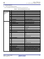
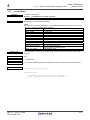
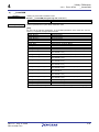
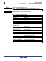
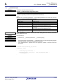
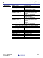
3. Standard Type
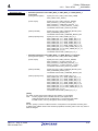
This chapter describes the standard type defined in this library. For details about the setting values, refer to the section
“4.2 Description of Each API”.
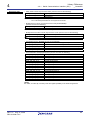
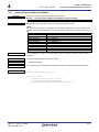
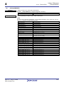
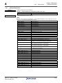
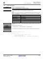
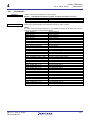
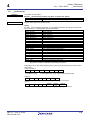
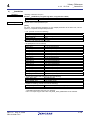
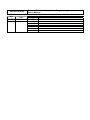
Table 3.1 Standard Type
Standard type
Description
Boolean
Boolean type represents the enum-type data that indicates whether it is true
(RAPI_TRUE (= 1)) or false (RAPI_FALSE (= 0)).
VoidFuncNotify
VoidFuncNotify type represents the type of the notification function to be registered.
Rev.1.01 Aug. 27, 2008
REJ10J1906-0101
3-1
3
Rev.1.01 Aug. 27, 2008
REJ10J1906-0101
Standard Type
3-2
Library Reference
4
4.1
API List by Peripheral Function
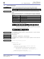
4. Library Reference
4.1.
API List by Peripheral Function
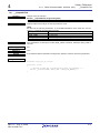
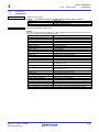
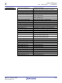
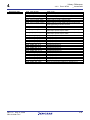
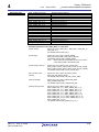
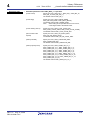
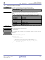
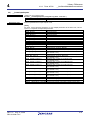
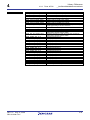
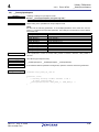
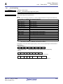
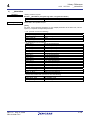
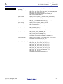
Table 4.1 and Table 4.2 list the Renesas Embedded APIs by peripheral functions.
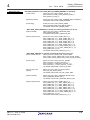
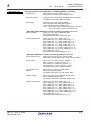
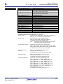
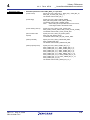
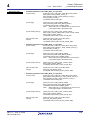
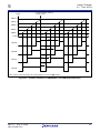
Table 4.1 Renesas Embedded API List (1/2)
Category
Serial
Communication
Interface
(SCI)
Timer
No
1
2
3
4
5
6
7
8
9
10
11
12
1
2
3
4
5
6
7
Name
__CreateSCI
__DestroySCI
__StartSCIReceiving
__StartSCISending
__StopSCIReceiving
__StopSCISending
__PollingSCIReceiving
__PollingSCISending
__GetSCIStatus
__ClearSCIStatus
__OutputSCISck
__OutputSCITxd
__CreateTimer
__EnableTimer
__DestroyTimer
__CreateEventCounter
__EnableEventCounter
__DestroyEventCounter
__GetTimerCounter
8
9
__CreatePWM
__SetPWMPin
10
11
12
13
14
__EnablePWM
__DestroyPWM
__CreatePulsePeriodMeasurementMode
__SetInputPeriodPin
__EnablePulsePeriodMeasurementMode
15
__DestroyPulsePeriodMeasurementMode
16
__GetPulsePeriodMeasurementMode
17
18
19
__CreatePulseWidthMeasurementMode
__SetInputWidthPin
__EnablePulseWidthMeasurementMode
20
__DestroyPulseWidthMeasurementMode
21
__GetPulseWidthMeasurementMode
22
23
24
25
26
27
28
29
30
31
32
__CreateInputCapture
__SetInputCapturePin
__EnableInputCapture
__DestroyInputCapture
__GetCaptureValue
__CreateOutputCompare
__SetOutputPin
__EnableOutputCompare
__DestroyOutputCompare
__GetTimerFlag
__ClearTimerFlag
Rev.1.01 Aug. 27, 2008
REJ10J1906-0101
Description
Setting of SCI
Closing of serial port
Start of SCI reception
Start of SCI transmission
Stop of SCI reception
Stop of SCI transmission
SCI reception by polling
SCI transmission by polling
Acquisition of SCI status
Clearing of SCI status
Output control for SCK pin
Output control for TXD pin
Setting for timer mode
Operation control for timer mode
Clearing of setting for timer mode
Setting for event counter mode
Operation control for event counter mode
Clearing of setting for event counter mode
Acquisition of counter value in timer mode or event
counter mode
Setting for pulse width modulation mode
Setting of timer general register for pulse width
modulation
Operation control for pulse width modulation mode
Clearing of setting for pulse width modulation mode
Setting for pulse period measurement mode
Setting of input pin for pulse period measurement
Operation control for pulse period measurement
mode
Clearing of setting for pulse period measurement
mode
Acquisition of measured value in pulse period
measurement mode
Setting for pulse width measurement mode
Setting of input pin for pulse width measurement
Operation control for pulse width measurement
mode
Clearing of setting for pulse width measurement
mode
Acquisition of measured value in pulse width
measurement mode
Setting for input capture mode
Setting of input pin for input capture
Operation control for input capture mode
Clearing of setting for input capture mode
Acquisition of counter value for input capture mode
Setting for output compare mode
Setting of timer general register for output compare
Operation control for output compare mode
Clearing of setting for output compare mode
Acquisition of timer status
Clearing of timer status
4-1
Library Reference
4
4.1
API List by Peripheral Function
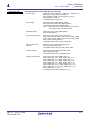
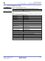
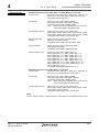
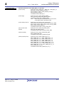
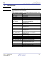
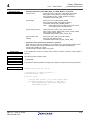
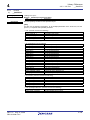
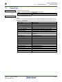
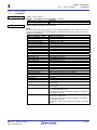
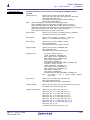
Table 4.2 Renesas Embedded API List (2/2)
Category
I/O port
External
interrupt
A/D converter
No
1
2
3
1
2
3
4
1
2
3
4
5
6
Name
__SetIOPort
__ReadIOPort
__WriteIOPort
__CreateInterrupt
__EnableInterrupt
__GetInterruptAndPinInfo
__ClearInterruptFlag
__CreateADC
__EnableADC
__DestroyADC
__GetADC
__GetADCFlag
__ClearADCFlag
Rev.1.01 Aug. 27, 2008
REJ10J1906-0101
Description
Setting of I/O port
Reading of data from I/O port
Writing of data to I/O port
Setting of external interrupt
Operation control for external interrupt
Acquisition of input-pin level for external interrupt,
and the status of interrupt request
Clearing of status of interrupt request
Setting of A/D converter
Operation control for A/D converter
Clearing of setting of A/D converter
Acquisition of A/D conversion result
Acquisition of A/D converter status
Clearing of A/D converter status
4-2
Library Reference
4
4.2.
4.2
Description of Each API
Description of Each API
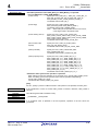
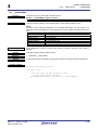
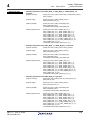
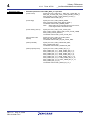
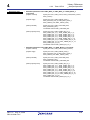
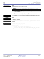
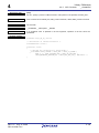
This section describes each API and explains how to use them, showing a program example for each.
of each API is divided into the following items.
Synopsis
The description
Summarizes processing by the API function, and shows its format.
Then also gives a brief explanation of arguments.
Description
Explains how to use the API function and shows assignable parameters separating
each argument with [argument].
Return value
Describes the returned value of the API function.
Category
Indicates the category of the API function.
Reference
Indicates the API functions to be referred.
Remark
Program example
Rev.1.01 Aug. 27, 2008
REJ10J1906-0101
Describes notes to use the API function.
Represents how to use the API function by a program example.
4-3
Library Reference
4
4.2.1.
1)
4.2.1
Serial Communication Interface (SCI)
__CreateSCI
Serial Communication Interface (SCI)
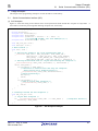
__CreateSCI
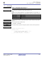
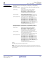
Synopsis
Description (1/2)
<Setting of SCI>
Boolean __CreateSCI( unsigned long data1, unsigned short data2 )
data1
Setup data 1
data2
Setup data 2
Sets SCI according to the specified parameters.
[data1]
For data1, set the following parameters. To set multiple parameters at the same time, use the
symbol “|” to separate each specified parameter.
• Channel: (Multiple channels can be selected)
RAPI_COM1
SCI channel 0
RAPI_COM2
SCI channel 1
RAPI_COM3
SCI channel 2
• Operation for SCI: (Choose one from the following)
Clock synchronous mode
RAPI_SM_SYNC
Clock asynchronous mode
RAPI_SM_ASYNC
• Data length format in clock asynchronous mode: (Choose one from the following)
RAPI_7_BIT_LENGTH
7-bit data length
RAPI_8_BIT_LENGTH
8-bit data length
Note: Do not set these parameters in clock synchronous mode.
• Serial/parallel conversion format: (Choose one from the following)
RAPI_LSB_SEL
LSB first
RAPI_MSB_SEL
MSB first
Note:
Do not set these parameters when 7-bit data is specified for the data length in clock
asynchronous mode.
• SCI clock source select and clock output enable/disable from SCK pin:
(Choose one from the following)
RAPI_CKDIR_INT
Internal clock, SCK pin used for input pin (CKE[1:0] = 00)
(SCK pin used for clock ouput in clock synchronous mode)
RAPI_CKDIR_EXT
External clock, SCK pin used for clock input (CKE[1:0] = 10)
(The input clock frequency is 16 times of the bit rate in clock
asynchronous mode, and synchronous clock input in clock
synchronous mode)
• Stop bit length in clock asynchronous mode:
(Choose one from the following)
RAPI_STPB_1
One stop bit
RAPI_STPB_2
Two stop bits
Note: Do not set these parameters in clock synchronous mode.
• Clock source of the on-chip baud rate generator:
(Choose one from the following)
RAPI_BCSS_P1
Pφ clock
RAPI_BCSS_P4
Pφ/4 clock
RAPI_BCSS_P16
Pφ/16 clock
RAPI_BCSS_P64
Pφ/64 clock
Rev.1.01 Aug. 27, 2008
REJ10J1906-0101
4-4
Library Reference
4
Description (2/2)
4.2.1
Serial Communication Interface (SCI)
__CreateSCI
• Parity mode in clock asynchronous mode: (Choose one from the following)
RAPI_PARITY_NON
No parity bit
RAPI_PARITY_EVEN
Even parity bit
Odd parity bit
RAPI_PARITY_ODD
Note:
• This setting is invalid in multiprocessor mode.
• Do not set these parameters in clock synchronous mode.
• Multiprocessor mode in clock asynchronous mode (enable/disable):
(Choose one from the following)
RAPI_MULTI_ENA
Enables multiprocessor mode
RAPI_MULTI_DIS
Disables multiprocessor mode
Note: Do not set these parameters in clock synchronous mode.
• Multiprocessor bit value in clock asynchronous mode: (Choose one from the following)
RAPI_MULTIPRO_BIT_H
Specifies the multiprocessor bit value to 1
RAPI_MULTIPRO_BIT_L
Specifies the multiprocessor bit value to 0
Note: Do not set these parameters in clock synchronous mode.
• SCI interrupt source: (Multiple sources can be selected)
RAPI_INT_TX_ENA
Enables the transmit-data-empty interrupt
RAPI_INT_TEND_ENA
Enables the transmit-end interrupt
RAPI_INT_RX_ERR_ENA
Enables the receive-data-full and the receive-error interrupts
RAPI_INT_ERR_ENA
Enables the receive-error interrupt
RAPI_INT_MULTI_ENA
Enables the multiprocessor interrupt
• Transmit/Receive interrupt priority level: (Choose one from the following)
RAPI_SCI_INT_LV_0
Interrupt priority level 0
RAPI_SCI_INT_LV_1
Interrupt priority level 1
Interrupt priority level 2
RAPI_SCI_INT_LV_2
RAPI_SCI_INT_LV_3
Interrupt priority level 3
RAPI_SCI_INT_LV_4
Interrupt priority level 4
RAPI_SCI_INT_LV_5
Interrupt priority level 5
RAPI_SCI_INT_LV_6
Interrupt priority level 6
RAPI_SCI_INT_LV_7
Interrupt priority level 7
RAPI_SCI_INT_LV_8
Interrupt priority level 8
Interrupt priority level 9
RAPI_SCI_INT_LV_9
RAPI_SCI_INT_LV_10
Interrupt priority level 10
RAPI_SCI_INT_LV_11
Interrupt priority level 11
RAPI_SCI_INT_LV_12
Interrupt priority level 12
RAPI_SCI_INT_LV_13
Interrupt priority level 13
RAPI_SCI_INT_LV_14
Interrupt priority level 14
RAPI_SCI_INT_LV_15
Interrupt priority level 15
[data2]
For data2, set value (N; 0≤N≤255) of bit rate register (SCBRR) in the baud rate generator.
Rev.1.01 Aug. 27, 2008
REJ10J1906-0101
4-5
Library Reference
4
4.2.1
Return value
__CreateSCI
If SCI communication is successful, RAPI_TRUE is returned; otherwise, RAPI_FALSE is
returned.
Category
SCI
Reference
none
Remark
Serial Communication Interface (SCI)
If an undefined value is specified in the first argument, operation of the API cannot be
guaranteed.
Program example
#include ”rapi_sif_sh_7125.h”
void func( void )
{
/* Setting SCI channel 0 for clock synchronous mode */
__CreateSCI( RAPI_COM1 | RAPI_SM_SYNC | RAPI_CKDIR_INT |
RAPI_BCSS_P1 | RAPI_LSB_SEL | RAPI_INT_RX_ERR_ENA |
RAPI_INT_LV_6, 20 );
}
/* Or */
void func( void )
{
/* Setting SCI channel 0 for clock asynchronous mode */
__CreateSCI( RAPI_COM1 | RAPI_SM_ASYNC | RAPI_8_BIT_LENGTH |
RAPI_LSB_SEL | RAPI_STPB_1 | RAPI_CKDIR_INT |
RAPI_BCSS_P1 | RAPI_PARITY_NON | RAPI_MULTI_DIS |
RAPI_INT_RX_ERR_ENA | RAPI_SCI_INT_LV_6, 20 );
}
Rev.1.01 Aug. 27, 2008
REJ10J1906-0101
4-6
Library Reference
4
2)
4.2.1
Serial Communication Interface (SCI)
__DestroySCI
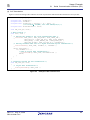
__DestroySCI
Synopsis
Description
<Closing of serial port>
Boolean __DestroySCI( unsigned long data )
data
Setup data
Stops clock supply to the specified serial port.
[data]
For data, set one of the following parameters as a channel.
RAPI_COM1
SCI channel 0
RAPI_COM2
SCI channel 1
RAPI_COM3
SCI channel 2
Return value
If the specification of serial port is invalid, RAPI_FALSE is returned; otherwise, RAPI_TRUE is
returned.
Category
SCI
Reference
__CreateSCI
Remark
If an undefined value is specified in the argument, operation of the API cannot be guaranteed.
Program example
#include ”rapi_sif_sh_7125.h”
void func( void )
{
/* Closing serial port for SCI channel 0 */
__DestroySCI( RAPI_COM1 );
}
Rev.1.01 Aug. 27, 2008
REJ10J1906-0101
4-7
Library Reference
4
3)
4.2.1
Serial Communication Interface (SCI)
__StartSCIReceiving
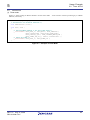
__StartSCIReceiving
Synopsis
Description
<Start of SCI reception>
Boolean __StartSCIReceiving( unsigned long data, unsigned char *RcvDtBuf,
unsigned short byteNum, unsigned short *RcvNum )
data
Setup data
RcvDtBuf
Pointer to buffer storing the received data
byteNum
Number of bytes received
RcvNum
Pointer to address storing the number of actual received data
Starts SCI reception and acquires received data with the specified number of bytes.
[data]
For data, set one of the following parameters as a channel.
RAPI_COM1
SCI channel 0
RAPI_COM2
SCI channel 1
RAPI_COM3
SCI channel 2
Return value
If start-up for SCI reception is successful, RAPI_TRUE is returned; otherwise, RAPI_FALSE is
returned.
Category
SCI
Reference
__CreateSCI, __StopSCIReceiving, __GetSCIStatus
Remark
• When executing this API function, wait for at least a 1-bit period after __CreateSCI is called.
• If an undefined value is specified in the first argument, operation of the API cannot be
guaranteed.
• The following values are stored in the reception buffer.
• High-order 8 bits: The value read from the serial status register (SCSSR).
• Low-order 8 bits: The value read from the receive data register (SCRDR).
Note: When the receive error occurs, read operation is not executed.
Program example
#include ”rapi_sif_sh_7125.h”
unsigned char ReceiveBuf[10];
unsigned short ReceiveNum;
void func( void )
{
/* Aquisition of 5-byte data by SCI reception for channel 0 */
__StartSCIReceiving( RAPI_COM1, ReceiveBuf, 5, &ReceiveNum );
}
Rev.1.01 Aug. 27, 2008
REJ10J1906-0101
4-8
Library Reference
4
4)
4.2.1
Serial Communication Interface (SCI)
__StartSCISending
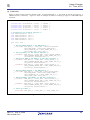
__StartSCISending
Synopsis
Description
<Start of SCI transmission>
Boolean __StartSCISending( unsigned long data, unsigned char *SndDtBuf,
unsigned short byteNum, unsigned short *SndNum )
data
Setup data
SndDtBuf
Pointer to transmit data
byteNum
Number of bytes transmitted
SndNum
Pointer to address storing the number of the actual transmitted data
Starts SCI transmission and transmits data with the specified number of bytes.
[data]
For data, set one of the following parameters as a channel.
RAPI_COM1
SCI channel 0
RAPI_COM2
SCI channel 1
RAPI_COM3
SCI channel 2
Return value
If start-up for SCI transmission is successful, RAPI_TRUE is returned; otherwise, RAPI_FALSE
is returned.
Category
SCI
Reference
__CreateSCI, __StopSCISending, __GetSCIStatus
Remark
• When executing this API function, wait for at least a 1-bit period after __CreateSCI is called.
• If an undefined value is specified in the first argument, operation of the API cannot be
guaranteed.
Program example
#include ”rapi_sif_sh_7125.h”
unsigned char SendBuf[10];
unsigned short SendNum;
void func( void )
{
/* Start-up SCI transmission for 5-byte data */
__StartSCISending( RAPI_COM1, SendBuf, 5, &SendNum );
}
Rev.1.01 Aug. 27, 2008
REJ10J1906-0101
4-9
Library Reference
4
5)
4.2.1
Serial Communication Interface (SCI)
__StopSCIReceiving
__StopSCIReceiving
Synopsis
Description
<Stop of SCI reception>
Boolean __StopSCIReceiving( unsigned long data1, unsigned short data2 )
data1
Setup data 1
data2
Setup data 2
Stops SCI reception.
[data1]
For data1, set one of the following parameters as a channel.
RAPI_COM1
SCI channel 0
RAPI_COM2
SCI channel 1
RAPI_COM3
SCI channel 2
[data2]
For data2, specify the wait time until stopping SCI reception.
Return value
If stop of SCI reception is successful and there are no receive errors, RAPI_TRUE is returned;
otherwise, RAPI_FALSE is returned.
Category
SCI
Reference
__StartSCIReceiving
Remark
If an undefined value is specified in the argument, operation of the API cannot be guaranteed.
Program example
#include ”rapi_sif_sh_7125.h”
void func( void )
{
/* Stopping SCI reception for channel 0 */
__StopSCIReceiving( RAPI_COM1, 50000 );
}
Rev.1.01 Aug. 27, 2008
REJ10J1906-0101
4-10
Library Reference
4
6)
4.2.1
Serial Communication Interface (SCI)
__StopSCISending
__StopSCISending
Synopsis
Description
<Stop of SCI transmission>
Boolean __StopSCISending( unsigned long data1, unsigned short data2 )
data1
Setup data 1
data2
Setup data 2
Stops SCI transmission.
[data1]
For data1, set one of the following parameters as a channel.
RAPI_COM1
SCI channel 0
RAPI_COM2
SCI channel 1
RAPI_COM3
SCI channel 2
[data2]
For data2, specify the wait time until SCI transmission is stopped.
Return value
If stop of SCI transmission is successful, RAPI_TRUE is returned; otherwise, RAPI_FALSE is
returned.
Category
SCI
Reference
__StartSCISending
Remark
• When executing in clock synchronous mode, SCI reception of data also stops.
• If an undefined value is specified in the first argument, operation of the API cannot be
guaranteed.
Program example
#include ”rapi_sif_sh_7125.h”
void func( void )
{
/* Stopping SCI transmission for channel 0 */
__StopSCISending( RAPI_COM1, 50000 );
}
Rev.1.01 Aug. 27, 2008
REJ10J1906-0101
4-11
Library Reference
4
7)
4.2.1
Serial Communication Interface (SCI)
__PollingSCIReceiving
__PollingSCIReceiving
Synopsis
Description
<SCI reception by polling>
Boolean __PollingSCIReceiving( unsigned long data )
data
Setup data
Receives data in serial communication by polling.
Acquires data with the size specified by __StartSCIReceiving.
[data]
For data, set one of the following parameters as a channel.
RAPI_COM1
SCI channel 0
RAPI_COM2
SCI channel 1
RAPI_COM3
SCI channel 2
Return value
If the specification of serial port or the received data is invalid, RAPI_FALSE is returned;
otherwise, RAPI_TRUE is returned.
Category
SCI
Reference
__GetSCIStatus, __StartSCIReceiving
Remark
If an undefined value is specified in the argument, operation of the API cannot be guaranteed.
Program example
#include ”rapi_sif_sh_7125.h”
unsigned char ReceiveBuf[10];
unsigned short ReceiveNum;
void INT_SCI0_RX( void );
void ErrorOpe( void );
/* Main routine */
void func( void )
{
/* Setting SCI channel 0 to clock synchronous mode
(Receive-data-full and receive-error interrupts enabled) */
__CreateSCI( RAPI_COM1 | RAPI_SM_SYNC | RAPI_CKDIR_INT |
RAPI_BCSS_P1 | RAPI_LSB_SEL | RAPI_INT_RX_ERR_ENA |
RAPI_SCI_INT_LV_6, 20 );
/* Setting receive-data size to 5 bytes and
Start-up SCI reception */
__StartSCIReceiving( RAPI_COM1, ReceiveBuf, 5, &ReceiveNum );
}
/* Interrupt routine for SCI reception */
void INT_SCI0_RX( void )
{
/* Reception of 5-byte data */
if( __PollingSCIReceiving( RAPI_COM1 ) == RAPI_TRUE ){
/* Reception success */
if( ReceiveNum == 5 ){
/* End of 5-byte data reception*/
__StopSCIReceiving( RAPI_COM1, 5000 );
}
}
else{
/* Reception failure */
ErrorOpe();
/* Error processing */
}
}
Rev.1.01 Aug. 27, 2008
REJ10J1906-0101
4-12
Library Reference
4
8)
4.2.1
Serial Communication Interface (SCI)
__PollingSCISending
__PollingSCISending
Synopsis
Description
<SCI transmission by polling>
Boolean __PollingSCISending( unsigned long data )
data
Setup data
Transmits data in the serial communication by polling. Transmits data in transmission buffer with
the size specified by __StartSCISending.
[data]
For data, set one of the following parameters as a channel.
RAPI_COM1
SCI channel 0
RAPI_COM2
SCI channel 1
RAPI_COM3
SCI channel 2
Return value
If the specification of serial port is invalid, RAPI_FALSE is returned; otherwise, RAPI_TRUE is
returned.
Category
SCI
Reference
__StartSCISending
Remark
If an undefined value is specified in the argument, operation of the API cannot be guaranteed.
Program example
#include ”rapi_sif_sh_7125.h”
unsigned char SendBuf[10];
unsigned short SendNum;
void INT_SCI0_TX( void );
/* Main routine */
void func( void )
{
/* Setting up SCI channel 0 to clock synchronous mode
(Transmit-data-empty interrupt enabled) */
__CreateSCI( RAPI_COM1 | RAPI_SM_SYNC | RAPI_CKDIR_INT |
RAPI_BCSS_P1 | RAPI_LSB_SEL | RAPI_INT_TX_ENA |
RAPI_SCI_INT_LV_6, 20 );
/* Setting transmit-data size to 5 bytes and
start-up SCI transmission */
__StartSerialSending( RAPI_COM1, SendBuf, 5, &SendNum );
}
/* Interrupt routine for SCI transmission */
void INT_SCI0_TX( void )
{
if( SendNum == 5 ){
/* End of 5-byte data transmission*/
__StopSCIsending( RAPI_COM1, 5000 );
}
else{
/* Transmission of 5-byte data */
__PollingSCISending( RAPI_COM1 );
}
}
Rev.1.01 Aug. 27, 2008
REJ10J1906-0101
4-13
Library Reference
4
9)
4.2.1
Serial Communication Interface (SCI)
__GetSCIStatus
__GetSCIStatus
Synopsis
Description
<Acquisition of SCI status>
Boolean __GetSCIStatus( unsigned long data, unsigned char *status )
data
Setup data
status
Byte address to store the receive error flag
Acquires status of SCI transmission/reception.
[data]
For data, set the following parameters. To set multiple parameters at the same time, use the
symbol “|” to separate each specified parameter.
RAPI_COM1
SCI channel 0
RAPI_COM2
SCI channel 1
RAPI_COM3
SCI channel 2
RAPI_TDRE
Transmit-data-register empty flag
RAPI_RDRF
Receive-data-register full flag
RAPI_ORER
Overrun error flag
RAPI_FER
Framing error flag
RAPI_PER
Parity error flag
RAPI_TEND
Transmit end flag
RAPI_MPB
Multiprocessor bit flag for reception
RAPI_MPBT
Multiprocessor bit flag for transmission
RAPI_RECV_ERROR
All receive error flags
(Overrun, framing, and parity errors)
RAPI_ALL_FLAG
All status flags of SCI
Return value
If the specification of serial port is invalid, RAPI_FALSE is returned; otherwise, RAPI_TRUE is
returned.
Category
SCI
Reference
__ClearSCIStatus
Remark
If an undefined value is specified in the first argument, operation of the API cannot be
guaranteed.
Program example
#include ”rapi_sif_sh_7125.h”
unsigned char statusvalue;
void func( void )
{
/* Acquisition of parity error flag for SCI channel 0 */
return __GetSCIStatus( RAPI_COM1 | RAPI_PER, &statusvalue );
}
Rev.1.01 Aug. 27, 2008
REJ10J1906-0101
4-14
Library Reference
4
4.2.1
10)
Serial Communication Interface (SCI)
__ClearSCIStatus
__ClearSCIStatus
Synopsis
Description
<Clearing of SCI status>
Boolean __ClearSCIStatus( unsigned long data )
data
Setup data
Clears status of SCI transmission/reception.
[data]
For data, set the following parameters. To set multiple parameters at the same time, use the
symbol “|” to separate each specified parameter.
RAPI_COM1
SCI channel 0
RAPI_COM2
SCI channel 1
RAPI_COM3
SCI channel 2
RAPI_TDRE
Transmit-data-register empty flag
RAPI_RDRF
Receive-data-register full flag
RAPI_ORER
Overrun error flag
RAPI_FER
Framing error flag
RAPI_PER
Parity error flag
RAPI_TEND
Transmit end flag
RAPI_MPB
Multiprocessor bit flag for reception
RAPI_MPBT
Multiprocessor bit flag for transmission
RAPI_RECV_ERROR
All receive error flags of SCI
(Overrun, framing, and parity errors)
RAPI_ALL_FLAG
All status flags of SCI
Return value
If the specification of serial port is invalid, RAPI_FALSE is returned; otherwise, RAPI_TRUE is
returned.
Category
SCI
Reference
__GetSCIStatus
Remark
If an undefined value is specified in the argument, operation of the API cannot be guaranteed.
Program example
#include ”rapi_sif_sh_7125.h”
void func( void )
{
/* Clearing parity error flag for SCI channel 0 */
return __ClearSCIStatus( RAPI_COM1 | RAPI_PER );
}
Rev.1.01 Aug. 27, 2008
REJ10J1906-0101
4-15
Library Reference
4
4.2.1
11)
Serial Communication Interface (SCI)
__OutputSCISck
__OutputSCISck
Synopsis
Description
<Output control for SCK pin>
Boolean __OutputSCISck( unsigned long data )
data
Setup data
Controls output of the SCK pin in clock asynchronous mode.
[data]
For data, set the following parameters. To set multiple parameters at the same time, use the
symbol “|” to separate each specified parameter.
RAPI_COM1
SCI channel 0
RAPI_COM2
SCI channel 1
RAPI_COM3
SCI channel 2
RAPI_SCK_OUTPUT
Outputs clock with a frequency of 16 times of the bit rate
RAPI_SCK_NO_OUTPUT
Does not output the SPB1DT bit value in serial port register
(SCSPTR) through the SCK pin
RAPI_SCK_OUTPUT_L
Outputs the SPB1DT bit value in serial port register
(SCSPTR) at low level through the SCK pin
RAPI_SCK_OUTPUT_H
Outputs the SPB1DT bit value in serial port register
(SCSPTR) at high level through the SCK pin
Return value
If the specification of serial port is invalid, RAPI_FALSE is returned; otherwise, RAPI_TRUE is
returned.
Category
SCI
Reference
__CreateSCI
Remark
• When using the SCK pin as a port output pin, set the internal clock (RAPI_CKDIR_INT) as
the clock source in __CreateSCI beforehand.
• If an undefined value is specified in the argument, operation of the API cannot be
guaranteed.
Program example
#include ”rapi_sif_sh_7125.h”
void func( void )
{
/* Setting up SCK pin as high-level output for channel 0 */
return __OutputSCISck( RAPI_COM1 | RAPI_SCK_OUTPUT_H );
}
Rev.1.01 Aug. 27, 2008
REJ10J1906-0101
4-16
Library Reference
4
4.2.1
12)
Serial Communication Interface (SCI)
__OutputSCITxd
__OutputSCITxd
Synopsis
Description
<Output control for TXD pin>
Boolean __OutputSCITxd( unsigned long data )
data
Setup data
Controls output of the TXD pin in clock asynchronous mode.
[data]
For data, set the following parameters. To set multiple parameters at the same time, use the
symbol “|” to separate each specified parameter.
RAPI_COM1
SCI channel 0
RAPI_COM2
SCI channel 1
RAPI_COM3
SCI channel 2
RAPI_TXD_BREAK_L
Sets the TXD pin as low-level output
RAPI_TXD_BREAK_H
Sets the TXD pin as high-level output
Return value
If the specification of serial port is invalid, RAPI_FALSE is returned; otherwise, RAPI_TRUE is
returned.
Category
SCI
Reference
none
Remark
If an undefined value is specified in the argument, operation of the API cannot be guaranteed.
Program example
#include ”rapi_sif_sh_7125.h”
void func( void )
{
/* Setting up TXD pin as high-level output for channel 0 */
return __OutputSCITxd( RAPI_COM1 | RAPI_TXD_BREAK_H );
}
Rev.1.01 Aug. 27, 2008
REJ10J1906-0101
4-17
Library Reference
4
4.2.2
4.2.2.
Timer MTU2
1)
__CreateTimer
Synopsis
Description (1/7)
Timer MTU2
__CreateTimer
<Setting for timer mode>
Boolean __CreateTimer( unsigned long data1, unsigned short data2, void *func )
data1
Setup data 1
data2
Setup data 2
func
Pointer to callback function
Sets the specified timer to timer mode.
[data1]
For data1, set the following parameters. To set multiple parameters at the same time, use the
symbol “|” to separate each specified parameter.
RAPI_MTU2_0
MTU2 channel 0
RAPI_MTU2_1
MTU2 channel 1
RAPI_MTU2_2
MTU2 channel 2
RAPI_MTU2_3
MTU2 channel 3
RAPI_MTU2_4
MTU2 channel 4
RAPI_MTU2_5U
MTU2 channel 5U
RAPI_MTU2_5V
MTU2 channel 5V
RAPI_MTU2_5W
MTU2 channel 5W
RAPI_CMT_0
CMT channel 0
RAPI_CMT_1
CMT channel 1
RAPI_MP1
Internal clock: counts on MPφ/1
RAPI_MP4
Internal clock: counts on MPφ/4
RAPI_MP16
Internal clock: counts on MPφ/16
RAPI_MP64
Internal clock: counts on MPφ/64
RAPI_MP256_1
Internal clock: counts on MPφ/256 (for channel 1)
RAPI_MP256_34
Internal clock: counts on MPφ/256
(for channel 3 or 4)
RAPI_MP1024_2
Internal clock: counts on MPφ/1024 (for channel 2)
RAPI_MP1024_34
Internal clock: counts on MPφ/1024
(for channel 3 or 4)
RAPI_P8
Internal clock: counts on Pφ/8
RAPI_P32
Internal clock: counts on Pφ/32
RAPI_P128
Internal clock: counts on Pφ/128
RAPI_P512
Internal clock: counts on Pφ/512
RAPI_FREE_RUNNING
Free-running count operation
RAPI_PERIODIC
Periodic count operation
RAPI_RISING_EDGE
Counts at rising edge
RAPI_FALLING_EDGE
Counts at falling edge
RAPI_BOTH_EDGE
Counts at both edges
Note: When MPφ/1 is specified for the count source, count edge is fixed to rising edge.
Rev.1.01 Aug. 27, 2008
REJ10J1906-0101
4-18
Library Reference
4
Description (2/7)
4.2.2
RAPI_TCNT_CLEAR_DIS
RAPI_TCNT_CLEAR_TGRA
RAPI_TCNT_CLEAR_TGRB
RAPI_TCNT_CLEAR_TGRC
RAPI_TCNT_CLEAR_TGRD
RAPI_TCNT_CLEAR_DIS_TGRE
RAPI_TCNT_CLEAR_DIS_TGRF
RAPI_TCNT_CLEAR_TGRU
RAPI_TCNT_CLEAR_TGRV
RAPI_TCNT_CLEAR_TGRW
RAPI_OUTPUT_RETAIN
RAPI_OUTPUT_0_0
RAPI_OUTPUT_0_1
RAPI_OUTPUT_0_TOG
RAPI_OUTPUT_1_0
RAPI_OUTPUT_1_1
RAPI_OUTPUT_1_TOG
RAPI_OVERFLOW_ENA
RAPI_OVERFLOW_DIS
RAPI_COMPARE_MATCH_ENA
RAPI_COMPARE_MATCH_DIS
RAPI_AD_START_REQ
RAPI_NO_AD_START_REQ
RAPI_TIMER_INT_LV_0
RAPI_TIMER_INT_LV_1
RAPI_TIMER_INT_LV_2
RAPI_TIMER_INT_LV_3
RAPI_TIMER_INT_LV_4
RAPI_TIMER_INT_LV_5
RAPI_TIMER_INT_LV_6
RAPI_TIMER_INT_LV_7
RAPI_TIMER_INT_LV_8
RAPI_TIMER_INT_LV_9
RAPI_TIMER_INT_LV_10
RAPI_TIMER_INT_LV_11
RAPI_TIMER_INT_LV_12
RAPI_TIMER_INT_LV_13
RAPI_TIMER_INT_LV_14
RAPI_TIMER_INT_LV_15
Rev.1.01 Aug. 27, 2008
REJ10J1906-0101
Timer MTU2
__CreateTimer
Disables TCNT clearing
(selectable only in TGRE and TGRF of channel 0)
Clears TCNT by TGRA compare match
Clears TCNT by TGRB compare match
Clears TCNT by TGRC compare match
Clears TCNT by TGRD compare match
Uses TGRE register, but disables TCNT clearing by
TGRE compare match
Uses TGRF register, but disables TCNT clearing by
TGRF compare match
Clears TCNT by TGRU_5 compare match
Clears TCNT by TGRV_5 compare match
Clears TCNT by TGRW_5 compare match
Output retained
Initial output is 0, and outputs 0at compare match
Initial output is 0, and outputs 1 at compare match
Initial output is 0, and outputs toggle at compare match
Initial output is 1, and outputs 0 at compare match
Initial output is 1, and outputs 1 at compare match
Initial output is 1, and outputs toggle at compare match
Enables overflow interrupt
Disables overflow interrupt
Enables compare match interrupt
Disables compare match interrupt
Enables generation of A/D converter start requests by
TGRA input capture/compare match
Disables generation of A/D converter start requests by
TGRA input capture/compare match
Interrupt priority level 0
Interrupt priority level 1
Interrupt priority level 2
Interrupt priority level 3
Interrupt priority level 4
Interrupt priority level 5
Interrupt priority level 6
Interrupt priority level 7
Interrupt priority level 8
Interrupt priority level 9
Interrupt priority level 10
Interrupt priority level 11
Interrupt priority level 12
Interrupt priority level 13
Interrupt priority level 14
Interrupt priority level 15
4-19
Library Reference
4
Description (3/7)
4.2.2
Timer MTU2
__CreateTimer
• Selectable parameters when RAPI_MTU2_0 is specified:
(Count source)
Specify one from { RAPI_MP1, RAPI_MP4, RAPI_MP16,
RAPI_MP64 }. The default value is RAPI_MP1.
(Operation method)
Specify one from { RAPI_FREE_RUNNING, RAPI_PERIODIC }.
The default value is RAPI_FREE_RUNNING.
(Count edge)
Specify one from { RAPI_FALLING_EDGE,
RAPI_RISING_EDGE, RAPI_BOTH_EDGE }.
The default value is RAPI_RISING_EDGE.
Note:
When RAPI_MP1 is specified for the count source,
count edge is fixed to the default value.
• When RAPI_FREE_RUNNING is selected, the following parameters can be set:
(Interrupt enable)
Specify one from { RAPI_OVERFLOW_ENA,
RAPI_OVERFLOW_DIS }.
The default value is RAPI_OVERFLOW_DIS.
(Interrupt priority level)
Specify one from { RAPI_TIMER_INT_LV_0,
RAPI_TIMER_INT_LV_1, RAPI_TIMER_INT_LV_2,
RAPI_TIMER_INT_LV_3, RAPI_TIMER_INT_LV_4,
RAPI_TIMER_INT_LV_5, RAPI_TIMER_INT_LV_6,
RAPI_TIMER_INT_LV_7, RAPI_TIMER_INT_LV_8,
RAPI_TIMER_INT_LV_9, RAPI_TIMER_INT_LV_10,
RAPI_TIMER_INT_LV_11, RAPI_TIMER_INT_LV_12,
RAPI_TIMER_INT_LV_13, RAPI_TIMER_INT_LV_14,
RAPI_TIMER_INT_LV_15 }.
The default value is RAPI_TIMER_INT_LV_0.
• When RAPI_PERIODIC is selected, the following parameters can be set:
(Count clearing source)
Specify one from { RAPI_TCNT_CLEAR_DIS,
RAPI_TCNT_CLEAR_TGRA, RAPI_TCNT_CLEAR_TGRB,
RAPI_TCNT_CLEAR_TGRC, RAPI_TCNT_CLEAR_TGRD,
RAPI_TCNT_CLEAR_DIS_TGRE,
RAPI_TCNT_CLEAR_DIS_TGRF }.
The default value is RAPI_TCNT_CLEAR_DIS.
Rev.1.01 Aug. 27, 2008
REJ10J1906-0101
(Count output)
Specify one from { RAPI_OUTPUT_RETAIN,
RAPI_OUTPUT_0_0, RAPI_OUTPUT_0_1,
RAPI_OUTPUT_0_TOG, RAPI_OUTPUT_1_0,
RAPI_OUTPUT_1_1, RAPI_OUTPUT_1_TOG }.
The default value is RAPI_OUTPUT_RETAIN.
(A/D converter start
request)
Specify one from { RAPI_AD_START_REQ,
RAPI_NO_AD_START_REQ }.
The default value is RAPI_NO_AD_START_REQ.
(Interrupt enable)
Specify one from { RAPI_COMPARE_MATCH_ENA,
RAPI_COMPARE_MATCH_DIS }.
The default value is RAPI_COMPARE_MATCH_DIS.
(Interrupt priority level)
Specify one from { RAPI_TIMER_INT_LV_0,
RAPI_TIMER_INT_LV_1, RAPI_TIMER_INT_LV_2,
RAPI_TIMER_INT_LV_3, RAPI_TIMER_INT_LV_4,
RAPI_TIMER_INT_LV_5, RAPI_TIMER_INT_LV_6,
RAPI_TIMER_INT_LV_7, RAPI_TIMER_INT_LV_8,
RAPI_TIMER_INT_LV_9, RAPI_TIMER_INT_LV_10,
RAPI_TIMER_INT_LV_11, RAPI_TIMER_INT_LV_12,
RAPI_TIMER_INT_LV_13, RAPI_TIMER_INT_LV_14,
RAPI_TIMER_INT_LV_15 }.
The default value is RAPI_TIMER_INT_LV_0.
4-20
Library Reference
4
Description (4/7)
4.2.2
Timer MTU2
__CreateTimer
• Selectable parameters when RAPI_MTU2_1 is specified:
(Count source)
Specify one from { RAPI_MP1, RAPI_MP4, RAPI_MP16,
RAPI_MP64, RAPI_MP256_1 }.
The default value is RAPI_MP1.
(Operation method)
Specify one from { RAPI_FREE_RUNNING, RAPI_PERIODIC }.
The default value is RAPI_FREE_RUNNING.
(Count edge)
Specify one from { RAPI_RISING_EDGE,
RAPI_FALLING_EDGE, RAPI_BOTH_EDGE }.
The default value is RAPI_RISING_EDGE.
Note:
When RAPI_MP1 is specified for the count source,
count edge is fixed to the default value.
• When RAPI_FREE_RUNNING is selected, the following parameters can be set:
(Interrupt enable)
Specify one from { RAPI_OVERFLOW_ENA,
RAPI_OVERFLOW_DIS }.
The default value is RAPI_OVERFLOW_DIS.
(Interrupt priority level)
Specify one from { RAPI_TIMER_INT_LV_0,
RAPI_TIMER_INT_LV_1, RAPI_TIMER_INT_LV_2,
RAPI_TIMER_INT_LV_3, RAPI_TIMER_INT_LV_4,
RAPI_TIMER_INT_LV_5, RAPI_TIMER_INT_LV_6,
RAPI_TIMER_INT_LV_7, RAPI_TIMER_INT_LV_8,
RAPI_TIMER_INT_LV_9, RAPI_TIMER_INT_LV_10,
RAPI_TIMER_INT_LV_11, RAPI_TIMER_INT_LV_12,
RAPI_TIMER_INT_LV_13, RAPI_TIMER_INT_LV_14,
RAPI_TIMER_INT_LV_15 }.
The default value is RAPI_TIMER_INT_LV_0.
• When RAPI_PERIODIC is selected, the following parameters can be set:
(Count clearing source)
Specify one from { RAPI_ TCNT_CLEAR_TGRA,
RAPI_ TCNT_CLEAR_TGRB }.
The default value is RAPI_TCNT_CLEAR_DIS.
Rev.1.01 Aug. 27, 2008
REJ10J1906-0101
(Count output)
Specify one from { RAPI_OUTPUT_RETAIN,
RAPI_OUTPUT_0_0, RAPI_OUTPUT_0_1,
RAPI_OUTPUT_0_TOG, RAPI_OUTPUT_1_0,
RAPI_OUTPUT_1_1, RAPI_OUTPUT_1_TOG }.
The default value is RAPI_OUTPUT_RETAIN.
(A/D converter start
request)
Specify one from { RAPI_AD_START_REQ,
RAPI_NO_AD_START_REQ }.
The default value is RAPI_NO_AD_START_REQ.
(Interrupt enable)
Specify one from { RAPI_COMPARE_MATCH_ENA,
RAPI_COMPARE_MATCH_DIS }.
The default value is RAPI_COMPARE_MATCH_DIS.
(Interrupt priority level)
Specify one from { RAPI_TIMER_INT_LV_0,
RAPI_TIMER_INT_LV_1, RAPI_TIMER_INT_LV_2,
RAPI_TIMER_INT_LV_3, RAPI_TIMER_INT_LV_4,
RAPI_TIMER_INT_LV_5, RAPI_TIMER_INT_LV_6,
RAPI_TIMER_INT_LV_7, RAPI_TIMER_INT_LV_8,
RAPI_TIMER_INT_LV_9, RAPI_TIMER_INT_LV_10,
RAPI_TIMER_INT_LV_11, RAPI_TIMER_INT_LV_12,
RAPI_TIMER_INT_LV_13, RAPI_TIMER_INT_LV_14,
RAPI_TIMER_INT_LV_15 }.
The default value is RAPI_TIMER_INT_LV_0.
4-21
Library Reference
4
Description (5/7)
4.2.2
Timer MTU2
__CreateTimer
• Selectable parameters when RAPI_MTU2_2 is specified:
(Count source)
Specify one from { RAPI_MP1, RAPI_MP4, RAPI_MP16,
RAPI_MP64, RAPI_MP1024_2 }.
The default value is RAPI_MP1.
(Operation method)
Specify one from { RAPI_FREE_RUNNING, RAPI_PERIODIC }.
The default value is RAPI_FREE_RUNNING.
(Count edge)
Specify one from { RAPI_RISING_EDGE,
RAPI_FALLING_EDGE, RAPI_BOTH_EDGE }.
The default value is RAPI_RISING_EDGE.
Note:
When RAPI_MP1 is specified for the count source,
count edge is fixed to the default value.
• When RAPI_FREE_RUNNING is selected, the following parameters can be set:
(Interrupt enable)
Specify one from { RAPI_OVERFLOW_ENA,
RAPI_OVERFLOW_DIS }.
The default value is RAPI_OVERFLOW_DIS.
(Interrupt priority level)
Specify one from { RAPI_TIMER_INT_LV_0,
RAPI_TIMER_INT_LV_1, RAPI_TIMER_INT_LV_2,
RAPI_TIMER_INT_LV_3, RAPI_TIMER_INT_LV_4,
RAPI_TIMER_INT_LV_5, RAPI_TIMER_INT_LV_6,
RAPI_TIMER_INT_LV_7, RAPI_TIMER_INT_LV_8,
RAPI_TIMER_INT_LV_9, RAPI_TIMER_INT_LV_10,
RAPI_TIMER_INT_LV_11, RAPI_TIMER_INT_LV_12,
RAPI_TIMER_INT_LV_13, RAPI_TIMER_INT_LV_14,
RAPI_TIMER_INT_LV_15 }.
The default value is RAPI_TIMER_INT_LV_0.
• When RAPI_PERIODIC is selected, the following parameters can be set:
(Count clearing source)
Specify one from { RAPI_ TCNT_CLEAR_TGRA,
RAPI_ TCNT_CLEAR_TGRB }.
The default value is RAPI_TCNT_CLEAR_DIS.
Rev.1.01 Aug. 27, 2008
REJ10J1906-0101
(Count output)
Specify one from { RAPI_OUTPUT_RETAIN,
RAPI_OUTPUT_0_0, RAPI_OUTPUT_0_1,
RAPI_OUTPUT_0_TOG, RAPI_OUTPUT_1_0,
RAPI_OUTPUT_1_1, RAPI_OUTPUT_1_TOG }.
The default value is RAPI_OUTPUT_RETAIN.
(A/D converter start
request)
Specify one from { RAPI_AD_START_REQ,
RAPI_NO_AD_START_REQ }.
The default value is RAPI_NO_AD_START_REQ.
(Interrupt enable)
Specify one from { RAPI_COMPARE_MATCH_ENA,
RAPI_COMPARE_MATCH_DIS }.
The default value is RAPI_COMPARE_MATCH_DIS.
(Interrupt priority level)
Specify one from { RAPI_TIMER_INT_LV_0,
RAPI_TIMER_INT_LV_1, RAPI_TIMER_INT_LV_2,
RAPI_TIMER_INT_LV_3, RAPI_TIMER_INT_LV_4,
RAPI_TIMER_INT_LV_5, RAPI_TIMER_INT_LV_6,
RAPI_TIMER_INT_LV_7, RAPI_TIMER_INT_LV_8,
RAPI_TIMER_INT_LV_9, RAPI_TIMER_INT_LV_10,
RAPI_TIMER_INT_LV_11, RAPI_TIMER_INT_LV_12,
RAPI_TIMER_INT_LV_13, RAPI_TIMER_INT_LV_14,
RAPI_TIMER_INT_LV_15 }.
The default value is RAPI_TIMER_INT_LV_0.
4-22
Library Reference
4
Description (6/7)
4.2.2
Timer MTU2
__CreateTimer
• Selectable parameters when RAPI_MTU2_3 or RAPI_MTU2_4 is specified:
(Count source)
Specify one from { RAPI_MP1, RAPI_MP4, RAPI_MP16,
RAPI_MP64, RAPI_MP256_34, RAPI_MP1024_34 }.
The default value is RAPI_MP1.
(Operation method)
Specify one from { RAPI_FREE_RUNNING, RAPI_PERIODIC }.
The default value is RAPI_FREE_RUNNING.
(Count edge)
Specify one from { RAPI_RISING_EDGE,
RAPI_FALLING_EDGE, RAPI_BOTH_EDGE }.
The default value is RAPI_RISING_EDGE.
Note:
When RAPI_MP1 is specified for the count source,
count edge is fixed to the default value.
• When RAPI_FREE_RUNNING is selected, the following parameters can be set:
(Interrupt enable)
Specify one from { RAPI_OVERFLOW_ENA,
RAPI_OVERFLOW_DIS }.
The default value is RAPI_OVERFLOW_DIS.
(Interrupt priority level)
Specify one from { RAPI_TIMER_INT_LV_0,
RAPI_TIMER_INT_LV_1, RAPI_TIMER_INT_LV_2,
RAPI_TIMER_INT_LV_3, RAPI_TIMER_INT_LV_4,
RAPI_TIMER_INT_LV_5, RAPI_TIMER_INT_LV_6,
RAPI_TIMER_INT_LV_7, RAPI_TIMER_INT_LV_8,
RAPI_TIMER_INT_LV_9, RAPI_TIMER_INT_LV_10,
RAPI_TIMER_INT_LV_11, RAPI_TIMER_INT_LV_12,
RAPI_TIMER_INT_LV_13, RAPI_TIMER_INT_LV_14,
RAPI_TIMER_INT_LV_15 }.
The default value is RAPI_TIMER_INT_LV_0.
• When RAPI_PERIODIC is selected, the following parameters can be set:
(Count clearing source)
Specify one from { RAPI_ TCNT_CLEAR_TGRA,
RAPI_TCNT_CLEAR_TGRB, RAPI_TCNT_CLEAR_TGRC,
RAPI_TCNT_CLEAR_TGRD }.
The default value is RAPI_ TCNT_CLEAR_DIS.
Rev.1.01 Aug. 27, 2008
REJ10J1906-0101
(Count output)
Specify one from { RAPI_OUTPUT_RETAIN,
RAPI_OUTPUT_0_0, RAPI_OUTPUT_0_1,
RAPI_OUTPUT_0_TOG, RAPI_OUTPUT_1_0,
RAPI_OUTPUT_1_1, RAPI_OUTPUT_1_TOG }.
The default value is RAPI_OUTPUT_RETAIN.
(A/D converter start
request)
Specify one from { RAPI_AD_START_REQ,
RAPI_NO_AD_START_REQ }.
The default value is RAPI_NO_AD_START_REQ.
(Interrupt enable)
Specify one from { RAPI_COMPARE_MATCH_ENA,
RAPI_COMPARE_MATCH_DIS }.
The default value is RAPI_COMPARE_MATCH_DIS.
(Interrupt priority level)
Specify one from { RAPI_TIMER_INT_LV_0,
RAPI_TIMER_INT_LV_1, RAPI_TIMER_INT_LV_2,
RAPI_TIMER_INT_LV_3, RAPI_TIMER_INT_LV_4,
RAPI_TIMER_INT_LV_5, RAPI_TIMER_INT_LV_6,
RAPI_TIMER_INT_LV_7, RAPI_TIMER_INT_LV_8,
RAPI_TIMER_INT_LV_9, RAPI_TIMER_INT_LV_10,
RAPI_TIMER_INT_LV_11, RAPI_TIMER_INT_LV_12,
RAPI_TIMER_INT_LV_13, RAPI_TIMER_INT_LV_14,
RAPI_TIMER_INT_LV_15 }.
The default value is RAPI_TIMER_INT_LV_0.
4-23
Library Reference
4
Description (7/7)
4.2.2
Timer MTU2
__CreateTimer
• Selectable parameters when RAPI_MTU2_5 is specified:
(Count source)
Specify one from { RAPI_MP1, RAPI_MP4, RAPI_MP16,
RAPI_MP64 }. The default value is RAPI_MP1.
(Operation method)
Only RAPI_PERIODIC can be selected.
(Count clearing source)
Specify one from { RAPI_TCNT_CLEAR_DIS,
RAPI_TCNT_CLEAR_TGRU, RAPI_TCNT_CLEAR_TGRV,
RAPI_TCNT_CLEAR_TGRW }.
The default value is RAPI_TCNT_CLEAR_DIS.
(Interrupt enable)
Specify one from { RAPI_COMPARE_MATCH_ENA,
RAPI_COMPARE_MATCH_DIS }.
The default value is RAPI_COMPARE_MATCH_DIS.
(Interrupt priority level)
Specify one from { RAPI_TIMER_INT_LV_0,
RAPI_TIMER_INT_LV_1, RAPI_TIMER_INT_LV_2,
RAPI_TIMER_INT_LV_3, RAPI_TIMER_INT_LV_4,
RAPI_TIMER_INT_LV_5, RAPI_TIMER_INT_LV_6,
RAPI_TIMER_INT_LV_7, RAPI_TIMER_INT_LV_8,
RAPI_TIMER_INT_LV_9, RAPI_TIMER_INT_LV_10,
RAPI_TIMER_INT_LV_11, RAPI_TIMER_INT_LV_12,
RAPI_TIMER_INT_LV_13, RAPI_TIMER_INT_LV_14,
RAPI_TIMER_INT_LV_15 }.
The default value is RAPI_TIMER_INT_LV_0.
• Selectable parameters when RAPI_CMT_0 or RAPI_CMT_1 is specified:
(Channel)
Specify one from { RAPI_CMT_0, RAPI_CMT_1 }.
(Count source)
Specify one from { RAPI_P8, RAPI_P32, RAPI_P128,
RAPI_P512 }.
The default value is RAPI_MP8.
(Interrupt enable)
Specify one from { RAPI_COMPARE_MATCH_ENA,
RAPI_COMPARE_MATCH_DIS }.
The default value is RAPI_COMPARE_MATCH_DIS.
(Interrupt priority level)
Specify one from { RAPI_TIMER_INT_LV_0,
RAPI_TIMER_INT_LV_1, RAPI_TIMER_INT_LV_2,
RAPI_TIMER_INT_LV_3, RAPI_TIMER_INT_LV_4,
RAPI_TIMER_INT_LV_5, RAPI_TIMER_INT_LV_6,
RAPI_TIMER_INT_LV_7, RAPI_TIMER_INT_LV_8,
RAPI_TIMER_INT_LV_9, RAPI_TIMER_INT_LV_10,
RAPI_TIMER_INT_LV_11, RAPI_TIMER_INT_LV_12,
RAPI_TIMER_INT_LV_13, RAPI_TIMER_INT_LV_14,
RAPI_TIMER_INT_LV_15 }.
The default value is RAPI_TIMER_INT_LV_0.
[data2]
For data2, set 16-bit value to the timer general register (TGR).
[func]
For func, specify a pointer to callback function. If this pointer is not specified, set RAPI_NULL.
Rev.1.01 Aug. 27, 2008
REJ10J1906-0101
4-24
Library Reference
4
4.2.2
Return value
__CreateTimer
If the specification of timer is invalid, RAPI_FALSE is returned; otherwise, RAPI_TRUE is
returned.
Category
Timer MTU2 (timer mode)
Reference
__EnableTimer, __DestroyTimer
Remark
Timer MTU2
If an undefined value is specified in the first argument, operation of the API cannot be
guaranteed.
Program example
#include "rapi_timer_sh_7125.h"
/* Declaration of callback function */
void TimerIntFunc( void );
void func( void )
{
/* Setting MTU2 channel 0 for timer mode */
__CreateTimer( RAPI_MTU2_0 | RAPI_MP16 | RAPI_PERIODIC |
RAPI_RISING_EDGE | RAPI_TCNT_CLEAR_TGRA |
RAPI_OUTPUT_0_TOG | RAPI_NO_AD_START_REQ |
RAPI_COMPARE_MATCH_ENA | RAPI_TIMER_INT_LV_5,
0x8000, TimerIntFunc );
}
Rev.1.01 Aug. 27, 2008
REJ10J1906-0101
4-25
Library Reference
4
2)
4.2.2
Timer MTU2
__EnableTimer
__EnableTimer
Synopsis
Description
<Operation control for timer mode>
Boolean __EnableTimer( unsigned long data )
data
Setup data
Controls start/stop operation of the specified timer in timer mode.
[data]
For data, set the following parameters. To set multiple parameters of channels, use the symbol
“|” to separate each specified parameter. Then several timers can be enabled or disabled at the
same time. (Refer to notes below.)
RAPI_MTU2_0
MTU2 channel 0
RAPI_MTU2_1
MTU2 channel 1
RAPI_MTU2_2
MTU2 channel 2
RAPI_MTU2_3
MTU2 channel 3
RAPI_MTU2_4
MTU2 channel 4
RAPI_MTU20_4
MTU2 channels 0 to 4
RAPI_MTU2_5U
MTU2 channel 5U
RAPI_MTU2_5V
MTU2 channel 5V
RAPI_MTU2_5W
MTU2 channel 5W
RAPI_MTU2_5
MTU2 channels 5U, 5V, and 5W
RAPI_CMT_0
CMT channel 0
RAPI_CMT_1
CMT channel 1
RAPI_CMT_ALL
CMT all channels
RAPI_TIMER_ON
Starts the timer in timer mode
RAPI_TIMER_OFF
Stops the timer in timer mode
Notes: • For RAPI_MTU2_0 to 4, several channels can be specified at the same time.
• For RAPI_MTU2_5U, 5V and 5W, several channels can be specified at the same
time.
• For RAPI_CMT_0 and 1, several channels can be specified at the same time.
Return value
If the specification of timer is invalid, RAPI_FALSE is returned; otherwise, RAPI_TRUE is
returned.
Category
Timer MTU2 (timer mode)
Reference
__CreateTimer, __DestroyTimer
Remark
If an undefined value is specified in the argument, operation of the API cannot be guaranteed.
Program example
#include "rapi_timer_sh_7125.h"
void func( void )
{
/* Start-up timer for MTU2 channels 0 and 1 in timer mode */
__EnableTimer( RAPI_MTU2_0 | RAPI_MTU2_1 | RAPI_TIMER_ON );
}
Rev.1.01 Aug. 27, 2008
REJ10J1906-0101
4-26
Library Reference
4
3)
4.2.2
Timer MTU2
__DestroyTimer
__DestroyTimer
Synopsis
<Clearing of setting for timer mode>
Boolean __DestroyTimer( unsigned long data )
data
Setup data
Description
Clears setting of the specified timer in timer mode.
[data]
For data, set the following parameters. To set multiple parameters, use the symbol “|” to
separate each specified parameter. Then several settings of timers can be cleared at the same
time.
RAPI_MTU2_0
MTU2 channel 0
RAPI_MTU2_1
MTU2 channel 1
RAPI_MTU2_2
MTU2 channel 2
RAPI_MTU2_3
MTU2 channel 3
RAPI_MTU2_4
MTU2 channel 4
RAPI_MTU20_4
MTU2 channels 0 to 4
RAPI_MTU2_5U
MTU2 channel 5U
RAPI_MTU2_5V
MTU2 channel 5V
RAPI_MTU2_5W
MTU2 channel 5W
RAPI_MTU2_5
MTU2 channels 5U, 5V, and 5W
RAPI_MTU2_ALL
MTU2 all channels
RAPI_CMT_0
CMT channel 0
RAPI_CMT_1
CMT channel 1
RAPI_CMT_ALL
CMT all channels
RAPI_TIMER_ALL
all MTU2 and CMT channels
Return value
If the specification of timer is invalid, RAPI_FALSE is returned; otherwise, RAPI_TRUE is
returned.
Category
Timer MTU2 (timer mode)
Reference
__CreateTimer, __EnableTimer
Remark
If an undefined value is specified in the argument, operation of the API cannot be guaranteed.
Program example
#include "rapi_timer_sh_7125.h"
void func( void )
{
/* Clearing settings of MTU2 channels 2 and 3
in timer mode */
__DestroyTimer( RAPI_MTU2_2 | RAPI_MTU2_3 );
}
Rev.1.01 Aug. 27, 2008
REJ10J1906-0101
4-27
Library Reference
4
4)
4.2.2
Timer MTU2
__CreateEventCounter
__CreateEventCounter
Synopsis
Description (1/7)
<Setting for event counter mode>
Boolean __CreateEventCounter( unsigned long data1, unsigned short data2,
void *func1, void *func2 )
data1
Setup data 1
data2
Setup data 2
func1
Pointer to callback function for compare match interrupt or
overflow interrupt
func2
Pointer to callback function for underflow interrupt
Sets the specified timer to event counter mode.
[data1]
For data1, set the following parameters. To set multiple parameters at the same time, use the
symbol “|” to separate each specified parameter.
RAPI_MTU2_0
MTU2 channel 0
RAPI_MTU2_1
MTU2 channel 1
RAPI_MTU2_2
MTU2 channel 2
RAPI_MTU2_3
MTU2 channel 3
RAPI_MTU2_4
MTU2 channel 4
RAPI_EXTER_TCLKA_0
External clock: counts on TCLKA pin input
(for channel 0, 1, or 2)
RAPI_EXTER_TCLKB_0
External clock: counts on TCLKB pin input
(for channel 0, 1, or 2)
RAPI_EXTER_TCLKC_0
External clock: counts on TCLKC pin input
(for channel 0 or 2)
RAPI_EXTER_TCLKD_0
External clock: counts on TCLKD pin input
(for channel 0)
RAPI_EXTER_TCLKA_3
External clock: counts on TCLKA pin input
(for channel 3 or 4)
RAPI_EXTER_TCLKB_3
External clock: counts on TCLKB pin input
(for channel 3 or 4)
RAPI_TCNT2_FLOW
Counts on TCNT_2 overflow/underflow
RAPI_NORMAL
Normal mode
RAPI_PHASE_COUNTING_1
Phase counting mode 1 (only for channel 1 or 2)
RAPI_PHASE_COUNTING_2
Phase counting mode 2 (only for channel 1 or 2)
RAPI_PHASE_COUNTING_3
Phase counting mode 3 (only for channel 1 or 2)
RAPI_PHASE_COUNTING_4
Phase counting mode 4 (only for channel 1 or 2)
RAPI_FREE_RUNNING
Free-running count operation
RAPI_PERIODIC
Periodic count operation
RAPI_RISING_EDGE
Counts at rising edge
RAPI_FALLING_EDGE
Counts at falling edge
RAPI_BOTH_EDGE
Counts at both edges
Note:
When TCNT_2 overflow/underflow is specified for the count source, count edge is
fixed to rising edge.
RAPI_TCNT_CLEAR_DIS
Disables TCNT clearing
(selectable only in TGRE and TGRF of channel 0)
RAPI_TCNT_CLEAR_TGRA
Clears TCNT by TGRA compare match
RAPI_TCNT_CLEAR_TGRB
Clears TCNT by TGRB compare match
RAPI_TCNT_CLEAR_TGRC
Clears TCNT by TGRC compare match
RAPI_TCNT_CLEAR_TGRD
Clears TCNT by TGRD compare match
Rev.1.01 Aug. 27, 2008
REJ10J1906-0101
4-28
Library Reference
4
Description (2/7)
4.2.2
RAPI_OUTPUT_RETAIN
RAPI_OUTPUT_0_0
RAPI_OUTPUT_0_1
RAPI_OUTPUT_0_TOG
RAPI_OUTPUT_1_0
RAPI_OUTPUT_1_1
RAPI_OUTPUT_1_TOG
RAPI_OVERFLOW_ENA
RAPI_OVERFLOW_DIS
RAPI_COMPARE_MATCH_ENA
RAPI_COMPARE_MATCH_DIS
RAPI_UNDERFLOW_ENA
RAPI_UNDERFLOW_DIS
RAPI_AD_START_REQ
RAPI_NO_AD_START_REQ
RAPI_TIMER_INT_LV_0
RAPI_TIMER_INT_LV_1
RAPI_TIMER_INT_LV_2
RAPI_TIMER_INT_LV_3
RAPI_TIMER_INT_LV_4
RAPI_TIMER_INT_LV_5
RAPI_TIMER_INT_LV_6
RAPI_TIMER_INT_LV_7
RAPI_TIMER_INT_LV_8
RAPI_TIMER_INT_LV_9
RAPI_TIMER_INT_LV_10
RAPI_TIMER_INT_LV_11
RAPI_TIMER_INT_LV_12
RAPI_TIMER_INT_LV_13
RAPI_TIMER_INT_LV_14
RAPI_TIMER_INT_LV_15
Rev.1.01 Aug. 27, 2008
REJ10J1906-0101
Timer MTU2
__CreateEventCounter
Output retained
Initial output is 0, and outputs 0 at compare match
Initial output is 0, and outputs 1 at compare match
Initial output is 0, and outputs toggle at compare match
Initial output is 1, and outputs 0 at compare match
Initial output is 1, and outputs 1 at compare match
Initial output is 1, and outputs toggle at compare match
Enables overflow interrupt
Disables overflow interrupt
Enables compare match interrupt
Disables compare match interrupt
Enables underflow interrupt (selectable only when
channel 1 or 2 is set in phase counting mode)
Disables underflow interrupt (selectable only when
channel 1 or 2 is set in phase counting mode)
Enables generation of A/D converter start requests by
TGRA input capture/compare match
Disables generation of A/D converter start requests by
TGRA input capture/compare match
Interrupt priority level 0
Interrupt priority level 1
Interrupt priority level 2
Interrupt priority level 3
Interrupt priority level 4
Interrupt priority level 5
Interrupt priority level 6
Interrupt priority level 7
Interrupt priority level 8
Interrupt priority level 9
Interrupt priority level 10
Interrupt priority level 11
Interrupt priority level 12
Interrupt priority level 13
Interrupt priority level 14
Interrupt priority level 15
4-29
Library Reference
4
Description (3/7)
4.2.2
Timer MTU2
__CreateEventCounter
• Selectable parameters when RAPI_MTU2_0 and RAPI_NORMAL are specified:
(Count source)
Specify one from { RAPI_EXTER_TCLKA_0,
RAPI_EXTER_TCLKB_0, RAPI_EXTER_TCLKC_0,
RAPI_EXTER_TCLKD_0 }.
(Operating method)
Specify one from { RAPI_FREE_RUNNING, RAPI_PERIODIC }.
The default value is RAPI_FREE_RUNNING.
(Count edge)
Specify one from { RAPI_RISING_EDGE,
RAPI_FALLING_EDGE, RAPI_BOTH_EDGE }.
The default value is RAPI_RISING_EDGE.
• When RAPI_FREE_RUNNING is selected, the following parameters can be set:
(Interrupt enable)
Specify one from { RAPI_OVERFLOW_ENA,
RAPI_OVERFLOW_DIS }.
The default value is RAPI_OVERFLOW_DIS.
(Interrupt priority level)
Specify one from { RAPI_TIMER_INT_LV_0,
RAPI_TIMER_INT_LV_1, RAPI_TIMER_INT_LV_2,
RAPI_TIMER_INT_LV_3, RAPI_TIMER_INT_LV_4,
RAPI_TIMER_INT_LV_5, RAPI_TIMER_INT_LV_6,
RAPI_TIMER_INT_LV_7, RAPI_TIMER_INT_LV_8,
RAPI_TIMER_INT_LV_9, RAPI_TIMER_INT_LV_10,
RAPI_TIMER_INT_LV_11, RAPI_TIMER_INT_LV_12,
RAPI_TIMER_INT_LV_13, RAPI_TIMER_INT_LV_14,
RAPI_TIMER_INT_LV_15 }.
The default value is RAPI_TIMER_INT_LV_0.
• When RAPI_PERIODIC is selected, the following parameters can be set:
(Count clearing source)
Specify one from { RAPI_TCNT_CLEAR_TGRA,
RAPI_TCNT_CLEAR_TGRB, RAPI_TCNT_CLEAR_TGRC,
RAPI_TCNT_CLEAR_TGRD, RAPI_TCNT_CLEAR_OTHER }.
Rev.1.01 Aug. 27, 2008
REJ10J1906-0101
(Count output)
Specify one from { RAPI_OUTPUT_RETAIN,
RAPI_OUTPUT_0_0, RAPI_OUTPUT_0_1,
RAPI_OUTPUT_0_TOG, RAPI_OUTPUT_1_0,
RAPI_OUTPUT_1_1, RAPI_OUTPUT_1_TOG }.
The default value is RAPI_OUTPUT_RETAIN.
(A/D converter start
request)
Specify one from { RAPI_AD_START_REQ,
RAPI_NO_AD_START_REQ }.
The default value is RAPI_NO_AD_START_REQ.
(Interrupt enable)
Specify one from { RAPI_COMPARE_MATCH_ENA,
RAPI_COMPARE_MATCH_DIS }.
The default value is RAPI_COMPARE_MATCH_DIS.
(Interrupt priority level)
Specify one from { RAPI_TIMER_INT_LV_0,
RAPI_TIMER_INT_LV_1, RAPI_TIMER_INT_LV_2,
RAPI_TIMER_INT_LV_3, RAPI_TIMER_INT_LV_4,
RAPI_TIMER_INT_LV_5, RAPI_TIMER_INT_LV_6,
RAPI_TIMER_INT_LV_7, RAPI_TIMER_INT_LV_8,
RAPI_TIMER_INT_LV_9, RAPI_TIMER_INT_LV_10,
RAPI_TIMER_INT_LV_11, RAPI_TIMER_INT_LV_12,
RAPI_TIMER_INT_LV_13, RAPI_TIMER_INT_LV_14,
RAPI_TIMER_INT_LV_15 }.
The default value is RAPI_TIMER_INT_LV_0.
4-30
Library Reference
4
Description (4/7)
4.2.2
Timer MTU2
__CreateEventCounter
• Selectable parameters when RAPI_MTU2_1 and RAPI_NORMAL are specified:
(Count source)
Specify one from { RAPI_EXTER_TCLKA_0,
RAPI_EXTER_TCLKB_0, RAPI_TCNT2_FLOW }.
(Operation method)
Specify one from { RAPI_FREE_RUNNING, RAPI_PERIODIC }.
The default value is RAPI_FREE_RUNNING.
(Count edge)
Specify one from { RAPI_RISING_EDGE,
RAPI_FALLING_EDGE, RAPI_BOTH_EDGE }.
The default value is RAPI_RISING_EDGE.
Note:
When RAPI_TNCT2_FLOW is specified for the count
source, count edge is fixed to the default value.
• When RAPI_FREE_RUNNING is selected, the following parameters can be set:
(Interrupt enable)
Specify one from { RAPI_OVERFLOW_ENA,
RAPI_OVERFLOW_DIS }.
The default value is RAPI_OVERFLOW_DIS.
(Interrupt priority level)
Specify one from { RAPI_TIMER_INT_LV_0,
RAPI_TIMER_INT_LV_1, RAPI_TIMER_INT_LV_2,
RAPI_TIMER_INT_LV_3, RAPI_TIMER_INT_LV_4,
RAPI_TIMER_INT_LV_5, RAPI_TIMER_INT_LV_6,
RAPI_TIMER_INT_LV_7, RAPI_TIMER_INT_LV_8,
RAPI_TIMER_INT_LV_9, RAPI_TIMER_INT_LV_10,
RAPI_TIMER_INT_LV_11, RAPI_TIMER_INT_LV_12,
RAPI_TIMER_INT_LV_13, RAPI_TIMER_INT_LV_14,
RAPI_TIMER_INT_LV_15 }.
The default value is RAPI_TIMER_INT_LV_0.
• When RAPI_PERIODIC is selected, the following parameters can be set:
(Count clearing source)
Specify one from { RAPI_TCNT_CLEAR_TGRA,
RAPI_TCNT_CLEAR_TGRB, RAPI_TCNT_CLEAR_OTHER }.
Rev.1.01 Aug. 27, 2008
REJ10J1906-0101
(Count output)
Specify one from { RAPI_OUTPUT_RETAIN,
RAPI_OUTPUT_0_0, RAPI_OUTPUT_0_1,
RAPI_OUTPUT_0_TOG, RAPI_OUTPUT_1_0,
RAPI_OUTPUT_1_1, RAPI_OUTPUT_1_TOG }.
The default value is RAPI_OUTPUT_RETAIN.
(A/D converter start
request)
Specify one from { RAPI_AD_START_REQ,
RAPI_NO_AD_START_REQ }.
The default value is RAPI_NO_AD_START_REQ.
(Interrupt enable)
Specify one from { RAPI_COMPARE_MATCH_ENA,
RAPI_COMPARE_MATCH_DIS }.
The default value is RAPI_COMPARE_MATCH_DIS.
(Interrupt priority level)
Specify one from { RAPI_TIMER_INT_LV_0,
RAPI_TIMER_INT_LV_1, RAPI_TIMER_INT_LV_2,
RAPI_TIMER_INT_LV_3, RAPI_TIMER_INT_LV_4,
RAPI_TIMER_INT_LV_5, RAPI_TIMER_INT_LV_6,
RAPI_TIMER_INT_LV_7, RAPI_TIMER_INT_LV_8,
RAPI_TIMER_INT_LV_9, RAPI_TIMER_INT_LV_10,
RAPI_TIMER_INT_LV_11, RAPI_TIMER_INT_LV_12,
RAPI_TIMER_INT_LV_13, RAPI_TIMER_INT_LV_14,
RAPI_TIMER_INT_LV_15 }.
The default value is RAPI_TIMER_INT_LV_0.
4-31
Library Reference
4
Description (5/7)
4.2.2
Timer MTU2
__CreateEventCounter
• Selectable parameters when RAPI_MTU2_2 and RAPI_NORMAL are specified:
(Count source)
Specify one from { RAPI_EXTER_TCLKA_0,
RAPI_EXTER_TCLKB_0, RAPI_EXTER_TCLKC_0 }.
(Operation method)
Specify one from { RAPI_FREE_RUNNING, RAPI_PERIODIC }.
The default value is RAPI_FREE_RUNNING.
(Count edge)
Specify one from { RAPI_RISING_EDGE,
RAPI_FALLING_EDGE, RAPI_BOTH_EDGE }.
The default value is RAPI_RISING_EDGE.
Note:
When RAPI_TCNT2_FLOW is specified for the count
source, count edge is fixed to the default value.
• When RAPI_FREE_RUNNING is selected, the following parameters can be set:
(Interrupt enable)
Specify one from { RAPI_OVERFLOW_ENA,
RAPI_OVERFLOW_DIS }.
The default value is RAPI_OVERFLOW_DIS.
(Interrupt priority level)
Specify one from { RAPI_TIMER_INT_LV_0,
RAPI_TIMER_INT_LV_1, RAPI_TIMER_INT_LV_2,
RAPI_TIMER_INT_LV_3, RAPI_TIMER_INT_LV_4,
RAPI_TIMER_INT_LV_5, RAPI_TIMER_INT_LV_6,
RAPI_TIMER_INT_LV_7, RAPI_TIMER_INT_LV_8,
RAPI_TIMER_INT_LV_9, RAPI_TIMER_INT_LV_10,
RAPI_TIMER_INT_LV_11, RAPI_TIMER_INT_LV_12,
RAPI_TIMER_INT_LV_13, RAPI_TIMER_INT_LV_14,
RAPI_TIMER_INT_LV_15 }.
The default value is RAPI_TIMER_INT_LV_0.
• When RAPI_PERIODIC is selected, the following parameters can be set:
(Count clearing source)
Specify one from { RAPI_TCNT_CLEAR_TGRA,
RAPI_TCNT_CLEAR_TGRB, RAPI_TCNT_CLEAR_OTHER }.
Rev.1.01 Aug. 27, 2008
REJ10J1906-0101
(Count output)
Specify one from { RAPI_OUTPUT_RETAIN,
RAPI_OUTPUT_0_0, RAPI_OUTPUT_0_1,
RAPI_OUTPUT_0_TOG, RAPI_OUTPUT_1_0,
RAPI_OUTPUT_1_1, RAPI_OUTPUT_1_TOG }.
The default value is RAPI_OUTPUT_RETAIN.
(A/D converter start
request)
Specify one from { RAPI_AD_START_REQ,
RAPI_NO_AD_START_REQ }.
The default value is RAPI_NO_AD_START_REQ.
(Interrupt enable)
Specify one from { RAPI_COMPARE_MATCH_ENA,
RAPI_COMPARE_MATCH_DIS }.
The default value is RAPI_COMPARE_MATCH_DIS.
(Interrupt priority level)
Specify one from { RAPI_TIMER_INT_LV_0,
RAPI_TIMER_INT_LV_1, RAPI_TIMER_INT_LV_2,
RAPI_TIMER_INT_LV_3, RAPI_TIMER_INT_LV_4,
RAPI_TIMER_INT_LV_5, RAPI_TIMER_INT_LV_6,
RAPI_TIMER_INT_LV_7, RAPI_TIMER_INT_LV_8,
RAPI_TIMER_INT_LV_9, RAPI_TIMER_INT_LV_10,
RAPI_TIMER_INT_LV_11, RAPI_TIMER_INT_LV_12,
RAPI_TIMER_INT_LV_13, RAPI_TIMER_INT_LV_14,
RAPI_TIMER_INT_LV_15 }.
The default value is RAPI_TIMER_INT_LV_0.
4-32
Library Reference
4
Description (6/7)
4.2.2
Timer MTU2
__CreateEventCounter
• Selectable parameters when “RAPI_MTU2_3 or RAPI_MTU2_4” and RAPI_NORMAL
are specified:
(Count source)
Specify one from { RAPI_EXTER_TCLKA_3,
RAPI_EXTER_TCLKB_3 }.
(Operation method)
Specify one from { RAPI_FREE_RUNNING, RAPI_PERIODIC }.
The default value is RAPI_FREE_RUNNING.
(Count edge)
Specify one from { RAPI_RISING_EDGE,
RAPI_FALLING_EDGE, RAPI_BOTH_EDGE }.
The default value is RAPI_RISING_EDGE.
• When RAPI_FREE_RUNNING is selected, the following parameters can be set:
(Interrupt enable)
Specify one from { RAPI_OVERFLOW_ENA,
RAPI_OVERFLOW_DIS }.
The default value is RAPI_OVERFLOW_DIS.
(Interrupt priority level)
Specify one from { RAPI_TIMER_INT_LV_0,
RAPI_TIMER_INT_LV_1, RAPI_TIMER_INT_LV_2,
RAPI_TIMER_INT_LV_3, RAPI_TIMER_INT_LV_4,
RAPI_TIMER_INT_LV_5, RAPI_TIMER_INT_LV_6,
RAPI_TIMER_INT_LV_7, RAPI_TIMER_INT_LV_8,
RAPI_TIMER_INT_LV_9, RAPI_TIMER_INT_LV_10,
RAPI_TIMER_INT_LV_11, RAPI_TIMER_INT_LV_12,
RAPI_TIMER_INT_LV_13, RAPI_TIMER_INT_LV_14,
RAPI_TIMER_INT_LV_15 }.
The default value is RAPI_TIMER_INT_LV_0.
• When RAPI_PERIODIC is selected, the following parameters can be set:
(Count clearing source)
Specify one from { RAPI_TCNT_CLEAR_TGRA,
RAPI_TCNT_CLEAR_TGRB, RAPI_TCNT_CLEAR_TGRC,
RAPI_TCNT_CLEAR_TGRD, RAPI_TCNT_CLEAR_OTHER }.
Rev.1.01 Aug. 27, 2008
REJ10J1906-0101
(Count output)
Specify one from { RAPI_OUTPUT_RETAIN,
RAPI_OUTPUT_0_0, RAPI_OUTPUT_0_1,
RAPI_OUTPUT_0_TOG, RAPI_OUTPUT_1_0,
RAPI_OUTPUT_1_1, RAPI_OUTPUT_1_TOG }.
The default value is RAPI_OUTPUT_RETAIN.
(A/D converter start
request)
Specify one from { RAPI_AD_START_REQ,
RAPI_NO_AD_START_REQ }.
The default value is RAPI_NO_AD_START_REQ.
(Interrupt enable)
Specify one from { RAPI_COMPARE_MATCH_ENA,
RAPI_COMPARE_MATCH_DIS }.
The default value is RAPI_COMPARE_MATCH_DIS.
(Interrupt priority level)
Specify one from { RAPI_TIMER_INT_LV_0,
RAPI_TIMER_INT_LV_1, RAPI_TIMER_INT_LV_2,
RAPI_TIMER_INT_LV_3, RAPI_TIMER_INT_LV_4,
RAPI_TIMER_INT_LV_5, RAPI_TIMER_INT_LV_6,
RAPI_TIMER_INT_LV_7, RAPI_TIMER_INT_LV_8,
RAPI_TIMER_INT_LV_9, RAPI_TIMER_INT_LV_10,
RAPI_TIMER_INT_LV_11, RAPI_TIMER_INT_LV_12,
RAPI_TIMER_INT_LV_13, RAPI_TIMER_INT_LV_14,
RAPI_TIMER_INT_LV_15 }.
The default value is RAPI_TIMER_INT_LV_0.
4-33
Library Reference
4
4.2.2
Description (7/7)
Timer MTU2
__CreateEventCounter
• Selectable parameters when “RAPI_MTU2_1 or RAPI_MTU2_2” and
“RAPI_PHASE_COUNTING_1, RAPI_PHASE_COUNTING_2,
RAPI_PHASE_COUNTING_3 or RAPI_PHASE_COUNTING_4” are specified:
(Channel)
Specify one from { RAPI_MTU2_1, RAPI_MTU2_2 }.
(Interrupt enable)
Specify one from
{ RAPI_OVERFLOW_ENA, RAPI_OVERFLOW_DIS },
and/or one from
{ RAPI_UNDERFLOW_ENA, RAPI_UNDERFLOW_DIS }.
The default values are RAPI_OVERFLOW_DIS and
RAPI_UNDERFLOW_DIS respectively.
(Interrupt priority level)
Specify one from { RAPI_TIMER_INT_LV_0,
RAPI_TIMER_INT_LV_1, RAPI_TIMER_INT_LV_2,
RAPI_TIMER_INT_LV_3, RAPI_TIMER_INT_LV_4,
RAPI_TIMER_INT_LV_5, RAPI_TIMER_INT_LV_6,
RAPI_TIMER_INT_LV_7, RAPI_TIMER_INT_LV_8,
RAPI_TIMER_INT_LV_9, RAPI_TIMER_INT_LV_10,
RAPI_TIMER_INT_LV_11, RAPI_TIMER_INT_LV_12,
RAPI_TIMER_INT_LV_13, RAPI_TIMER_INT_LV_14,
RAPI_TIMER_INT_LV_15 }.
The default value is RAPI_TIMER_INT_LV_0.
[data2]
For data2, set 16-bit value to the timer general register (TGR).
[func1]
For func1, specify a pointer to callback function. This callback function is for compare match
interrupt or overflow interrupt in normal event counter mode. If not specifying the callback
function, set RAPI_NULL.
[func2]
For func2, specify a pointer to callback function. This callback function is for underflow interrupt
in phase counting mode. If this pointer is not specified, set RAPI_NULL.
Return value
If the specification of timer is invalid, RAPI_FALSE is returned; otherwise, RAPI_TRUE is
returned.
Category
Timer MTU2 (event counter mode)
Reference
__EnableEventCounter, __DestroyEventCounter, __GetTimerCounter
Remark
If an undefined value is specified in the first argument, operation of the API cannot be
guaranteed.
Program example
#include "rapi_timer_sh_7125.h"
/* Declaration of callback function */
void TimerIntFunc( void );
void func( void )
{
/* Setting MTU2 channel 0 for event counter mode */
__CreateEventCounter( RAPI_MTU2_0 | RAPI_EXTER_TCLKA_0 |
RAPI_PERIODIC | RAPI_RISING_EDGE | RAPI_TCNT_CLEAR_TGRA |
RAPI_OUTPUT_RETAIN | RAPI_COMPARE_MATCH_ENA |
RAPI_TIMER_INT_LV_5, 0x8000, TimerIntFunc, RAPI_NULL );
}
Rev.1.01 Aug. 27, 2008
REJ10J1906-0101
4-34
Library Reference
4
5)
4.2.2
Timer MTU2
__EnableEventCounter
__EnableEventCounter
Synopsis
Description
<Operation control for event counter mode>
Boolean __EnableEventCounter( unsigned long data )
data
Setup data
Controls start/stop operation of the specified timer in the event counter mode.
[data]
For data, set the following parameters. To set multiple parameters, use the symbol “|” to
separate each specified parameter. Then several timers can be enabled or disabled at the same
time.
RAPI_MTU2_0
MTU2 channel 0
RAPI_MTU2_1
MTU2 channel 1
RAPI_MTU2_2
MTU2 channel 2
RAPI_MTU2_3
MTU2 channel 3
RAPI_MTU2_4
MTU2 channel 4
RAPI_MTU20_4
MTU2 channels 0 to 4
RAPI_TIMER_ON
Starts the timer in event counter mode
RAPI_TIMER_OFF
Stops the timer in event counter mode
Return value
If the specification of timer is invalid, RAPI_FALSE is returned; otherwise, RAPI_TRUE is
returned.
Category
Timer MTU2 (event counter mode)
Reference
__EnableTimer
Remark
If an undefined value is specified in the argument, operation of the API cannot be guaranteed.
Program example
#include "rapi_timer_sh_7125.h"
void func( void )
{
/* Start-up timer for MTU2 channels 0 and 1 in event counter mode */
__EnableEventCounter( RAPI_MTU2_0 | RAPI_MTU2_1 | RAPI_TIMER_ON );
}
Rev.1.01 Aug. 27, 2008
REJ10J1906-0101
4-35
Library Reference
4
6)
4.2.2
Timer MTU2
__DestroyEventCounter
__DestroyEventCounter
Synopsis
Description
<Clearing of setting for event counter mode>
Boolean __DestroyEventCounter( unsigned long data )
data
Setup data
Clears setting of the specified timer in the event counter mode.
[data]
For data, set the following parameters. To set multiple parameters, use the symbol “|” to
separate each specified parameter. Then several settings of timers can be cleared at the same
time.
RAPI_MTU2_0
MTU2 channel 0
RAPI_MTU2_1
MTU2 channel 1
RAPI_MTU2_2
MTU2 channel 2
RAPI_MTU2_3
MTU2 channel 3
RAPI_MTU2_4
MTU2 channel 4
RAPI_MTU20_4
MTU2 channels 0 to 4
Return value
If the specification of timer is invalid, RAPI_FALSE is returned; otherwise, RAPI_TRUE is
returned.
Category
Timer MTU2 (event counter mode)
Reference
__DestroyTimer
Remark
If an undefined value is specified in the argument, operation of the API cannot be guaranteed.
Program example
#include "rapi_timer_sh_7125.h"
void func( void )
{
/* Clearing settings of MTU2 channels 1 and 2
in event counter mode */
__DestroyEventCounter( RAPI_MTU2_1 | RAPI_MTU2_2 );
}
Rev.1.01 Aug. 27, 2008
REJ10J1906-0101
4-36
Library Reference
4
7)
4.2.2
Timer MTU2
__GetTimerCounter
__GetTimerCounter
Synopsis
Description
<Acquisition of counter value in timer mode or event counter mode>
Boolean __GetTimerCounter( unsigned long data1, unsigned short *data2 )
data1
Setup data 1
data2
Setup data 2
Acquires the counter value of the specified timer in timer mode or event counter mode.
[data1]
For data1, set the following parameters. To set multiple parameters of channels, use the symbol
“|” to separate each specified parameter. Then counter values of several timers can be obtained
at the same time. (Refer to notes below.)
RAPI_MTU2_0
MTU2 channel 0 (TCNT_0)
RAPI_MTU2_1
MTU2 channel 1 (TCNT_1)
RAPI_MTU2_2
MTU2 channel 2 (TCNT_2)
RAPI_MTU2_3
MTU2 channel 3 (TCNT_3)
RAPI_MTU2_4
MTU2 channel 4 (TCNT_4)
RAPI_MTU20_4
MTU2 channels 0 to 4
RAPI_MTU2_5U
MTU2 channel 5 (TCNTU_5)
RAPI_MTU2_5V
MTU2 channel 5 (TCNTV_5)
RAPI_MTU2_5W
MTU2 channel 5 (TCNTW_5)
RAPI_MTU2_5
MTU2 channels 5U, 5V, and 5W
RAPI_CMT_0
CMT channel 0 (CMCNT_0)
RAPI_CMT_1
CMT channel 1 (CMCNT_1)
RAPI_CMT_ALL
CMT all channels
• Selectable parameters when timer mode is selected:
(Count channel)
Specify one from { RAPI_MTU2_0, RAPI_MTU2_1, RAPI_MTU2_2,
RAPI_MTU2_3, RAPI_MTU2_4, RAPI_MTU2_5U, RAPI_MTU2_5V,
RAPI_MTU2_5W, RAPI_CMT_0, RAPI_CMT_1 }.
• For MTU2 channels 0 to 5, several channels can be specified at the same time.
Notes:
• For CMT channels 0 and 1, several channels can be specified at the same
time.
• Selectable parameters when event counter mode is selected:
(Count channel)
Specify one from { RAPI_MTU2_0, RAPI_MTU2_1, RAPI_MTU2_2,
RAPI_MTU2_3, RAPI_MTU2_4 }.
[data2]
For data2, specify a pointer to a buffer storing the timer counter value.
Return value
If the specification of timer is invalid, RAPI_FALSE is returned; otherwise, RAPI_TRUE is
returned.
Category
Timer MTU2 (timer mode / event counter mode)
Reference
__CreateTimer
Remark
If an undefined value is specified in the first argument, operation of the API cannot be
guaranteed.
Rev.1.01 Aug. 27, 2008
REJ10J1906-0101
4-37
Library Reference
4
4.2.2
Timer MTU2
__GetTimerCounter
Program example
#include "rapi_timer_sh_7125.h"
void func( void )
{
unsigned short data[2];
/* Acquisition of counter value of MTU2 channels 0 and 1 */
__GetTimerCounter( RAPI_MTU2_0 | RAPI_MTU2_1, data );
}
Rev.1.01 Aug. 27, 2008
REJ10J1906-0101
4-38
Library Reference
4
8)
4.2.2
Timer MTU2
__CreatePWM
__CreatePWM
Synopsis
Description (1/6)
<Setting for pulse width modulation mode>
Boolean __CreatePWM( unsigned long data, void *func )
data
Setup data
func
Pointer to callback function
Sets the specified timer to pulse width modulation mode.
[data]
For data, set the following parameters. To set multiple parameters at the same time, use the
symbol “|” to separate each specified parameter.
RAPI_MTU2_0
MTU2 channel 0
RAPI_MTU2_1
MTU2 channel 1
RAPI_MTU2_2
MTU2 channel 2
RAPI_MTU2_3
MTU2 channel 3
RAPI_MTU2_4
MTU2 channel 4
RAPI_MP1
Internal clock: counts on MPφ/1
RAPI_MP4
Internal clock: counts on MPφ/4
RAPI_MP16
Internal clock: counts on MPφ/16
RAPI_MP64
Internal clock: counts on MPφ/64
RAPI_MP256_1
Internal clock: counts on MPφ/256 (for channel 1)
RAPI_MP256_34
Internal clock: counts on MPφ/256
(for channel 3 or 4)
RAPI_MP1024_2
Internal clock: counts on MPφ/1024 (for channel 2)
RAPI_MP1024_34
Internal clock: counts on MPφ/1024
(for channel 3 or 4)
RAPI_EXTER_TCLKA_0
External clock: counts on TCLKA pin input
(for channel 0 to 2)
RAPI_EXTER_TCLKB_0
External clock: counts on TCLKB pin input
(for channel 0 to 2)
RAPI_EXTER_TCLKC_0
External clock: counts on TCLKC pin input
(for channel 0 or 2)
RAPI_EXTER_TCLKD_0
External clock: counts on TCLKD pin input
(for channel 0)
RAPI_EXTER_TCLKA_3
External clock: counts on TCLKA pin input
(for channel 3 or 4)
RAPI_EXTER_TCLKB_3
External clock: counts on TCLKB pin input
(for channel 3 or 4)
RAPI_RISING_EDGE
Counts at rising edge
RAPI_FALLING_EDGE
Counts at falling edge
RAPI_BOTH_EDGE
Counts at both edges
Note:
When MPφ/1 is specified as the count source, count edge is fixed to rising edge.
Rev.1.01 Aug. 27, 2008
REJ10J1906-0101
4-39
Library Reference
4
Description (2/6)
4.2.2
RAPI_PWM_MODE1
RAPI_PWM_MODE2
RAPI_TCNT_CLEAR_DIS
RAPI_TCNT_CLEAR_TGRA
RAPI_TCNT_CLEAR_TGRB
RAPI_TCNT_CLEAR_TGRC
RAPI_TCNT_CLEAR_TGRD
RAPI_TCNT_CLEAR_OTHER
RAPI_OVERFLOW_ENA
RAPI_OVERFLOW_DIS
RAPI_AD_START_REQ
RAPI_NO_AD_START_REQ
RAPI_TIMER_INT_LV_0
RAPI_TIMER_INT_LV_1
RAPI_TIMER_INT_LV_2
RAPI_TIMER_INT_LV_3
RAPI_TIMER_INT_LV_4
RAPI_TIMER_INT_LV_5
RAPI_TIMER_INT_LV_6
RAPI_TIMER_INT_LV_7
RAPI_TIMER_INT_LV_8
RAPI_TIMER_INT_LV_9
RAPI_TIMER_INT_LV_10
RAPI_TIMER_INT_LV_11
RAPI_TIMER_INT_LV_12
RAPI_TIMER_INT_LV_13
RAPI_TIMER_INT_LV_14
RAPI_TIMER_INT_LV_15
RAPI_TIMER_SYNC
RAPI_TIMER_NO_SYNC
Rev.1.01 Aug. 27, 2008
REJ10J1906-0101
Timer MTU2
__CreatePWM
PWM mode 1
PWM mode 2 (only for channel 0, 1, or 2)
Disables TCNT clearing
Clears TCNT by TGRA compare match
Clears TCNT by TGRB compare match
Clears TCNT by TGRC compare match
Clears TCNT by TGRD compare match
Clears TCNT by counter clearing during synchronously
clearing/operating for another channel
Enables overflow interrupt
Disables overflow interrupt
Enables generation of A/D converter start requests by
TGRA input capture/compare match
Disables generation of A/D converter start requests by
TGRA input capture/compare match
Interrupt priority level 0
Interrupt priority level 1
Interrupt priority level 2
Interrupt priority level 3
Interrupt priority level 4
Interrupt priority level 5
Interrupt priority level 6
Interrupt priority level 7
Interrupt priority level 8
Interrupt priority level 9
Interrupt priority level 10
Interrupt priority level 11
Interrupt priority level 12
Interrupt priority level 13
Interrupt priority level 14
Interrupt priority level 15
Synchronizes operation for channels 0 to 4
Does not synchronize operation for channels 0 to 4
4-40
Library Reference
4
Description (3/6)
4.2.2
Timer MTU2
__CreatePWM
• Selectable parameters when RAPI_MTU2_0 is specified:
(Count source)
Specify one from { RAPI_MP_1, RAPI_MP_4, RAPI_MP_16
RAPI_MP_64, RAPI_EXTER_TCLKA_0,
RAPI_EXTER_TCLKB_0, RAPI_EXTER_TCLKC_0,
RAPI_EXTER_TCLKD_0 }.
The default value is RAPI_MP_1.
Rev.1.01 Aug. 27, 2008
REJ10J1906-0101
(Count edge)
Specify one from { RAPI_RISING_EDGE,
RAPI_FALLING_EDGE, RAPI_BOTH_EDGE }.
The default value is RAPI_RISING_EDGE.
Note:
When RAPI_MP1 is specified for the count source,
count edge is fixed to the default value.
(Operating mode)
Specify one from { RAPI_PWM_MODE1,
RAPI_PWM_MODE2 }.
(Count clearing source)
Specify one from { RAPI_TCNT_CLEAR_DIS,
RAPI_TCNT_CLEAR_TGRA, RAPI_TCNT_CLEAR_TGRB,
RAPI_TCNT_CLEAR_TGRC, RAPI_TCNT_CLEAR_TGRD,
RAPI_TCNT_CLEAR_OTHER }.
The default value is RAPI_TCNT_CLEAR_DIS.
(A/D converter start
request)
Specify one from { RAPI_AD_START_REQ,
RAPI_NO_AD_START_REQ }.
The default value is RAPI_NO_AD_START_REQ.
(Interrupt enable)
Specify one from { RAPI_OVERFLOW_ENA,
RAPI_OVERFLOW_DIS }.
The default value is RAPI_OVERFLOW_DIS.
(Interrupt priority level)
Specify one from { RAPI_TIMER_INT_LV_0,
RAPI_TIMER_INT_LV_1, RAPI_TIMER_INT_LV_2,
RAPI_TIMER_INT_LV_3, RAPI_TIMER_INT_LV_4,
RAPI_TIMER_INT_LV_5, RAPI_TIMER_INT_LV_6,
RAPI_TIMER_INT_LV_7, RAPI_TIMER_INT_LV_8,
RAPI_TIMER_INT_LV_9, RAPI_TIMER_INT_LV_10,
RAPI_TIMER_INT_LV_11, RAPI_TIMER_INT_LV_12,
RAPI_TIMER_INT_LV_13, RAPI_TIMER_INT_LV_14,
RAPI_TIMER_INT_LV_15 }.
The default value is RAPI_TIMER_INT_LV_0.
4-41
Library Reference
4
Description (4/6)
4.2.2
Timer MTU2
__CreatePWM
• Selectable parameters when RAPI_MTU2_1 is specified:
(Count source)
Specify one from { RAPI_MP_1, RAPI_MP_4, RAPI_MP_16
RAPI_MP_64, RAPI_MP_256_1, RAPI_EXTER_TCLKA_0,
RAPI_EXTER_TCLKB_0 }.
The default value is RAPI_MP_1.
Rev.1.01 Aug. 27, 2008
REJ10J1906-0101
(Count edge)
Specify one from { RAPI_RISING_EDGE,
RAPI_FALLING_EDGE, RAPI_BOTH_EDGE }.
The default value is RAPI_RISING_EDGE.
Note:
When RAPI_MP1 is specified for the count source,
count edge is fixed to the default value.
(Operating mode)
Specify one from { RAPI_PWM_MODE1,
RAPI_PWM_MODE2 }.
(Count clearing source)
Specify one from { RAPI_TCNT_CLEAR_DIS,
RAPI_TCNT_CLEAR_TGRA, RAPI_TCNT_CLEAR_TGRB,
RAPI_TCNT_CLEAR_OTHER }.
The default value is RAPI_TCNT_CLEAR_DIS.
(A/D converter start
request)
Specify one from { RAPI_AD_START_REQ,
RAPI_NO_AD_START_REQ }.
The default value is RAPI_NO_AD_START_REQ.
(Interrupt enable)
Specify one from { RAPI_OVERFLOW_ENA,
RAPI_OVERFLOW_DIS }.
The default value is RAPI_OVERFLOW_DIS.
(Interrupt priority level)
Specify one from { RAPI_TIMER_INT_LV_0,
RAPI_TIMER_INT_LV_1, RAPI_TIMER_INT_LV_2,
RAPI_TIMER_INT_LV_3, RAPI_TIMER_INT_LV_4,
RAPI_TIMER_INT_LV_5, RAPI_TIMER_INT_LV_6,
RAPI_TIMER_INT_LV_7, RAPI_TIMER_INT_LV_8,
RAPI_TIMER_INT_LV_9, RAPI_TIMER_INT_LV_10,
RAPI_TIMER_INT_LV_11, RAPI_TIMER_INT_LV_12,
RAPI_TIMER_INT_LV_13, RAPI_TIMER_INT_LV_14,
RAPI_TIMER_INT_LV_15 }.
The default value is RAPI_TIMER_INT_LV_0.
4-42
Library Reference
4
Description (5/6)
4.2.2
Timer MTU2
__CreatePWM
• Selectable parameters when RAPI_MTU2_2 is specified:
(Count source)
Specify one from { RAPI_MP_1, RAPI_MP_4, RAPI_MP_16
RAPI_MP_64, RAPI_MP_1024_2, RAPI_EXTER_TCLKA_0,
RAPI_EXTER_TCLKB_0, RAPI_EXTER_TCLKC_0 }.
The default value is RAPI_MP_1.
Rev.1.01 Aug. 27, 2008
REJ10J1906-0101
(Count edge)
Specify one from { RAPI_RISING_EDGE,
RAPI_FALLING_EDGE, RAPI_BOTH_EDGE }.
The default value is RAPI_RISING_EDGE.
Note:
When RAPI_MP1 is specified for the count source,
count edge is fixed to the default value.
(Operating mode)
Specify one from { RAPI_PWM_MODE1,
RAPI_PWM_MODE2 }.
(Count clearing source)
Specify one from { RAPI_TCNT_CLEAR_DIS,
RAPI_TCNT_CLEAR_TGRA, RAPI_TCNT_CLEAR_TGRB,
RAPI_TCNT_CLEAR_OTHER }.
The default value is RAPI_TCNT_CLEAR_DIS.
(A/D converter start
request)
Specify one from { RAPI_AD_START_REQ,
RAPI_NO_AD_START_REQ }.
The default value is RAPI_NO_AD_START_REQ.
(Interrupt enable)
Specify one from { RAPI_OVERFLOW_ENA,
RAPI_OVERFLOW_DIS }.
The default value is RAPI_OVERFLOW_DIS.
(Interrupt priority level)
Specify one from { RAPI_TIMER_INT_LV_0,
RAPI_TIMER_INT_LV_1, RAPI_TIMER_INT_LV_2,
RAPI_TIMER_INT_LV_3, RAPI_TIMER_INT_LV_4,
RAPI_TIMER_INT_LV_5, RAPI_TIMER_INT_LV_6,
RAPI_TIMER_INT_LV_7, RAPI_TIMER_INT_LV_8,
RAPI_TIMER_INT_LV_9, RAPI_TIMER_INT_LV_10,
RAPI_TIMER_INT_LV_11, RAPI_TIMER_INT_LV_12,
RAPI_TIMER_INT_LV_13, RAPI_TIMER_INT_LV_14,
RAPI_TIMER_INT_LV_15 }.
The default value is RAPI_TIMER_INT_LV_0.
4-43
Library Reference
4
4.2.2
Description (6/6)
Timer MTU2
__CreatePWM
• Selectable parameters when RAPI_MTU2_3 or RAPI_MTU2_4 is specified:
(only for PWM mode 1 (RAPI_PWM_MODE1))
(Count source)
Specify one from { RAPI_MP_1, RAPI_MP_4, RAPI_MP_16
RAPI_MP_64, RAPI_MP_256_34, RAPI_MP_1024_34,
RAPI_EXTER_TCLKA_3, RAPI_EXTER_TCLKB_3 }.
The default value is RAPI_MP_1.
(Count edge)
Specify one from { RAPI_RISING_EDGE,
RAPI_FALLING_EDGE, RAPI_BOTH_EDGE }.
The default value is RAPI_RISING_EDGE.
Note:
When RAPI_MP1 is specified for the count source,
count edge is fixed to the default value.
(Count clearing source)
Specify one from { RAPI_TCNT_CLEAR_DIS,
RAPI_TCNT_CLEAR_TGRA, RAPI_TCNT_CLEAR_TGRB,
RAPI_TCNT_CLEAR_TGRC, RAPI_TCNT_CLEAR_TGRD,
RAPI_TCNT_CLEAR_OTHER }.
The default value is RAPI_TCNT_CLEAR_DIS.
(A/D converter start
request)
Specify one from { RAPI_AD_START_REQ,
RAPI_NO_AD_START_REQ }.
The default value is RAPI_NO_AD_START_REQ.
(Interrupt enable)
Specify one from { RAPI_OVERFLOW_ENA,
RAPI_OVERFLOW_DIS }.
The default value is RAPI_OVERFLOW_DIS.
(Interrupt priority level)
Specify one from { RAPI_TIMER_INT_LV_0,
RAPI_TIMER_INT_LV_1, RAPI_TIMER_INT_LV_2,
RAPI_TIMER_INT_LV_3, RAPI_TIMER_INT_LV_4,
RAPI_TIMER_INT_LV_5, RAPI_TIMER_INT_LV_6,
RAPI_TIMER_INT_LV_7, RAPI_TIMER_INT_LV_8,
RAPI_TIMER_INT_LV_9, RAPI_TIMER_INT_LV_10,
RAPI_TIMER_INT_LV_11, RAPI_TIMER_INT_LV_12,
RAPI_TIMER_INT_LV_13, RAPI_TIMER_INT_LV_14,
RAPI_TIMER_INT_LV_15 }.
The default value is RAPI_TIMER_INT_LV_0.
• Parameters when synchronous operation is specified:
When setting synchronous operation for any channels 0 to 4, specify RAPI_TIMER_SYNC.
When not setting synchronous operation (each channel operates independently),
specify RAPI_TIMER_NO_SYNC.
The default value is RAPI_TIMER_NO_SYNC.
[func]
For func, specify a pointer to callback function. If this pointer is not specified, set RAPI_NULL.
Return value
If the specification of timer is invalid, RAPI_FALSE is returned; otherwise, RAPI_TRUE is
returned.
Category
Timer MTU2 (pulse width modulation mode)
Reference
__EnablePWM, __DestroyPWM
Remark
If an undefined value is specified in the first argument, operation of the API cannot be
guaranteed.
Rev.1.01 Aug. 27, 2008
REJ10J1906-0101
4-44
Library Reference
4
4.2.2
Timer MTU2
__CreatePWM
Program example
#include "rapi_timer_sh_7125.h"
/* Declaration of callback function */
void TimerIntFunc( void );
void func( void )
{
/* Setting MTU2 channel 1 for pulse width modulation mode */
__CreatePWM( RAPI_MTU2_1 | RAPI_MP_4 | RAPI_RISING_EDGE |
RAPI_PWM_MODE1 | RAPI_TCNT_CLEAR_TGRB | RAPI_OVERFLOW_DIS |
RAPI_TIMER_INT_LV_0 | RAPI_TIMER_NO_SYNC, TimerIntFunc);
}
Rev.1.01 Aug. 27, 2008
REJ10J1906-0101
4-45
Library Reference
4
9)
4.2.2
Timer MTU2
__SetPWMPin
__SetPWMPin
Synopsis
Description (1/2)
<Setting of timer general register for pulse width modulation>
Boolean __SetPWMPin( unsigned long data1, unsigned short data2, void *func )
data1
Setup data 1
data2
Setup data 2
func
Pointer to callback function
Sets the timer general register of the specified channel for pulse width modulation.
[data1]
For data1, set the following parameters. To set multiple parameters at the same time, use the
symbol “|” to separate each specified parameter.
RAPI_MTU2_0
MTU2 channel 0
RAPI_MTU2_1
MTU2 channel 1
RAPI_MTU2_2
MTU2 channel 2
RAPI_MTU2_3
MTU2 channel 3
RAPI_MTU2_4
MTU2 channel 4
RAPI_TGRA
Timer General Register A
RAPI_TGRB
Timer General Register B
RAPI_TGRC
Timer General Register C
RAPI_TGRD
Timer General Register D
RAPI_OUTPUT_RETAIN
Output retained
RAPI_OUTPUT_0_0
Initial output is 0, and outputs 0 at compare match
RAPI_OUTPUT_0_1
Initial output is 0, and outputs 1 at compare match
RAPI_OUTPUT_0_TOG
Initial output is 0, and outputs toggle at compare match
RAPI_OUTPUT_1_0
Initial output is 1, and outputs 0 at compare match
RAPI_OUTPUT_1_1
Initial output is 1, and outputs 1 at compare match
RAPI_OUTPUT_1_TOG
Initial output is 1, and outputs toggle at compare match
RAPI_COMPARE_MATCH_ENA
Enables compare match interrupt
RAPI_COMPARE_MATCH_DIS
Disables compare match interrupt
RAPI_TIMER_INT_LV_0
Interrupt priority level 0
RAPI_TIMER_INT_LV_1
Interrupt priority level 1
RAPI_TIMER_INT_LV_2
Interrupt priority level 2
RAPI_TIMER_INT_LV_3
Interrupt priority level 3
RAPI_TIMER_INT_LV_4
Interrupt priority level 4
RAPI_TIMER_INT_LV_5
Interrupt priority level 5
RAPI_TIMER_INT_LV_6
Interrupt priority level 6
RAPI_TIMER_INT_LV_7
Interrupt priority level 7
RAPI_TIMER_INT_LV_8
Interrupt priority level 8
RAPI_TIMER_INT_LV_9
Interrupt priority level 9
RAPI_TIMER_INT_LV_10
Interrupt priority level 10
RAPI_TIMER_INT_LV_11
Interrupt priority level 11
RAPI_TIMER_INT_LV_12
Interrupt priority level 12
RAPI_TIMER_INT_LV_13
Interrupt priority level 13
RAPI_TIMER_INT_LV_14
Interrupt priority level 14
RAPI_TIMER_INT_LV_15
Interrupt priority level 15
Rev.1.01 Aug. 27, 2008
REJ10J1906-0101
4-46
Library Reference
4
Description (2/2)
4.2.2
Timer MTU2
__SetPWMPin
• Selectable parameters when RAPI_MTU2_0, RAPI_MTU2_3, or RAPI_MTU2_4
is specified:
(Timer general register)
Specify one from { RAPI_TGRA, RAPI_TGRB,
RAPI_TGRC, RAPI_TGRD }.
(Count output)
Specify one from { RAPI_OUTPUT_RETAIN,
RAPI_OUTPUT_0_0, RAPI_OUTPUT_0_1,
RAPI_OUTPUT_0_TOG, RAPI_OUTPUT_1_0,
RAPI_OUTPUT_1_1, RAPI_OUTPUT_1_TOG }.
The default value is RAPI_OUTPUT_RETAIN.
(Interrupt enable)
Specify one from { RAPI_COMPARE_MATCH_ENA,
RAPI_COMPARE_MATCH_DIS }.
The default value is RAPI_COMPARE_MATCH_DIS.
(Interrupt priority level)
Specify one from { RAPI_TIMER_INT_LV_0,
RAPI_TIMER_INT_LV_1, RAPI_TIMER_INT_LV_2,
RAPI_TIMER_INT_LV_3, RAPI_TIMER_INT_LV_4,
RAPI_TIMER_INT_LV_5, RAPI_TIMER_INT_LV_6,
RAPI_TIMER_INT_LV_7, RAPI_TIMER_INT_LV_8,
RAPI_TIMER_INT_LV_9, RAPI_TIMER_INT_LV_10,
RAPI_TIMER_INT_LV_11, RAPI_TIMER_INT_LV_12,
RAPI_TIMER_INT_LV_13, RAPI_TIMER_INT_LV_14,
RAPI_TIMER_INT_LV_15 }.
The default value is RAPI_TIMER_INT_LV_0.
• Selectable parameters when RAPI_MTU2_1 or RAPI_MTU2_2 is specified:
(Timer general register)
Specify one from { RAPI_TGRA, RAPI_TGRB }.
(Count output)
Specify one from { RAPI_OUTPUT_RETAIN,
RAPI_OUTPUT_0_0, RAPI_OUTPUT_0_1,
RAPI_OUTPUT_0_TOG, RAPI_OUTPUT_1_0,
RAPI_OUTPUT_1_1, RAPI_OUTPUT_1_TOG }.
The default value is RAPI_OUTPUT_RETAIN.
(Interrupt enable)
Specify one from { RAPI_COMPARE_MATCH_ENA,
RAPI_COMPARE_MATCH_DIS }.
The default value is RAPI_COMPARE_MATCH_DIS.
(Interrupt priority level)
Specify one from { RAPI_TIMER_INT_LV_0,
RAPI_TIMER_INT_LV_1, RAPI_TIMER_INT_LV_2,
RAPI_TIMER_INT_LV_3, RAPI_TIMER_INT_LV_4,
RAPI_TIMER_INT_LV_5, RAPI_TIMER_INT_LV_6,
RAPI_TIMER_INT_LV_7, RAPI_TIMER_INT_LV_8,
RAPI_TIMER_INT_LV_9, RAPI_TIMER_INT_LV_10,
RAPI_TIMER_INT_LV_11, RAPI_TIMER_INT_LV_12,
RAPI_TIMER_INT_LV_13, RAPI_TIMER_INT_LV_14,
RAPI_TIMER_INT_LV_15 }.
The default value is RAPI_TIMER_INT_LV_0.
[data2]
For data2, set the 16-bit counter value for duty register or cycle register.
Note: The duty register value is smaller than the cycle register value.
(TGRA and TGRB are pair in PWM mode 1, so are TGRC and TGRD.
In PWM mode 2, one is cycle register, others are duty registers.)
[func]
For func, specify a pointer to callback function. If this pointer is not specified, set RAPI_NULL.
If retaining the callback function that is already specified, set RAPI_HOLD. Then only value in
data2 is changed.
Rev.1.01 Aug. 27, 2008
REJ10J1906-0101
4-47
Library Reference
4
4.2.2
Return value
__SetPWMPin
If the specification of channel is invalid, RAPI_FALSE is returned; otherwise, RAPI_TRUE is
returned.
Category
Timer MTU2 (pulse width modulation mode)
Reference
__EnablePWM, __DestroyPWM
Remark
Timer MTU2
If an undefined value is specified in the first argument, operation of the API cannot be
guaranteed.
Program example
#include "rapi_timer_sh_7125.h"
/* Declaration of callback function */
void TimerIntBFunc(void);
void TimerIntAFunc(void);
void func( void )
{
/* Setting TGRB (TGRB_1) in MTU2 channel 1 for cycle register */
__SetPWMPin( RAPI_MTU2_1 | RAPI_TGRB | RAPI_OUTPUT_0_0 |
RAPI_COMPARE_MATCH_ENA | RAPI_TIMER_INT_LV_3,
50000, TimerIntBFunc );
/* Setting TGRA (TGRA_1) in MTU2 channel 1 for duty register */
__SetPWMPin( RAPI_MTU2_1 | RAPI_TGRA | RAPI_OUTPUT_0_1 |
RAPI_COMPARE_MATCH_ENA | RAPI_TIMER_INT_LV_3,
30000, TimerIntAFunc );
}
Rev.1.01 Aug. 27, 2008
REJ10J1906-0101
4-48
Library Reference
4
4.2.2
10)
Timer MTU2
__EnablePWM
__EnablePWM
Synopsis
Description
<Operation control for pulse width modulation mode>
Boolean __EnablePWM( unsigned long data )
data
Setup data
Controls start/stop operation of the specified timer in pulse width modulation mode.
[data]
For data, set the following parameters. To set multiple parameters, use the symbol “|” to
separate each specified parameter. Then several timers can be enabled or disabled at the same
time.
RAPI_MTU2_0
MTU2 channel 0
RAPI_MTU2_1
MTU2 channel 1
RAPI_MTU2_2
MTU2 channel 2
RAPI_MTU2_3
MTU2 channel 3
RAPI_MTU2_4
MTU2 channel 4
RAPI_MTU20_4
MTU2 channels 0 to 4
RAPI_TIMER_ON
Starts the timer in pulse width modulation mode
RAPI_TIMER_OFF
Stops the timer in pulse width modulation mode
Return value
If the specification of timer is invalid, RAPI_FALSE is returned; otherwise, RAPI_TRUE is
returned.
Category
Timer MTU2 (pulse width modulation mode)
Reference
__CreatePWM, __DestroyPWM
Remark
If an undefined value is specified in the argument, operation of the API cannot be guaranteed.
Program example
#include "rapi_timer_sh_7125.h"
void func( void )
{
/* Start-up timer for MTU2 channels 1 and 2
in pulse width modulation mode */
__EnablePWM( RAPI_MTU2_1 | RAPI_MTU2_2 | RAPI_TIMER_ON );
}
Rev.1.01 Aug. 27, 2008
REJ10J1906-0101
4-49
Library Reference
4
4.2.2
11)
Timer MTU2
__EnablePWM
__DestroyPWM
Synopsis
Description
<Clearing of setting for pulse width modulation mode>
Boolean __DestroyPWM( unsigned long data )
data
Setup data
Clears setting of the specified timer in pulse width modulation mode.
[data]
For data, set the following parameters. To set multiple parameters, use the symbol “|” to
separate each specified parameter. Then several settings of timers can be cleared at the same
time.
RAPI_MTU2_0
MTU2 channel 0
RAPI_MTU2_1
MTU2 channel 1
RAPI_MTU2_2
MTU2 channel 2
RAPI_MTU2_3
MTU2 channel 3
RAPI_MTU2_4
MTU2 channel 4
RAPI_MTU20_4
MTU2 channels 0 to 4
Return value
If the specification of timer is invalid, RAPI_FALSE is returned; otherwise, RAPI_TRUE is
returned.
Category
Timer MTU2 (pulse width modulation mode)
Reference
__CreatePWM, __EnablePWM
Remark
If an undefined value is specified in the argument, operation of the API cannot be guaranteed.
Program example
#include "rapi_timer_sh_7125.h"
void func( void )
{
/* Clearing settings of MTU2 channels 1 and 2
in pulse width modulation mode */
__DestroyPWM( RAPI_MTU2_1 | RAPI_MTU2_2 );
}
Rev.1.01 Aug. 27, 2008
REJ10J1906-0101
4-50
Library Reference
4
12)
4.2.2
Timer MTU2
__CreatePulsePeriodMeasurementMode
__CreatePulsePeriodMeasurementMode
Synopsis
Description (1/5)
<Setting for pulse period measurement mode>
Boolean __CreatePulsePeriodMeasurementMode( unsigned long data, void *func )
data
Setup data
func
Pointer to callback function
Sets the specified timer in pulse period measurement mode.
[data]
For data, set the following parameters. To set multiple parameters at the same time, use the
symbol “|” to separate each specified parameter.
RAPI_MTU2_0
MTU2 channel 0
RAPI_MTU2_1
MTU2 channel 1
RAPI_MTU2_2
MTU2 channel 2
RAPI_MTU2_3
MTU2 channel 3
RAPI_MTU2_4
MTU2 channel 4
RAPI_MTU2_5U
MTU2 channel 5U
RAPI_MTU2_5V
MTU2 channel 5V
RAPI_MTU2_5W
MTU2 channel 5W
RAPI_MP_1
Internal clock: counts on MPφ/1
RAPI_MP_4
Internal clock: counts on MPφ/4
RAPI_MP_16
Internal clock: counts on MPφ/16
RAPI_MP_64
Internal clock: counts on MPφ/64
RAPI_MP_256_1
Internal clock: counts on MPφ/256 (for channel 1)
RAPI_MP_256_34
Internal clock: counts on MPφ/256
(for channel 3 or 4)
RAPI_MP_1024_2
Internal clock: counts on MPφ/1024 (for channel 2)
RAPI_MP_1024_34
Internal clock: counts on MPφ/1024
(for channel 3 or 4)
RAPI_RISING_EDGE
Counts at rising edge
RAPI_FALLING_EDGE
Counts at falling edge
RAPI_BOTH_EDGE
Counts at both edges
Note:
When MPφ/1 is specified for the count source, count edge is fixed to rising edge.
RAPI_AD_START_REQ
Enables generation of A/D converter start requests by
TGRA input capture/compare match
RAPI_NO_AD_START_REQ
Disables generation of A/D converter start requests by
TGRA input capture/compare match
RAPI_TCNT_CLEAR_DIS
Disables TCNT clearing
RAPI_TCNT_CLEAR_TGRA
Clears TCNT by TGRA input capture
RAPI_TCNT_CLEAR_TGRB
Clears TCNT by TGRB input capture
RAPI_TCNT_CLEAR_TGRC
Clears TCNT by TGRC input capture
RAPI_TCNT_CLEAR_TGRD
Clears TCNT by TGRD input capture
RAPI_TCNT_CLEAR_TGRU
Clears TCNT by TGRU input capture
RAPI_TCNT_CLEAR_TGRV
Clears TCNT by TGRV input capture
RAPI_TCNT_CLEAR_TGRW
Clears TCNT by TGRW input capture
Rev.1.01 Aug. 27, 2008
REJ10J1906-0101
4-51
Library Reference
4
4.2.2
Description (2/5)
Timer MTU2
RAPI_OVERFLOW_ENA
RAPI_OVERFLOW_DIS
RAPI_TIMER_INT_LV_0
RAPI_TIMER_INT_LV_1
RAPI_TIMER_INT_LV_2
RAPI_TIMER_INT_LV_3
RAPI_TIMER_INT_LV_4
RAPI_TIMER_INT_LV_5
RAPI_TIMER_INT_LV_6
RAPI_TIMER_INT_LV_7
RAPI_TIMER_INT_LV_8
RAPI_TIMER_INT_LV_9
RAPI_TIMER_INT_LV_10
RAPI_TIMER_INT_LV_11
RAPI_TIMER_INT_LV_12
RAPI_TIMER_INT_LV_13
RAPI_TIMER_INT_LV_14
RAPI_TIMER_INT_LV_15
__CreatePulsePeriodMeasurementMode
Enables overflow interrupt
Disables overflow interrupt
Interrupt priority level 0
Interrupt priority level 1
Interrupt priority level 2
Interrupt priority level 3
Interrupt priority level 4
Interrupt priority level 5
Interrupt priority level 6
Interrupt priority level 7
Interrupt priority level 8
Interrupt priority level 9
Interrupt priority level 10
Interrupt priority level 11
Interrupt priority level 12
Interrupt priority level 13
Interrupt priority level 14
Interrupt priority level 15
• Selectable parameters when RAPI_MTU2_0 is specified:
(Count source)
Specify one from { RAPI_MP_1, RAPI_MP_4, RAPI_MP_16,
RAPI_MP_64 }.
The default value is RAPI_MP_1.
Rev.1.01 Aug. 27, 2008
REJ10J1906-0101
(Count edge)
Specify one from { RAPI_RISING_EDGE,
RAPI_FALLING_EDGE, RAPI_BOTH_EDGE }.
The default value is RAPI_RISING_EDGE.
Note:
When RAPI_MP1 is specified for the count source,
count edge is fixed to the default value.
(Count clearing source)
Specify one from { RAPI_TCNT_CLEAR_DIS,
RAPI_TCNT_CLEAR_TGRA, RAPI_TCNT_CLEAR_TGRB,
RAPI_TCNT_CLEAR_TGRC, RAPI_TCNT_CLEAR_TGRD }.
The default value is RAPI_TCNT_CLEAR_DIS.
(A/D converter start
request)
Specify one from { RAPI_AD_START_REQ,
RAPI_NO_AD_START_REQ }.
The default value is RAPI_NO_AD_START_REQ.
(Interrupt enable)
Specify one from { RAPI_OVERFLOW_ENA,
RAPI_OVERFLOW_DIS }.
The default value is RAPI_OVERFLOW_DIS.
(Interrupt priority level)
Specify one from { RAPI_TIMER_INT_LV_0,
RAPI_TIMER_INT_LV_1, RAPI_TIMER_INT_LV_2,
RAPI_TIMER_INT_LV_3, RAPI_TIMER_INT_LV_4,
RAPI_TIMER_INT_LV_5, RAPI_TIMER_INT_LV_6,
RAPI_TIMER_INT_LV_7, RAPI_TIMER_INT_LV_8,
RAPI_TIMER_INT_LV_9, RAPI_TIMER_INT_LV_10,
RAPI_TIMER_INT_LV_11, RAPI_TIMER_INT_LV_12,
RAPI_TIMER_INT_LV_13, RAPI_TIMER_INT_LV_14,
RAPI_TIMER_INT_LV_15 }.
The default value is RAPI_TIMER_INT_LV_0.
4-52
Library Reference
4
Description (3/5)
4.2.2
Timer MTU2
__CreatePulsePeriodMeasurementMode
• Selectable parameters when RAPI_MTU2_1 is specified:
(Count source)
Specify one from { RAPI_MP_1, RAPI_MP_4, RAPI_MP_16,
RAPI_MP_64, RAPI_MP_256_1 }.
The default value is RAPI_MP_1.
Rev.1.01 Aug. 27, 2008
REJ10J1906-0101
(Count edge)
Specify one from { RAPI_RISING_EDGE,
RAPI_FALLING_EDGE, RAPI_BOTH_EDGE }.
The default value is RAPI_RISING_EDGE.
Note:
When RAPI_MP1 is specified for the count source,
count edge is fixed to the default value.
(Count clearing source)
Specify one from { RAPI_TCNT_CLEAR_DIS,
RAPI_TCNT_CLEAR_TGRA, RAPI_TCNT_CLEAR_TGRB }.
The default value is RAPI_TCNT_CLEAR_DIS.
(A/D converter start
request)
Specify one from { RAPI_AD_START_REQ,
RAPI_NO_AD_START_REQ }.
The default value is RAPI_NO_AD_START_REQ.
(Interrupt enable)
Specify one from { RAPI_OVERFLOW_ENA,
RAPI_OVERFLOW_DIS }.
The default value is RAPI_OVERFLOW_DIS.
(Interrupt priority level)
Specify one from { RAPI_TIMER_INT_LV_0,
RAPI_TIMER_INT_LV_1, RAPI_TIMER_INT_LV_2,
RAPI_TIMER_INT_LV_3, RAPI_TIMER_INT_LV_4,
RAPI_TIMER_INT_LV_5, RAPI_TIMER_INT_LV_6,
RAPI_TIMER_INT_LV_7, RAPI_TIMER_INT_LV_8,
RAPI_TIMER_INT_LV_9, RAPI_TIMER_INT_LV_10,
RAPI_TIMER_INT_LV_11, RAPI_TIMER_INT_LV_12,
RAPI_TIMER_INT_LV_13, RAPI_TIMER_INT_LV_14,
RAPI_TIMER_INT_LV_15 }.
The default value is RAPI_TIMER_INT_LV_0.
4-53
Library Reference
4
Description (4/5)
4.2.2
Timer MTU2
__CreatePulsePeriodMeasurementMode
• Selectable parameters when RAPI_MTU2_2 is specified:
(Count source)
Specify one from { RAPI_MP_1, RAPI_MP_4, RAPI_MP_16,
RAPI_MP_64, RAPI_MP_1024_2 }.
The default value is RAPI_MP_1.
Rev.1.01 Aug. 27, 2008
REJ10J1906-0101
(Count edge)
Specify one from { RAPI_RISING_EDGE,
RAPI_FALLING_EDGE, RAPI_BOTH_EDGE }.
The default value is RAPI_RISING_EDGE.
Note:
When RAPI_MP1 is specified for the count source,
count edge is fixed to the default value.
(Count clearing source)
Specify one from { RAPI_TCNT_CLEAR_DIS,
RAPI_TCNT_CLEAR_TGRA, RAPI_TCNT_CLEAR_TGRB }.
The default value is RAPI_TCNT_CLEAR_DIS.
(A/D converter start
request)
Specify one from { RAPI_AD_START_REQ,
RAPI_NO_AD_START_REQ }.
The default value is RAPI_NO_AD_START_REQ.
(Interrupt enable)
Specify one from { RAPI_OVERFLOW_ENA,
RAPI_OVERFLOW_DIS }.
The default value is RAPI_OVERFLOW_DIS.
(Interrupt priority level)
Specify one from { RAPI_TIMER_INT_LV_0,
RAPI_TIMER_INT_LV_1, RAPI_TIMER_INT_LV_2,
RAPI_TIMER_INT_LV_3, RAPI_TIMER_INT_LV_4,
RAPI_TIMER_INT_LV_5, RAPI_TIMER_INT_LV_6,
RAPI_TIMER_INT_LV_7, RAPI_TIMER_INT_LV_8,
RAPI_TIMER_INT_LV_9, RAPI_TIMER_INT_LV_10,
RAPI_TIMER_INT_LV_11, RAPI_TIMER_INT_LV_12,
RAPI_TIMER_INT_LV_13, RAPI_TIMER_INT_LV_14,
RAPI_TIMER_INT_LV_15 }.
The default value is RAPI_TIMER_INT_LV_0.
4-54
Library Reference
4
Description (5/5)
4.2.2
Timer MTU2
__CreatePulsePeriodMeasurementMode
• Selectable parameters when RAPI_MTU2_3 or RAPI_MTU2_4 is specified:
(Count source)
Specify one from { RAPI_MP_1, RAPI_MP_4, RAPI_MP_16,
RAPI_MP_64, RAPI_MP_256_34, RAPI_MP_1024_34 }.
The default value is RAPI_MP_1.
(Count edge)
Specify one from { RAPI_RISING_EDGE,
RAPI_FALLING_EDGE, RAPI_BOTH_EDGE }.
The default value is RAPI_RISING_EDGE.
Note:
When RAPI_MP1 is specified for the count source,
count edge is fixed to the default value.
(Count clearing source)
Specify one from { RAPI_TCNT_CLEAR_DIS,
RAPI_TCNT_CLEAR_TGRA, RAPI_TCNT_CLEAR_TGRB,
RAPI_TCNT_CLEAR_TGRC, RAPI_TCNT_CLEAR_TGRD }.
The default value is RAPI_TCNT_CLEAR_DIS.
(A/D converter start
request)
Specify one from { RAPI_AD_START_REQ,
RAPI_NO_AD_START_REQ }.
The default value is RAPI_NO_AD_START_REQ.
(Interrupt enable)
Specify one from { RAPI_OVERFLOW_ENA,
RAPI_OVERFLOW_DIS }.
The default value is RAPI_OVERFLOW_DIS.
(Interrupt priority level)
Specify one from { RAPI_TIMER_INT_LV_0,
RAPI_TIMER_INT_LV_1, RAPI_TIMER_INT_LV_2,
RAPI_TIMER_INT_LV_3, RAPI_TIMER_INT_LV_4,
RAPI_TIMER_INT_LV_5, RAPI_TIMER_INT_LV_6,
RAPI_TIMER_INT_LV_7, RAPI_TIMER_INT_LV_8,
RAPI_TIMER_INT_LV_9, RAPI_TIMER_INT_LV_10,
RAPI_TIMER_INT_LV_11, RAPI_TIMER_INT_LV_12,
RAPI_TIMER_INT_LV_13, RAPI_TIMER_INT_LV_14,
RAPI_TIMER_INT_LV_15 }.
The default value is RAPI_TIMER_INT_LV_0.
• Selectable parameters when RAPI_MTU2_5 is specified:
(Count source)
Specify one from { RAPI_MP_1, RAPI_MP_4, RAPI_MP_16,
RAPI_MP_64 }. The default value is RAPI_MP_1.
(Count edge)
Specify one from { RAPI_RISING_EDGE,
RAPI_FALLING_EDGE, RAPI_BOTH_EDGE }.
The default value is RAPI_RISING_EDGE.
Note:
When RAPI_MP1 is specified for the count source,
count edge is fixed to the default value.
(Count clearing source)
Specify one from { RAPI_TCNT_CLEAR_DIS,
RAPI_TCNT_CLEAR_TGRU, RAPI_TCNT_CLEAR_TGRV,
RAPI_TCNT_CLEAR_TGRW }.
The default value is RAPI_TCNT_CLEAR_DIS.
[func]
For func, specify a pointer to callback function. If this pointer is not specified, set RAPI_NULL.
Rev.1.01 Aug. 27, 2008
REJ10J1906-0101
4-55
Library Reference
4
4.2.2
Return value
Timer MTU2
If the specification of timer is invalid, RAPI_FALSE is returned; otherwise, RAPI_TRUE is
returned.
Category
Timer MTU2 (pulse period measurement mode)
Reference
__CreateInputCapture
Remark
__CreatePulsePeriodMeasurementMode
If an undefined value is specified in the first argument, operation of the API cannot be
guaranteed.
Program example
#include "rapi_timer_sh_7125.h"
/* Declaration of callback function */
void TimerIntFunc( void );
void func( void )
{
/* Setting MTU2 channel 4 for pulse period measurement mode */
__CreatePulsePeriodMeasurementMode( RAPI_MTU2_4 | RAPI_MP_4 |
RAIP_RISING_EDGE | RAPI_TCNT_CLEAR_DIS | RAPI_OVERFLOW_ENA |
RAPI_TIMER_INT_LV_1, TimerIntFunc );
}
Rev.1.01 Aug. 27, 2008
REJ10J1906-0101
4-56
Library Reference
4
13)
4.2.2
Timer MTU2
__SetInputPeriodPin
__SetInputPeriodPin
Synopsis
Description (1/3)
<Setting of input pin for pulse period measurement>
Boolean __SetInputPeriodPin( unsigned long data, void *func )
data
Setup data
func
Pointer to callback function
Sets the specified pin to input pin for pulse period measurement.
[data]
For data, set the following parameters. To set multiple parameters at the same time, use the
symbol “|” to separate each specified parameter.
RAPI_MTU2_0
MTU2 channel 0
RAPI_MTU2_1
MTU2 channel 1
RAPI_MTU2_2
MTU2 channel 2
RAPI_MTU2_3
MTU2 channel 3
RAPI_MTU2_4
MTU2 channel 4
RAPI_MTU2_5U
MTU2 channel 5U
RAPI_MTU2_5V
MTU2 channel 5V
RAPI_MTU2_5W
MTU2 channel 5W
RAPI_TIOCA
TIOCiA pin (i = 0 to 4)
RAPI_TIOCB
TIOCiB pin (i = 0 to 4)
RAPI_TIOCC
TIOCiC pin (i = 0, 3, or 4)
RAPI_TIOCD
TIOCiD pin (i = 0, 3, or 4)
RAPI_RISING_CAP_0
Input capture at rising edge for channel 0 to 4
RAPI_FALLING_CAP_0
Input capture at falling edge for channel 0 to 4
RAPI_RISING_CAP_5
Input capture at rising edge for channel 5
RAPI_FALLING_CAP_5
Input capture at falling edge for channel 5
RAPI_CAPTURE_ENA
Enables TGRi input capture interrupt
(i = A, B, C, D, U, V, or W)
RAPI_CAPTURE_DIS
Disables input capture interrupt
RAPI_TIMER_INT_LV_0
Interrupt priority level 0
RAPI_TIMER_INT_LV_1
Interrupt priority level 1
RAPI_TIMER_INT_LV_2
Interrupt priority level 2
RAPI_TIMER_INT_LV_3
Interrupt priority level 3
RAPI_TIMER_INT_LV_4
Interrupt priority level 4
RAPI_TIMER_INT_LV_5
Interrupt priority level 5
RAPI_TIMER_INT_LV_6
Interrupt priority level 6
RAPI_TIMER_INT_LV_7
Interrupt priority level 7
RAPI_TIMER_INT_LV_8
Interrupt priority level 8
RAPI_TIMER_INT_LV_9
Interrupt priority level 9
RAPI_TIMER_INT_LV_10
Interrupt priority level 10
RAPI_TIMER_INT_LV_11
Interrupt priority level 11
RAPI_TIMER_INT_LV_12
Interrupt priority level 12
RAPI_TIMER_INT_LV_13
Interrupt priority level 13
RAPI_TIMER_INT_LV_14
Interrupt priority level 14
RAPI_TIMER_INT_LV_15
Interrupt priority level 15
Rev.1.01 Aug. 27, 2008
REJ10J1906-0101
4-57
Library Reference
4
Description (2/3)
4.2.2
Timer MTU2
__SetInputPeriodPin
• Selectable parameters when RAPI_MTU2_0, RAPI_MTU2_3, or RAPI_MTU2_4 is
specified:
(Capture channel)
Specify one from { RAPI_TIOCA, RAPI_TIOCB, RAPI_TIOCC,
RAPI_TIOCD }.
(Capture edge)
Specify one from { RAPI_RISING_CAP_0,
RAPI_FALLING_CAP_0 }.
(Interrupt enable)
Specify one from { RAPI_CAPTURE_ENA,
RAPI_CAPTURE_DIS }.
The default value is RAPI_CAPTURE_DIS.
(Interrupt priority level)
Specify one from { RAPI_TIMER_INT_LV_0,
RAPI_TIMER_INT_LV_1, RAPI_TIMER_INT_LV_2,
RAPI_TIMER_INT_LV_3, RAPI_TIMER_INT_LV_4,
RAPI_TIMER_INT_LV_5, RAPI_TIMER_INT_LV_6,
RAPI_TIMER_INT_LV_7, RAPI_TIMER_INT_LV_8,
RAPI_TIMER_INT_LV_9, RAPI_TIMER_INT_LV_10,
RAPI_TIMER_INT_LV_11, RAPI_TIMER_INT_LV_12,
RAPI_TIMER_INT_LV_13, RAPI_TIMER_INT_LV_14,
RAPI_TIMER_INT_LV_15 }.
The default value is RAPI_TIMER_INT_LV_0.
• Selectable parameters when RAPI_MTU2_1 or RAPI_MTU2_2 is specified:
(Capture channel)
Specify one from { RAPI_TIOCA, RAPI_TIOCB }.
(Capture edge)
Specify one from { RAPI_RISING_CAP_0,
RAPI_FALLING_CAP_0 }.
(Interrupt enable)
Specify one from { RAPI_CAPTURE_ENA,
RAPI_CAPTURE_DIS }
The default value is RAPI_CAPTURE_DIS.
(Interrupt priority level)
Specify one from { RAPI_TIMER_INT_LV_0,
RAPI_TIMER_INT_LV_1, RAPI_TIMER_INT_LV_2,
RAPI_TIMER_INT_LV_3, RAPI_TIMER_INT_LV_4,
RAPI_TIMER_INT_LV_5, RAPI_TIMER_INT_LV_6,
RAPI_TIMER_INT_LV_7, RAPI_TIMER_INT_LV_8,
RAPI_TIMER_INT_LV_9, RAPI_TIMER_INT_LV_10,
RAPI_TIMER_INT_LV_11, RAPI_TIMER_INT_LV_12,
RAPI_TIMER_INT_LV_13, RAPI_TIMER_INT_LV_14,
RAPI_TIMER_INT_LV_15 }.
The default value is RAPI_TIMER_INT_LV_0.
• Selectable parameters when RAPI_MTU2_5 is specified:
(Capture channel)
Specify one from { RAPI_MTU2_5U, RAPI_MTU2_5V,
RAPI_MTU2_5W }.
Rev.1.01 Aug. 27, 2008
REJ10J1906-0101
(Capture edge)
Specify one from { RAPI_RISING_CAP_5,
RAPI_FALLING_CAP_5 }.
(Interrupt enable)
Specify one from { RAPI_CAPTURE_ENA,
RAPI_CAPTURE_DIS }
The default value is RAPI_CAPTURE_DIS.
(Interrupt priority level)
Specify one from { RAPI_TIMER_INT_LV_0,
RAPI_TIMER_INT_LV_1, RAPI_TIMER_INT_LV_2,
RAPI_TIMER_INT_LV_3, RAPI_TIMER_INT_LV_4,
RAPI_TIMER_INT_LV_5, RAPI_TIMER_INT_LV_6,
RAPI_TIMER_INT_LV_7, RAPI_TIMER_INT_LV_8,
RAPI_TIMER_INT_LV_9, RAPI_TIMER_INT_LV_10,
RAPI_TIMER_INT_LV_11, RAPI_TIMER_INT_LV_12,
RAPI_TIMER_INT_LV_13, RAPI_TIMER_INT_LV_14,
RAPI_TIMER_INT_LV_15 }.
The default value is RAPI_TIMER_INT_LV_0.
4-58
Library Reference
4
4.2.2
Description (3/3)
Return value
__SetInputPeriodPin
[func]
For func, specify a pointer to callback function. If this pointer is not specified, set RAPI_NULL.
If the specification of timer is invalid, RAPI_FALSE is returned; otherwise, RAPI_TRUE is
returned.
Category
Timer MTU2 (pulse period measurement mode)
Reference
__SetInputCapturePin
Remark
Timer MTU2
If an undefined value is specified in the first argument, operation of the API cannot be
guaranteed.
Program example
#include "rapi_timer_sh_7125.h"
void TimerIntFunc( void );
void func( void )
{
/* Setting TGRA for MTU2 channel 0 as input capture pin */
__SetInputPeriodPin( RAPI_MTU2_0 | RAPI_TIOCA |
RAPI_RISING_CAP_0 | RAPI_CAPTURE_ENA |
RAPI_TIMER_INT_LV_3, TimerIntFunc );
}
Rev.1.01 Aug. 27, 2008
REJ10J1906-0101
4-59
Library Reference
4
4.2.2
14)
Timer MTU2
__EnablePulsePeriodMeasurementMode
__EnablePulsePeriodMeasurementMode
Synopsis
Description
<Operation control for pulse period measurement mode>
Boolean __EnablePulsePeriodMeasurementMode( unsigned long data )
data
Setup data
Controls start/stop operation of the specified timer in pulse period measurement mode.
[data]
For data, set the following parameters. To set multiple parameters, use the symbol “|” to
separate each specified parameter. Then several timers can be enabled or disabled at the same
time.
RAPI_MTU2_0
MTU2 channel 0
RAPI_MTU2_1
MTU2 channel 1
RAPI_MTU2_2
MTU2 channel 2
RAPI_MTU2_3
MTU2 channel 3
RAPI_MTU2_4
MTU2 channel 4
RAPI_MTU2_5U
MTU2 channel 5U
RAPI_MTU2_5V
MTU2 channel 5V
RAPI_MTU2_5W
MTU2 channel 5W
RAPI_TIMER_ON
Starts the timer in pulse period measurement mode
RAPI_TIMER_OFF
Stops the timer in pulse period measurement mode
Return value
If the specification of timer is invalid, RAPI_FALSE is returned; otherwise, RAPI_TRUE is
returned.
Category
Timer MTU2 (pulse period measurement mode)
Reference
__EnableInputCapture
Remark
If an undefined value is specified in the argument, operation of the API cannot be guaranteed.
Program example
#include "rapi_timer_sh_7125.h"
void func( void )
{
/* Start-up timer for MTU2 channel 4
in pulse period measurement mode */
__EnablePulsePeriodMeasurementMode( RAPI_MTU2_4 | RAPI_TIMER_ON );
}
Rev.1.01 Aug. 27, 2008
REJ10J1906-0101
4-60
Library Reference
4
4.2.2
15)
Timer MTU2
__DestroyPulsePeriodMeasurementMode
__DestroyPulsePeriodMeasurementMode
Synopsis
Description
<Clearing of setting for pulse period measurement mode>
Boolean __DestroyPulsePeriodMeasurementMode( unsigned long data )
data
Setup data
Clears setting of the specified timer in pulse period measurement mode.
[data]
For data, set the following parameters. To set multiple parameters, use the symbol “|” to
separate each specified parameter. Then several settings of timers can be cleared at the same
time.
RAPI_MTU2_0
MTU2 channel 0
RAPI_MTU2_1
MTU2 channel 1
RAPI_MTU2_2
MTU2 channel 2
RAPI_MTU2_3
MTU2 channel 3
RAPI_MTU2_4
MTU2 channel 4
RAPI_MTU20_4
MTU2 channels 0 to 4
RAPI_MTU2_5U
MTU2 channel 5U
RAPI_MTU2_5V
MTU2 channel 5V
RAPI_MTU2_5W
MTU2 channel 5W
RAPI_MTU2_5
MTU2 channels 5U, 5V, and 5W
RAPI_MTU2_ALL
All MTU2 channels
Return value
If the specification of timer is invalid, RAPI_FALSE is returned; otherwise, RAPI_TRUE is
returned.
Category
Timer MTU2 (pulse period measurement mode)
Reference
__DestroyInputCapture
Remark
If an undefined value is specified in the argument, operation of the API cannot be guaranteed.
Program example
#include "rapi_timer_sh_7125.h"
void func( void )
{
/* Clearing setting of MTU2 channel 4
in pulse period measurement mode */
__DestroyPulsePeriodMeasurementMode( RAPI_MTU2_4 );
}
Rev.1.01 Aug. 27, 2008
REJ10J1906-0101
4-61
Library Reference
4
4.2.2
16)
Timer MTU2
__GetPulsePeriodMeasurementMode
__GetPulsePeriodMeasurementMode
Synopsis
Description
<Acquisition of measured value in pulse period measurement mode>
Boolean __GetPulsePeriodMeasurementMode( unsigned long data1,
unsigned short *data2 )
data1
Setup data 1
data2
Pointer to the buffer storing the counter value
Acquires the counter value of the specified timer in pulse period measurement mode.
[data1]
For data1, set the following parameters. To set multiple parameters, use the symbol “|” to
separate each specified parameter. Then several pins can be selected at the same time.
RAPI_MTU2_0
MTU2 channel 0
RAPI_MTU2_1
MTU2 channel 1
RAPI_MTU2_2
MTU2 channel 2
RAPI_MTU2_3
MTU2 channel 3
RAPI_MTU2_4
MTU2 channel 4
RAPI_MTU2_5U
MTU2 channel 5
RAPI_MTU2_5V
MTU2 channel 5V
RAPI_MTU2_5W
MTU2 channel 5W
RAPI_TIOCA
TIOCiA pin (i = 0 to 4)
RAPI_TIOCB
TIOCiB pin (i = 0 to 4)
RAPI_TIOCC
TIOCiC pin (i = 0, 3, or 4)
RAPI_TIOCD
TIOCiD pin (i = 0, 3, or 4)
Return value
If the specification of timer is invalid, RAPI_FALSE is returned; otherwise, RAPI_TRUE is
returned.
Category
Timer MTU2 (pulse period measurement mode)
Reference
__GetCaptureValue
Remark
If an undefined value is specified in the first argument, operation of the API cannot be
guaranteed.
Program example
#include "rapi_timer_sh_7125.h"
void func( void )
{
unsigned short data[2];
/* Acquisition of measured values of TGRA and TGRB
for MTU2 channel 4 in pulse period measurement mode */
__GetPulsePeriodMeasurementMode( RAPI_MTU2_4 | RAPI_TIOCA |
RAPI_TIOCB, data );
}
Rev.1.01 Aug. 27, 2008
REJ10J1906-0101
4-62
Library Reference
4
17)
4.2.2
Timer MTU2
__CreatePulseWidthMeasurementMode
__CreatePulseWidthMeasurementMode
Synopsis
Description (1/5)
<Setting for pulse width measurement mode>
Boolean __CreatePulseWidthMeasurementMode( unsigned long data, void *func )
data
Setup data
func
Pointer to callback function
Sets the specified timer to pulse width measurement mode.
[data]
For data, set the following parameters. To set multiple parameters at the same time, use the
symbol “|” to separate each specified parameter.
RAPI_MTU2_0
MTU2 channel 0
RAPI_MTU2_1
MTU2 channel 1
RAPI_MTU2_2
MTU2 channel 2
RAPI_MTU2_3
MTU2 channel 3
RAPI_MTU2_4
MTU2 channel 4
RAPI_MTU2_5U
MTU2 channel 5U
RAPI_MTU2_5V
MTU2 channel 5V
RAPI_MTU2_5W
MTU2 channel 5W
RAPI_MP_1
Internal clock: counts on MPφ/1
RAPI_MP_4
Internal clock: counts on MPφ/4
RAPI_MP_16
Internal clock: counts on MPφ/16
RAPI_MP_64
Internal clock: counts on MPφ/64
RAPI_MP_256_1
Internal clock: counts on MPφ/256 (for channel 1)
RAPI_MP_256_34
Internal clock: counts on MPφ/256
(for channel 3 or 4)
RAPI_MP_1024_2
Internal clock: counts on MPφ/1024 (for channel 2)
RAPI_MP_1024_34
Internal clock: counts on MPφ/1024
(for channel 3 or 4)
RAPI_RISING_EDGE
Counts at rising edge
RAPI_FALLING_EDGE
Counts at falling edge
RAPI_BOTH_EDGE
Counts at both edges
Note:
When MPφ/1 is specified for the count source, count edge is fixed to rising edge.
RAPI_TCNT_CLEAR_DIS
Disables TCNT clearing
RAPI_TCNT_CLEAR_TGRA
Clears TCNT by TGRA input capture
RAPI_TCNT_CLEAR_TGRB
Clears TCNT by TGRB input capture
RAPI_TCNT_CLEAR_TGRC
Clears TCNT by TGRC input capture
RAPI_TCNT_CLEAR_TGRD
Clears TCNT by TGRD input capture
RAPI_TCNT_CLEAR_TGRU
Clears TCNT by TGRU input capture
RAPI_TCNT_CLEAR_TGRV
Clears TCNT by TGRV input capture
RAPI_TCNT_CLEAR_TGRW
Clears TCNT by TGRW input capture
Rev.1.01 Aug. 27, 2008
REJ10J1906-0101
4-63
Library Reference
4
4.2.2
Description (2/5)
Timer MTU2
RAPI_OVERFLOW_ENA
RAPI_OVERFLOW_DIS
RAPI_AD_START_REQ
RAPI_NO_AD_START_REQ
RAPI_TIMER_INT_LV_0
RAPI_TIMER_INT_LV_1
RAPI_TIMER_INT_LV_2
RAPI_TIMER_INT_LV_3
RAPI_TIMER_INT_LV_4
RAPI_TIMER_INT_LV_5
RAPI_TIMER_INT_LV_6
RAPI_TIMER_INT_LV_7
RAPI_TIMER_INT_LV_8
RAPI_TIMER_INT_LV_9
RAPI_TIMER_INT_LV_10
RAPI_TIMER_INT_LV_11
RAPI_TIMER_INT_LV_12
RAPI_TIMER_INT_LV_13
RAPI_TIMER_INT_LV_14
RAPI_TIMER_INT_LV_15
__CreatePulseWidthMeasurementMode
Enables overflow interrupt
Disables overflow interrupt
Enables generation of A/D converter start requests by
TGRA input capture/compare match
Disables generation of A/D converter start requests by
TGRA input capture/compare match
Interrupt priority level 0
Interrupt priority level 1
Interrupt priority level 2
Interrupt priority level 3
Interrupt priority level 4
Interrupt priority level 5
Interrupt priority level 6
Interrupt priority level 7
Interrupt priority level 8
Interrupt priority level 9
Interrupt priority level 10
Interrupt priority level 11
Interrupt priority level 12
Interrupt priority level 13
Interrupt priority level 14
Interrupt priority level 15
• Selectable parameters when RAPI_MTU2_0 is specified:
(Count source)
Specify one from { RAPI_MP_1, RAPI_MP_4, RAPI_MP_16,
RAPI_MP_64 }. The default value is RAPI_MP_1.
Rev.1.01 Aug. 27, 2008
REJ10J1906-0101
(Count edge)
Specify one from { RAPI_RISING_EDGE,
RAPI_FALLING_EDGE, RAPI_BOTH_EDGE }.
The default value is RAPI_RISING_EDGE.
Note:
When RAPI_MP1 is specified for the count source,
count edge is fixed to the default value.
(Count clearing source)
Specify one from { RAPI_TCNT_CLEAR_DIS,
RAPI_TCNT_CLEAR_TGRA, RAPI_TCNT_CLEAR_TGRB,
RAPI_TCNT_CLEAR_TGRC, RAPI_TCNT_CLEAR_TGRD }.
The default value is RAPI_TCNT_CLEAR_DIS.
(A/D converter start
request)
Specify one from { RAPI_AD_START_REQ,
RAPI_NO_AD_START_REQ }.
The default value is RAPI_NO_AD_START_REQ.
(Interrupt enable)
Specify one from { RAPI_OVERFLOW_ENA,
RAPI_OVERFLOW_DIS }.
The default value is RAPI_OVERFLOW_DIS.
(Interrupt priority level)
Specify one from { RAPI_TIMER_INT_LV_0,
RAPI_TIMER_INT_LV_1, RAPI_TIMER_INT_LV_2,
RAPI_TIMER_INT_LV_3, RAPI_TIMER_INT_LV_4,
RAPI_TIMER_INT_LV_5, RAPI_TIMER_INT_LV_6,
RAPI_TIMER_INT_LV_7, RAPI_TIMER_INT_LV_8,
RAPI_TIMER_INT_LV_9, RAPI_TIMER_INT_LV_10,
RAPI_TIMER_INT_LV_11, RAPI_TIMER_INT_LV_12,
RAPI_TIMER_INT_LV_13, RAPI_TIMER_INT_LV_14,
RAPI_TIMER_INT_LV_15 }.
The default value is RAPI_TIMER_INT_LV_0.
4-64
Library Reference
4
Description (3/5)
4.2.2
Timer MTU2
__CreatePulseWidthMeasurementMode
• Selectable parameters when RAPI_MTU2_1 is specified:
(Count source)
Specify one from { RAPI_MP_1, RAPI_MP_4, RAPI_MP_16,
RAPI_MP_64, RAPI_MP_256_1 }.
The default value is RAPI_MP_1.
Rev.1.01 Aug. 27, 2008
REJ10J1906-0101
(Count edge)
Specify one from { RAPI_RISING_EDGE,
RAPI_FALLING_EDGE, RAPI_BOTH_EDGE }.
The default value is RAPI_RISING_EDGE.
Note:
When RAPI_MP1 is specified for the count source,
count edge is fixed to the default value.
(Count clearing source)
Specify one from { RAPI_TCNT_CLEAR_DIS,
RAPI_TCNT_CLEAR_TGRA, RAPI_TCNT_CLEAR_TGRB }.
The default value is RAPI_TCNT_CLEAR_DIS.
(A/D converter start
request)
Specify one from { RAPI_AD_START_REQ,
RAPI_NO_AD_START_REQ }.
The default value is RAPI_NO_AD_START_REQ.
(Interrupt enable)
Specify one from { RAPI_OVERFLOW_ENA,
RAPI_OVERFLOW_DIS }.
The default value is RAPI_OVERFLOW_DIS.
(Interrupt priority level)
Specify one from { RAPI_TIMER_INT_LV_0,
RAPI_TIMER_INT_LV_1, RAPI_TIMER_INT_LV_2,
RAPI_TIMER_INT_LV_3, RAPI_TIMER_INT_LV_4,
RAPI_TIMER_INT_LV_5, RAPI_TIMER_INT_LV_6,
RAPI_TIMER_INT_LV_7, RAPI_TIMER_INT_LV_8,
RAPI_TIMER_INT_LV_9, RAPI_TIMER_INT_LV_10,
RAPI_TIMER_INT_LV_11, RAPI_TIMER_INT_LV_12,
RAPI_TIMER_INT_LV_13, RAPI_TIMER_INT_LV_14,
RAPI_TIMER_INT_LV_15 }.
The default value is RAPI_TIMER_INT_LV_0.
4-65
Library Reference
4
Description (4/5)
4.2.2
Timer MTU2
__CreatePulseWidthMeasurementMode
• Selectable parameters when RAPI_MTU2_2 is specified:
(Count source)
Specify one from { RAPI_MP_1, RAPI_MP_4, RAPI_MP_16,
RAPI_MP_64, RAPI_MP_1024_2 }.
The default value is RAPI_MP_1.
Rev.1.01 Aug. 27, 2008
REJ10J1906-0101
(Count edge)
Specify one from { RAPI_RISING_EDGE,
RAPI_FALLING_EDGE, RAPI_BOTH_EDGE }.
The default value is RAPI_RISING_EDGE.
Note:
When RAPI_MP1 is specified for the count source,
count edge is fixed to the default value.
(Count clearing source)
Specify one from { RAPI_TCNT_CLEAR_DIS,
RAPI_TCNT_CLEAR_TGRA, RAPI_TCNT_CLEAR_TGRB }.
The default value is RAPI_TCNT_CLEAR_DIS.
(A/D converter start
request)
Specify one from { RAPI_AD_START_REQ,
RAPI_NO_AD_START_REQ }.
The default value is RAPI_NO_AD_START_REQ.
(Interrupt enable)
Specify one from { RAPI_OVERFLOW_ENA,
RAPI_OVERFLOW_DIS }.
The default value is RAPI_OVERFLOW_DIS.
(Interrupt priority level)
Specify one from { RAPI_TIMER_INT_LV_0,
RAPI_TIMER_INT_LV_1, RAPI_TIMER_INT_LV_2,
RAPI_TIMER_INT_LV_3, RAPI_TIMER_INT_LV_4,
RAPI_TIMER_INT_LV_5, RAPI_TIMER_INT_LV_6,
RAPI_TIMER_INT_LV_7, RAPI_TIMER_INT_LV_8,
RAPI_TIMER_INT_LV_9, RAPI_TIMER_INT_LV_10,
RAPI_TIMER_INT_LV_11, RAPI_TIMER_INT_LV_12,
RAPI_TIMER_INT_LV_13, RAPI_TIMER_INT_LV_14,
RAPI_TIMER_INT_LV_15 }.
The default value is RAPI_TIMER_INT_LV_0.
4-66
Library Reference
4
Description (5/5)
4.2.2
Timer MTU2
__CreatePulseWidthMeasurementMode
• Selectable parameters when RAPI_MTU2_3 or RAPI_MTU2_4 is specified:
(Count source)
Specify one from { RAPI_MP_1, RAPI_MP_4, RAPI_MP_16,
RAPI_MP_64, RAPI_MP_256_34, RAPI_MP_1024_34 }.
The default value is RAPI_MP_1.
(Count edge)
Specify one from { RAPI_RISING_EDGE,
RAPI_FALLING_EDGE, RAPI_BOTH_EDGE }.
The default value is RAPI_RISING_EDGE.
Note:
When RAPI_MP1 is specified for the count source,
count edge is fixed to the default value.
(Count clearing source)
Specify one from { RAPI_TCNT_CLEAR_DIS,
RAPI_TCNT_CLEAR_TGRA, RAPI_TCNT_CLEAR_TGRB,
RAPI_TCNT_CLEAR_TGRC, RAPI_TCNT_CLEAR_TGRD }.
The default value is RAPI_TCNT_CLEAR_DIS.
(A/D converter start
request)
Specify one from { RAPI_AD_START_REQ,
RAPI_NO_AD_START_REQ }.
The default value is RAPI_NO_AD_START_REQ.
(Interrupt enable)
Specify one from { RAPI_OVERFLOW_ENA,
RAPI_OVERFLOW_DIS }.
The default value is RAPI_OVERFLOW_DIS.
(Interrupt priority level)
Specify one from { RAPI_TIMER_INT_LV_0,
RAPI_TIMER_INT_LV_1, RAPI_TIMER_INT_LV_2,
RAPI_TIMER_INT_LV_3, RAPI_TIMER_INT_LV_4,
RAPI_TIMER_INT_LV_5, RAPI_TIMER_INT_LV_6,
RAPI_TIMER_INT_LV_7, RAPI_TIMER_INT_LV_8,
RAPI_TIMER_INT_LV_9, RAPI_TIMER_INT_LV_10,
RAPI_TIMER_INT_LV_11, RAPI_TIMER_INT_LV_12,
RAPI_TIMER_INT_LV_13, RAPI_TIMER_INT_LV_14,
RAPI_TIMER_INT_LV_15 }.
The default value is RAPI_TIMER_INT_LV_0.
• Selectable parameters when RAPI_MTU2_5 is specified:
(Count source)
Specify one from { RAPI_MP_1, RAPI_MP_4, RAPI_MP_16,
RAPI_MP_64 }. The default value is RAPI_MP_1.
(Count edge)
Specify one from { RAPI_RISING_EDGE,
RAPI_FALLING_EDGE, RAPI_BOTH_EDGE }.
The default value is RAPI_RISING_EDGE.
Note:
When RAPI_MP1 is specified for the count source,
count edge is fixed to the default value.
(Count clearing source)
Specify one from { RAPI_TCNT_CLEAR_DIS,
RAPI_TCNT_CLEAR_TGRU, RAPI_TCNT_CLEAR_TGRV,
RAPI_TCNT_CLEAR_TGRW }.
The default value is RAPI_TCNT_CLEAR_DIS.
[func]
For func, specify a pointer to callback function. If this pointer is not specifed, set RAPI_NULL.
Rev.1.01 Aug. 27, 2008
REJ10J1906-0101
4-67
Library Reference
4
4.2.2
Return value
Timer MTU2
If the specification of timer is invalid, RAPI_FALSE is returned; otherwise, RAPI_TRUE is
returned.
Category
Timer MTU2 (pulse width measurement mode)
Reference
__CreateInputCapture
Remark
__CreatePulseWidthMeasurementMode
If an undefined value is specified in the first argument, operation of the API cannot be
guaranteed.
Program example
#include "rapi_timer_sh_7125.h"
/* Declaration of callback function */
void TimerIntFunc( void );
void func( void )
{
/* Setting MTU2 channel 4 for pulse width measurement mode */
__CreatePulseWidthMeasurementMode( RAPI_MTU2_4 | RAPI_MP_4 |
RAPI_RISING_EDGE | RAPI_TCNT_CLEAR_TGRB |
RAPI_OVERFLOW_DIS | RAPI_TIMER_INT_LV_0, TimerIntFunc);
}
Rev.1.01 Aug. 27, 2008
REJ10J1906-0101
4-68
Library Reference
4
18)
4.2.2
Timer MTU2
__SetInputWidthPin
__SetInputWidthPin
Synopsis
Description (1/3)
<Setting of input pin for pulse width measurement>
Boolean __SetInputWidthPin( unsigned long data, void *func )
data
Setup data
func
Pointer to callback function
Sets the specified pin to input for pulse width measurement.
[data]
For data, set the following parameters. To set multiple parameters at the same time, use the
symbol “|” to separate each specified parameter.
RAPI_MTU2_0
MTU2 channel 0
RAPI_MTU2_1
MTU2 channel 1
RAPI_MTU2_2
MTU2 channel 2
RAPI_MTU2_3
MTU2 channel 3
RAPI_MTU2_4
MTU2 channel 4
RAPI_MTU2_5U
MTU2 channel 5U
RAPI_MTU2_5V
MTU2 channel 5V
RAPI_MTU2_5W
MTU2 channel 5W
RAPI_TIOCA
TIOCiA pin (i = 0 to 4)
RAPI_TIOCB
TIOCiB pin (i = 0 to 4)
RAPI_TIOCC
TIOCiC pin (i = 0, 3, or 4)
RAPI_TIOCD
TIOCiD pin (i = 0, 3, or 4)
RAPI_CAPTURE_ENA
Enables TGRi input capture interrupt
(i = A, B, C, D, U, V, or W)
RAPI_CAPTURE_DIS
Disables input capture interrupt
RAPI_TIMER_INT_LV_0
Interrupt priority level 0
RAPI_TIMER_INT_LV_1
Interrupt priority level 1
RAPI_TIMER_INT_LV_2
Interrupt priority level 2
RAPI_TIMER_INT_LV_3
Interrupt priority level 3
RAPI_TIMER_INT_LV_4
Interrupt priority level 4
RAPI_TIMER_INT_LV_5
Interrupt priority level 5
RAPI_TIMER_INT_LV_6
Interrupt priority level 6
RAPI_TIMER_INT_LV_7
Interrupt priority level 7
RAPI_TIMER_INT_LV_8
Interrupt priority level 8
RAPI_TIMER_INT_LV_9
Interrupt priority level 9
RAPI_TIMER_INT_LV_10
Interrupt priority level 10
RAPI_TIMER_INT_LV_11
Interrupt priority level 11
RAPI_TIMER_INT_LV_12
Interrupt priority level 12
RAPI_TIMER_INT_LV_13
Interrupt priority level 13
RAPI_TIMER_INT_LV_14
Interrupt priority level 14
RAPI_TIMER_INT_LV_15
Interrupt priority level 15
Rev.1.01 Aug. 27, 2008
REJ10J1906-0101
4-69
Library Reference
4
Description (2/3)
4.2.2
Timer MTU2
__SetInputWidthPin
• Selectable parameters when RAPI_MTU2_0, RAPI_MTU2_3, or RAPI_MTU2_4 is
specified:
(Capture channel)
Specify one from { RAPI_TIOCA, RAPI_TIOCB, RAPI_TIOCC,
RAPI_TIOCD }.
(Interrupt enable)
Specify one from { RAPI_CAPTURE_ENA,
RAPI_CAPTURE_DIS }.
The default value is RAPI_CAPTURE_DIS.
(Interrupt priority level)
Specify one from { RAPI_TIMER_INT_LV_0,
RAPI_TIMER_INT_LV_1, RAPI_TIMER_INT_LV_2,
RAPI_TIMER_INT_LV_3, RAPI_TIMER_INT_LV_4,
RAPI_TIMER_INT_LV_5, RAPI_TIMER_INT_LV_6,
RAPI_TIMER_INT_LV_7, RAPI_TIMER_INT_LV_8,
RAPI_TIMER_INT_LV_9, RAPI_TIMER_INT_LV_10,
RAPI_TIMER_INT_LV_11, RAPI_TIMER_INT_LV_12,
RAPI_TIMER_INT_LV_13, RAPI_TIMER_INT_LV_14,
RAPI_TIMER_INT_LV_15 }.
The default value is RAPI_TIMER_INT_LV_0.
• Selectable parameters when RAPI_MTU2_1 or RAPI_MTU2_2 is specified:
(Capture channel)
Specify one from { RAPI_TIOCA, RAPI_TIOCB }.
(Interrupt enable)
Specify one from { RAPI_CAPTURE_ENA,
RAPI_CAPTURE_DIS }.
The default value is RAPI_CAPTURE_DIS.
(Interrupt priority level)
Specify one from { RAPI_TIMER_INT_LV_0,
RAPI_TIMER_INT_LV_1, RAPI_TIMER_INT_LV_2,
RAPI_TIMER_INT_LV_3, RAPI_TIMER_INT_LV_4,
RAPI_TIMER_INT_LV_5, RAPI_TIMER_INT_LV_6,
RAPI_TIMER_INT_LV_7, RAPI_TIMER_INT_LV_8,
RAPI_TIMER_INT_LV_9, RAPI_TIMER_INT_LV_10,
RAPI_TIMER_INT_LV_11, RAPI_TIMER_INT_LV_12,
RAPI_TIMER_INT_LV_13, RAPI_TIMER_INT_LV_14,
RAPI_TIMER_INT_LV_15 }.
The default value is RAPI_TIMER_INT_LV_0.
• Selectable parameters when RAPI_MTU2_5 is specified:
(Capture channel)
Specify one from { RAPI_MTU2_5U, RAPI_MTU2_5V,
RAPI_MTU2_5W }.
Rev.1.01 Aug. 27, 2008
REJ10J1906-0101
(Interrupt enable)
Specify one from { RAPI_CAPTURE_ENA,
RAPI_CAPTURE_DIS }.
The default value is RAPI_CAPTURE_DIS.
(Interrupt priority level)
Specify one from { RAPI_TIMER_INT_LV_0,
RAPI_TIMER_INT_LV_1, RAPI_TIMER_INT_LV_2,
RAPI_TIMER_INT_LV_3, RAPI_TIMER_INT_LV_4,
RAPI_TIMER_INT_LV_5, RAPI_TIMER_INT_LV_6,
RAPI_TIMER_INT_LV_7, RAPI_TIMER_INT_LV_8,
RAPI_TIMER_INT_LV_9, RAPI_TIMER_INT_LV_10,
RAPI_TIMER_INT_LV_11, RAPI_TIMER_INT_LV_12,
RAPI_TIMER_INT_LV_13, RAPI_TIMER_INT_LV_14,
RAPI_TIMER_INT_LV_15 }.
The default value is RAPI_TIMER_INT_LV_0.
4-70
Library Reference
4
4.2.2
Description (3/3)
Return value
__SetInputWidthPin
[func]
For func, specify a pointer to callback function. If this pointer is not specified, set RAPI_NULL.
If the specification of timer is invalid, RAPI_FALSE is returned; otherwise, RAPI_TRUE is
returned.
Category
Timer MTU2 (pulse width measurement mode)
Reference
__SetInputCapturePin
Remark
Timer MTU2
If an undefined value is specified in the first argument, operation of the API cannot be
guaranteed.
Program example
#include "rapi_timer_sh_7125.h"
/* Declaration of callback function */
void TimerIntFunc( void );
void func( void )
{
/* Setting TGRA for MTU2 channel 4 as input capture pin */
__SetInputWidthPin( RAPI_MTU2_4 | RAPI_TIOCA | RAPI_CAPTURE_ENA |
RAPI_TIMER_INT_LV_3, TimerIntFunc );
}
Rev.1.01 Aug. 27, 2008
REJ10J1906-0101
4-71
Library Reference
4
4.2.2
19)
Timer MTU2
__EnablePulseWidthMeasurementMode
__EnablePulseWidthMeasurementMode
Synopsis
Description
<Operation control for pulse width measurement mode>
Boolean __EnablePulseWidthMeasurementMode( unsigned long data )
data
Setup data
Controls start/stop operation of the specified timer in pulse width measurement mode.
[data]
For data, set the following parameters. To set multiple parameters at the same time, use the
symbol “|” to separate each specified parameter. Then several timers can be enabled or
disabled at the same time.
RAPI_MTU2_0
MTU2 channel 0
RAPI_MTU2_1
MTU2 channel 1
RAPI_MTU2_2
MTU2 channel 2
RAPI_MTU2_3
MTU2 channel 3
RAPI_MTU2_4
MTU2 channel 4
RAPI_MTU2_5U
MTU2 channel 5U
RAPI_MTU2_5V
MTU2 channel 5V
RAPI_MTU2_5W
MTU2 channel 5W
RAPI_TIMER_ON
Starts the timer in pulse width measurement mode
RAPI_TIMER_OFF
Stops the timer in pulse width measurement mode
Return value
If the specification of timer is invalid, RAPI_FALSE is returned; otherwise, RAPI_TRUE is
returned.
Category
Timer MTU2 (pulse width measurement mode)
Reference
__EnableInputCapture
Remark
If an undefined value is specified in the argument, operation of the API cannot be guaranteed.
Program example
#include "rapi_timer_sh_7125.h"
void func( void )
{
/* Start-up timer for MTU2 channel 4
in pulse width measurement mode */
__EnablePulseWidthMeasurementMode( RAPI_MTU2_4 | RAPI_TIMER_ON );
}
Rev.1.01 Aug. 27, 2008
REJ10J1906-0101
4-72
Library Reference
4
4.2.2
20)
Timer MTU2
__DestroyPulseWidthMeasurementMode
__DestroyPulseWidthMeasurementMode
Synopsis
Description
<Clearing of setting for pulse width measurement mode>
Boolean __DestroyPulseWidthMeasurementMode( unsigned long data )
data
Setup data
Clears settings of the specified timer in pulse width measurement mode.
[data]
For data, set the following parameters. To set multiple parameters at the same time, use the
symbol “|” to separate each specified parameter. Then several settings of timers can be cleared
at the same time.
RAPI_MTU2_0
MTU2 channel 0
RAPI_MTU2_1
MTU2 channel 1
RAPI_MTU2_2
MTU2 channel 2
RAPI_MTU2_3
MTU2 channel 3
RAPI_MTU2_4
MTU2 channel 4
RAPI_MTU20_4
MTU2 channels 0 to 4
RAPI_MTU2_5U
MTU2 channel 5U
RAPI_MTU2_5V
MTU2 channel 5V
RAPI_MTU2_5W
MTU2 channel 5W
RAPI_MTU2_5
MTU2 channels 5U, 5V, and 5W
RAPI_MTU2_ALL
All MTU2 channels
Return value
If the specification of timer is invalid, RAPI_FALSE is returned; otherwise, RAPI_TRUE is
returned.
Category
Timer MTU2 (pulse width measurement mode)
Reference
__DestroyInputCapture
Remark
If an undefined value is specified in the argument, operation of the API cannot be guaranteed.
Program example
#include "rapi_timer_sh_7125.h"
void func( void )
{
/* Clearing setting of MTU2 channel 4
in pulse width measurement mode */
__DestroyPulseWidthMeasurementMode( RAPI_MTU2_4 );
}
Rev.1.01 Aug. 27, 2008
REJ10J1906-0101
4-73
Library Reference
4
4.2.2
21)
Timer MTU2
__GetPulseWidthMeasurementMode
__GetPulseWidthMeasurementMode
Synopsis
Description
<Acquisition of measured value in pulse width measurement mode>
Boolean __GetPulseWidthMeasurementMode( unsigned long data1,
unsigned short *data2 )
data1
Setup data 1
data2
Pointer to the buffer in which counter value is stored
Acquires the counter value of the specified timer in pulse width measurement mode.
[data1]
For data1, set the following parameters. To set multiple parameters at the same time, use the
symbol “|” to separate each parameter. Then several pins can be selected at the same time.
RAPI_MTU2_0
MTU2 channel 0
RAPI_MTU2_1
MTU2 channel 1
RAPI_MTU2_2
MTU2 channel 2
RAPI_MTU2_3
MTU2 channel 3
RAPI_MTU2_4
MTU2 channel 4
RAPI_MTU2_5U
MTU2 channel 5U
RAPI_MTU2_5V
MTU2 channel 5V
RAPI_MTU2_5W
MTU2 channel 5W
RAPI_TIOCA
TIOCiA pin (i = 0 to 4)
RAPI_TIOCB
TIOCiB pin (i = 0 to 4)
RAPI_TIOCC
TIOCiC pin (i = 0, 3, or 4)
RAPI_TIOCD
TIOCiD pin (i = 0, 3, or 4)
Return value
If the specification of timer is invalid, RAPI_FALSE is returned; otherwise, RAPI_TRUE is
returned.
Category
Timer MTU2 (pulse width measurement mode)
Reference
__GetCaptureValue
Remark
• If the state of the specified pin is high (for “L”) when this API is executed, the counter value of
the last “L” period (”H” period) is stored in data2. Note that this API does not read the pin
state. A user needs the discriminant processing for the pin state before executing this API.
(Refer to the following “Program example”.)
• If an undefined value is specified in the first argument, operation of the API cannot be
guaranteed.
Program example
#include "rapi_timer_sh_7125.h"
void func( void )
{
unsigned short data[2];
/* Acquisition of measured values of TGRA and TGRB
for MTU2 channel 4 in pulse width measurement mode */
__GetPulseWidthMeasurementMode( RAPI_MTU2_4 | RAPI_TIOCA |
RAPI_TIOCB, data );
}
Rev.1.01 Aug. 27, 2008
REJ10J1906-0101
4-74
Library Reference
4
22)
4.2.2
Timer MTU2
__GetPulseWidthMeasurementMode
__CreateInputCapture
Synopsis
Description (1/6)
<Setting for input capture mode>
Boolean __CreateInputCapture( unsigned long data1, void *func )
data1
Setup data 1
func
Pointer to callback function
Sets the specified timer to input capture mode.
[data1]
For data1, set the following parameters. To set multiple parameters at the same time, use the
symbol “|” to separate each specified parameter.
RAPI_MTU2_0
MTU2 channel 0
RAPI_MTU2_1
MTU2 channel 1
RAPI_MTU2_2
MTU2 channel 2
RAPI_MTU2_3
MTU2 channel 3
RAPI_MTU2_4
MTU2 channel 4
RAPI_MTU2_5U
MTU2 channel 5U
RAPI_MTU2_5V
MTU2 channel 5V
RAPI_MTU2_5W
MTU2 channel 5W
RAPI_MP_1
Internal clock: counts on MPφ/1
RAPI_MP_4
Internal clock: counts on MPφ/4
RAPI_MP_16
Internal clock: counts on MPφ/16
RAPI_MP_64
Internal clock: counts on MPφ/64
RAPI_MP_256_1
Internal clock: counts on MPφ/256 (for channel 1)
RAPI_MP_256_34
Internal clock: counts on MPφ/256
(for channel 3 or 4)
RAPI_MP_1024_2
Internal clock: counts on MPφ/1024 (for channel 2)
RAPI_MP_1024_34
Internal clock: counts on MPφ/1024
(for channel 3 or 4)
RAPI_EXTER_TCLKA_0
External clock: counts on TCLKA pin input
(for channel 0 to 2)
RAPI_EXTER_TCLKB_0
External clock: counts on TCLKB pin input
(for channel 0 to 2)
RAPI_EXTER_TCLKC_0
External clock: counts on TCLKC pin input
(for channel 0 or 2)
RAPI_EXTER_TCLKD_0
External clock: counts on TCLKD pin input
(for channel 0 or 2)
RAPI_EXTER_TCLKA_3
External clock: counts on TCLKA pin input
(for channel 3 or 4)
RAPI_EXTER_TCLKB_3
External clock: counts on TCLKB pin input
(for channel 3 or 4)
RAPI_RISING_EDGE
Counts at rising edge
RAPI_FALLING_EDGE
Counts at falling edge
RAPI_BOTH_EDGE
Counts at both edges
Notes: When MPφ/1 is specified for the count source, count edge is fixed to rising edge.
Rev.1.01 Aug. 27, 2008
REJ10J1906-0101
4-75
4
Description (2/6)
Library Reference
4.2.2
RAPI_TCNT_CLEAR_DIS
RAPI_TCNT_CLEAR_TGRA
RAPI_TCNT_CLEAR_TGRB
RAPI_TCNT_CLEAR_TGRC
RAPI_TCNT_CLEAR_TGRD
RAPI_TCNT_CLEAR_TGRU
RAPI_TCNT_CLEAR_TGRV
RAPI_TCNT_CLEAR_TGRW
RAPI_TCNT_CLEAR_OTHER
RAPI_OVERFLOW_ENA
RAPI_OVERFLOW_DIS
RAPI_AD_START_REQ
RAPI_NO_AD_START_REQ
RAPI_TIMER_INT_LV_0
RAPI_TIMER_INT_LV_1
RAPI_TIMER_INT_LV_2
RAPI_TIMER_INT_LV_3
RAPI_TIMER_INT_LV_4
RAPI_TIMER_INT_LV_5
RAPI_TIMER_INT_LV_6
RAPI_TIMER_INT_LV_7
RAPI_TIMER_INT_LV_8
RAPI_TIMER_INT_LV_9
RAPI_TIMER_INT_LV_10
RAPI_TIMER_INT_LV_11
RAPI_TIMER_INT_LV_12
RAPI_TIMER_INT_LV_13
RAPI_TIMER_INT_LV_14
RAPI_TIMER_INT_LV_15
RAPI_TIMER_SYNC
RAPI_TIMER_NO_SYNC
Rev.1.01 Aug. 27, 2008
REJ10J1906-0101
Timer MTU2
__GetPulseWidthMeasurementMode
Disables TCNT clearing
Clears TCNT by TGRA input capture
Clears TCNT by TGRB input capture
Clears TCNT by TGRC input capture
Clears TCNT by TGRD input capture
Clears TCNT by TGRU input capture
Clears TCNT by TGRV input capture
Clears TCNT by TGRW input capture
Clears TCNT by counter clearing during synchronously
clearing/operating for another channel
Enables overflow interrupt
Disables overflow interrupt
Enables generation of A/D converter start requests by
TGRA input capture/compare match
Disables generation of A/D converter start requests by
TGRA input capture/compare match
Interrupt priority level 0
Interrupt priority level 1
Interrupt priority level 2
Interrupt priority level 3
Interrupt priority level 4
Interrupt priority level 5
Interrupt priority level 6
Interrupt priority level 7
Interrupt priority level 8
Interrupt priority level 9
Interrupt priority level 10
Interrupt priority level 11
Interrupt priority level 12
Interrupt priority level 13
Interrupt priority level 14
Interrupt priority level 15
Synchronizes operation for channels 0 to 4
Does not synchronize operation for channels 0 to 4
4-76
Library Reference
4
Description (3/6)
4.2.2
Timer MTU2
__GetPulseWidthMeasurementMode
• Selectable parameters when RAPI_MTU2_0 is specified:
(Count source)
Specify one from { RAPI_MP_1, RAPI_MP_4, RAPI_MP_16,
RAPI_MP_64, RAPI_EXTER_TCLKA_0,
RAPI_EXTER_TCLKB_0, RAPI_EXTER_TCLKC_0,
RAPI_EXTER_TCLKD_0 }.
The default value is RAPI_MP_1.
Rev.1.01 Aug. 27, 2008
REJ10J1906-0101
(Count edge)
Specify one from { RAPI_RISING_EDGE,
RAPI_FALLING_EDGE, RAPI_BOTH_EDGE }.
The default value is RAPI_RISING_EDGE.
Note:
When RAPI_MP1 is specified for the count source,
count edge is fixed to the default value.
(Count clearing source)
Specify one from { RAPI_TCNT_CLEAR_DIS,
RAPI_TCNT_CLEAR_TGRA, RAPI_TCNT_CLEAR_TGRB,
RAPI_TCNT_CLEAR_TGRC, RAPI_TCNT_CLEAR_TGRD,
RAPI_TCNT_CLEAR_OTHER }.
The default value is RAPI_TCNT_CLEAR_DIS.
(A/D converter start
request)
Specify one from { RAPI_AD_START_REQ,
RAPI_NO_AD_START_REQ }.
The default value is RAPI_NO_AD_START_REQ.
(Interrupt enable)
Specify one from { RAPI_OVERFLOW_ENA,
RAPI_OVERFLOW_DIS }.
The default value is RAPI_OVERFLOW_DIS.
(Interrupt priority level)
Specify one from { RAPI_TIMER_INT_LV_0,
RAPI_TIMER_INT_LV_1, RAPI_TIMER_INT_LV_2,
RAPI_TIMER_INT_LV_3, RAPI_TIMER_INT_LV_4,
RAPI_TIMER_INT_LV_5, RAPI_TIMER_INT_LV_6,
RAPI_TIMER_INT_LV_7, RAPI_TIMER_INT_LV_8,
RAPI_TIMER_INT_LV_9, RAPI_TIMER_INT_LV_10,
RAPI_TIMER_INT_LV_11, RAPI_TIMER_INT_LV_12,
RAPI_TIMER_INT_LV_13, RAPI_TIMER_INT_LV_14,
RAPI_TIMER_INT_LV_15 }.
The default value is RAPI_TIMER_INT_LV_0.
4-77
Library Reference
4
Description (4/6)
4.2.2
Timer MTU2
__GetPulseWidthMeasurementMode
• Selectable parameters when RAPI_MTU2_1 is specified:
(Count source)
Specify one from { RAPI_MP_1, RAPI_MP_4, RAPI_MP_16,
RAPI_MP_64, RAPI_MP_256_1, RAPI_EXTER_TCLKA_0,
RAPI_EXTER_TCLKB_0 }.
The default value is RAPI_MP_1.
Rev.1.01 Aug. 27, 2008
REJ10J1906-0101
(Count edge)
Specify one from { RAPI_RISING_EDGE,
RAPI_FALLING_EDGE, RAPI_BOTH_EDGE }.
The default value is RAPI_RISING_EDGE.
Note:
When RAPI_MP1 is specified for the count source,
count edge is fixed to the default value.
(Count clearing source)
Specify one from { RAPI_TCNT_CLEAR_DIS,
RAPI_TCNT_CLEAR_TGRA, RAPI_TCNT_CLEAR_TGRB,
RAPI_TCNT_CLEAR_OTHER }.
The default value is RAPI_TCNT_CLEAR_DIS.
(A/D converter start
request)
Specify one from { RAPI_AD_START_REQ,
RAPI_NO_AD_START_REQ }.
The default value is RAPI_NO_AD_START_REQ.
(Interrupt enable)
Specify one from { RAPI_OVERFLOW_ENA,
RAPI_OVERFLOW_DIS }.
The default value is RAPI_OVERFLOW_DIS.
(Interrupt priority level)
Specify one from { RAPI_TIMER_INT_LV_0,
RAPI_TIMER_INT_LV_1, RAPI_TIMER_INT_LV_2,
RAPI_TIMER_INT_LV_3, RAPI_TIMER_INT_LV_4,
RAPI_TIMER_INT_LV_5, RAPI_TIMER_INT_LV_6,
RAPI_TIMER_INT_LV_7, RAPI_TIMER_INT_LV_8,
RAPI_TIMER_INT_LV_9, RAPI_TIMER_INT_LV_10,
RAPI_TIMER_INT_LV_11, RAPI_TIMER_INT_LV_12,
RAPI_TIMER_INT_LV_13, RAPI_TIMER_INT_LV_14,
RAPI_TIMER_INT_LV_15 }.
The default value is RAPI_TIMER_INT_LV_0.
4-78
Library Reference
4
Description (5/6)
4.2.2
Timer MTU2
__GetPulseWidthMeasurementMode
• Selectable parameters when RAPI_MTU2_2 is specified:
(Count source)
Specify one from { RAPI_MP_1, RAPI_MP_4, RAPI_MP_16,
RAPI_MP_64, RAPI_MP_1024_2, RAPI_EXTER_TCLKA_0,
RAPI_EXTER_TCLKB_0, RAPI_EXTER_TCLKC_0 }.
The default value is RAPI_MP_1.
Rev.1.01 Aug. 27, 2008
REJ10J1906-0101
(Count edge)
Specify one from { RAPI_RISING_EDGE,
RAPI_FALLING_EDGE, RAPI_BOTH_EDGE }.
The default value is RAPI_RISING_EDGE.
Note:
When RAPI_MP1 is specified for the count source,
count edge is fixed to the default value.
(Count clearing source)
Specify one from { RAPI_TCNT_CLEAR_DIS,
RAPI_TCNT_CLEAR_TGRA, RAPI_TCNT_CLEAR_TGRB,
RAPI_TCNT_CLEAR_OTHER }.
The default value is RAPI_TCNT_CLEAR_DIS.
(A/D converter start
request)
Specify one from { RAPI_AD_START_REQ,
RAPI_NO_AD_START_REQ }.
The default value is RAPI_NO_AD_START_REQ.
(Interrupt enable)
Specify one from { RAPI_OVERFLOW_ENA,
RAPI_OVERFLOW_DIS }.
The default value is RAPI_OVERFLOW_DIS.
(Interrupt priority level)
Specify one from { RAPI_TIMER_INT_LV_0,
RAPI_TIMER_INT_LV_1, RAPI_TIMER_INT_LV_2,
RAPI_TIMER_INT_LV_3, RAPI_TIMER_INT_LV_4,
RAPI_TIMER_INT_LV_5, RAPI_TIMER_INT_LV_6,
RAPI_TIMER_INT_LV_7, RAPI_TIMER_INT_LV_8,
RAPI_TIMER_INT_LV_9, RAPI_TIMER_INT_LV_10,
RAPI_TIMER_INT_LV_11, RAPI_TIMER_INT_LV_12,
RAPI_TIMER_INT_LV_13, RAPI_TIMER_INT_LV_14,
RAPI_TIMER_INT_LV_15 }.
The default value is RAPI_TIMER_INT_LV_0.
4-79
Library Reference
4
Description (6/6)
4.2.2
Timer MTU2
__GetPulseWidthMeasurementMode
• Selectable parameters when RAPI_MTU2_3 or RAPI_MTU2_4 is specified:
(Count source)
Specify one from { RAPI_MP_1, RAPI_MP_4, RAPI_MP_16,
RAPI_MP_64, RAPI_MP_256_34, RAPI_MP_1024_34,
RAPI_EXTER_TCLKA_3, RAPI_EXTER_TCLKB_3 }.
The default value is RAPI_MP_1.
(Count edge)
Specify one from { RAPI_RISING_EDGE,
RAPI_FALLING_EDGE, RAPI_BOTH_EDGE }.
The default value is RAPI_RISING_EDGE.
Note:
When RAPI_MP1 is specified for the count source,
count edge is fixed to the default value.
(Count clearing source)
Specify one from { RAPI_TCNT_CLEAR_DIS,
RAPI_TCNT_CLEAR_TGRA, RAPI_TCNT_CLEAR_TGRB,
RAPI_TCNT_CLEAR_TGRC, RAPI_TCNT_CLEAR_TGRD,
RAPI_TCNT_CLEAR_OTHER }.
The default value is RAPI_TCNT_CLEAR_DIS.
(A/D converter start
request)
Specify one from { RAPI_AD_START_REQ,
RAPI_NO_AD_START_REQ }.
The default value is RAPI_NO_AD_START_REQ.
(Interrupt enable)
Specify one from { RAPI_OVERFLOW_ENA,
RAPI_OVERFLOW_DIS }.
The default value is RAPI_OVERFLOW_DIS.
(Interrupt priority level)
Specify one from { RAPI_TIMER_INT_LV_0,
RAPI_TIMER_INT_LV_1, RAPI_TIMER_INT_LV_2,
RAPI_TIMER_INT_LV_3, RAPI_TIMER_INT_LV_4,
RAPI_TIMER_INT_LV_5, RAPI_TIMER_INT_LV_6,
RAPI_TIMER_INT_LV_7, RAPI_TIMER_INT_LV_8,
RAPI_TIMER_INT_LV_9, RAPI_TIMER_INT_LV_10,
RAPI_TIMER_INT_LV_11, RAPI_TIMER_INT_LV_12,
RAPI_TIMER_INT_LV_13, RAPI_TIMER_INT_LV_14,
RAPI_TIMER_INT_LV_15 }.
The default value is RAPI_TIMER_INT_LV_0.
• Selectable parameters when RAPI_MTU2_5 is specified:
(Count source)
Specify one from { RAPI_MP_1, RAPI_MP_4, RAPI_MP_16,
RAPI_MP_64 }. The default value is RAPI_MP_1.
(Count clearing source)
Specify one from { RAPI_TCNT_CLEAR_DIS,
RAPI_TCNT_CLEAR_TGRU, RAPI_TCNT_CLEAR_TGRV,
RAPI_TCNT_CLEAR_TGRW }.
The default value is RAPI_TCNT_CLEAR_DIS.
• Parameters when synchronous operation is specified:
When setting synchronous operation for any channels 0 to 4, specify RAPI_TIMER_SYNC.
When not setting synchronous operation (each channel operates independently),
specify RAPI_TIMER_NO_SYNC.
The default value is RAPI_TIMER_NO_SYNC.
[func]
Specify a pointer to callback function. If this pointer is not specified, set RAPI_NULL.
Rev.1.01 Aug. 27, 2008
REJ10J1906-0101
4-80
Library Reference
4
4.2.2
Return value
Timer MTU2
__GetPulseWidthMeasurementMode
If the specification of timer is invalid, RAPI_FALSE is returned; otherwise, RAPI_TRUE is
returned.
Category
Timer MTU2 (input capture mode)
Reference
__EnableInputCapture, __DestroyInputCapture, __GetCaptureValue
Remark
If an undefined value is specified in the argument, operation of the API cannot be guaranteed.
Program example
#include "rapi_timer_sh_7125.h"
/* Declaration of callback function */
void TimerIntFunc( void );
void func( void )
{
/* Setting MTU2 channel0 for input capture mode */
__CreateInputCapture( RAPI_MTU2_0 | RAPI_MP_4 | RAPI_BOTH_EDGE |
RAPI_TCNT_CLEAR_TGRB | RAPI_OVERFLOW_DIS |
RAPI_TIMER_INT_LV_0 | RAPI_TIMER_NO_SYNC, TimerIntFunc );
}
Rev.1.01 Aug. 27, 2008
REJ10J1906-0101
4-81
Library Reference
4
23)
4.2.2
Timer MTU2
__SetInputCapturePin
__SetInputCapturePin
Synopsis
Description (1/3)
<Setting of input pin for input capture>
Boolean __SetInputCapturePin( unsigned long data, void *func )
data
Setup data
func
Pointer to callback function
Sets the specified pin for input capture.
[data]
For data, set the following parameters. To set multiple parameters at the same time, use the
symbol “|” to separate each specified parameter.
RAPI_MTU2_0
MTU2 channel 0
RAPI_MTU2_1
MTU2 channel 1
RAPI_MTU2_2
MTU2 channel 2
RAPI_MTU2_3
MTU2 channel 3
RAPI_MTU2_4
MTU2 channel 4
RAPI_MTU2_5U
MTU2 channel 5U
RAPI_MTU2_5V
MTU2 channel 5V
RAPI_MTU2_5W
MTU2 channel 5W
RAPI_TIOCA
TIOCiA pin (i = 0 to 4)
RAPI_TIOCB
TIOCiB pin (i = 0 to 4)
RAPI_TIOCC
TIOCiC pin (i = 0, 3, or 4)
RAPI_TIOCD
TIOCiD pin (i = 0, 3, or 4)
RAPI_RISING_CAP_0
Input capture at rising edge (for channel 0 to 4)
RAPI_FALLING_CAP_0
Input capture at falling edge (for channel 0 to 4)
RAPI_BOTH_CAP_0
Input capture at both edges (for channel 0 to 4)
RAPI_RISING_CAP_5
Input capture at rising edge (for channel 5)
RAPI_FALLING_CAP_5
Input capture at falling edge (for channel 5)
RAPI_BOTH_CAP_5
Input capture at both edges (for channel 5)
RAPI_TCNT1_CAP
Capture input source is channel 1/count clock. Input capture
at TCNT_1 count-up/count-down (for channel 0)
RAPI_TGRC0_CAP
Input capture at generation of TGRC_0 compare match/
input capture (for channel 1: TIOC1B pin)
RAPI_TGRA0_CAP
Input capture at generation of TGRA_0 compare match/
input capture (for channel 1: TIOC1A pin)
RAPI_CAPTURE_ENA
Enables TGRi input capture interrupt
(i = A, B, C, D, U, V, or W)
RAPI_CAPTURE_DIS
Disables input capture interrupt
RAPI_TIMER_INT_LV_0
Interrupt priority level 0
RAPI_TIMER_INT_LV_1
Interrupt priority level 1
RAPI_TIMER_INT_LV_2
Interrupt priority level 2
RAPI_TIMER_INT_LV_3
Interrupt priority level 3
RAPI_TIMER_INT_LV_4
Interrupt priority level 4
RAPI_TIMER_INT_LV_5
Interrupt priority level 5
RAPI_TIMER_INT_LV_6
Interrupt priority level 6
RAPI_TIMER_INT_LV_7
Interrupt priority level 7
RAPI_TIMER_INT_LV_8
Interrupt priority level 8
RAPI_TIMER_INT_LV_9
Interrupt priority level 9
RAPI_TIMER_INT_LV_10
Interrupt priority level 10
RAPI_TIMER_INT_LV_11
Interrupt priority level 11
RAPI_TIMER_INT_LV_12
Interrupt priority level 12
RAPI_TIMER_INT_LV_13
Interrupt priority level 13
RAPI_TIMER_INT_LV_14
Interrupt priority level 14
RAPI_TIMER_INT_LV_15
Interrupt priority level 15
Rev.1.01 Aug. 27, 2008
REJ10J1906-0101
4-82
Library Reference
4
Description (2/3)
4.2.2
Timer MTU2
__SetInputCapturePin
• Selectable parameters when RAPI_MTU2_0, RAPI_MTU2_3, or RAPI_MTU2_4
is specified:
(Capture channel)
Specify one from { RAPI_TIOCA, RAPI_TIOCB, RAPI_TIOCC,
RAPI_TIOCD }.
(Capture edge)
Specify one from { RAPI_RISING_CAP_0,
RAPI_FALLING_CAP_0, RAPI_BOTH_CAP_0,
RAPI_TGRC0_CAP, RAPI_TGRA0_CAP }.
(Interrupt enable)
Specify one from { RAPI_CAPTURE_ENA,
RAPI_CAPTURE_DIS }.
The default value is RAPI_CAPTURE_DIS.
(Interrupt priority level)
Specify one from { RAPI_TIMER_INT_LV_0,
RAPI_TIMER_INT_LV_1, RAPI_TIMER_INT_LV_2,
RAPI_TIMER_INT_LV_3, RAPI_TIMER_INT_LV_4,
RAPI_TIMER_INT_LV_5, RAPI_TIMER_INT_LV_6,
RAPI_TIMER_INT_LV_7, RAPI_TIMER_INT_LV_8,
RAPI_TIMER_INT_LV_9, RAPI_TIMER_INT_LV_10,
RAPI_TIMER_INT_LV_11, RAPI_TIMER_INT_LV_12,
RAPI_TIMER_INT_LV_13, RAPI_TIMER_INT_LV_14,
RAPI_TIMER_INT_LV_15 }.
The default value is RAPI_TIMER_INT_LV_0.
• Selectable parameters when RAPI_MTU2_1 or RAPI_MTU2_2 is specified:
(Capture channel)
Specify one from { RAPI_TIOCA, RAPI_TIOCB }.
Rev.1.01 Aug. 27, 2008
REJ10J1906-0101
(Capture edge)
Specify one from { RAPI_RISING_CAP_0,
RAPI_FALLING_CAP_0, RAPI_BOTH_CAP_0,
RAPI_TGRC0_CAP, RAPI_TGRA0_CAP }.
(Interrupt enable)
Specify one from { RAPI_CAPTURE_ENA,
RAPI_CAPTURE_DIS }
The default value is RAPI_CAPTURE_DIS.
(Interrupt priority level)
Specify one from { RAPI_TIMER_INT_LV_0,
RAPI_TIMER_INT_LV_1, RAPI_TIMER_INT_LV_2,
RAPI_TIMER_INT_LV_3, RAPI_TIMER_INT_LV_4,
RAPI_TIMER_INT_LV_5, RAPI_TIMER_INT_LV_6,
RAPI_TIMER_INT_LV_7, RAPI_TIMER_INT_LV_8,
RAPI_TIMER_INT_LV_9, RAPI_TIMER_INT_LV_10,
RAPI_TIMER_INT_LV_11, RAPI_TIMER_INT_LV_12,
RAPI_TIMER_INT_LV_13, RAPI_TIMER_INT_LV_14,
RAPI_TIMER_INT_LV_15 }.
The default value is RAPI_TIMER_INT_LV_0.
4-83
Library Reference
4
4.2.2
Description (3/3)
Timer MTU2
__SetInputCapturePin
• Selectable parameters when RAPI_MTU2_5 is specified:
(Capture channel)
Specify one from { RAPI_MTU2_5U, RAPI_MTU2_5V,
RAPI_MTU2_5W }.
(Capture edge)
Specify one from { RAPI_RISING_CAP_5,
RAPI_FALLING_CAP_5, RAPI_BOTH_CAP_5,
RAPI_TCNT1_CAP }.
(Interrupt enable)
Specify one from { RAPI_CAPTURE_ENA,
RAPI_CAPTURE_DIS }
The default value is RAPI_CAPTURE_DIS.
(Interrupt priority level)
Specify one from { RAPI_TIMER_INT_LV_0,
RAPI_TIMER_INT_LV_1, RAPI_TIMER_INT_LV_2,
RAPI_TIMER_INT_LV_3, RAPI_TIMER_INT_LV_4,
RAPI_TIMER_INT_LV_5, RAPI_TIMER_INT_LV_6,
RAPI_TIMER_INT_LV_7, RAPI_TIMER_INT_LV_8,
RAPI_TIMER_INT_LV_9, RAPI_TIMER_INT_LV_10,
RAPI_TIMER_INT_LV_11, RAPI_TIMER_INT_LV_12,
RAPI_TIMER_INT_LV_13, RAPI_TIMER_INT_LV_14,
RAPI_TIMER_INT_LV_15 }.
The default value is RAPI_TIMER_INT_LV_0.
[func]
For func, specify a pointer to callback function. If this pointer is not specified, set RAPI_NULL.
Return value
If the specification of timer is invalid, RAPI_FALSE is returned; otherwise, RAPI_TRUE is
returned.
Category
Timer MTU2 (input capture mode)
Reference
__EnableInputCapture, __DestroyInputCapture, __GetCaptureValue
Remark
If an undefined value is specified in the first argument, operation of the API cannot be
guaranteed.
Program example
#include "rapi_timer_sh_7125.h"
/* Declaration of callback function */
void TimerIntFunc( void );
void func( void )
{
/* Setting TGRA for MTU2 channel 0 as input capture pin */
__SetInputCapturePin( RAPI_MTU2_0 | RAPI_TIOCA |
RAPI_RISING_CAP_0 | RAPI_CAPTURE_ENA |
RAPI_TIMER_INT_LV_3, TimerIntFunc);
}
Rev.1.01 Aug. 27, 2008
REJ10J1906-0101
4-84
Library Reference
4
4.2.2
24)
Timer MTU2
__EnableInputCapture
__EnableInputCapture
Synopsis
Description
<Operation control for input capture mode>
Boolean __EnableInputCapture( unsigned long data )
data
Setup data
Controls start/stop operation of the specified timer in input capture mode.
[data]
For data, set the following parameters. To set multiple parameters at the same time, use the
symbol “|” to separate each specified parameter. Then several timers can be enabled or
disabled at the same time.
RAPI_MTU2_0
MTU2 channel 0
RAPI_MTU2_1
MTU2 channel 1
RAPI_MTU2_2
MTU2 channel 2
RAPI_MTU2_3
MTU2 channel 3
RAPI_MTU2_4
MTU2 channel 4
RAPI_MTU2_5U
MTU2 channel 5U
RAPI_MTU2_5V
MTU2 channel 5V
RAPI_MTU2_5W
MTU2 channel 5W
RAPI_TIMER_ON
Starts the timer in input capture mode
RAPI_TIMER_OFF
Stops the timer in input capture mode
Return value
If the specification of timer is invalid, RAPI_FALSE is returned; otherwise, RAPI_TRUE is
returned.
Category
Timer MTU2 (input capture mode)
Reference
__CreateInputCapture, __DestroyInputCapture, __GetCaptureValue
Remark
If an undefined value is specified in the argument, operation of the API cannot be guaranteed.
Program example
#include "rapi_timer_sh_7125.h"
void func( void )
{
/* Start-up timer for MTU2 channels 1 and 2
in input capture mode */
__EnableInputCapture( RAPI_MTU2_1 | RAPI_MTU2_2 | RAPI_TIMER_ON );
}
Rev.1.01 Aug. 27, 2008
REJ10J1906-0101
4-85
Library Reference
4
4.2.2
25)
Timer MTU2
__DestroyInputCapture
__DestroyInputCapture
Synopsis
<Clearing of setting for input capture mode>
Boolean __DestroyInputCapture( unsigned long data )
data
Setup data
Description
Clears setting of the specified timer in input capture mode.
[data]
For data, set the following parameters. To set multiple parameters at the same time, use the
symbol “|” to separate each specified parameter. Then settings of several timers can be cleared
at the same time.
RAPI_MTU2_0
MTU2 channel 0
RAPI_MTU2_1
MTU2 channel 1
RAPI_MTU2_2
MTU2 channel 2
RAPI_MTU2_3
MTU2 channel 3
RAPI_MTU2_4
MTU2 channel 4
RAPI_MTU20_4
MTU2 channels 0 to 4
RAPI_MTU2_5U
MTU2 channel 5U
RAPI_MTU2_5V
MTU2 channel 5V
RAPI_MTU2_5W
MTU2 channel 5W
RAPI_MTU2_5
MTU2 channels 5U, 5V, and 5W
RAPI_MTU2_ALL
All MTU2 channels
Return value
If the specification of timer is invalid, RAPI_FALSE is returned; otherwise, RAPI_TRUE is
returned.
Category
Timer MTU2 (input capture mode)
Reference
__CreateInputCapture, __EnableInputCapture, __GetCaptureValue
Remark
If an undefined value is specified in the argument, operation of the API cannot be guaranteed.
Program example
#include "rapi_timer_sh_7125.h"
void func( void )
{
/* Clearing settings of MTU2 channels 2 and 3
in input capture mode */
__DestroyInputCapture( RAPI_MTU2_2 | RAPI_MTU2_3 );
}
Rev.1.01 Aug. 27, 2008
REJ10J1906-0101
4-86
Library Reference
4
4.2.2
26)
Timer MTU2
__GetCaptureValue
__GetCaptureValue
Synopsis
Description
<Acquisition of counter value in input capture mode>
Boolean __GetCaptureValue( unsigned long data1, unsigned short *data2 )
data1
Setup data 1
data2
Stores the value of the timer counter.
Acquires the counter value of the specified timer in input capture mode.
[data1]
For data1, set the following parameters. To set multiple parameters at the same time, use the
symbol “|” to separate each specified parameter. Then several pins can be selected at the same
time.
RAPI_MTU2_0
MTU2 channel 0
RAPI_MTU2_1
MTU2 channel 1
RAPI_MTU2_2
MTU2 channel 2
RAPI_MTU2_3
MTU2 channel 3
RAPI_MTU2_4
MTU2 channel 4
RAPI_MTU2_5U
MTU2 channel 5U
RAPI_MTU2_5V
MTU2 channel 5V
RAPI_MTU2_5W
MTU2 channel 5W
RAPI_TIOCA
MTU2 TIOCiA (i = 0 to 4)
RAPI_TIOCB
MTU2 TIOCiB (i = 0 to 4)
RAPI_TIOCC
MTU2 TIOCiC (i = 0, 3, and 4)
RAPI_TIOCD
MTU2 TIOCiD (i = 0, 3, and 4)
Return value
If the specification of timer is invalid, RAPI_FALSE is returned; otherwise, RAPI_TRUE is
returned.
Category
Timer MTU2 (input capture mode)
Reference
__CreateInputCapture, __EnableInputCapture, __DestroyInputCapture
Remark
If an undefined value is specified in the first argument, operation of the API cannot be
guaranteed.
Program example
#include "rapi_timer_sh_7125.h"
void func( void )
{
unsigned short data;
/* Acquisition of counter value for MTU2 channel 5U
in input capture mode */
__GetInputCapture( RAPI_MTU2_5U, &data );
}
Rev.1.01 Aug. 27, 2008
REJ10J1906-0101
4-87
Library Reference
4
27)
4.2.2
Timer MTU2
__CreateOutputCompare
__CreateOutputCompare
Synopsis
Description (1/3)
<Setting for output compare mode>
Boolean __CreateOutputCompare( unsigned long data )
data
Setup data
Sets the specified timer to output compare mode.
[data]
For data, set the following parameters. To set multiple parameters at the same time, use the
symbol “|” to separate each specified parameter.
RAPI_MTU2_0
MTU2 channel 0
RAPI_MTU2_1
MTU2 channel 1
RAPI_MTU2_2
MTU2 channel 2
RAPI_MTU2_3
MTU2 channel 3
RAPI_MTU2_4
MTU2 channel 4
RAPI_MP1
Internal clock: counts on MPφ/1
RAPI_MP4
Internal clock: counts on MPφ/4
RAPI_MP16
Internal clock: counts on MPφ/16
RAPI_MP64
Internal clock: counts on MPφ/64
RAPI_MP256_1
Internal clock: counts on MPφ/256 (for channel 1)
RAPI_MP256_34
Internal clock: counts on MPφ/256
(for channel 3 or 4)
RAPI_MP1024_2
Internal clock: counts on MPφ/1024 (for channel 2)
RAPI_MP1024_34
Internal clock: counts on MPφ/1024
(for channel 3 or 4)
RAPI_EXTER_TCLKA_0
External clock: counts on TCLKA pin input
(for channel 0 to 2)
RAPI_EXTER_TCLKB_0
External clock: counts on TCLKB pin input
(for channel 0 to 2)
RAPI_EXTER_TCLKC_0
External clock: counts on TCLKC pin input
(for channel 0 or 2)
RAPI_EXTER_TCLKD_0
External clock: counts on TCLKD pin input
(for channel 0 or 2)
RAPI_EXTER_TCLKA_3
External clock: counts on TCLKA pin input
(for channel 3 or 4)
RAPI_EXTER_TCLKB_3
External clock: counts on TCLKB pin input
(for channel 3 or 4)
RAPI_RISING_EDGE
Count at rising edge
RAPI_FALLING_EDGE
Count at falling edge
RAPI_BOTH_EDGE
Count at both edges
Note:
When MPφ/1 is specified for the count source, count edge is fixed to rising edge.
RAPI_TCNT_CLEAR_TGRA
Clears TCNT by TGRA compare match
RAPI_TCNT_CLEAR_TGRB
Clears TCNT by TGRB compare match
RAPI_TCNT_CLEAR_TGRC
Clears TCNT by TGRC compare match
RAPI_TCNT_CLEAR_TGRD
Clears TCNT by TGRD compare match
RAPI_TCNT_CLEAR_OTHER
Clears TCNT by counter clearing during synchronously
clearing/operating for another channel
RAPI_AD_START_REQ
Enables generation of A/D converter start requests by
TGRA input capture/compare match
RAPI_NO_AD_START_REQ
Disables generation of A/D converter start requests by
TGRA input capture/compare match
RAPI_TIMER_SYNC
Synchronizes operation for channels 0 to 4
RAPI_TIMER_NO_SYNC
Does not synchronize operation for channels 0 to 4
Rev.1.01 Aug. 27, 2008
REJ10J1906-0101
4-88
Library Reference
4
Description (2/3)
4.2.2
Timer MTU2
__CreateOutputCompare
• Selectable parameters when RAPI_MTU2_0 is specified:
(Count source)
Specify one from { RAPI_MP1, RAPI_MP4, RAPI_MP16,
RAPI_MP64, RAPI_EXTER_TCLKA_0,
RAPI_EXTER_TCLKB_0, RAPI_EXTER_TCLKC_0,
RAPI_EXTER_TCLKD_0 }.
The default value is RAPI_MP1.
(Count edge)
Specify one from { RAPI_RISING_EDGE,
RAPI_FALLING_EDGE, RAPI_BOTH_EDGE }.
The default value is RAPI_RISING_EDGE.
Note:
When RAPI_MP_1 is specified for the count source,
count edge is fixed to the default value.
(Count clearing source)
Specify one from { RAPI_TCNT_CLEAR_TGRA,
RAPI_TCNT_CLEAR_TGRB, RAPI_TCNT_CLEAR_TGRC,
RAPI_TCNT_CLEAR_TGRD }.
The default value is RAPI_TCNT_CLEAR_DIS.
(A/D converter start
request)
Specify one from { RAPI_AD_START_REQ,
RAPI_NO_AD_START_REQ }.
The default value is RAPI_NO_AD_START_REQ.
• Selectable parameters when RAPI_MTU2_1 is specified:
(Count source)
Specify one from { RAPI_MP1, RAPI_MP4, RAPI_MP16,
RAPI_MP64, RAPI_MP256_1, RAPI_EXTER_TCLKA_0,
RAPI_EXTER_TCLKB_0 }.
The default value is RAPI_MP1.
(Count edge)
Specify one from { RAPI_RISING_EDGE,
RAPI_FALLING_EDGE, RAPI_BOTH_EDGE }.
The default value is RAPI_RISING_EDGE.
Note:
When RAPI_MP1 is specified for the count source,
count edge is fixed to the default value.
(Count clearing source)
Specify one from { RAPI_TCNT_CLEAR_TGRA,
RAPI_TCNT_CLEAR_TGRB }.
The default value is RAPI_TCNT_CLEAR_DIS.
(A/D converter start
request)
Specify one from { RAPI_AD_START_REQ,
RAPI_NO_AD_START_REQ }.
The default value is RAPI_NO_AD_START_REQ.
• Selectable parameters when RAPI_MTU2_2 is specified:
(Count source)
Specify one from { RAPI_MP1, RAPI_MP4, RAPI_MP16,
RAPI_MP64, RAPI_MP1024_2, RAPI_EXTER_TCLKA_0,
RAPI_EXTER_TCLKB_0, RAPI_EXTER_TCLKC_0 }.
The default value is RAPI_MP1.
Rev.1.01 Aug. 27, 2008
REJ10J1906-0101
(Count edge)
Specify one from { RAPI_RISING_EDGE,
RAPI_FALLING_EDGE, RAPI_BOTH_EDGE }.
The default value is RAPI_RISING_EDGE.
Note:
When RAPI_MP_1 is specified for the count source,
count edge is fixed to its default value.
(Count clearing source)
Specify one from { RAPI_TCNT_CLEAR_TGRA,
RAPI_TCNT_CLEAR_TGRB }.
The default value is RAPI_TCNT_CLEAR_DIS.
(A/D converter start
request)
Specify one from { RAPI_AD_START_REQ,
RAPI_NO_AD_START_REQ }.
The default value is RAPI_NO_AD_START_REQ.
4-89
Library Reference
4
4.2.2
Description (3/3)
Timer MTU2
__CreateOutputCompare
• Selectable parameters when RAPI_MTU2_3 or RAPI_MTU2_4 is specified:
(Count source)
Specify one from { RAPI_MP1, RAPI_MP4, RAPI_MP16,
RAPI_MP64, RAPI_MP256_34, RAPI_MP1024_34,
RAPI_EXTER_TCLKA_3, RAPI_EXTER_TCLKB_3 }.
The default value is RAPI_MP1.
(Count edge)
Specify one from { RAPI_RISING_EDGE,
RAPI_FALLING_EDGE, RAPI_BOTH_EDGE }.
The default value is RAPI_RISING_EDGE.
Note:
When RAPI_MP1 is specified for the count source,
count edge is fixed to its default value.
(Count clearing source)
Specify one from { RAPI_TCNT_CLEAR_TGRA,
RAPI_TCNT_CLEAR_TGRB, RAPI_TCNT_CLEAR_TGRC,
RAPI_TCNT_CLEAR_TGRD }.
The default value is RAPI_TCNT_CLEAR_DIS.
(A/D converter start
request)
Specify one from { RAPI_AD_START_REQ,
RAPI_NO_AD_START_REQ }.
The default value is RAPI_NO_AD_START_REQ.
• Parameters when synchronous operation is specified:
When setting synchronous operation for any channels 0 to 4, specify RAPI_TIMER_SYNC.
When not setting synchronous operation (each channel operates independently),
specify RAPI_TIMER_NO_SYNC.
The default value is RAPI_TIMER_NO_SYNC.
Return value
If the specification of timer is invalid, RAPI_FALSE is returned; otherwise, RAPI_TRUE is
returned.
Category
Timer MTU2 (output compare mode)
Reference
__CreatePWM
Remark
If an undefined value is specified in the argument, operation of the API cannot be guaranteed.
Program example
#include "rapi_timer_sh_7125.h"
/* Declaration of callback function */
void TimerIntFunc( void );
void func( void )
{
/* Setting MTU2 channel 0 for output compare mode */
__CreateOutputCompare( RAPI_MTU2_0 | RAPI_MP_4 |
RAPI_FALLING_EDGE | RAPI_TCNT_CLEAR_TGRA |
RAPI_TIMER_NO_SYNC );
}
Rev.1.01 Aug. 27, 2008
REJ10J1906-0101
4-90
Library Reference
4
28)
4.2.2
Timer MTU2
__SetOutputPin
__SetOutputPin
Synopsis
Description (1/2)
<Setting of timer general register for output compare>
Boolean __SetOutputPin( unsigned long data1, unsigned short data2, void *func )
data1
Setup data 1
data2
Setup data 2
func
Pointer to callback function
Sets the timer general register of the specified channel for output compare.
[data1]
For data1, set the following parameters. To set multiple parameters at the same time, use the
symbol “|” to separate each specified parameter.
RAPI_MTU2_0
MTU2 channel 0
RAPI_MTU2_1
MTU2 channel 1
RAPI_MTU2_2
MTU2 channel 2
RAPI_MTU2_3
MTU2 channel 3
RAPI_MTU2_4
MTU2 channel 4
RAPI_TGRA
Timer General Register A
RAPI_TGRB
Timer General Register B
RAPI_TGRC
Timer General Register C
RAPI_TGRD
Timer General Register D
RAPI_OUTPUT_RETAIN
Output retained
RAPI_OUTPUT_0_0
Initial output is 0, 0 output at compare match
RAPI_OUTPUT_0_1
Initial output is 0, 1 output at compare match
RAPI_OUTPUT_0_TOG
Initial output is 0, toggle output at compare match
RAPI_OUTPUT_1_0
Initial output is 1, 0 output at compare match
RAPI_OUTPUT_1_1
Initial output is 1, 1 output at compare match
RAPI_OUTPUT_1_TOG
Initial output is 1, toggle output at compare match
RAPI_COMPARE_MATCH_ENA
Enables compare match interrupt
RAPI_COMPARE_MATCH_DIS
Disables compare match interrupt
RAPI_TIMER_INT_LV_0
Interrupt priority level 0
RAPI_TIMER_INT_LV_1
Interrupt priority level 1
RAPI_TIMER_INT_LV_2
Interrupt priority level 2
RAPI_TIMER_INT_LV_3
Interrupt priority level 3
RAPI_TIMER_INT_LV_4
Interrupt priority level 4
RAPI_TIMER_INT_LV_5
Interrupt priority level 5
RAPI_TIMER_INT_LV_6
Interrupt priority level 6
RAPI_TIMER_INT_LV_7
Interrupt priority level 7
RAPI_TIMER_INT_LV_8
Interrupt priority level 8
RAPI_TIMER_INT_LV_9
Interrupt priority level 9
RAPI_TIMER_INT_LV_10
Interrupt priority level 10
RAPI_TIMER_INT_LV_11
Interrupt priority level 11
RAPI_TIMER_INT_LV_12
Interrupt priority level 12
RAPI_TIMER_INT_LV_13
Interrupt priority level 13
RAPI_TIMER_INT_LV_14
Interrupt priority level 14
RAPI_TIMER_INT_LV_15
Interrupt priority level 15
Rev.1.01 Aug. 27, 2008
REJ10J1906-0101
4-91
Library Reference
4
Description (2/2)
4.2.2
Timer MTU2
__SetOutputPin
• Selectable parameters when RAPI_MTU2_0, RAPI_MTU2_3, or RAPI_MTU2_4
is specified:
(Timer general register)
Specify one from { RAPI_TGRA, RAPI_TGRB, RAPI_TGRC,
RAPI_TGRD }.
(Count output)
Specify one from { RAPI_OUTPUT_RETAIN,
RAPI_OUTPUT_0_0, RAPI_OUTPUT_0_1,
RAPI_OUTPUT_0_TOG, RAPI_OUTPUT_1_0,
RAPI_OUTPUT_1_1, RAPI_OUTPUT_1_TOG }.
The default value is RAPI_OUTPUT_RETAIN.
(Interrupt enable)
Specify one from { RAPI_COMPARE_MATCH_ENA,
RAPI_COMPARE_MATCH_DIS }.
The default value is RAPI_COMPARE_MATCH_DIS.
(Interrupt priority level)
Specify one from { RAPI_TIMER_INT_LV_0,
RAPI_TIMER_INT_LV_1, RAPI_TIMER_INT_LV_2,
RAPI_TIMER_INT_LV_3, RAPI_TIMER_INT_LV_4,
RAPI_TIMER_INT_LV_5, RAPI_TIMER_INT_LV_6,
RAPI_TIMER_INT_LV_7, RAPI_TIMER_INT_LV_8,
RAPI_TIMER_INT_LV_9, RAPI_TIMER_INT_LV_10,
RAPI_TIMER_INT_LV_11, RAPI_TIMER_INT_LV_12,
RAPI_TIMER_INT_LV_13, RAPI_TIMER_INT_LV_14,
RAPI_TIMER_INT_LV_15 }.
The default value is RAPI_TIMER_INT_LV_0.
• Selectable parameters when RAPI_MTU2_1 or RAPI_MTU2_2 is specified:
(Timer general register)
Specify one from { RAPI_TGRA, RAPI_TGRB }.
(Count output)
Specify one from { RAPI_OUTPUT_RETAIN,
RAPI_OUTPUT_0_0, RAPI_OUTPUT_0_1,
RAPI_OUTPUT_0_TOG, RAPI_OUTPUT_1_0,
RAPI_OUTPUT_1_1, RAPI_OUTPUT_1_TOG }.
The default value is RAPI_OUTPUT_RETAIN.
(Interrupt enable)
Specify one from { RAPI_COMPARE_MATCH_ENA,
RAPI_COMPARE_MATCH_DIS }.
The default value is RAPI_COMPARE_MATCH_DIS.
(Interrupt priority level)
Specify one from { RAPI_TIMER_INT_LV_0,
RAPI_TIMER_INT_LV_1, RAPI_TIMER_INT_LV_2,
RAPI_TIMER_INT_LV_3, RAPI_TIMER_INT_LV_4,
RAPI_TIMER_INT_LV_5, RAPI_TIMER_INT_LV_6,
RAPI_TIMER_INT_LV_7, RAPI_TIMER_INT_LV_8,
RAPI_TIMER_INT_LV_9, RAPI_TIMER_INT_LV_10,
RAPI_TIMER_INT_LV_11, RAPI_TIMER_INT_LV_12,
RAPI_TIMER_INT_LV_13, RAPI_TIMER_INT_LV_14,
RAPI_TIMER_INT_LV_15 }.
The default value is RAPI_TIMER_INT_LV_0.
[data2]
For data2, specify a 16-bit value for output counter.
[func]
For func, specify a pointer to callback function. If this pointer is not specified, set RAPI_NULL.
If retaining the callback function that is already specified, set RAPI_HOLD. Then only value in
data2 is changed.
Rev.1.01 Aug. 27, 2008
REJ10J1906-0101
4-92
Library Reference
4
4.2.2
Return value
__SetOutputPin
If the specification of channel is invalid, RAPI_FALSE is returned; otherwise, RAPI_TRUE is
returned.
Category
Timer MTU2 (output compare mode)
Reference
__EnableOutputCompare, __DestroyOutputCompare
Remark
Timer MTU2
If an undefined value is specified in the first argument, operation of the API cannot be
guaranteed.
Program example
#include "rapi_timer_sh_7125.h"
/* Declaration of callback function */
void TimerIntBFunc( void );
void TimerIntAFunc( void );
void func( void )
{
/* Setting up TGRB and TGRA of MTU2 channel 1
to duty register and cycle register, respectively */
__SetPWMPin( RAPI_MTU2_1 | RAPI_TGRB |RAPI_OUTPUT_0_0 |
RAPI_COMPARE_MATCH_ENA | RAPI_TIMER_INT_LV_3,
50000, TimerIntBFunc );
__SetPWMPin( RAPI_MTU2_1 | RAPI_TGRA | RAPI_OUTPUT_0_1 |
RAPI_COMPARE_MATCH_ENA | RAPI_TIMER_INT_LV_3,
30000, TimerIntAFunc );
}
Rev.1.01 Aug. 27, 2008
REJ10J1906-0101
4-93
Library Reference
4
4.2.2
29)
Timer MTU2
__EnableOutputCompare
__EnableOutputCompare
Synopsis
Description
<Operation control for output compare mode>
Boolean __EnableOutputCompare( unsigned long data )
data
Setup data
Controls start/stop operation of the specified timer in output compare mode.
[data]
For data, set the following parameters. To set multiple parameters at the same time, use the
symbol “|” to separate each specified parameter. Then several timers can be enabled or
disabled at the same time.
RAPI_MTU2_0
MTU2 channel 0
RAPI_MTU2_1
MTU2 channel 1
RAPI_MTU2_2
MTU2 channel 2
RAPI_MTU2_3
MTU2 channel 3
RAPI_MTU2_4
MTU2 channel 4
RAPI_MTU20_4
MTU2 channels 0 to 4
RAPI_TIMER_ON
Starts the timer in output compare mode
RAPI_TIMER_OFF
Stops the timer in output compare mode
Return value
If the specification of timer is invalid, RAPI_FALSE is returned; otherwise, RAPI_TRUE is
returned.
Category
Timer MTU2 (output compare mode)
Reference
__EnableTimer
Remark
If an undefined value is specified in the argument, operation of the API cannot be guaranteed.
Program example
#include "rapi_timer_sh_7125.h"
void func( void )
{
/* Start-up timer for MTU2 channels 0 and 1
in output compare mode */
__EnableOutputCompare( RAPI_MTU2_0 | RAPI_MTU2_1 | RAPI_TIMER_ON );
}
Rev.1.01 Aug. 27, 2008
REJ10J1906-0101
4-94
Library Reference
4
4.2.2
30)
Timer MTU2
__DestroyOutputCompare
__DestroyOutputCompare
Synopsis
<Clearing of setting for output compare mode>
Boolean __DestroyOutputCompare( unsigned long data )
data
Setup data
Description
Clears setting of the specified timer in output compare mode.
[data]
For data, set the following parameters. To set multiple parameters at the same time, use the
symbol “|” to separate each specified parameter.
RAPI_MTU2_0
MTU2 channel 0
RAPI_MTU2_1
MTU2 channel 1
RAPI_MTU2_2
MTU2 channel 2
RAPI_MTU2_3
MTU2 channel 3
RAPI_MTU2_4
MTU2 channel 4
RAPI_MTU20_4
MTU2 channels 0 to 4
Return value
If the specification of timer is invalid, RAPI_FALSE is returned; otherwise, RAPI_TRUE is
returned.
Category
Timer MTU2 (output compare mode)
Reference
__DestroyTimer
Remark
If an undefined value is specified in the argument, operation of the API cannot be guaranteed.
Program example
#include "rapi_timer_sh_7125.h"
void func( void )
{
/* Clearing settings of MTU2 channels 1 and 2
in output compare mode */
__DestroyOutputCompare( RAPI_MTU2_1 | RAPI_MTU2_2 );
}
Rev.1.01 Aug. 27, 2008
REJ10J1906-0101
4-95
Library Reference
4
31)
4.2.2
Timer MTU2
__GetTimerFlag
__GetTimerFlag
Synopsis
Description
<Acquisition of timer status>
Boolean __GetTimerFlag( unsigned long data1, unsigned char *data2 )
data1
Setup data 1
data2
Pointer to the buffer in which counter flag value is stored
Acquires status flags of the specified timer.
[data1]
For data1, set the following parameters. To set multiple parameters for flags at the same time,
use the symbol “|” to separate each specified parameter.
RAPI_MTU2_0
MTU2 channel 0
RAPI_MTU2_1
MTU2 channel 1
RAPI_MTU2_2
MTU2 channel 2
RAPI_MTU2_3
MTU2 channel 3
RAPI_MTU2_4
MTU2 channel 4
RAPI_MTU2_5U
MTU2 channel 5U
RAPI_MTU2_5V
MTU2 channel 5V
RAPI_MTU2_5W
MTU2 channel 5W
RAPI_CMT_0
CMT channel 0
RAPI_CMT_1
CMT channel 1
RAPI_TGFA
Input capture/Output compare flag A
RAPI_TGFB
Input capture/Output compare flag B
RAPI_TGFC
Input capture/Output compare flag C
RAPI_TGFD
Input capture/Output compare flag D
RAPI_TCFD
Count direction flag
RAPI_TCFV
Overflow flag
RAPI_TCFU
Underflow flag
RAPI_TGFE
Compare match flag E
RAPI_TGFF
Compare match flag F
RAPI_CMF
Compare match/Input capture flag
Note:
When MTU2 channel 5U, 5V, or 5W is selected, each compare match/input capture
flag (CMFU5, CMFV5, or CMFW5, respectively) is acquired.
Configuration of the timer status register (TSR), which stores the status flags for timer MTU2 is
shown below:
• TSR_0 to TSR_4:
TCFD
-
TCFU TCFV TGFD TGFC TGFB TGFA
Underflow, Overflow, Input capture/Output compare flag
Count direction flag
• TSR2_0:
-
-
-
-
-
TGFF TGFE
Compare match flag for channel 0
• TSR_5:
-
-
-
-
-
-
CMFU5
CMFV5
CMFW5
Compare match/Input capture flag for channel 5
Rev.1.01 Aug. 27, 2008
REJ10J1906-0101
4-96
Library Reference
4
4.2.2
Return value
__GetTimerFlag
If the specification of timer is invalid, RAPI_FALSE is returned; otherwise, RAPI_TRUE is
returned.
Category
Timer MTU2
Reference
__ClearTimerFlag
Remark
Timer MTU2
If an undefined value is specified in the first argument, operation of the API cannot be
guaranteed.
Program example
#include "rapi_timer_sh_7125.h"
void func( void )
{
unsigned char data;
/* Acquisition of count direction flag and overflow flag
for MTU2 channel 0 */
__GetMTU2Flag( RAPI_MTU2_0 | RAPI_TCFV | RAPI_TGFD, &data );
}
Rev.1.01 Aug. 27, 2008
REJ10J1906-0101
4-97
Library Reference
4
32)
4.2.2
Timer MTU2
__ClearTimerFlag
__ClearTimerFlag
Synopsis
Description
<Clearing of timer status>
Boolean __ClearTimerFlag( unsigned long data )
data
Setup data
Clears status flags of the specified timer.
[data]
For data, set the following parameters. To clear multiple parameters for flags at the same time,
use the symbol “|” to separate each specified parameter.
RAPI_MTU2_0
MTU2 channel 0
RAPI_MTU2_1
MTU2 channel 1
RAPI_MTU2_2
MTU2 channel 2
RAPI_MTU2_3
MTU2 channel 3
RAPI_MTU2_4
MTU2 channel 4
RAPI_MTU2_5U
MTU2 channel 5U
RAPI_MTU2_5V
MTU2 channel 5V
RAPI_MTU2_5W
MTU2 channel 5W
RAPI_CMT_0
CMT channel 0
RAPI_CMT_1
CMT channel 1
RAPI_TGFA
Input capture/Output compare flag A
RAPI_TGFB
Input capture/Output compare flag B
RAPI_TGFC
Input capture/Output compare flag C
RAPI_TGFD
Input capture/Output compare flag D
RAPI_TCFV
Overflow flag
RAPI_TCFU
Underflow flag
RAPI_TGFE
Compare match flag E
RAPI_TGFF
Compare match flag F
RAPI_CMF
Compare match/Input capture flag
Note:
When MTU2 channel 5U, 5V, or 5W is selected, each compare match/input capture
flag (CMFU5, CMFV5, or CMFW5, respectively) is cleared.
Configuration of the timer status register (TSR), which stores the status flags for timer MTU2 is
shown below:
• TSR_0 to TSR_4:
TCFD
-
TCFU TCFV TGFD TGFC TGFB TGFA
Underflow, Overflow, Input capture/Output compare flag
Count direction flag
• TSR2_0:
-
-
-
-
-
TGFF
TGFE
Compare match flag for channel 0
• TSR_5:
-
-
-
-
-
-
CMFU5
CMFV5
CMFW5
Compare match/Input capture flag for channel 5
Rev.1.01 Aug. 27, 2008
REJ10J1906-0101
4-98
Library Reference
4
4.2.2
Return value
__ClearTimerFlag
If the specification of timer is invalid, RAPI_FALSE is returned; otherwise, RAPI_TRUE is
returned.
Category
Timer MTU2
Reference
__GetTimerFlag
Remark
Timer MTU2
If an undefined value is specified in the first argument, operation of the API cannot be
guaranteed.
Program example
#include "rapi_timer_sh_7125.h"
void func( void )
{
/* Clearing count direction flag and overflow flag
for MTU2 channel 0 */
__ClearMTU2Flag( RAPI_MTU2_0 | RAPI_TCFV | RAPI_TGFD );
}
Rev.1.01 Aug. 27, 2008
REJ10J1906-0101
4-99
Library Reference
4
4.2.3
4.2.3.
1)
I/O Port
__SetIOPort
I/O Port
__SetIOPort
Synopsis
Description
<Setting of I/O port>
Boolean __SetIOPort( unsigned long data )
data
Setup data
Sets the operating condition for the specified I/O port.
[data]
For data, set the following parameters. To set multiple parameters at the same time, use the
symbol “|” to separate each specified parameter.
• Port: (Choose one from the following)
RAPI_FUNC_A
Port A
RAPI_FUNC_B_L
Port B with lower 16 bits
RAPI_FUNC_B_H
Port B with higher 16 bits
RAPI_FUNC_E
Port E
RAPI_FUNC_F
Port F
Note: Port F is an input-only port with 8 bits.
• Bit: (Multiple bits can be selected)
RAPI_BIT_0
Bit 0 of the specified port
RAPI_BIT_1
Bit 1 of the specified port
RAPI_BIT_2
Bit 2 of the specified port
RAPI_BIT_3
Bit 3 of the specified port
RAPI_BIT_4
Bit 4 of the specified port
RAPI_BIT_5
Bit 5 of the specified port
RAPI_BIT_6
Bit 6 of the specified port
RAPI_BIT_7
Bit 7 of the specified port
RAPI_BIT_8
Bit 8 of the specified port
RAPI_BIT_9
Bit 9 of the specified port
RAPI_BIT_10
Bit 10 of the specified port
RAPI_BIT_11
Bit 11 of the specified port
RAPI_BIT_12
Bit 12 of the specified port
RAPI_BIT_13
Bit 13 of the specified port
RAPI_BIT_14
Bit 14 of the specified port
RAPI_BIT_15
Bit 15 of the specified port
RAPI_LOWER_8_BITS
Lower 8 bits of the specified port
RAPI_HIGHER_8_BITS
Higher 8 bits of the specified port
RAPI_16_BITS
16 bits of the specified port
• Pin function: (Choose one from the following)
RAPI_FUNC_IO
I/O port
RAPI_FUNC_MTU2
Timer MTU2
RAPI_FUNC_SCI
Serial communication interface
RAPI_FUNC_AD
A/D converter
RAPI_FUNC_POE
Port output enable
RAPI_FUNC_INT
External interrupt
• Port input/output direction: (Choose one from the following)
RAPI_PORT_INPUT
Sets the specified port to input
RAPI_PORT_OUTPUT
Sets the specified port to output
Rev.1.01 Aug. 27, 2008
REJ10J1906-0101
4-100
Library Reference
4
4.2.3
Return value
__SetIOPort
If the specification of I/O port is invalid, RAPI_FALSE is returned; otherwise, RAPI_TRUE is
returned.
Category
I/O port
Reference
__ReadIOPort, __WriteIOPort
Remark
I/O Port
If an undefined value is specified in the first argument, operation of the API cannot be
guaranteed.
Program example
#include "rapi_io_port_sh_7125.h"
void func( void )
{
/* Setting Port A with lower 8 bits to port output */
__SetIOPort( RAPI_PORT_A | RAPI_LOWER_8_BITS | RAPI_FUNC_IO |
RAPI_PORT_OUTPUT );
}
Rev.1.01 Aug. 27, 2008
REJ10J1906-0101
4-101
Library Reference
4
2)
4.2.3
I/O Port
__ReadIOPort
__ReadIOPort
Synopsis
Description
<Reading of data from I/O port>
Boolean __ReadIOPort( unsigned long data1, unsigned short *data2 )
data1
Setup data 1
data2
Pointer to the variable in which the value read from I/O port is stored.
Acquires value of the specified I/O port.
[data1]
For data1, set the following parameters. To set multiple parameters at the same time, use the
symbol “|” to separate each specified parameter.
• Port: (Choose one from the following)
RAPI_FUNC_A
Port A
RAPI_FUNC_B_L
Port B with lower 16 bits
RAPI_FUNC_B_H
Port B with higher 16 bits
RAPI_FUNC_E
Port E
RAPI_FUNC_F
Port F
Note: Port F is an input-only port with 8 bits.
• Bit: (Multiple bits can be selected)
RAPI_BIT_0
Bit 0 of the specified port
RAPI_BIT_1
Bit 1 of the specified port
RAPI_BIT_2
Bit 2 of the specified port
RAPI_BIT_3
Bit 3 of the specified port
RAPI_BIT_4
Bit 4 of the specified port
RAPI_BIT_5
Bit 5 of the specified port
RAPI_BIT_6
Bit 6 of the specified port
RAPI_BIT_7
Bit 7 of the specified port
RAPI_BIT_8
Bit 8 of the specified port
RAPI_BIT_9
Bit 9 of the specified port
RAPI_BIT_10
Bit 10 of the specified port
RAPI_BIT_11
Bit 11 of the specified port
RAPI_BIT_12
Bit 12 of the specified port
RAPI_BIT_13
Bit 13 of the specified port
RAPI_BIT_14
Bit 14 of the specified port
RAPI_BIT_15
Bit 15 of the specified port
RAPI_LOWER_8_BITS
Lower 8 bits of the specified port
RAPI_HIGHER_8_BITS
Higher 8 bits of the specified port
RAPI_16_BITS
16 bits of the specified port
• Access size for data read: (Choose one from the following)
RAPI_BITS_OPE
Bit handling mode
RAPI_BYTE_OPE
Byte handling mode
RAPI_WORD_OPE
Word handling mode
• Register for reading: (Choose one from the following)
RAPI_DATA_REGISTER
Register for storing data (Data register)
RAPI_PORT_REGISTER
Register for reading the pin state (Port register)
• Selectable parameters when Port F is specified:
Port F is an input-only port with 8 bits. Only RAPI_DATA_REGISTER can be selected.
Rev.1.01 Aug. 27, 2008
REJ10J1906-0101
4-102
Library Reference
4
4.2.3
Return value
__ReadIOPort
If the specification of I/O port is invalid, RAPI_FALSE is returned; otherwise, RAPI_TRUE is
returned.
Category
I/O port
Reference
__SetIOPort, __WriteIOPort
Remark
I/O Port
If an undefined value is specified in the first argument, operation of the API cannot be
guaranteed.
Program example
#include "rapi_io_port_sh_7125.h"
unsigned short data[2];
void func( void )
{
/* Acquisition of the value of bits 1 and 3 for Port A */
__ReadIOPort( RAPI_FUNC_A | RAPI_BIT_1 | RAPI_BIT_3 |
RAPI_PORT_REGISTER | RAPI_BITS_OPE, data );
}
Rev.1.01 Aug. 27, 2008
REJ10J1906-0101
4-103
Library Reference
4
3)
4.2.3
I/O Port
__WriteIOPort
__WriteIOPort
Synopsis
Description (1/2)
<Writing of data to I/O port>
Boolean __WriteIOPort( unsigned long data1, unsigned short data2 )
data1
Setup data 1
data2
Data to be written to I/O port
Writes data to the specified I/O port.
[data1]
For data1, set the following parameters. To set multiple parameters at the same time, use the
symbol “|” to separate each specified parameter.
• Port: (Choose one from the following)
RAPI_FUNC_A
Port A
RAPI_FUNC_B_L
Port B with lower 16 bits
RAPI_FUNC_B_H
Port B with higher 16 bits
RAPI_FUNC_E
Port E
RAPI_FUNC_F
Port F
• Bit: (Multiple bits can be selected)
RAPI_BIT_0
Bit 0 of the specified port
RAPI_BIT_1
Bit 1 of the specified port
RAPI_BIT_2
Bit 2 of the specified port
RAPI_BIT_3
Bit 3 of the specified port
RAPI_BIT_4
Bit 4 of the specified port
RAPI_BIT_5
Bit 5 of the specified port
RAPI_BIT_6
Bit 6 of the specified port
RAPI_BIT_7
Bit 7 of the specified port
RAPI_BIT_8
Bit 8 of the specified port
RAPI_BIT_9
Bit 9 of the specified port
RAPI_BIT_10
Bit 10 of the specified port
RAPI_BIT_11
Bit 11 of the specified port
RAPI_BIT_12
Bit 12 of the specified port
RAPI_BIT_13
Bit 13 of the specified port
RAPI_BIT_14
Bit 14 of the specified port
RAPI_BIT_15
Bit 15 of the specified port
RAPI_LOWER_8_BITS
Lower 8 bits of the specified port
RAPI_HIGHER_8_BITS
Higher 8 bits of the specified port
RAPI_16_BITS
16 bits of the specified port
• Access size for data read: (Choose one from the following)
RAPI_BITS_OPE
Bit handling mode
RAPI_BYTE_OPE
Byte handling mode
RAPI_WORD_OPE
Word handling mode
Rev.1.01 Aug. 27, 2008
REJ10J1906-0101
4-104
Library Reference
4
4.2.3
Description (2/2)
I/O Port
__WriteIOPort
[data2]
For data2, specify the value to be written to I/O port.
• Selectable parameters when RAPI_BITS_OPE is specified: (Choose one from the
following)
RAPI_L
Writes 0 to one or several bits
RAPI_H
Writes 1 to one or several bits
Note:
When specifying RAPI_BITS_OPE, the same value (RAPI_L or RAPI_H) is written to
all the specified bits.
• Assignable value when RAPI_BYTE_OPE or RAPI_WORD_OPE is specified:
Set the value to be written to the specified port by byte or word size.
Return value
If the specification of I/O port is invalid, RAPI_FALSE is returned; otherwise, RAPI_TRUE is
returned.
Category
I/O port
Reference
__SetIOPort, __ReadIOPort
Remark
If an undefined value is specified in the first argument, operation of the API cannot be
guaranteed.
Program example
#include "rapi_io_port_sh_7125.h"
void func( void )
{
/* Writing data to lower 8 bits of Port A */
__WriteIOPort( RAPI_PORT_A | RAPI_LOWER_8_BITS | RAPI_BYTE_OPE, 0xAA );
}
Rev.1.01 Aug. 27, 2008
REJ10J1906-0101
4-105
Library Reference
4
4.2.4
4.2.4.
External Interrupt
1)
__CreateInterrupt
Synopsis
Description (1/2)
External Interrupt
__CreateInterrupt
<Setting of external interrupt>
Boolean __CreateInterrupt( unsigned long data, void *func )
data
Setup data
func
Pointer to callback function
Sets the specified external interrupt.
[data]
For data, set the following parameters. To set multiple parameters at the same time, use the
symbol “|” to separate each specified parameter. Note that multiple external interrupts cannot be
specified at the same time.
RAPI_NMI
NMI interrupt
RAPI_IRQ0
IRQ0 interrupt
RAPI_IRQ1
IRQ1 interrupt
RAPI_IRQ2
IRQ2 interrupt
RAPI_IRQ3
IRQ3 interrupt
RAPI_INT_LOW
Interrupt request is detected at the low level
RAPI_INT_FALLING
Interrupt request is detected at the falling edge
RAPI_INT_RISING
Interrupt request is detected at the rising edge
RAPI_INT_BOTH
Interrupt request is detected at the both edges
RAPI_IRQOUT_INT_OUTPUT
Outputs detection signal for interrupt request (IRQOUT)
RAPI_IRQOUT_HIGH_LEVEL
Does not output detection signal for interrupt request
(IRQOUT)
RAPI_INT_LV_0
Interrupt priority level 0
RAPI_INT_LV_1
Interrupt priority level 1
RAPI_INT_LV_2
Interrupt priority level 2
RAPI_INT_LV_3
Interrupt priority level 3
RAPI_INT_LV_4
Interrupt priority level 4
RAPI_INT_LV_5
Interrupt priority level 5
RAPI_INT_LV_6
Interrupt priority level 6
RAPI_INT_LV_7
Interrupt priority level 7
RAPI_INT_LV_8
Interrupt priority level 8
RAPI_INT_LV_9
Interrupt priority level 9
RAPI_INT_LV_10
Interrupt priority level 10
RAPI_INT_LV_11
Interrupt priority level 11
RAPI_INT_LV_12
Interrupt priority level 12
RAPI_INT_LV_13
Interrupt priority level 13
RAPI_INT_LV_14
Interrupt priority level 14
RAPI_INT_LV_15
Interrupt priority level 15
Rev.1.01 Aug. 27, 2008
REJ10J1906-0101
4-106
Library Reference
4
4.2.4
Description (2/2)
External Interrupt
__CreateInterrupt
• Selectable parameters when IRQ0 to IRQ3 interrupts (RAPI_IRQ0 to RAPI_IRQ3) are
specified:
(Polarity sense)
Specify one from { RAPI_INT_LOW, RAPI_INT_FALLING,
RAPI_INT_RISING, RAPI_INT_BOTH}.
The default value is RAPI_INT_LOW.
(IRQOUT signal output)
Specify one from { RAPI_IRQOUT_INT_OUTPUT,
RAPI_IRQOUT_HIGH_LEVEL }.
The default value is RAPI_IRQOUT_INT_OUTPUT.
(Interrupt priority level)
Specify one from { RAPI_INT_LV_0, RAPI_INT_LV_1,
RAPI_INT_LV_2, RAPI__INT_LV_3,
RAPI_INT_LV_4, RAPI_INT_LV_5,
RAPI_INT_LV_6, RAPI_INT_LV_7,
RAPI_INT_LV_8, RAPI_INT_LV_9,
RAPI_INT_LV_10, RAPI_INT_LV_11,
RAPI_INT_LV_12, RAPI_INT_LV_13,
RAPI_INT_LV_14, RAPI_INT_LV_15 }.
The default value is RAPI_INT_LV_0.
• Selectable parameters when NMI interrupt (RAPI_NMI) is specified:
(Polarity sense)
Specify one from { RAPI_INT_FALLING, RAPI_INT_RISING}.
The default value is RAPI_INT_FALLING.
(IRQOUT signal output)
Specify one from { RAPI_IRQOUT_INT_OUTPUT,
RAPI_IRQOUT_HIGH_LEVEL }.
The default value is RAPI_IRQOUT_INT_OUTPUT.
(Interrupt priority level)
The interrrupt priority level of NMI is fixed to 16 and
cannot be set.
[func]
For func, specify a pointer to callback function. If this pointer is not specified, set RAPI_NULL.
Return value
If the specification of external interrupt is invalid, RAPI_FALSE is returned; otherwise,
RAPI_TRUE is returned.
Category
External interrupt
Reference
__EnableInterrupt, __GetInterruptAndPinInfo, __ClearInterruptFlag
Remark
• The interrupt priority level specified in this API is set to the interrupt priority register (IPR) only
after execution of __EnableInterrupt specifying RAPI_IRQ_ENA.
• If an undefined value is specified in the first argument, operation of the API cannot be
guaranteed.
Program example
#include "rapi_interrupt_sh_7125.h"
/* Declaration of callback function */
void IntFunc( void );
void func( void )
{
/* Setting IRQ0 interrupt */
__CreateInterrupt( RAPI_IRQ0 | RAPI_INT_FALLING |
RAPI_IRQOUT_INT_OUTPUT | RAPI_INT_LV_7, IntFunc );
}
Rev.1.01 Aug. 27, 2008
REJ10J1906-0101
4-107
Library Reference
4
2)
4.2.4
External Interrupt
__EnableInterrupt
__EnableInterrupt
Synopsis
Description
<Operation control for external interrupt>
Boolean __EnableInterrupt( unsigned long data )
data
Setup data
Controls the operating condition of the specified external interrupt.
[data]
For data, set the following parameters. To set multiple parameters at the same time, use the
symbol “|” to separate each specified parameter.
RAPI_IRQ0
IRQ0 interrupt
RAPI_IRQ1
IRQ1 interrupt
RAPI_IRQ2
IRQ2 interrupt
RAPI_IRQ3
IRQ3 interrupt
RAPI_INT_REQUEST_CLEAR
Clears the status flag of IRQi interrupt request (i = 0 to 3)
(it is invalid if the low-level detection is set)
RAPI_INT_REQUEST_REMAIN
Retains the status flag of IRQi interrupt request
(i = 0 to 3)
(it is invalid if the low-level detection is set)
RAPI_IRQ_DIS
Disables interrupt
RAPI_IRQ_ENA
Enables interrupt
Return value
If the specification of external interrupt is invalid, RAPI_FALSE is returned; otherwise,
RAPI_TRUE is returned.
Category
External interrupt
Reference
__CreateInterrupt, __GetInterruptAndPinInfo, __ClearInterruptFlag
Remark
• The Interrupt priority level specified in __CreateInterrupt is set to the interrupt priority register
(IPR) after execution of this API specifying RAPI_IRQ_ENA.
• If an undefined value is specified in the first argument, operation of the API cannot be
guaranteed.
Program example
#include "rapi_interrupt_sh_7125.h"
void func( void )
{
/* Enabling IRQ1 interrupt */
__EnableInterrupt( RAPI_IRQ1 | RAPI_INT_REQUEST_CLEAR |
RAPI_IRQ_ENA );
}
Rev.1.01 Aug. 27, 2008
REJ10J1906-0101
4-108
Library Reference
4
3)
4.2.4
External Interrupt
__GetInterruptAndPinInfo
__GetInterruptAndPinInfo
Synopsis
Description
<Acquisition of input-pin level for external interrupt, and the status of interrupt request>
Boolean __GetInterruptAndPinInfo( unsigned long data1, unsigned char *data2 )
data1
Setup data 1
data2
Pointer to the buffer in which input pin level and status flag are stored
Acquires input-pin level and status flag of interrupt request for the specified external interrupt.
[data1]
For data1, set the following parameters. To read multiple IRQi input-pin levels or multiple status
flags for IRQi interrupt request (i = 0 to 3), use the symbol “|” to separate each specified
parameter.
RAPI_NMI_PIN
Input-pin level for NMI
RAPI_IRQ0_PIN
Input-pin level for IRQ0
RAPI_IRQ1_PIN
Input-pin level for IRQ1
RAPI_IRQ2_PIN
Input-pin level for IRQ2
RAPI_IRQ3_PIN
Input-pin level for IRQ3
RAPI_IRQ0_FLAG
Status flag for IRQ0 interrupt request
RAPI_IRQ1_FLAG
Status flag for IRQ1 interrupt request
RAPI_IRQ2_FLAG
Status flag for IRQ2 interrupt request
RAPI_IRQ3_FLAG
Status flag for IRQ3 interrupt request
• Configuration of the IRQ status register (IRQSR):
1 1 1 1 IRQ3L IRQ2L IRQ1L IRQ0L 0 0 0 0 IRQ3F IRQ2F IRQ1F IRQ0F
Input-pin level for IRQi (i = 0 to 3) (0: low; 1: high)
Status flag for interrupt request (0: Interrupt not requested; 1: Interrupt requested)
• Configuration of the Interrupt control register 0 (ICR0):
NMIL 0 0 0 0 0 0 NMIE 0 0 0 0 0 0 0 0
Input-pin level for NMI (0: low; 1: high)
Return value
If the specification of external interrupt is invalid, RAPI_FALSE is returned; otherwise,
RAPI_TRUE is returned.
Category
External interrupt
Reference
__CreateInterrupt, __EnableInterrupt, __ClearInterruptFlag
Remark
If an undefined value is specified in the first argument, operation of the API cannot be
guaranteed.
Program example
#include "rapi_interrupt_sh_7125.h"
void func( void )
{
unsigned char irq[8];
unsigned char nmi;
/* Acquisition of status flags of interrupt request and
pin states for IRQ0 to IRQ3 */
__GetInterruptAndPinInfo( RAPI_IRQ0_FLAG | RAPI_IRQ0_PIN |
RAPI_IRQ1_FLAG | RAPI_IRQ1_PIN | RAPI_IRQ2_FLAG |
RAPI_IRQ2_PIN | RAPI_IRQ3_FLAG | RAPI_IRQ3_PIN, irq );
/* Acquisition of pin state for NMI */
__GetInterruptAndPinInfo( RAPI_NMI_PIN, &nmi );
}
Rev.1.01 Aug. 27, 2008
REJ10J1906-0101
4-109
Library Reference
4
4)
4.2.4
External Interrupt
__ClearInterruptFlag
__ClearInterruptFlag
Synopsis
Description
<Clearing of status of interrupt request>
Boolean __ClearInterruptFlag( unsigned long data )
data
Setup data
Clears status flag of interrupt request for the specified external interrupt.
[data]
For data, set the following parameters. To clear multiple status flags for IRQi interrupt request
(i = 0 to 3), use the symbol “|” to separate each specified parameter.
RAPI_IRQ0_FLAG
Status flag for IRQ0 interrupt request
RAPI_IRQ1_FLAG
Status flag for IRQ1 interrupt request
RAPI_IRQ2_FLAG
Status flag for IRQ2 interrupt request
RAPI_IRQ3_FLAG
Status flag for IRQ3 interrupt request
Return value
If the specification of external interrupt is invalid, RAPI_FALSE is returned; otherwise,
RAPI_TRUE is returned.
Category
External interrupt
Reference
__CreateInterrupt, __EnableInterrupt, __GetInterruptAndPinInfo
Remark
If an undefined value is specified in the argument, operation of the API cannot be guaranteed.
Program example
#include "rapi_interrupt_sh_7125.h"
void func( void )
{
/* Clearing status flags of interrupt request for IRQ0 to IRQ3 */
__ClearInterruptFlag( RAPI_IRQ0_FLAG | RAPI_IRQ1_FLAG |
RAPI_IRQ2_FLAG | RAPI_IRQ3_FLAG );
}
Rev.1.01 Aug. 27, 2008
REJ10J1906-0101
4-110
Library Reference
4
4.2.5.
1)
4.2.5
A/D Converter
__CreateADC
A/D Converter
__CreateADC
Synopsis
Description (1/6)
<Setting of A/D converter>
Boolean __CreateADC( unsigned long data, void *func )
data
Setup data
func
Pointer to callback function
Sets the operating condition for A/D converter.
[data]
For data, set the following parameters. To set multiple parameters at the same time, use the
symbol “|” to separate each specified parameter. Note that multiple analog input pins cannot be
specified at the same time.
RAPI_SINGLE
Single mode
RAPI_4CHANNEL_SCAN
4-channel scan mode
RAPI_2CHANNEL_SCAN
2-channel scan mode
RAPI_SINGLE_CYCLE
Single-cycle scan mode
RAPI_CONTINUOUS
Continuous scan mode
RAPI_AN0
Analog input pin 0
RAPI_AN1
Analog input pin 1
RAPI_AN2
Analog input pin 2
RAPI_AN3
Analog input pin 3
RAPI_AN4
Analog input pin 4
RAPI_AN5
Analog input pin 5
RAPI_AN6
Analog input pin 6
RAPI_AN7
Analog input pin 7
RAPI_AN0_AN1
Analog input pins 0 and 1
RAPI_AN0_AN2
Analog input pins 0 to 2
RAPI_AN0_AN3
Analog input pins 0 to 3
RAPI_AN4_AN5
Analog input pins 4 and 5
RAPI_AN4_AN6
Analog input pins 4 to 6
RAPI_AN4_AN7
Analog input pins 4 to 7
RAPI_AN2_AN3
Analog input pins 2 and 3
RAPI_AN6_AN7
Analog input pins 6 and 7
RAPI_50_STATES
State control: Conversion time = 50 states
RAPI_64_STATES
State control: Conversion time = 64 states
RAPI_P_4
Pφ/4 clock
RAPI_P_3
Pφ/3 clock
RAPI_P_2
Pφ/2 clock
RAPI_P_1
Pφ clock (for Pφ ≤ 25 MHz)
RAPI_TRIGGER_ENA
Enables A/D conversion triggering by ADTRG or
MTU2 trigger
RAPI_TRIGGER_DIS
Disables A/D conversion triggering by ADTRG or
MTU2 trigger
RAPI_ADF_SOURCE_OR
When group 0 or group 1 trigger completed A/D conversion,
the A/D end flag (ADF) is set.
(It is valid only when A/D conversion triggering is enabled in
2-channel scan mode)
RAPI_ADF_SOURCE_AND
When group 0 and group 1 triggers have completed A/D
conversion, the ADF is set.
(It is valid only when A/D conversion triggering is enabled in
2-channel scan mode)
Note that the order of the triggers has no effect on the ADF
setting.
Rev.1.01 Aug. 27, 2008
REJ10J1906-0101
4-111
Library Reference
4
Description (2/6)
Rev.1.01 Aug. 27, 2008
REJ10J1906-0101
4.2.5
A/D Converter
__CreateADC
RAPI_AD_INT_ENA
RAPI_AD_INT_DIS
RAPI_EXTERNAL_TRIGGER_G0
RAPI_TGRA_TCNT4_TRIGGER_G0
Enables A/D interrupt
Disables A/D interrupt
External trigger pin (ADTRG) input
TGRA input capture/compare match for each
MTU2 channel or TCNT_4 underflow (trough) in
complementary PWM mode (TRGAN)
RAPI_TGRA_MTU2_CHANNEL0_G0
MTU2 channel 0 compare match (TRG0N)
RAPI_MTU2_TRG4AN_G0
MTU2 A/D conversion start request delaying
(TRG4AN)
RAPI_MTU2_TRG4BN_G0
MTU2 A/D conversion start request delaying
(TRG4BN)
RAPI_EXTERNAL_TRIGGER_G1
External trigger pin (ADTRG) input
(for group 1 in 2-channel scan mode)
RAPI_TGRA_TCNT4_TRIGGER_G1
TGRA input capture/compare match for each
MTU2 channel or TCNT_4 underflow (trough) in
complementary PWM mode
(for group 1 in 2-channel scan mode)
RAPI_TGRA_MTU2_CHANNEL0_G1
MTU2 channel 0 compare match (TRG0N)
(for group 1 in 2-channel scan mode)
RAPI_MTU2_TRG4AN_G1
MTU2 A/D conversion start request delaying
(TRG4AN)
(for group 1 in 2-channel scan mode)
RAPI_MTU2_TRG4BN_G1
MTU2 A/D conversion start request delaying
(TRG4BN)
(for group 1 in 2-channel scan mode)
Note:
Parameters for trigger with a ‘_G0’ suffix are specified for group 0 in single mode,
4-channel scan mode, and 2-channel scan mode.
Parameters with a ‘_G1’ suffix are specified for group 1 in 2-channel scan mode.
RAPI_ADC_INT_LV_0
Interrupt priority level 0
RAPI_ADC_INT_LV_1
Interrupt priority level 1
RAPI_ADC_INT_LV_2
Interrupt priority level 2
RAPI_ADC_INT_LV_3
Interrupt priority level 3
RAPI_ADC_INT_LV_4
Interrupt priority level 4
RAPI_ADC_INT_LV_5
Interrupt priority level 5
RAPI_ADC_INT_LV_6
Interrupt priority level 6
RAPI_ADC_INT_LV_7
Interrupt priority level 7
RAPI_ADC_INT_LV_8
Interrupt priority level 8
RAPI_ADC_INT_LV_9
Interrupt priority level 9
RAPI_ADC_INT_LV_10
Interrupt priority level 10
RAPI_ADC_INT_LV_11
Interrupt priority level 11
RAPI_ADC_INT_LV_12
Interrupt priority level 12
RAPI_ADC_INT_LV_13
Interrupt priority level 13
RAPI_ADC_INT_LV_14
Interrupt priority level 14
RAPI_ADC_INT_LV_15
Interrupt priority level 15
4-112
Library Reference
4
Description (3/6)
4.2.5
A/D Converter
__CreateADC
• Selectable parameters when single mode (RAPI_SINGLE) is specified:
(Analog input pin)
Specify one from { RAPI_AN0, RAPI_AN1, RAPI_AN2,
RAPI_AN3, RAPI_AN4, RAPI_AN5, RAPI_AN6, RAPI_AN7 }.
The default value is RAPI_AN0 (for A/D module 0) or
RAPI_AN4 (for A/D module 1).
Rev.1.01 Aug. 27, 2008
REJ10J1906-0101
(State control)
Specify one from { RAPI_50_STATES, RAPI_64_STATES }.
The default value is RAPI_50_STATES.
(Clock select)
Specify one from { RAPI_P_4, RAPI_P_3, RAPI_P_2,
RAPI_P_1 }. The default value is RAPI_P_4.
(Trigger enable)
Specify one from { RAPI_TRIGGER_ENA,
RAPI_TRIGGER_DIS }.
The default value is RAPI_TRIGGER_DIS.
(Trigger source)
Specify one from { RAPI_EXTERNAL_TRIGGER_G0,
RAPI_TGRA_TCNT4_TRIGGER_G0,
RAPI_TGRA_MTU2_CHANNEL0_G0,
RAPI_MTU2_TRG4AN_G0, RAPI_MTU2_TRG4BN_G0 }.
The default value is RAPI_EXTERNAL_TRIGGER_G0.
(Interrupt enable)
Specify one from { RAPI_AD_INT_ENA, RAPI_AD_INT_DIS }.
The default value is RAPI_AD_INT_DIS.
(Interrupt priority level)
Specify one from { RAPI_ADC_INT_LV_0,
RAPI_ADC_INT_LV_1, RAPI_ADC_INT_LV_2,
RAPI_ADC_INT_LV_3, RAPI_ADC_INT_LV_4,
RAPI_ADC_INT_LV_5, RAPI_ADC_INT_LV_6,
RAPI_ADC_INT_LV_7, RAPI_ADC_INT_LV_8,
RAPI_ADC_INT_LV_9, RAPI_ADC_INT_LV_10,
RAPI_ADC_INT_LV_11, RAPI_ADC_INT_LV_12,
RAPI_ADC_INT_LV_13, RAPI_ADC_INT_LV_14,
RAPI_ADC_INT_LV_15 }.
The default value is RAPI_ADC_INT_LV_0.
4-113
Library Reference
4
Description (4/6)
4.2.5
A/D Converter
__CreateADC
• Selectable parameters when 4-channel scan mode (RAPI_4CHANNEL_SCAN) is
specified:
(Analog input pin)
Specify one from { RAPI_AN0, RAPI_AN0_AN1,
RAPI_AN0_AN2, RAPI_AN0_AN3, RAPI_AN4, RAPI_AN4_AN5,
RAPI_AN4_AN6, RAPI_AN4_AN7 }.
The default value is RAPI_AN0 (for A/D module 0) or
RAPI_AN4 (for A/D module 1).
Rev.1.01 Aug. 27, 2008
REJ10J1906-0101
(State control)
Specify one from { RAPI_50_STATES, RAPI_64_STATES }.
The default value is RAPI_50_STATES.
(Clock select)
Specify one from { RAPI_P_4, RAPI_P_3, RAPI_P_2,
RAPI_P_1 }. The default value is RAPI_P_4.
(Scan setting)
Specify one from { RAPI_SINGLE_CYCLE,
RAPI_CONTINUOUS }.
The default value is RAPI_SINGLE_CYCLE.
(Trigger enable)
Specify one from { RAPI_TRIGGER_ENA,
RAPI_TRIGGER_DIS }.
The default value is RAPI_TRIGGER_DIS.
(Trigger source)
Specify one from { RAPI_EXTERNAL_TRIGGER_G0,
RAPI_TGRA_TCNT4_TRIGGER_G0,
RAPI_TGRA_MTU2_CHANNEL0_G0,
RAPI_MTU2_TRG4AN, RAPI_MTU2_TRG4BN_G0 }.
The default value is RAPI_EXTERNAL_TRIGGER_G0.
(Interrupt enable)
Specify one from { RAPI_AD_INT_ENA, RAPI_AD_INT_DIS }.
The default value is RAPI_AD_INT_DIS.
(Interrupt priority level)
Specify one from { RAPI_ADC_INT_LV_0,
RAPI_ADC_INT_LV_1, RAPI_ADC_INT_LV_2,
RAPI_ADC_INT_LV_3, RAPI_ADC_INT_LV_4,
RAPI_ADC_INT_LV_5, RAPI_ADC_INT_LV_6,
RAPI_ADC_INT_LV_7, RAPI_ADC_INT_LV_8,
RAPI_ADC_INT_LV_9, RAPI_ADC_INT_LV_10,
RAPI_ADC_INT_LV_11, RAPI_ADC_INT_LV_12,
RAPI_ADC_INT_LV_13, RAPI_ADC_INT_LV_14,
RAPI_ADC_INT_LV_15 }.
The default value is RAPI_ADC_INT_LV_0.
4-114
Library Reference
4
Description (5/6)
4.2.5
A/D Converter
__CreateADC
• Selectable parameters when 2-channel scan mode (RAPI_2CHANNEL_SCAN) is
specified:
(Analog input pin)
Specify one from { RAPI_AN0, RAPI_AN0_AN1,
RAPI_AN2, RAPI_AN2_AN3, RAPI_AN4, RAPI_AN4_AN5,
RAPI_AN6, RAPI_AN6_AN7 }.
The default value is RAPI_AN0 (for A/D module 0) or
RAPI_AN4 (for A/D module 1).
Note:
When using trigger in 2-channel scan mode (Trigger enable:
RAPI_TRIGGER_ENA), the specification of analog input pin for group 1
(RAPI_AN2, RAPI_AN2_AN3, RAPI_AN6, or RAPI_AN6_AN7) cannot be
guaranteed. Therefore if selecting only group 1, specify analog input pin for group 0
(RAPI_AN0, RAPI_AN0_AN1, RAPI_AN4, or RAPI_AN4_AN5).
Then each corresponding pin for group 1 is also valid.
Rev.1.01 Aug. 27, 2008
REJ10J1906-0101
(State control)
Specify one from { RAPI_50_STATES, RAPI_64_STATES }.
The default value is RAPI_50_STATES.
(Clock select)
Specify one from { RAPI_P_4, RAPI_P_3, RAPI_P_2,
RAPI_P_1 }. The default value is RAPI_P_4.
(Scan setting)
Specify one from { RAPI_SINGLE_CYCLE,
RAPI_CONTINUOUS }.
The default value is RAPI_SINGLE_CYCLE.
(Trigger enable)
Specify one from { RAPI_TRIGGER_ENA,
RAPI_TRIGGER_DIS }.
The default value is RAPI_TRIGGER_DIS.
(Trigger source)
• For group 0, specify one from
{ RAPI_EXTERNAL_TRIGGER_G0,
RAPI_TGRA_TCNT4_TRIGGER_G0,
RAPI_TGRA_MTU2_CHANNEL0_G0,
RAPI_MTU2_TRG4AN_G0,
RAPI_MTU2_TRG4BN_G0}.
The default value is RAPI_EXTERNAL_TRIGGER_G0.
• For group 1, specify one from
{ RAPI_EXTERNAL_TRIGGER_G1,
RAPI_TGRA_TCNT4_TRIGGER_G1,
RAPI_TGRA_MTU2_CHANNEL0_G1,
RAPI_MTU2_TRG4AN_G1,
RAPI_MTU2_TRG4BN_G1 }.
The default value is RAPI_EXTERNAL_TRIGGER_G1.
Note:
For groups 0 and 1, specify different triggers
respectively.
(ADF control)
Specify one from { RAPI_ADF_SOURCE_OR,
RAPI_ADF_SOURCE_AND }.
The default value is RAPI_ADF_SOURCE_OR.
(Interrupt enable)
Specify one from { RAPI_AD_INT_ENA, RAPI_AD_INT_DIS }.
The default value is RAPI_AD_INT_DIS.
(Interrupt priority level)
Specify one from { RAPI_ADC_INT_LV_0,
RAPI_ADC_INT_LV_1, RAPI_ADC_INT_LV_2,
RAPI_ADC_INT_LV_3, RAPI_ADC_INT_LV_4,
RAPI_ADC_INT_LV_5, RAPI_ADC_INT_LV_6,
RAPI_ADC_INT_LV_7, RAPI_ADC_INT_LV_8,
RAPI_ADC_INT_LV_9, RAPI_ADC_INT_LV_10,
RAPI_ADC_INT_LV_11, RAPI_ADC_INT_LV_12,
RAPI_ADC_INT_LV_13, RAPI_ADC_INT_LV_14,
RAPI_ADC_INT_LV_15 }.
The default value is RAPI_ADC_INT_LV_0.
4-115
Library Reference
4
4.2.5
A/D Converter
__CreateADC
Description (6/6)
[func]
For func, specify a pointer to callback function. If this pointer is not specified, set RAPI_NULL.
Return value
If A/D converter is successfully set, RAPI_TRUE is returned; if failed, RAPI_FALSE is returned.
Category
A/D converter
Reference
__EnableADC, __DestroyADC, __GetADC
Remark
If an undefined value is specified in the first argument, operation of the API cannot be
guaranteed.
Program example
#include "rapi_ad_sh_7125.h"
/* Declaration of callback function */
void AdIntFunc( void );
void func( void )
{
/* Setting A/D converter for single mode */
__CreateADC( RAPI_SINGLE | RAPI_AN2 | RAPI_50_STATE |
RAPI_P_2 | RAPI_TRIGGER_ENA | RAPI_AD_INT_ENA |
RAPI_EXTERNAL_TRIGGER_G1 | RAPI_ADC_INT_LV_5, AdIntFunc );
}
Rev.1.01 Aug. 27, 2008
REJ10J1906-0101
4-116
Library Reference
4
2)
4.2.5
A/D Converter
__EnableADC
__EnableADC
Synopsis
Description
<Operation control for A/D converter>
Boolean __EnableADC( unsigned long data )
data
Setup data
Controls start/stop operation of the specified A/D converter.
[data]
For data, set the following parameters. To set multiple parameters at the same time, use the
symbol “|” to separate each specified parameter. (Refer to note below. )
RAPI_AD_0
A/D module 0
RAPI_AD_1
A/D module 1
RAPI_AD_ON
Sets the A/D converter to start operation
RAPI_AD_OFF
Sets the A/D converter to stop operation
Note:
Both A/D modules 0 and 1 (RAPI_AD_0 and RAPI_AD_1) cannot be selected at the
same time.
Return value
If A/D converter is successfully controlled, RAPI_TRUE is returned; if failed, RAPI_FALSE is
returned.
Category
A/D converter
Reference
__CreateADC, __DestroyADC, __GetADC
Remark
• This API controls only ADST bit in the A/D control register (ADCR). Therefore, use this API
only when the software converts (starts or stops) analog value to digital. When selecting
trigger for A/D conversion, this API is not necessary.
• If an undefined value is specified in the first argument, operation of the API cannot be
guaranteed.
Program example
#include "rapi_ad_sh_7125.h"
void func( void )
{
/* Disabling A/D converter for module 0 */
__EnableADC( RAPI_AD_0 | RAPI_AD_OFF );
}
Rev.1.01 Aug. 27, 2008
REJ10J1906-0101
4-117
Library Reference
4
3)
4.2.5
A/D Converter
__DestroyADC
__DestroyADC
Synopsis
Description
<Clearing of setting of A/D converter>
Boolean __DestroyADC( unsigned long data )
data
Setup data
Clears setting of the specified A/D converter.
[data]
For data, set the following parameters. (Choose one from the following)
RAPI_AD_0
A/D module 0
RAPI_AD_1
A/D module 1
Return value
If A/D converter setting is successfully cleared, RAPI_TRUE is returned; if failed, RAPI_FALSE
is returned.
Category
A/D converter
Reference
__CreateADC, __EnableADC, __GetADC
Remark
If an undefined value is specified in the first argument, operation of the API cannot be
guaranteed.
Program example
#include "rapi_ad_sh_7125.h"
void func( void )
{
/* Clearing A/D converter for module 0 */
__DestroyADC( RAPI_AD_0 );
}
Rev.1.01 Aug. 27, 2008
REJ10J1906-0101
4-118
Library Reference
4
4)
4.2.5
A/D Converter
__GetADC
__GetADC
Synopsis
Description
<Acquisition of A/D conversion result>
Boolean __GetADC( unsigned long data1, unsigned short *data2 )
data1
Setup data 1
data2
Pointer to the buffer in which A/D converted value is stored
Acquires the A/D converted value from a specified A/D register.
[data1]
For data1, set the following parameters. To set multiple parameters at the same time, use the
symbol “|” to separate each specified parameter.
RAPI_ADDR0
A/D data register 0
RAPI_ADDR1
A/D data register 1
RAPI_ADDR2
A/D data register 2
RAPI_ADDR3
A/D data register 3
RAPI_ADDR4
A/D data register 4
RAPI_ADDR5
A/D data register 5
RAPI_ADDR6
A/D data register 6
RAPI_ADDR7
A/D data register 7
RAPI_ADDR_ALL
All values in the A/D data registers 0 to 7
[data2]
For data2, specify a pointer to buffer in which the A/D converted value is stored.
Note:
After A/D conversion, the converted value is right-aligned, while that is left-aligned in
the A/D data register (ADDR).
Return value
If A/D converted value is successfully acquired, RAPI_TRUE is returned; if failed, RAPI_FALSE
is returned.
Category
A/D converter
Reference
__CreateADC, __EnableADC, __DestroyADC
Remark
If an undefined value is specified in the first argument, operation of the API cannot be
guaranteed.
Program example
#include "rapi_ad_sh_7125.h"
void func( void )
{
unsigned short data[2];
/* Acquisition of an A/D convertered value
in the A/D data register 0 */
__GetADC( RAPI_ADDR0 | RAPI_ADDR1, &data );
}
Rev.1.01 Aug. 27, 2008
REJ10J1906-0101
4-119
Library Reference
4
5)
4.2.5
A/D Converter
__GetADCFlag
__GetADCFlag
Synopsis
Description
<Acquisition of A/D converter status>
Boolean __GetADCFlag( unsigned long data, unsigned char *status )
data
Setup data
status
Pointer to the buffer in which the register content indicating A/D
converter status is stored
Acquires the status flag of the specified A/D converter.
[data]
For data, set the following parameters. To acquire multiple status flags of A/D modules at the
same time, use the symbol “|” to separate each specified parameter.
RAPI_AD_0
A/D module 0
RAPI_AD_1
A/D module 1
• A/D end flag (ADF) is the status flag which indicate the end of A/D conversion,
and is corresponding to the bit 15 of the A/D control/status register (ADCSR).
• Configuration of ADCSR:
ADF ADIE 0 0 TRGE 0 CONADF STC CKSL[1:0] ADM[1:0] ADCS CH[2:0]
A/D end flag
Return value
If A/D converter status flag is successfully acquired, RAPI_TRUE is returned; if failed,
RAPI_FALSE is returned.
Category
A/D converter
Reference
__ClearADCFlag
Remark
If an undefined value is specified in the first argument, operation of the API cannot be
guaranteed.
Program example
#include "rapi_ad_sh_7125.h"
void func( void )
{
unsigned char status;
/* Acquisition of status flag of A/D converter for module 0 */
__GetADCStatus( RAPI_AD_0 | RAPI_AD_1, &status );
}
Rev.1.01 Aug. 27, 2008
REJ10J1906-0101
4-120
Library Reference of Library
4
6)
4.2.5
A/D Converter
__ClearADCFlag
__ClearADCFlag
Synopsis
<Clearing of A/D converter status>
Boolean __ClearADCFlag( unsigned long data )
data
Setup data
Description
Clears the status flag of the specified A/D converter.
[data]
For data, set the following parameters. To clear multiple status flags of A/D modules at the same
time, use the symbol “|” to separate each specified parameter.
RAPI_AD_0
A/D module 0
RAPI_AD_1
A/D module 1
• A/D end flag (ADF) is the status flag which indicate the end of A/D conversion,
and is corresponding to the bit 15 of the A/D control/status register (ADCSR).
• Configuration of ADCSR:
ADF ADIE 0 0 TRGE 0 CONADF STC CKSL[1:0] ADM[1:0] ADCS CH[2:0]
A/D end flag
Return value
If A/D converter status flag is successfully cleared, RAPI_TRUE is returned; if failed,
RAPI_FALSE is returned.
Category
A/D converter
Reference
__GetADCFlag
Remark
If an undefined value is specified in the first argument, operation of the API cannot be
guaranteed.
Program example
#include "rapi_ad_sh_7125.h"
void func( void )
{
/* Clearing status flag of A/D converter */
__ClearADCStatus( RAPI_AD_1 );
}
Rev.1.01 Aug. 27, 2008
REJ10J1906-0101
4-121
4
Rev.1.01 Aug. 27, 2008
REJ10J1906-0101
Library Reference of Library
4.2.5
A/D Converter
__ClearADCFlag
4-122
Usage Example
5
5.1
Serial Communication Interface (SCI)
5. Usage Example
This chapter shows programming example to set each each driver in this library.
5.1.
Serial Communication Inerface (SCI)
(1) SCI Reception
Figure 5.1 shows the setting of SCI channel 0 for clock asynchronous mode and the SCI reception of 5-byte data. A
user needs to execute the processing after detecting reception error, if necessary.
#include ”rapi_sif_sh_7125.h”
Boolean ErrorFlag;
unsigned char ReceiveBuf[5];
unsigned short ReceiveNum;
unsigned short SpeedValue = 25000000 / 32 / 38400 – 1;
/* P-clock(Pφ):25(MHz), Bit rate:38400(bit/s) */
unsigned short WaitTimerValue = 30000;
void INT_SCI0_RX( void );
void ErrorOpe( void );
/* Main routine */
void func( void )
{
/* Setting SCI channel 0 for clock asynchronous mode */
__CreateSCI( RAPI_COM1 | RAPI_SM_ASYNC | RAPI_CKDIR_INT |
RAPI_BCSS_P1 | RAPI_LSB_SEL | RAPI_8_BIT_LENGTH |
RAPI_STPB_1 | RAPI_PARITY_ODD | RAPI_MULTI_DIS |
RAPI_INT_RX_ERR_ENA | RAPI_SCI_INT_LV_2, SpeedValue );
/* Setting receive-data size to 5 bytes and start-up SCI reception */
__StartSCIReceiving( RAPI_COM1, ReceiveBuf, 5, &ReceiveNum );
while( RAPI_TRUE ){
if( ErrorFlag == RAPI_TRUE ){
/* Detection of receive error and stop SCI reception
after waiting for a definite period */
__StopSCIReceiving( RAPI_COM1, WaitTimerValue );
/* Error processing */
ErrorOpe();
break;
}
if( ReceiveNum == 5 ){
/* End of 5-byte data reception */
__StopSCIReceiving( RAPI_COM1, 0 );
break;
}
}
}
/* Interrupt routine for SCI reception */
void INT_SCI0_RX( void )
{
/* 5-byte data reception */
if( __PollingSCIReceiving( RAPI_COM1 ) == RAPI_FALSE ){
ErrorFlag = RAPI_TRUE;
}
}
Figure 5.1
Rev.1.01 Aug. 27, 2008
REJ10J1906-0101
/* Reception failure */
SCI Reception Example
5-1
Usage Example
5
5.1
Serial Communication Interface (SCI)
(2) SCI Transmission
Figure 5.2 shows the setting of SCI channel 0 for clock asynchronous mode and the SCI transmission of 5-byte data.
#include ”rapi_sif_sh_7125.h”
unsigned char SendBuf[5];
unsigned short SendNum;
unsigned short SpeedValue = 25000000 / 32 / 38400 – 1;
/* P-clock(Pφ):25(MHz), Bit rate:38400(bit/s) */
unsigned short WaitTimerValue = 30000;
void INT_SCI0_TX( void );
/* Main routine */
void func( void )
{
/* Setting SCI channel 0 for clock asynchronous mode */
__CreateSCI( RAPI_COM1 | RAPI_SM_ASYNC | RAPI_CKDIR_INT |
RAPI_BCSS_P1 | RAPI_LSB_SEL | RAPI_8_BIT_LENGTH |
RAPI_STPB_1 | RAPI_PARITY_ODD | RAPI_MULTI_DIS |
RAPI_INT_TX_ENA | RAPI_SCI_INT_LV_2, SpeedValue );
/* Setting transmit-data size to 5 bytes and start-up SCI transmission */
__StartSCISending( RAPI_COM1, SendBuf, 5, &SendNum );
while( RAPI_TRUE ){
if( SendNum == 5 ){
/* End of 5-byte data transmission */
__StopSCISending( RAPI_COM1, WaitTimerValue );
break;
}
}
}
/* Interrupt routine for SCI transmission */
void INT_SCI0_TX( void )
{
/* 5-byte data transmission */
__PollingSCISending( RAPI_COM1 );
}
Figure 5.2
Rev.1.01 Aug. 27, 2008
REJ10J1906-0101
Example of SCI Transmission
5-2
Usage Example
5
5.2.
5.2
Timer MTU2
Timer MTU2
(1) Timer mode
Figure 5.3 shows setting of MTU2 channel 0 for the timer mode. A user needs to execute processing by a callback
function, if necessary.
#include "rapi_timer_sh_7125.h"
/* Declaration of callback function */
void TimerIntFunc( void );
void func( void )
{
/* Setting MTU2 channel 0 for the timer mode */
__CreateTimer( RAPI_MTU2_0 | RAPI_MP16 | RAPI_PERIODIC |
RAPI_RISING_EDGE | RAPI_TCNT_CLEAR_TGRB |
RAPI_OUTPUT_0_TOG | RAPI_COMPARE_MATCH_ENA |
RAPI_TIMER_INT_LV_5, 0x8000, TimerIntFunc );
/* Start-up timer */
__EnableTimer( RAPI_MTU2_0 | RAPI_TIMER_ON );
}
Figure 5.3
Rev.1.01 Aug. 27, 2008
REJ10J1906-0101
Example of Timer Mode
5-3
Usage Example
5
5.2
Timer MTU2
(2) PWM mode
Figure 5.4 shows setting of MTU2 channel 0 and 1 for the PWM mode 2. A user needs to execute processing by a
callback function, if necessary. Figure 5.5 shows an example of behavior of setting by Figure 5.4 and PWM output
waveform.
#include "rapi_timer_sh_7125.h"
unsigned
unsigned
unsigned
unsigned
unsigned
short
short
short
short
short
PeriodValue
DutyValue1
DutyValue2
DutyValue3
DutyValue4
=
=
=
=
=
60000;
50000;
40000;
30000;
20000;
/*
/*
/*
/*
/*
0xEA60
0xC350
0x9C40
0x7530
0x4E20
*/
*/
*/
*/
*/
/* Declaration of callback function */
void Timer0IntAFunc( void );
void Timer0IntBFunc( void );
void Timer0IntCFunc( void );
void Timer1IntAFunc( void );
void Timer1IntBFunc( void );
void func( void )
{
/* Setting MTU2 channel 0 for PWM mode 2 */
__CreatePWM( RAPI_MTU2_0 | RAPI_MP4 | RAPI_RISING_EDGE |
RAPI_PWM_MODE2 | RAPI_TCNT_CLEAR_TGRC |
RAPI_OVERFLOW_DIS | RAPI_TIMER_INT_LV_0 |
RAPI_TIMER_SYNC, RAPI_NULL );
/* Setting TGRC_0 to the period register */
__SetPWMPin( RAPI_MTU2_0 | RAPI_TGRC | RAPI_OUTPUT_RETAIN |
RAPI_COMPARE_MATCH_ENA | RAPI_TIMER_INT_LV_4,
PeriodValue, Timer0IntCFunc );
/* Setting of TGRA_0 and TGRB_0 to the duty register */
__SetPWMPin( RAPI_MTU2_0 | RAPI_TGRA | RAPI_OUTPUT_0_1 |
RAPI_COMPARE_MATCH_ENA | RAPI_TIMER_INT_LV_4,
DutyValue1, Timer0IntAFunc );
__SetPWMPin( RAPI_MTU2_0 | RAPI_TGRB | RAPI_OUTPUT_0_1 |
RAPI_COMPARE_MATCH_ENA | RAPI_TIMER_INT_LV_4,
DutyValue2, Timer0IntBFunc );
/* Setting MTU2 channel 1 for PWM mode 2 */
__CreatePWM( RAPI_MTU2_1 | RAPI_MP4 | RAPI_RISING_EDGE |
RAPI_PWM_MODE2 | RAPI_TCNT_CLEAR_OTHER |
RAPI_OVERFLOW_DIS | RAPI_TIMER_INT_LV_0 |
RAPI_TIMER_SYNC, RAPI_NULL );
/* Setting TGRA_1 and TGRB_1 to the duty register */
__SetPWMPin( RAPI_MTU2_1 | RAPI_TGRA | RAPI_OUTPUT_0_1 |
RAPI_COMPARE_MATCH_ENA | RAPI_TIMER_INT_LV_4,
DutyValue3, Timer1IntAFunc );
__SetPWMPin( RAPI_MTU2_1 | RAPI_TGRB | RAPI_OUTPUT_0_1 |
RAPI_COMPARE_MATCH_DIS | RAPI_TIMER_INT_LV_4,
DutyValue4, Timer1IntBFunc );
/* Start-up timers */
__EnablePWM( RAPI_MTU2_0 | RAPI_MTU2_1 | RAPI_TIMER_ON );
}
Figure 5.4
Rev.1.01 Aug. 27, 2008
REJ10J1906-0101
Example of PWM Mode 2
5-4
Usage Example
5
5.2
TCNT
Timer MTU2
Counter cleared by TGRC_0
compare match
TGRC_0
TGRA_0
TGRB_0
TGRA_1
TGRB_1
H´0000
Time
8 ms
TIOC0A
6.4 ms
TIOC0B
4.8 ms
TIOC1A
3.2 ms
TIOC1B
Note: Values of each period time are corresponding to the case of P = 25 MHz.
Figure 5.5
Rev.1.01 Aug. 27, 2008
REJ10J1906-0101
Example of Behavior of PWM Mode 2 and PWM Output Waveform
5-5
Usage Example
5
5.3
5.3.
I/O Port
I/O Port
Figure 5.6 shows an example of I/O port read/write operation.
#include "rapi_io_port_sh_7125.h"
unsigned short data[2];
void func( void )
{
/* Setting pin function of lower 8 bits on Port A as the port input */
__SetIOPort( RAPI_FUNC_A | RAPI_LOWER_8_BITS |
RAPI_FUNC_IO | RAPI_PORT_INPUT );
/* Reading bits 0 and 3 on Port A to data[0] and data[1], respectively */
__ReadIOPort( RAPI_FUNC_A | RAPI_BIT_0 | RAPI_BIT_3 |
RAPI_BITS_OPE | RAPI_PORT_REGISTER, data );
/* Setting pin function of bits 1 and 3 on Port B as the port output */
__SetIOPort( RAPI_FUNC_B_L | RAPI_BIT_1 | RAPI_BIT_3 |
RAPI_FUNC_IO | RAPI_PORT_OUTPUT );
/* Writing ‘H’ to bits 1 and 3 on Port B */
__WriteIOPort( RAPI_FUNC_B_L | RAPI_BIT_1 | RAPI_BIT_3 |
RAPI_BITS_OPE, RAPI_H );
}
Figure 5.6
Rev.1.01 Aug. 27, 2008
REJ10J1906-0101
Example of I/O Port Read/Write Operation
5-6
Usage Example
5
5.4.
5.4
External Interrupt
External Interrupt
Figure 5.7 shows a usage example of external interrupt. A user needs to execute processing by a callback function, if
necessary.
#include "rapi_interrupt_sh_7125.h"
/* Declaration of callback function */
void IntFunc( void );
void func( void )
{
/* Setting IRQ0 interrupt:
(Detection by rising edge; output disabling of detection signal
for interrupt request; interrupt priority level 5) */
__CreateInterrupt( RAPI_IRQ0 | RAPI_INT_RISING | RAPI_IRQOUT_HIGH_LEVEL |
RAPI_INT_LV_5, IntFunc );
/* Enabling IRQ0 interrupt */
__EnableInterrupt( RAPI_IRQ0 | RAPI_INT_REQUEST_CLEAR | RAPI_IRQ_ENA );
}
Figure 5.7
Rev.1.01 Aug. 27, 2008
REJ10J1906-0101
Example of External Interrupt
5-7
Usage Example
5
5.5.
5.5
A/D Converter
A/D Converter
Figure 5.8 shows a usage example of A/D converter. A user needs to execute processing by a callback function, if
necessary.
#include "rapi_ad_sh_7125.h"
/* Declaration of callback function */
void AdIntFunc( void );
void func( void )
{
/* Start-up A/D conversion by external trigger for AN2 pin */
__CreateADC( RAPI_SINGLE | RAPI_AN2 | RAPI_P_2 | RAPI_50_STATES |
RAPI_TRIGGER_ENA | RAPI_EXTERNAL_TRIGGER_G0 |
RAPI_AD_INT_ENA | RAPI_ADC_INT_LV_3, AdIntFunc );
}
Figure 5.8
Rev.1.01 Aug. 27, 2008
REJ10J1906-0101
Example of A/D Conversion
5-8
Revision History
Rev.
1.00
1.01
Date
Aug. 8, 2008
Aug. 27, 2008
Renesas Embedded Application Programming Interface
User's Manual
Page
4-89
4-90
4-102
4-103
4-115
5-6
Description
Summary
First edition issued.
Modification to fit the Japanese version of Rev.1.03.
Same as above.
Type of the second argument is amended.
Type declaration for data is amended.
Selectable parameters are added.
Type declaration for data is amended.
for SH/Tiny
Renesas Embedded Application Programming Interface User's Manual
Publication Date:
Aug. 27, 2008
Rev.1.01
Published by:
Sales Strategic Planning Div.
Renesas Technology Corp.
Edited by:
Microcomputer Application Engineering Dept.
Renesas Solutions Corp.
© 2008. Renesas Technology Corp. and Renesas Solutions Corp., All rights reserved. Printed in Japan.
Renesas Embedded Application Programming Interface
User’s Manual
1753, Shimonumabe, Nakahara-ku, Kawasaki-shi, Kanagawa 211-8668 Japan
REJ10J1906-0101