1
PL516, An Algol-like assembly language for the DDP-516
B A Wichmann,
National Physical Laboratory
Teddington, Middlesex
January 19, 1999
Abstract
This report gives details of a high-level assembly language for a small 16-bit machine. The language
is based upon the work of N. Wirth on PL360.
The report is intended as a user’s manual, a description of the Algol-like assembler for those not
familiar with the idea, and as a compiler-writer’s guide to the system.
Contents
1 Introduction
2
2 What is an Algol-like assembly language
2
3 The DDP-516
3
4 The language
4.1 The syntax notation : : : : : : : :
4.2 The language elements : : : : : : :
4.2.1 Expressions : : : : : : : :
4.2.2 Arrays and subscripting : :
4.2.3 Conditions : : : : : : : : :
4.2.4 Constants : : : : : : : : :
4.2.5 Assignment statement : : :
4.2.6 Statements using conditions
4.2.7 Loop control : : : : : : : :
4.2.8 Goto statements : : : : : :
4.2.9 Procedure calls : : : : : : :
4.2.10 Statements : : : : : : : : :
4.2.11 Code statement : : : : : : :
4.2.12 Declarations : : : : : : : :
4.2.13 Program and procedures : :
4.2.14 Identifiers : : : : : : : : :
:
:
:
:
:
:
:
:
:
:
:
:
:
:
:
:
:
:
:
:
:
:
:
:
:
:
:
:
:
:
:
:
:
:
:
:
:
:
:
:
:
:
:
:
:
:
:
:
:
:
:
:
:
:
:
:
:
:
:
:
:
:
:
:
:
:
:
:
:
:
:
:
:
:
:
:
:
:
:
:
:
:
:
:
:
:
:
:
:
:
:
:
:
:
:
:
:
:
:
:
:
:
:
:
:
:
:
:
:
:
:
:
:
:
:
:
:
:
:
:
:
:
:
:
:
:
:
:
:
:
:
:
:
:
:
:
:
:
:
:
:
:
:
:
:
:
:
:
:
:
:
:
:
:
:
:
:
:
:
:
:
:
:
:
:
:
:
:
:
:
:
:
:
:
:
:
:
:
:
:
:
:
:
:
:
:
:
:
:
:
:
:
:
:
:
:
:
:
:
:
:
:
:
:
:
:
:
:
:
:
:
:
:
:
:
:
:
:
:
:
:
:
:
:
:
:
:
:
:
:
:
:
:
:
:
:
:
:
:
:
:
:
:
:
:
:
:
:
:
:
:
:
:
:
:
:
:
:
:
:
:
:
:
:
:
:
:
:
:
:
:
:
:
:
:
:
:
:
:
:
:
:
:
:
:
:
:
:
:
:
:
:
:
:
:
:
:
:
:
:
:
:
:
:
:
:
:
:
:
:
:
:
:
:
:
:
:
:
:
:
5
5
6
6
9
10
14
16
17
21
24
25
27
29
31
35
35
5 Further examples and programming advice
5.1 Condition test: a simple example : : : : : : : : : : :
5.2 A simple sort program and some input/output routines
5.3 Positioning code in the core : : : : : : : : : : : : :
5.4 A desk calculator program : : : : : : : : : : : : : :
5.5 A string editor : : : : : : : : : : : : : : : : : : : :
5.6 Array handling : : : : : : : : : : : : : : : : : : : :
5.7 Program segmentation : : : : : : : : : : : : : : : :
:
:
:
:
:
:
:
:
:
:
:
:
:
:
:
:
:
:
:
:
:
:
:
:
:
:
:
:
:
:
:
:
:
:
:
:
:
:
:
:
:
:
:
:
:
:
:
:
:
:
:
:
:
:
:
:
:
:
:
:
:
:
:
:
:
:
:
:
:
:
:
:
:
:
:
:
:
:
:
:
:
:
:
:
:
:
:
:
:
:
:
:
:
:
:
:
:
:
:
:
:
:
:
:
:
:
:
:
:
:
:
:
:
:
:
:
:
:
:
:
:
:
:
:
:
:
:
:
:
:
:
:
:
36
36
39
40
41
41
41
41
:
:
:
:
:
:
:
:
:
:
:
:
:
:
:
:
:
:
:
:
:
:
:
:
:
:
:
:
:
:
:
:
:
:
:
:
:
:
:
:
:
:
:
:
:
:
:
:
:
:
:
:
:
:
:
:
:
:
:
:
:
:
:
:
1
:
:
:
:
:
:
:
:
:
:
:
:
:
:
:
:
:
:
:
:
:
:
:
:
:
:
:
:
:
:
:
:
:
:
:
:
:
:
:
:
:
:
:
:
:
:
:
:
:
:
:
:
:
:
:
:
:
:
:
:
:
:
:
:
5.8 Use of code statements : : :
5.9 Program checking : : : : :
5.10 Good programming practice
::::::::::::::::::::::::::::::::
::::::::::::::::::::::::::::::::
::::::::::::::::::::::::::::::::
6 A program testing system
7 Structure of the compiler
7.1 The basic compiler routines : :
7.2 The compiler tables : : : : : :
7.3 Some syntactic routines : : : :
7.4 Some statistics on the compiler :
42
42
43
43
:
:
:
:
:
:
:
:
:
:
:
:
:
:
:
:
:
:
:
:
:
:
:
:
:
:
:
:
:
:
:
:
:
:
:
:
:
:
:
:
:
:
:
:
:
:
:
:
:
:
:
:
:
:
:
:
:
:
:
:
:
:
:
:
:
:
:
:
:
:
:
:
:
:
:
:
:
:
:
:
:
:
:
:
:
:
:
:
:
:
:
:
:
:
:
:
:
:
:
:
:
:
:
:
:
:
:
:
:
:
:
:
:
:
:
:
:
:
:
:
44
44
44
45
48
8 Comments on machine design
49
A Hardware representation
50
B Failure numbers
50
C Limitations and restrictions
50
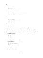
1 Introduction
The language described in this report is based upon PL360 by N. Wirth [1]. As far as the hardware allows,
the language follows the same conventions as PL360. The short address length is exploited by using the first
sector of the machine in a similar way to the Program Reference Table of the B5500 (as will be explained
in more detail later).
This report is an attempt to combine (a) a manual for users (b) a description of an Algol-like assembler
for other interested parties, and (c) a compiler-writer’s description of the language and compiler to assist
in future enhancements to the system. Clearly three reports should have been written but the author hopes
that this will be adequate.
It must be emphasized that this language is no substitute for Fortran or Algol 60, but rather a more
convenient and flexible system for writing large machine-code programs. The main advantage over DAP,
the assembler for the DDP-516, is that program texts are largely self-documenting due to their Algol-like
structure.
The author would like to thank all those who have contributed to the design and implementation of the
system, namely Miss Elizabeth Giles for preparing the compiler text, to D.A. Bell who wrote the compiler
in its own language and to G. Alway, F.G.Duncan, R. Scowen, P. Wilkinson and M. Woodger all of whom
made many suggestions and criticisms on the basis of the author’s rough notes.
The work described in this paper was carried out as part of the research work of the National Physical
Laboratory.
2 What is an Algol-like assembly language
The basic idea of PL516 is to provide a facility for writing machine-code which makes the program text
look superficially like Algol. This can be done by separating the features of Algol 60 into two classes.
Firstly those which require no subroutines to implement them in the running program. These can be
implemented in PL516. For instance, identifiers for naming locations in store. Six characters are significant
in this compiler and additional characters can be added although they are ignored. This gives substantially
greater flexibility over DAP which only allows up to four characters in an identifier.
Secondly are those features which require subroutines in the program because the machine cannot
implement the feature in a straightforward manner. Dynamic storage allocation is such a facility. If the
machine had hardware for storage allocation like the B5500 then this would be a feature of the assembler.
Since there are no hardware facilities for floating point on the PPD-516, this language uses integers only.
2
Hence the following table can be constructed:
PL516 contains: identifiers, type-checking, scope to identifiers, procedures, compound statements, conditional statements, simple for loops.
PL516 does not contain: dynamic storage allocation, multi-dimensional arrays, more than one parameter
to procedures, call by name, expressions involving temporary working store, real variables.
In addition to the Algol-like facilities of the assembler, one can write ordinary machine code (for
communicating with peripherals, for instance), refer to constants by identifiers to improve the legibility of
the program, and initialise the values of an array (possible because fixed storage is used).
Numerous examples of procedures and programs are given throughout this report and a glance at these
will illustrate many of the points made above. Those who prefer to learn by examples may like to start at
section 5.
3 The DDP-516
The assembler is, of course, a machine-dependent language. So to describe how the language is implemented
it is necessary to understand the addressing mechanism and instruction code. This is given in detail in [2, 3]
but this section is added to make the report as complete as possible.
The DDP-516 is a 16-bit machine with two main registers. The first register, called the A register, is the
main accumulator of the machine. The second is the X register which is the index register. The X register
is also word 0 of the machine.
There are four classes of instructions as follows:
Generic instructions. These addressless instructions usually operate on the contents of the accumulator.
An example is TCA (Twos Complement Accumulator) which negates A as a 16-bit signed integer.
In referring to machine instructions in this report, the DAP conventions will be used (see [3]).
Shift instructions. These instructions have a six-bit field giving the two’s complement of the shift required.
Double length shifting can be done using the B register. The B register is not directly accessible
by instructions and so will not be mentioned very much in this brief account. Twelve shift orders
are available in total from all possible combinations of left, right, logical and cyclic and arithmetic,
single and double length.
Input-output instructions. These instructions have a 10-bit address field divided between the device
function code and the device address.
Memory reference instructions. (for DXA mode machines having 16K only). These instructions are
very important since they determine the addressing structure of the machine. The operation code
is 4-bits giving a basic repertoire of instructions for adding, subtracting etc, the accumulator to the
word accessed. The remaining 12 bits of the instruction are divided into 3 one-bit flags and a 9-bit
address. One flag is the ‘this sector bit’. If this is set, then the full 14 bit address is formed by taking
the most significant five bits from the current instruction address. This means that the machine is
sectored into blocks of 512 words so that one can either address the sector one’s instructions are in
or sector 0, the first sector of the machine.
The other two flag bits are the ‘indirect’ bit and the ‘index’ bit which, together with the 14 bit address,
gives one machine word. If the ‘index’ bit is set then the current contents of the X register are added
to the 14 bit address constructed from the instruction. After this, the indirect bit is inspected. If it is
not set then the address of the operand has now been calculated. If the indirect bit is set, then the 14
bit address is used to load a 16 bit word which is interpreted as an address with indirect and index
bits. This process of indirection can be carried to arbitrary depth. To illustrate this, consider three
examples:
3
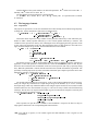
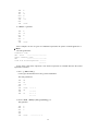
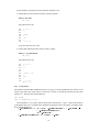
1. One of the memory reference instructions is a jump order JMP. Ordinarily in the assembler
jumps are within the current sector and so a direct jump can be made. However, jumps to labels
not in the current sector can be done by putting in sector 0 the 14 bit address of the label. Then
the jump is an indirect jump i.e, with the indirect bit set in the instruction. The instruction
points to the word in sector 0. This word in sector 0 does not have the indirect bit set (nor index
bit) so the jump is effected to the 14 bit address given by this word.
This can be represented diagrammatically thus:
JMP ’indirect’ ->
| | |........
->
........
word in sector 0
location of label anywhere in store
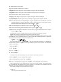
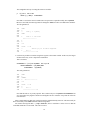
2. One of the memory reference instructions loads the accumulator (LDA). How does one use the
addressing to load the ith element of an array b into the accumulator? For each array in the
assembler there is an ‘array word’ which has the 14 bit address of the zero-th element of the
array together with the index bit set. To load b[i] we do:
LDX I which loads the index register
LDA ’indirect’ ->
| |*|........
’array word’ with index bit set in
current sector or sector 0
->
........
b[0]
I
........
b[i] anywhere in store.
In the assembler the array word is always directly addressable from the instruction and so is
either in the current sector or in sector 0.
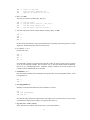
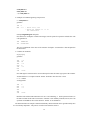
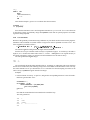
3. The third example illustrates how the addressing is used to implement switches. Switches are
simpler than in Algol 60 in that each switch element is a label. The ‘switch word’ s has both
the index and the indirect bit set, so diagrammatically this is:
LDX I which loads X register as with arrays
JMP ’indirect’ ->
|*|*|........
’array word’ in
current sector or sector 0
->
........
s[0]
I
| | |........
s[i] address of ith label
->
label corresponding to ith
element of switch
So one level of indirection plus one level with both indirection and indexing is used to do the
required jump.
Control instructions. Apart from the unconditional jump other orders exist to transfer program control.
Generic control instructions. Instructions in this category see if a particular condition is true. If it
is, the next instruction is skipped over. So it is usual to place unconditional jumps after such
instructions, the jump being to code which deals with the case where the condition is false. An
example of such an instruction is SPL which skips the next instruction if the accumulator is
positive. Hence the instructions SPL followed by TCA takes the absolute value of the contents
of the accumulator.
Subroutine jump instruction. This instruction, JST, is a memory reference instruction and so the
address is calculated in the way described above. In this address is placed one more than the
address of the JST instruction itself. Control then passes to the next word in the computer store.
4
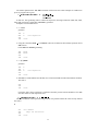
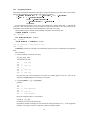
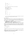
In the assembled code of PL516 the addresses of procedures are kept in sector 0, and so one
has diagrammatically:
JST ’indirect’ ->
| | |........
address word of procedure in sector 0
->
| | |........ return address planted here
.............
............. code of procedure
JMP ’indirect’ to return address above
As illustrated, the return is done by doing an indirect jump to the return address which is planted
by the JST instruction.
Note that code cannot be pure on this machine since the return addresses must be stored with
the code.
Increment in store instruction. This instruction IRS, is also a memory reference instruction. the
operand is incremented by one in the store without affecting the accumulator. If the result of
this incrementing is to give zero, then the next instruction is skipped. Frequently one knows
from the logic of the program that the result can never be zero so no jump order or special
coding is placed after the IRS (beware!). The instruction is very useful for loop control, but the
counting goes from ,n; :: , 1. The jump after the IRS returns control to the beginning of the
loop.
The compare instruction. The last instruction CAS is also a memory reference instruction which
does not alter the accumulator. It is a control instruction for comparing the accumulator with
the operand. If the accumulator > operand the next instruction is executed, with equality
one instruction is skipped and with accumulator < operand two instructions are skipped. By
inserting appropriate jump instructions after the CAS all various inequalities can be tested for.
4 The language
PL516 will be described in a manner similar to the Algol 60 report [4]. Each feature of the language is given
by a formal syntactic description using a variant of the Backus-Naur notation. For those not familiar with
this, a verbal explanation is also given as well as many examples. The semantics are given by explaining
the code generated by the compiler. This is given in DAP, so the reader is referred to [2, 3] or Section 3 of
this report for a shorter account.
4.1
The syntax notation
The notation used is the Backus-Naur form with a number of additions to shorten the description introduced
by F.G. Duncan [5]. The cross-reference technique of Coulouris [6] is also used.
The first addition is to abbreviate the fact that a symbol may or may not occur. For instance
< a >::= < b > < c >
means
< a >::=< c > j < b >< c >
That is an < a > is a < c >, or a < b > followed by a < c >.
To assist in searching for the appropriate syntax rule, these rules are all numbered and each reference
to a rule is preceded by the number. Hence the rule above might be
< 1:3a >::= f< 1:2b >g < 4:8c >
Symbols of the language itself are written in bold or the symbol itself like the Algol 60 Report. A
complete list of the symbols is given in Appendix A. Syntax rule n:r is to be found in section 4.2.n.
5
Another addition to the syntax notation is to deal with repetitions < a >1 means one or more < a >’s.
Similarly < a >0 means zero or more < a >’s.
The last addition is to deal with lists in a compact manner.
<< a > list < b >> means < a ><< b >< a >>0 . Usually < b > is a separator such as a comma
or semicolon.
4.2
4.2.1
The language elements
Expressions
The purpose of expressions is to do some calculation from values already stored without using temporary
working store. All the calculation is done in the accumulator alone.
< 1:0expression >::= < 1:3unary operator >0 < 1:1term >
<< 1:4binary operator >< 1:2cell >
j< 1:5shift operator >< 4:0constant >>0
This means that an expression is any number of unary operators followed by a term followed by any
number of either a binary operator followed by a cell or a shift operator followed by a constant. The
evaluation of the expression is done by first evaluating the term, then applying the unary operators in the
reverse order to the appearance in the text, then applying the binary or shift operators in the order left to
right. Detailed examples are given later when the other terms have been defined.
< 1:1term >::= accumulator j
< 1:2cell >j
(< 1:0expression >) j
< 9:0procedure call >j
zero j
codeword < 11:5type identifier >j
if < 3:0condition > then < 1:0expression > else < 1:0expression >
The purpose of term is to do the initial loading operation on the accumulator before the operators are
applied to it. This load operation is omitted in the case where the accumulator symbol is read. By this
means the current contents of the accumulator can be used in an expression (but only by explicitly stating
this). When the symbol zero is written, then the instruction CRA (CleaR Accumulator) is generated. The
possibility of nesting expressions by means of brackets means that quite complex expressions can be done
although no temporary working store is used.
< 1:2cell >::= < 14:1integer identifier >j
ind < 14:1integer identifier >j
< 14:3array identifier >< 2:0subscript >j
< 4:0constant >
All variables in this language are 16-bit integers. A cell is such an integer addressed in one of four ways.
Firstly, the integer may be declared as a simple integer and given an identifier, say i1 or int2. Secondly
the simple integer ‘addi’ may contain the address of the integer required. In this case access must be made
with the indirect bit set in the instruction (see page 3). The case of arrays is dealt with when describing
subscripts. The last case is an explicit constant which is given a location by the compiler as necessary and
accessed directly like an ordinary integer.
< 1:3unary operator >::= addc j inc j neg j
setsignplus j setsignminus j not j
changesign j copysignandsetplus j icleft j
cleft j swop j icright j
abs j abug
These operators act upon the current contents of the accumulator. Except for the last two, they are
single generic instructions. The corresponding DAP instructions are:
addc ACA add the C register (a 1 bit overflow register and shift indicator) to the A register (ie, the
accumulator)
6
inc AOA add one to the A register
neg TCA negate the constants of the A register
setsignplus SSP clears the sign bit of the accumulator leaving the other bits unchanged
setsignminus SSM sets the sign bit of the accumulator leaving the other bits unchanged
not CMA all the bits in the A register are changed
changesign CHS change the sign bit of the A register leaving the other bits unchanged
copysignandsetplus CSA the sign bit of A is put into the C register, and the sign bit is cleared
icleft ICL This instruction is for manipulating the A register regarded as two 8 bit characters. The most
significant character is moved to the bottom of the A register and the top of the register cleared.
Instruction stands for Interchange and Clear Left, ie (x; y) ! (0; y)
cleft ICA Interchange the two characters in the A register ie (x; y) ! (y; x)
swop CAR Clear the least significant character in the A register ie (x; y) ! (x; 0)
icright ICR The least significant character is moved up in the A register and the bottom of the A register
cleared, ie (x; y) ! (y; 0)
The penultimate operator is slightly different in that two instructions are generated namely:
abs SPL TCA. This gives the absolute value of the A register (see page 4).
abug is a compiler controlled diagnostic facility. When the appropriate compiling options are set the
instruction JST *’776 is generated, otherwise no code is output. The compiling options are explained in
the programming notes for the version of the compiler in use.
< 1:2term >::= + j , j and j
nev j j = j mod
It has been pointed out in < 1:0expression > that ‘term’ caused the accumulator to be loaded, after
which the unary operators are applied. At this stage the binary operators can be invoked. The instructions
to do this are as follows:
+ ADD < operand >
- SUB < operand >
and ANA < operand >
nev ERA < operand >
The last three are somewhat different since more than one instruction is generated:
* MPY < operand > LLS 15 (long left shift 15 places)
/ LRS 15 (long right shift 15 places) DIV < operand >
mod LRS 15 (long right shift 15 places) DIV < operand > IAB (interchange A and B registers)
These instructions are the ones produced by the current version of the compiler. Since MPY and DIV
are not available on some machines, they must be replaced by a subroutine call or otherwise removed
altogether. The compiler itself does not use these instructions.
Some realistic examples of expressions can now be given.
1. abs a + b
This will generate the machine code:
7
LDA
SPL
TCA
A
since a is the term
after the unary operators are
applied, two instructions for abs
2. not (a + b) and c
The term (a+b) must be evaluated first, this gives:
LDA
ADD
CMA
ANA
A
B
C
form
from
from
from
the
the
the
the
term a
binary operator + and cell b
unary operator not
binary operator and cell c
3. The same expression as above with the brackets missing: not a + b and c
LDA
CMA
ADD
ANA
A
B
C
In other words, the brackets in expressions determine the positioning of the unary operators. Unlike
Algol 60 or Fortran all operators have the same priority.
4. For example: a + b * c
generates the code:
LDA
ADD
MPY
LLS
A
B
C
15
since the binary operators are applied in the order left to right. No priority can be given to operators
as can be seen from this example. This is because once ‘a’ has been loaded into the accumulator
there is no way of multiplying b and c. Temporary storage would have to be used to preserve the
contents of the accumulator but this is excluded.
5. accumulator + b * c
Here the current constants of the accumulator is being referred to so no load operation is done, so the
code generated is
ADD
SUB
B
C
6. not setsignminus zero
Instead of a load operation zero clears the accumulator so we have
CRA
SSM from setsignminus
CMA from not
Note that the unary operators are applied in the order right to left. The effect of this is to leave in the
accumulator the largest positive integer (zero sign bit, the rest all 1’s).
7. neg (abs (not a + indb)/c) mod d
Just to illustrate how complex expressions can be. The code generated is
8
LDA
CMA
ADD*
SPL
TCA
LRS
DIV
TCA
LRS
DIV
IAB
A
B
since the innermost term is evaluated first
from the not
* means set the indirect bit in instruction
now abs (two instructions)
15
C the /c completes the outermost term
so now apply neg
15
D
finally the mod d
Expressions involving constants, arrays, procedure calls, conditions and type identifiers will be illustrated when the appropriate syntax has been described.
< 1:5shift operator >::= singlerightlogical j singleleftlogical j
singlerightarithmetic j singleleftarithmetic j
singlerightcyclic j singleleftcyclic j
doublerightlogical j doubleleftlogical j
doublerightarithmetic j doubleleftarithmetic j
doublerightcyclic j doubleleftcyclic j
The number following the shift operator is two’s complemented and truncated to 6 bits and then placed
in the appropriate instruction. It is only possible to shift by a constant amount, since the amount is placed
in the instruction by the compiler.
The above operators generate the shift instruction (in the order above): LGR, LGL, ARS, ALS, ARR,
ALR, LRL, LLL, LRS, LLS, LLR and LLR. The double length shifts regard the B register as an extension
to the bottom of the A register.
The hardware representation of the shifts (see Appendix A) uses five characters to increase program
legibility.
4.2.2
Arrays and subscripting
One dimensional arrays of integers are part of the assembly language. Because of the fixed storage lay-out,
the size of the array must be given to the compiler. Array elements are accessed in the manner described
on page 4.
The syntax of the subscripting mechanism is:
< 2:0subscript >::= [<< 14:1integer identifier >j
< 4:0constant >j
xsymbol >]
The purpose of the subscript is the load the X register, so that the appropriate element of the array can
be accessed. In the first case the integer is loaded into the register, in the second case the constant is loaded.
In the final case no LDX instruction is generated. This is used if the X register already contains the
required value. It will be noted that complex subscript expressions are not allowed. This is a consequence
of the fact that no arithmetic operations can be performed in the X register itself. When more complex
expressions are required, the relevant calculation must be done in the accumulator and the result assigned
to word 0 of the machine (which is the X register). This will be explained in section 4.5.2.
Some examples of expressions involving array accessing can now be given.
1. ar1[i] + ar[j] - ar[k]
Each subscript gives a LDX operation so the code for this is
LDX
LDA*
LDX
ADD*
LDX
SUB*
I
AR1
J
AR
K
AR
9
Note the indirect addressing via the array word in all the instructions accessing the array elements.
2. not(ar[i] and ar1[xsymbol]
The first subscript loads the X register with i so that the second array element accessed is ar1[i]. The
code generated is:
LDX
LDA*
ANA*
CMA
I
AR
AR1
3. negabs(ar[i] * ar1[xsymbol]) / ar2[j]
This generates the code:
LDX
LDA*
MPY*
LLS
SPL
TCA
TCA
LDX
LRS
DIV*
4.2.3
I
AR
AR1
15
which loads the first array element
multiplying by the second array element
from abs
from neg
J
15
AR2
note the LDX operation is performed before any of
the divide operation
Conditions
There are no boolean variables in PL516. Apart from ordinary jump instructions control is effected by
means of conditions. This is done by making use of the test orders which skip one instruction if the
condition is true. The instruction which may be skipped over is a jump to the code which deals with the
case when the condition is false. This jump order is generated automatically by the compiler and in the
examples which follow is written as JMP false.
< 3:0condition >::= < 1:0expression >< 3:3relational operator >< 1:2cell >j
< 1:0expression >< 3:2accumulator condition >j
< 9:1conditional procedure call >j
< 3:1condition operator >
The first type of condition uses the CAS instruction (see page pagerefsec354) to compare the current
contents of the accumulator (set by expression) with the word in store determined by cell.
The second case is where the expression sets the accumulator and is tested by a single instruction.
Thirdly, a procedure can be a conditional procedure. In this case the procedure may return control in
the ordinary position if the condition is false, or one instruction further on if the condition is true. This will
be explained in more detail when procedure calls are dealt with in section 4.2.9.
The last case is the simplest, the syntax of which is:
< 3:1conditional operator >::= sense1 j sense2 j
sense3 j sense4 j
anykey j nokey j
cset j notc
There are four sense keys on the machine, numbered 1 to 4. The instruction SS1 skips the next order if
sense key one is set. So the condition operator sense1 generates the code:
SS1
JMP
false
and similarly with sense2, sense3 and sense4. anykey gives SSS, nokey gives SSR, cset gives SSC
and notc gives SRC.
10
The address planted in the JMP false instruction will become clear when examples of conditions in
pieces of program can be given.
< 3:2accumulator condition >::= zero j plus j
nonzero j odd j
even j minus
In this case, after generating code to evaluate the expression, the single instruction (SZE, SPL, SNZ,
SLN, SMI, respectively) followed by JMP false is generated.
Examples of such conditions are:
1. a + b zero
generates:
LDA
ADD
SZE
JMP
A
B
from expression
false
2. Using the convention true =
and bool2 as:
,1 and false= 0 then one would write the booleans expression bool1
bool1 and bool2 nonzero generating:
LDA
ANA
SNZ
JMP
BOOL1
BOOL2
false
3. a + b[i] minus
generates:
LDA
LDX
ADD*
SMI
JMP
A
I
B
from expression
false
4. zero zero is a valid condition since the first zero is from term and the second an accumulator condition.
The code is:
CRA
SZE
JMP
false
Clearly the skip is always performed. Confusion is not likely to arise from the double use of A zero
since the context is clear in practical cases.
< 3:3relational operator >::= =j6=j>j<jj
After the evaluation of the expression and generation of a possible LDX if the cell is an array element
the code is:
=
CAS
SKP
SKP
JMP
cell address
skips one instruction
false
11
6=
CAS
SKP
JMP
cell address
skips one instruction
false
CAS
JMP
NOP
JMP
cell address
*+3
this means jump forward three places
dummy instruction
false
CAS
NOP
SKP
JMP
cell address
dummy instruction
CAS
JMP
NOP
cell address
false
>
false
The details of these instructions need not, of course, be remembered. The effect of the code is clear,
control passes according to the usual interpretation of the operators leaving the value of the expression in
the accumulator. It is worth remembering that using relational operators generates 3 or 4 instructions, but
has the advantage that the accumulator is compared with a word in store without disturbing the accumulator.
1. accumulator = a generates
CAS
SKP
SKP
JMP
A
false
Note there is no code from the expression.
2. a + b 6= c[i] generates
LDA
ADD
LDX
CAS*
SKP
JMP
A
B
I
C
from expression
from c[i]
false
3. a / b[i] > c[xsymbol] generates
12
LDA
LDX
LRS
DIV*
CAS*
JMP
NOP
JMP
A
I
15
B
C
*+3
false
4. a mod b < c generates
LDA
LRS
DIV
IAB
CAS
NOP
JMP
A
15
B
C
false
Some examples can now be given of conditional expressions the syntax of which appeared in
1:1term >.
The code generated is:
<
<condition code>
JMP
false
-------------------> a
<extra condition code>
JMP
-------------------> b
<code from second expression> a <---b <----
So the effect is that if the expression is true the first expression is evaluated otherwise the second
expression is executed.
1. if xx > yy then xx else yy
Code to give the maximum of xx and yy in the accumulator.
The code generated is:
LDA
CAS
JMP
NOP
JMP
LDA
JMP
LDA
XX
YY
*+3
false
XX
YY
----> a
----> b
<---- a
<---- b
2. if a+b=c if d 6= e then f[-6] else g[8] else neg (y+z)
This generates:
LDA
ADD
CAS
SKP
SKP
JMP
A
B
C
false
-----------> a
13
LDA
CAS
SKP
JMP
LDX
LDA*
JMP
LDX
LDA*
JMP
LDA
ADD
TCA
A
E
false
=-6
F
=8
G
Y
Z
-----> b
-----> c
b<----c<-------->d
a<------------
d<------
4.2.4
Constants
Facilities for constants in the assembler are somewhat different from Algol 60. There is no ‘literal’ facility
in the instruction set for loading constants into the accumulator. Hence at binary machine-code level there
is no distinction between constants and ordinary integers. In PL516 however, there are three types of
constants. Firstly there are the explicit constants, a string of digits as in Algol 60. Secondly there is a type
of entity called constant. This is like an ordinary integer except that an initial value is given to it and the
assembler checks (as far as possible) that no assignment is made to it. Such constants are referred to by
their identifier. The third type of constant, called a compile constant, is also referred to by an identifier.
This, however, is not given any storage in the running program until it is referred to in a context which
requires that it should be given storage. The significance of this will become clear when examples of the
use of constants in complete programs is given.
The purpose of giving constants identifiers is to improve program legibility and yet preserve the static
nature of the constant in the program text. Explicit constants should be used very rarely since altering
one declaration of a constant is substantially easier than altering several occurences of the explicit constant
appearing throughout the program text.
< 4:0constant >::= < 14:4constant identifier >j
< 14:5compile constant identifier >j
< 4:1number >j
charsymbol < string character >< string character >j
addressoffindgfindexg < 11:5type identifier >j
< 4:0constant >; < 4:0constant >
< 4:1number >::= f,g < octalsymbol < octal sequence >j
< digit >1 >
An octal sequence is of course, a sequence of one or more digits excluding 8 and 9. The minus sign
has the usual interpretation, but note that it is not an operator. The unary operator written as - in Algol 60
is neg in PL516 (see < 1:3unary operator >). The accumulator can be regarded as two 8 bit characters
so there is a facility to set constants appropriately. A string character is a space or a Teletype 33 graphic
character and so excludes control characters.
Indirect and indexed addressing is ordinarily dealt with for the user through the use of arrays (and the
layout to be explained later). However 16 bit addresses with the index or indirect bits set can be formed by
using the addressof type of constant. The form of the address is given in section 4.2.11.
The form of constant appearing in angle brackets (shown as ; ) is to allow each half of the word
to be set separately by the appropriate constant. In the example given below, -8 is placed in the most
significant 8 bits and octal 70 in the lower 8 bits.
1. Examples of constants
noinputs
692
-84
14
octalsymbol 123
charsymbol AB
<-8, octalsymbol 70 >
2. Examples of constants appearing in expressions
a + octalsymbol 77
generates
LDA
ADD
A
=’77
’ means octal, the
= means put address of ’77 in
the instruction
interrupt singleleftlogical clockpulse
Note in this case ‘clockpulse’ cannot be an integer, since the syntax for expression excludes this. The
code generated is
LDA
LGL
INTERRUPT
CLOCKPULSE
The two’s complement of the value of the constant ‘clockpulse’ is truncated to 6 bits and placed in
the instruction.
3. Constants in conditions
ar[-6] > b[-2]
generates
LDX
LDA*
LDX
CAS*
JMP
NOP
JMP
=-6
AR
=-2
B
*+3
false
Note that negative constants can be out into subscripts because the minus sign is part of the constant.
Assume that there is a compile constant ‘minus1’ declared to have the value -1 then
a + -1 = minus1
would generate
LDA
ADD
CAS
SKP
SKP
JMP
A
=-1
=-1
false
Both the CAS and the ADD instruction refer to a word containing -1. Such repeated references to
the same constant use the same word in store. If minus1 was an ordinary constant, however, the CAS
operation would address the word set aside for ‘minus1’ on its declaration.
The distinction between compile constants and ordinary named constants can be ignored initially since
it is of secondary importance. The point is covered in more detail in section 5.
15
4.2.5
Assignment statement
The purpose of assignment statements is that same as in Algol 60, namely to give new values to the variables
listed on the left-hand side of the statement. The syntax is as follows:
< 5:0assignment statement >::= << 5:1lhs > list <; >> < 1:0expression >
< 5:1lhs >::= < 14:1integer identifier >j
findg < 14:1integer identifier >j
< 14:3array identifier >< 2:0subscript >j
accumulator
So an assignment statement is one or more ‘lhs’s separated by commas followed by
and then the
expression. The code generated is to first evaluate the expression and then to store the contents of the
accumulator to the variables listed in the left-hand side in the order left to right.
Various distinct types of element on the left hand side produce the following code:
< integer identifier > produces:
STA
<integer>
ind < integer
STA*
identifier > produces:
<integer>
< array identifier >< subscript > produces:
code for subscript as described in 4.2.2
STA* <array>
accumulator produces no code and so is included if the expression is to be evaluated but no assignment
made.
Some examples:
1. Zeroise a number of elements of an array
ar[i], a[j], a[k] zero
This generates the code
CRA
LDX
STA*
LDX
STA*
LDX
STA*
from zero
I
A
J
A
K
A
from a[i]
from a[j]
from a[k]
Note that the order of the assignment is the order the variables appear in the text. This can be
important if xsymbol appears as a subscript, for instance.
2. ar[i], b[xysymbol]
generates
LDX
LDA*
ADD*
LDX
STA*
STA*
J
C
B
I
A
B
c[j] + b[xysymbol]
from expression
from a[i]
from b[xsymbol]
Hence the assignment above is equivalent to
ar[i], b[i]
c[j] + b[j]
but requires two fewer LDX instructions.
Programmers familiar with Algol 60 will no doubt be annoyed with the use of ‘,’ in the assignment
statement. The purpose of this is to make the compiler somewhat simpler.
16
3. To add one to the current contents of the accumulator one writes:
accumulator accumulator + 1
which generates the single instruction
ADD
=1
4. ind addv, i, j
generates
LDA
ADD
STA*
STA
STA
i+j
I
J from expression
ADDV
I
J
5. How does one write the equivalent of the Algol 60
a := b[i+j] ?
Clearly the X register must be loaded with i+j. The X register is word 0 of the machine, so the
assembler has a declaration set up for the integer x, which is given the address 0. So the above can
be written:
x
a
i + j;
b[xsymbol]
This generates the code
LDA
ADD
STA
LDA*
STA
I
J
0
B
A
To summarise, the facility provided by assignment statements in PL516 is very similar to that of Algol
60.
4.2.6
Statements using conditions
One of the distinguishing features of Algol 60 over Fortran is that fewer labels are required. This is because
flow of control can be expressed via conditional statements and for loops. This feature of Algol 60 is
present in PL516. Three forms of conditional control statements are available.
< 6:0if statement >::= if < 3:0condition > then < 10:0statement >
else < 10:0statement >
The effect of this statement is similar to the construction in Algol. If the condition is true the the first
statement is executed otherwise the second statement is executed. Representing the flow of control with
jumps by arrows, the code generated is as follows:
<condition code>
JMP false
-------------> a
<extra condition code>
<code from first statement>
JMP
-------------> b
<code from second statement> a<-----b<------
Examples can be given using assignment statements as statements.
17
1. if a zero then
a
b+c
else
b c+d
This generates the code
LDA
SZE
JMP
LDA
ADD
STA
JMP
LDA
ADD
STA
A
false
B
C
A
C
D
B
-------------> a
-------------> b
a<------
b<------
2. Add 3 to a[i] if a[i] is even, otherwise subtract 6 from a[i].
if a[i] even then
a[xsymbol]
else a[xsymbol]
accumulator + 3
accumulator - 6
Note the use of xsymbol and accumulator which reduces the size of code generated, which is:
LDX
LDA*
SLZ
JMP
ADD
STA*
JMP
SUB
STA*
I
A
false
=+3
A
=+6
A
-------------> a
-------------> b
a<-----b<------
3. In the above example two STA* A instructions are generated which would not be produced if it were
hand coded. However this can be avoided by writing:
if a[i] even then
accumulator accumulator + 3
else accumulator accumulator - 6;
a[xsymbol] accumulator
Which generates
LDX
LDA*
SLZ
JMP
ADD
JMP
SUB
STA*
I
A
false
=+3
=+6
A
-------------> a
-------------> b
a<-----b<------
18
It must be remembered that repeated use of xsymbol and accumulator especially over a number of
statements, makes the program less clear, since the reader must scan the text backwards to work out
the value of the X or A register.
4. In fact the above example can be more elegantly coded using a conditional expression. For instance
a[xsymbol]
if a[i] even then accumulator + 3 else accumulator - 6;
This produces the same machine code as the previous example.
5. There are no boolean variables, so integers must be used instead. The convention 0 = false and -1 =
true means that and and nev have the usual meaning.
Hence the Algol 60 statement
if a and b then
c := ar[i]
else
d := ar[j];
would be written in assembly code as
if a and b nonzero then
c ar[i]
else
d ar[j];
This generates the code
LDA
ANA
SNZ
JMP
LDX
LDA*
STA
JMP
LDX
LDA*
STA
A
B
false
I
AR
C
J
AR
D
-------------> a
-------------> b
a<------
b<------
Note that if statements always have an else. The reason for this is to avoid the ambiguity that existed
in the original Algol 60 report[4]. The revised report overcame this by making the syntax more
complex. This was not thought appropriate in this case, since being able to add a new statement type
would not be so easy. If no else is required then a when statement is written.
< 6:0if statement >::= when < 3:0condition > then < 10:0statement >
The machine code generated for this is:
<condition code>
JMP false
-------------> a
<extra condition code>
<code from statement>
a<------
19
1. when xx y then
accumulator y;
maxxy accumulator
Note that the A register is either set with xx by the condition or by y from the first assignment
statement.
This generates the code
LDA
CAS
JMP
NOP
LDA
STA
XX
Y
false
-------------> a
Y
MAXXY
a<------
2. Load into the accumulator the sense key reading as a binary number.
accumulator zero;
when sense1 then
accumulator
when sense2 then
accumulator
when sense3 then
accumulator
when sense4 then
accumulator
accumulator + 1;
accumulator + 2;
accumulator + 4;
accumulator + 8;
Not surprisingly the accumulator symbol is a single character on the Teletype representation (see
Appendix A). The code generated for all this is
CRA
SS1
JMP
ADD
SS2
JMP
ADD
SS3
JMP
ADD
SS4
JMP
ADD
false
=+1
( =+1 )
false
=+2
( =+1 )
false
=+4
( =+1 )
false
=+8
( =+1 )
Such repeated use of the accumulator symbol makes this one of the few cases when the DAP is
shorter to write than PL516.
The last form of statement using conditions is the while statement - a surprising omission from Algol
60. The syntax is:
< 6:0while statement >::= while < 3:0condition > do < 10:0statement >
The code generated is:
<condition code>
b<----JMP false
-------------> a
<extra condition code>
<code from statement>
JMP
-------------> b
a<------
20
So the statement is repeatedly executed while the condition is true.
1. Find the first non-zero element of an array form a[i] onwards
while a[i] zero then
i i + 1;
This generates the code
LDX
LDA*
SZE
JMP
LDA
ADD
STA
JMP
I a<----A
false
I
=+1
I
------>a
So a[i] now has a non-zero value.
2. Find the first differing elements of the two arrays a and b
while a[i] = b[xsymbol] then
i i + 1;
This generates the code
LDX
LDA*
CAS*
SKP
SKP
JMP
LDA
ADD
STA
JMP
4.2.7
I a<----A
B
false --->b
I
=+1
I
------>a
b<---------
Loop control
The machine instruction IRS (IncRement in Store, see page 5) is clearly intended for loop control. If one
wishes to go round a loop 3 times, then a word in store ‘COUNT’ is used for this which is given the value
initially of -3. The loop control is then done by:
IRS
JMP
COUNT
<to beginning of loop>
This mechanism is very crude in that one must always increment by +1 up to -1 and one must always
go through the loop once. Nevertheless this mechanism is adequate for the vast majority of ordinary loops.
So it is adopted for PL516.
< 7:0for statement >::= for < findg < 14:1integer identifier > < 1:0expression >j
< 7:1xassignment statement >>
do < 10:0statement >
< 7:1xassignment statement >::= xsymbol < 1:2cell >
21
A special case is where the count is word 0 of the machine. This is the X register which allows indexing
to be performed efficiently. In this case, loop control does not use the accumulator since the initial loading
of the X register can be done by an LDX operation. This is reflected in the syntax by the option using the
‘xassignment statement’.
The code generated is as follows:
Without the xassignment statement. STA
CONTROL
a<--------------<code from statement>
IRS CONTROL
JMP
----------------->a
The STA and IRS instructions have the indirect bit set if the integer control variable has ind in front
of it.
with the xassignment statement. LDX
<address of cell>
a<--------------<code from statement>
IRS 0
JMP
----------------->a
One important consequence of this method of loop control is that it is convenient if array elements are
addressed for ,n, to -2, -1. Rather than produce arrays in either order (as in DAP) for consistency all arrays
are addressed from -(size of array in words) to -1. This means that control variables have the opposite sign
to what would be usual in Algol 60 and the scanning is in the opposite direction (although in the direction
of increasing address).
Examples:
1. Add two vectors element by element putting the result in a third vector. Assume that the number of
words in the vectors is -size.
This simple loop can be coded using the X register as the control variable thus:
for xsymbol size do
a[xsymbol] b[xsymbol] + c[xsymbol]
This generates the machine code
LDX
LDA*
ADD*
STA*
IRS
JMP
SIZE
a<--------------B
C
A
0
----------------->a
Note that size is negative, and that -30 (for instance) could have been written instead of size. This
would be undesirable since changing the program for a different size of arrays would require going
through the entire program text altering all the constants.
2. Find the largest element of an array.
This might be written in Algol 60 thus:
j := c[1]; for i := 2 step 1 until size do
if c[i] > j then j := c[i]
22
The straightforward way of coding this in PL516 would be
j
c[1]; for i inc size do
when c[i] > j then j accumulator
Note that i is used as the control variable since an expression is required initially (since xsymbol
inc size is not valid). the if in Algol must be changed to when since there is no else in the statement.
Th code generated is
LDX
LDA*
STA
LDA
AOA
STA
SIZE
C
J
SIZE
LDX
CAS*
JMP
NOP
JMP
STA
IRS
JMP
I
C
*+3
I
from j <- c[size]
from i <- inc size
a<---------------
false --->b
J
since c[i] is in the A register
I
b<-------------------->a
3. It is however possible to code this using the X register as the control variable. In this case, the largest
element of the array so far is kept in the accumulator.
This is written as
accumulator c[size]; for xsymbol inc sizep1 do
when accumulator < c[xsymbol] then
accumulator c[xsymbol]
The code generated is
LDX
LDA*
LDX
CAS*
JMP
NOP
JMP
LDA*
IRS
JMP
SIZE
C
SIZEP1
C
a<-------------*+3
false --->b
C
0
b<-------------------->a
Note that this code is very nearly optimal. This is achieved by use of xsymbol and accumulator but
as a consequence the program is much less intelligible. The new constant ‘sizep1’ has the value one
more than size.
More complex for loops that exist in Algol 60 must be coded differently in PL516. This can usually be
done conveniently with a while statement without using labels.
For instance the Algol 60 for i := j step k until n do, where n could have a value of zero so that the
controlled statement is not executed. This can be code as:
23
i j;
while i n do
begin
<controlled statement>;
i i+k
end
Note that the example 5 given in 4.2.5 could not have been written as
xsymbol i + j;
a
b[xsymbol]
Since the first statement is not a valid assignment statement as i+j is not a cell. So x is used when one
is using the X register as an ordinary integer but xsymbol is used when its special properties as an index
register are being exploited.
4.2.8
Goto statements
Because of the generality of statements using conditions very few labels need be written in most programs.
Statements can be lebelled in a similar manner to Algol 60 as will be explained in section 4.2.10. Two
forms of goto are provided as follows:
< 8:0goto statement >::= goto << 14:6label identifier >j
< 14:7switch identifier >< 2:0subscript >>
The statement goto ll would generate the single instruction JMP LL.
Switches are set up in a manner similar to arrays as explained on page 4. As with arrays, the index is
negative, so a 3 element switch have index values -3, -2 and -1. Although there is no logical necessity to
have them with negative values it is convenient for the mechanism to be the same as arrays.
The code generated from goto SS[i] is
LDX
JMP*
I
SS
The switch word SS has the index and indirect bit set. Assuming i is within range (this is not checked!)
the next level of indirection (after indexing) will give the 14 bit address of the label in the switch. The way
the switch elements are set up is described in 4.2.12. Note that since the subscripting of switches is the
same as arrays, xsymbol can appear instead of an integer.
Examples
1. Find an element of an array ‘a’ equal to i, and goto the corresponding element of a switch ‘branch’.
Otherwise goto the label ‘error’.
accumulator i;
for xsymbol size do
when accumulator = a[xsymbol] then
goto branch[xsymbol];
goto error
Note that the accumulator has been loaded with i outside the loop.
The code generated is
LDA
LDX
LDX
CAS*
SKP
I
SIZE
SIZEP1
A
a<--------------
24
SKP
JMP
JMP*
IRS
JMP
JMP
false --->b
BRANCH
0
b<-------------------->a
ERROR
2. There is no designational expressions in PL516, so that the Algol 60
goto if xx > 0 then ll else error1
must be written as
if xx > 0 then goto ll else goto error1
This generates the code
LDA
CAS
JMP
NOP
JMP
JMP
JMP
JMP
XX
=0
*+3
false
LL
ERROR1
--->b
--->a
b<--a<---
This is one of the few cases where PL516 generates code which is substantially worse than hand
coding. Note the non-executable jump round the ‘else statement’.
4.2.9
Procedure calls
There are four types of procedures in PL516. A procedure may expect a parameter and it may be a
‘conditional’ procedure. All four types exist but they may only be called in the appropriate context. All
procedures may leave a result in the accumulator. Procedure calls can occur in three different contexts. The
first is in < 1:1term > and the second < 3:0condition > which have been given. The last context occurs
in the next section as a statement. The syntax is:
< 9:0procedure call >::= < 14:1procedure identifier > f(< 1:0expression >)g
< 9:1conditional procedure call >::= < 9:0procedure call >
the second rule is written down separately to imply a check in the compiler that only conditional
procedures can be called in the context of a condition, and that they may not be called in the other
two contexts. Apart from being conditional a procedure may have one parameter. This parameter is
an expression which is evaluated before entering the procedure. Hence by analogue with Algol 60, one
value parameter is allowed in which case the value of the expression is in the accumulator on entry to the
procedure.
So the code generated is
{<code from expression>}
JST* <procedure>
The procedure call is always indirect since the address of the procedure is kept in sector 0 as explained
on page 4.
It is always assumed that procedures leave the A register set appropriately. So the same procedure can
be called in < term > (which is clearly expects this) or in < statement >. But if a procedure is an
accumulator procedure then on every call it must have a parameter.
Examples are given of each of the four types of procedure.
25
1. ‘readn’ is an ordinary procedure which reads a number off a given input device.
i, j, n
neg readn + 1
This generates the code
JST*
TCA
ADD
STA
STA
STA
READN
=+1
I
J
N
2. However readn could be called as a statement producing the single instruction JST* READN. This
would merely have the effect of skipping over one number on the input device (assuming the contents
of the accumulator was not used).
3. ‘square’ is procedure with one parameter which produces the square of the parameter as the result.
y 4 + 2y 2 + 6
can be evaluated by the expression
square(square(y)+1)+5
This generates the code
LDA
JST*
ADD
JST*
ADD
Y
SQUARE
=+1
SQUARE
=+5
4. In the version of the PL516 compiler in its own language there is an accumulator conditional
procedure ‘bsis’. This determines whether or not the current basic symbol is one of a number of
types, that is, unary operator, binary operator etc. This is done by searching a table from a position
depending on the particular type.
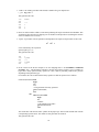
For instance, the code to deal with the binary operator or shifts in expression is as follows:
morebinorshift: if bsis then
begin
nbs;
cell;
<code generation for binary operators>
goto morebinorshift;
end
else
when bsis(shift) then
begin
nbs;
constant;
<code generation for shifts>
goto morebinorshifts
end;
The routine nbs reads the next basic symbol off the paper tape, and cell and constant deal with the
corresponding syntactic units. The details of code generation are omitted.
This generates the code
26
MOREBINORSHIFT
LDA BINARY
JST* BSIS
JMP false (to LDA SHIFT)
JST* NBS
JST* CELL
<code generation for binary operator>
JMP MOREBINORSHIFT
JMP
jump over else: never executed
LDA SHIFT
JST* BSIS
JMP false (to end)
JST* NBS
JST* CONSTANT
<code generation for shifts>
JMP MOREBINORSHIFTS
One can see from this how the compiler keeps scanning the text until a symbol which is not a binary
or shift is reached. The parameter to bsis is clearly necessary so that it is known which part of the
table to scan.
Thus conditional procedures in PL516 are very similar to boolean procedures of Algol 60.
4.2.10 Statements
Many of the types of statement have already been introduced. The complete list is as follows:
< 10:0statement >::= < 5:0assignment statement >j
< 6:0if statement >j
< 6:1when statement >j
< 6:2while statement >j
< 7:0for statement >j
< 7:1xassignment statement >j
< 8:0goto statement >j
< 9:0procedure call >j
< 14:6label identifier >:< 10:0statement >j
< 10:1null >j
< 10:2compound statement >j
< 11:0code statement >j
exittrue
exitfalse
sbug
< 10:1null >::=
< 10:2compound statement >::= begin << 10:0statement > list <; >> end
A compound statement is the same as in Algol 60, namely begin followed by a list of statement separated
by semicolons followed by end. The code generated is, of course, just the concatenation of the code from
the individual statements.
Most of the statements have already been explained, note that conditional procedures cannot be called
as statement.
Any statement can be labelled and within the scope of the label a goto statement can transfer control to
that point. Hence it is possible to jump into the middle of a for loop (NB not valid in Algol 60). The effect
of this would depend on the value of the control variable before executing the goto.
Code statement is dealt with in the next section; it merely provides a convenient method of writing
DAP-like instructions within the program.
The instructions exittrue and exitfalse provide a means of exit from a conditional procedure. Their use
other than inside a conditional procedure is regarded as an error by the compiler. The code generated for
exittrue is
27
IRS
JST*
<return address>
<return address>
and for exitfalse is
JST*
<return address>
So exitfalse is the ordinary return instruction, but exittrue increments the return address by one before
returning. (Note: the result can never be zero.) This corresponds to the expected action of conditional
procedure calls in conditions (see 4.2.3).
The last statement sbug is a diagnostic aid. It is either regarded as a dummy statement or as a call of a
procedure whose address word is placed in a fixed position octal 777 in sector 0. Hence the code generated
is:
JST*
’777
The procedure called in this way can be provided by the user, and can usefully print out the position of
its call, contents of the accumulator etc. Further details are given in the program notes for the version of
the compiler in use.
Examples
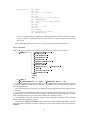
1. There is a conditional procedure in the PL516 compiler which is used to tell if a character is a letter.
The main coding of this procedure is:
when accumulator zsymbol then
when accumulator zsymbol then
exittrue
This produces the DAP
CAS
JMP
NOP
CAS
NOP
SKP
JMP
IRS
JMP*
ZSYMBOL
false
(to end)
ASYMBOL
false
(to end)
<return address>
<return address>
If the exittrue is not executed, then the ordinary exit is made from the procedure (which is exitfalse).
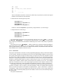
2. A single procedure deals with constants as defined in 4.2.4. The coding of this procedure can now
be followed:
if bs = charsymbol then
begin
value swop inchar;
value inchar+value;
nbs;
value zero
end else if numerical(bs) then
begin
number;
vadd zero
end else if bs = addsymbol then
28
begin
nbs;
if bs = indsymbol then
begin
value octalsymbol 100000;
nbs;
end else
value zero;
when bs = indexsymbol then
begin
value octalsymbol 40000;
nbs;
end;
typeident;
when add > octalsymbol 777 then
add - octalsymbol 1000 + sectno;
add
value value + add;
vadd zero;
end
else if letter(bs) then
begin
identifier;
if type = const then
begin
value getcode(add);
vadd add;
end else if type - compconst then
begin
value add;
vadd zero;
end
else
fail(notconst);
end
else
fail(badstart)
The code closely follows the syntactic definition. ‘nbs’ (next basic symbol) reads the next compound
symbol from the paper tape. ‘inchar’ reads a character. The coding sets the value of the constant
in ‘value’, and its address (if it has one) in ‘vadd’, otherwise ‘vadd’ is set to zero. If the constant
is a declared constant then ‘getcode’ is used to get the value of the constant from the code already
generated.
The generated code is not given, since it is straightforward. The example does illustrate the similarity
of the coding with Algol 60. Note that each compound statement can be studied in isolation, making
it easier to follow the overall structure. The coding is by no means optimal, the accumulator sysmbol
could be used in a number of places, but this would reduce the clarity of the procedure.
4.2.11 Code statement
Code statements provide a means of writing DAP-like machine code within a PL516 program. This is
certainly necessary for input-output instructions since they are not otherwise available. For completeness,
the full range of DAP instructions are available (but not the pseudo-instructions). Using these instructions
when it is possible to achieve the same effect with ordinary statements loses the point of PL516. For this
reason writing code statements should be kept to a minimum except where necessary or (as sometimes
happens) a code statement is clearer than the equivalent PL516 coding.
29
In keeping with the rest of the language, code statement are in free-format, and have the following
syntax.
< 11:0code statement >::= codesymbol << 11:1memory reference >j
< 11:2I=O or shift >j
< 11:3generic >>
< 11:1memory reference >::= < memory reference mnemonic >
< ind j index j bfindindex j; >< 11:4address field >
< 11:2I=O or shift >::=< I=O or shift mnemonic >; < 4:0constant >
< 11:3generic >::=< generic mnemonic >
< 11:4address field >::= < 11:5type identifier >j< 4:1number >j
< 4:1number >
< 11:5type identifier >::= < 14:1integer identifier >j
< 14:2procedure identifier >j
< 14:3array identifier >j
< 14:4constant identifier >j
< 14:6label identifier >j
< 14:7switch identifier >
Hence the syntax depends upon the type of mnemonic encountered. Naturally a generic mnemonic
completes the statement. For shift or input-output mnemonics a constant follows. Note that the constant
can be declared constant given an appropriate identifier. In the case of shift instructions, the constant is
negated and truncated to 6 bits before inserting in the instruction.
The memory reference instructions are more complex. The ind and index symbols cause the indirect
and index bits to be set in the instruction. The address field gives the other 10 bits of the instruction. In the
case where this is a number, the value of this is put in the instruction. In the final case of the star proceeding
a number, the current instruction address is added to the number and this inserted in the instruction. This
convention with numbers is identical to DAP.
The most important address field is a type identifier. In this case the 10 bits inserted in the instruction
are the short address of the appropriate variable. For integers and constants this is just the short address
of a word in store. For arrays and switches this is the address of the ‘array’ word. For procedures the
address is to the word in sector 0 giving the long address of the link (see page 4). For labels, the address
depends upon whether the label is global or local (see 4.1.12) for details. In the case of a global label the
address is to a word in sector 0 giving the full address of the label (as for procedures). But with local labels
the address gives the address of the labelled statement. No reference is possible to compile constants in
memory reference instruction. The reason for this is that the meaning would not be clear - is the value or
the address of the constant to be inserted in the instruction? For technical reasons the generic instruction
OTK must be written as codesymbol OTK,0.
Examples
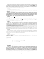
1. In the compiler, the instruction mnemonics and binary instructions are stored alternately in the array
mcode. A linear search is made as follows
for xsymbol -176 do
if mcode[xsymbol] = ident1 then
goto found;
else
codesymbol IRS, 0;
The IRS instruction achieves the same effect that step 2 would do in Algol 60. The generated code is
LDX
LDA*
CAS
SKP
SKP
=-76
MCODE a<----IDENT1
30
JMP
JMP
JMP
IRS
IRS
JMP
false
FOUND
over else, never executed
0
0
-------->a
The use of the IRS to increment a word in store (when no skip is expected) is by far the most frequent
machine code instruction in code statements.
2. Read a character from the paper tape reader.
codesymbol OCP, 1;
codesymbol INA, octalsymbol 1001;
codesymbol JMP, *-1;
codesymbol OCP, octalsymbol 101;
Needless to mention codesymbol is represented by a single character (%) on the teletype.
3. Output a character to the teletype.
codesymbol SKS, octalsymbol 104;
codesymbol JMP, *-1;
codesymbol OCP, octalsymbol 104;
codesymbol JMP, *-1;
Type identifier has occurred twice in the syntax already. The first case was in < 1:1term >. The effect
of codeword < typeidentifier > is to generate the instruction LDA, <type identifier>. By this means,
array words may be loaded into the accumulator without using code. The use of this facility is explained in
section 5.4.
The second case was in < 4:0constant >. Address constants give a method of setting long addresses.
The bottom nine bits of the address is as for <type identifier> in code instructions. The sector number is
either 0 (global variables) of the current sector number (local variables). This distinction will become clear
when declarations are considered in the next section.
4.2.12 Declarations
The purpose of declarations is the same as in most programming languages, namely to inform the compiler
of a new variable. Variables can be declared at one of two levels; either globally so that they can be accessed
at any point in the program or locally in which case they can only be accessed in the procedure in which
they are declared. All local variables are accessed with the ‘this sector bit’ set in the memory reference
instruction. Consequently no procedure can be more than 512 words nor can a procedure straddle sector
boundaries. Similarly global variables or pointers to them are kept in sector 0, so not more than 512 global
variables may be declared. Neither of these restrictions have been found to be too severe. The compiler
itself uses 150 locations in sector 0. The average length of procedures in the compiler is about 50 words,
so the loss due to desectoring is small. Techniques are described in section 5.3 to remove even this loss.
Unlike Algol 60, the scope of a variable is from its declaration until the end of the program or procedure
in which it is declared. This is to allow for one-pass translation. Hence all variables must be declared
before use (with the exception of local labels as explained below). Space is allocated to a variable on
its declaration - either in sector 0 for globals of the current sector for locals. arrays, string, switches and
procedures which are declared globally only have their address words in sector 0, the main body being in
the current sector.
The syntax of declarations is
31
::= integer << 14:1integer identifier > list <; >>j
array <<< 14:3array identifier >
< later j< 12:1array values >>> list <; >>j
constant <<< 14:4constant identifier >=< 4:0constant >> list <; >>>j
compconstant <<< 14:5compile constant identifier >=< 4:0constant >> list <; >>>j
switch <<< 14:7switch identifier >=<< 14:6label identifier > list <; >>>j
label << 14:6label identifier > list <; >>j
string <<< 14:3array identifier >=
< char1 >< any string character excludingchar1 >0 < char1 >> list <; >>
f accumulator g f conditional g procedure < 14:2procedure identifier >;
< 13:1procedure body >
list < 4:0constant >j
origin < 4:0constant ><< + j , >< 4:0constant >>0 j
global < 4:0constant >j
nextsector j
set << 14:3array identifier >< 12:1array values >> list <; >>j
forward f accumulator g f conditional g procedure
<< 14:2procedure identifier > list <; >>j
< 10:1null >
< 12:1array values > ::= [< 4:0constant >]
f(<< 4:0constant >j " < stringcharacter >0 " > list <; >>>)g
This long syntax is not complex since it divides naturally into syntax for each type of declaration. Each
one is taken separately.
Declaration of integers
The syntax merely says that integer is followed by a list of integer identifiers separated by commas.
The integers are allocated space in sector 0 or the current sector in the order of declaration. The initial value
of the integer is undefined (that is, not necessarily zero).
Constants and compile constants
the syntax is identical. Constants are given storage in the same way as integers but are initialised with
the value given. no storage is given to compile constants, so this facility is really to provide a mnemonic
for explicit constants of a program.
constant i = 10, j = i; is valid giving i and j both the value 10.
All the bounds of array and other such constants should be declared constants or compile constants so
that changes can be made merely by altering the declaration.
Arrays
One dimensional arrays are declared by giving the number of words required in square brackets. The
option facility in array values allows one to give initial values to the elements of the array. The actual array
can be positioned at any point in the core by means of the later facility. If the array is to be used it must be
declared, but it may not be convenient for the array to be positioned at that point in the code. In this case
the array is declared later and the storage set aside when the set declaration is reached. The absolute value
of the constant in the square brackets is taken as the number of words in the array (which can be zero: a
reason for this is given in section 5.5). This means the same constant can be used for for loop control ie,
< 12:0declaration >
constant size = -100;
...
array a[size],
...
for i size do
begin
end
With global arrays only the array word goes into sector 0, the rest being with the code from procedures
etc.
32
Initial values which are simple constants are assigned in the order of increasing core location. An error
is produced if more constants are given than words allocated to the array. The " < stringcharacter > "0
facility is to include arbitrary length strings within an array. The string characters are read and packed two
to a word. The last word is filled out with a space if necessary.
Example
array a[-5] (10, octalsymbol 764, "ABC")
For words of this array are specified as follows: a[-5] = 10, a[-4] = 500, a[-3] = "AB" (A at the top),
a[-2] = "C ", so a[-1] is undefined.
Strings
Except for the declaration, strings are logically the same as arrays. One must have some facility for
setting alphanumeric strings without having to work out the length of it in advance (unlike Fortran!). String
declarations provide this facility. The string elements are addressed from 0 upwards for obvious reasons.
The initial character <char1> acts as a terminator of the string, but is not stored with the string.
Example
string error = / ERROR NUMBER./,
linen = / LINE NUMBER./
The string ‘error’ is initialised as follows: error[0]=’ E’, error[1]=’RR’, error[2]=’OR’, error[3]=’ N’,
error[4]=’UM’, error[5]=’BE’, error[0]=’R.’. The string ‘linen’ also requires 7 words (plus one for the
array word) the extra half-word being filled with a space.
Labels
Unlike Algol, labels must in general, be declared. The only exception is a label local to a procedure
which first occurs in a goto statement or as a label. It must be declared if a global label with the same
identifier has been declared and the first occurrence is in a goto statement. In most cases local labels need
not be declared, but global labels must always be declared.
Local labels are not allocated any space, since the labelled statement is always referenced in the current
sector of code. By means of global labels control can be transferred to any part of a procedure or main
program. When a global label is declared a word is set aside for its long address which is set on meeting
the labelled statement. Hence a jump to a global label is an indirect jump via the address word in sector 0.
Switches
A switch is an array of labels. These labels must have previously been declared. The mechanism for
setting up the switch word is described on page 4. If the label in the switch is global then an extra level of
indirection occurs to access the address word of the global label.
Example
switch SS = LL, Gl, LL1
where LL and LL1 are local and GL is global, then goto SS[-3] goes to LL, etc. The storage and
pointers are as follows:
switch word
| | |.......
| | |.......---> LL
|*| |.......--->
| | |-...-->GL
| | |.......---> LL1
----------->
Note that local labels in the switch have the current sector number incorporated with the address of the
label to give the long address. Global labels have the indirect bit set but the sector number is zero.
Procedures
Unlike all the types mentioned so far, procedures can only be declared globally. So procedures may
not be nested (a rarely-used feature of Algol 60). The address word of the procedure is set up on the
declaration and the address of the link inserted when the procedure coding is reached. As explained in
the other sections, procedures can be of our different types. This is specified by the accumulator and
conditional symbols which precede procedure. Procedures may be declared forward, ie in advance of the
main coding. This is to allow for recursion (the compiler is a recursive program). It can also be used for
33
the procedures to be placed in any order (alphabetical, for instance) rather than an order depending on the
calling structure. A method of using forward declarations for program segmentation is given in section 5.7.
List directive
The constant given controls the information listed during compilation on the teletype. This can include
the machine-code generated (printed in DAP-like form) and the name list. Details can be obtained from
the programming notes for the version of the compiler in use, together with the default value for the list
constant.
Origin directive
This directive can only appear as a global declaration. It performs a similar function to the ORG
pseudo-operation code of DAP. The constant expression following origin is taken as the long address of the
next position for the generating local code. If paper tape output of the generated code has been requested,
the local code generated so far will be output. Because explicit constants are always accessed with the ‘this
sector’ bit set, the constant pool is also output at this stage and references to it filled in.
The position of code generation initially is given in the programming notes for the version of the
compiler in use - it is ordinarily octal 1000.
The directive origin 0 has a special meaning. Here the constant pool is cleared and code generated, but
the position for the next generation of code is not advanced (and so is next to the end of the constant pool).
This can be used to generate code without gaps at sector boundaries as explained in section 5.
The origin directive also divides up the current address for code generation between the sector number
and 9 bit displacement within the sector. This must be done before instruction code generation. For instance
array a[1000];
procedure p1;
<procedure body>
would not work since the 1000 words allocated for the array would spill over the sector boundary.
So an origin directive must be inserted between the array and procedure declaration. origin 0 would be
appropriate here if it is known that p1 will not then straddle a sector boundary.
The additional generality of the origin directive is to allow greater flexibility in positioning code. For
instance, a program could be arranged as follows
compconstant baseadd = octalsymbol 1000;
origin baseadd + octalsymbol 2000;
etc
So that altering one compile constant can shift the code into any position in core.
Next sector directive
A disadvantage of the origin directive is that usually one must be placed for each sector of code. So
large programs will have several making it awkward to change its position in core. The next sector directive
overcomes this by clearing the constant pool and then incrementing the address for local code generation
to the beginning of the next free sector. This directive can be used liberally during program testing to avoid
any difficulty with procedures straddling sector boundaries.
Global directive
The constant after global must be greater than 16 and less than 512. The constant specifies the address
in sector 0 at which succeeding words must be taken. So
global octalsymbol 400;
forward procedure p1, p2, p3;
means that the procedure words for p1, p2, p3 would occupy words ’400, ’401 and ’402 respectively. no
check is made by the compiler that global has not been misused to assign a word twice to the same location
in sector 0. This directive is not likely to be very mush used, but is is valuable for program segmentation
(see sector 5).
The declarations
global octalsymbol 776;
forward procedure pabug, psbug;
global octalsymbol 400;
at the beginning of the program text allows one to trap calls generated for abug and sbug and make
them enter a user defined procedure.
34
4.2.13 Program and procedures
Program and procedures have the same structure, but as explained in 4.2.12.7, procedures cannot be nested.
The syntax is
< 13:0program >::=<< 12:0declaration > list <; >>< 10:2compound statement >
< 13:1procedure body >::=<< 12:0declaration > list <; >>< 10:2compound statement >
Note that the body of the procedure/program coding is a compound statement (unlike Algol 60). This is
to simplify the compiler - the begin is used to separate the declarations from the statements. Since procedure
declarations cannot be nested, this syntax implies that declarations can only be inserted at program level
(ie, globally - the address information or value being inserted in sector 0) or at procedure level (locally so
that access is with the ‘this sector bit’ set). Hence blocks in the Algol 60 sense do not exist.
Examples
1. Procedure ‘outchar’ prints a character on the monitor typewriter leaving the accumulator undisturbed.
procedure outchar;
begin
codesymbol SKS, octalsymbol 104; codesymbol JMP, *-1;
codesymbol OCP, octalsymbol 104;
codesymbol OTA, 4; codesymbol JMP, *-1;
end
2. Use the above procedure to print a new line on the monitor.
procedure newline;
constant crlf = octalsymbol 106612;
begin
outchar( swop crlf);
outchar( swop accumulator)
end
Note that the second call of ‘outchar’ assumes that the contents of the accumulator has not been
changed by outchar. It would be safer to write outchar(crlf) for the second call.
More examples of complete programs are given in section 5.
4.2.14 Identifiers
< 14:1integer identifier >::=< identifier >
< 14:2procedure identifier >::=< identifier >
< 14:3array identifier >::=< identifier >
< 14:4constant identifier >::=< identifier >
< 14:5compile constant identifier >::=< identifier >
< 14:6label identifier >::=< identifier >
< 14:7switch identifier >::=< identifier >
The purpose of adding this to the syntax is to imply a type-check by the compiler. On the declaration
a check is made to ensure the identifier has not been used at that level. Note that the first occurrence of a
local label may be at a goto or the label itself, in which case the declaration is set-up then. On the use of
an identifier, the type check is made as implied by the syntax.
Two version of the compiler exist and they differ slightly in the definition of an identifier. The version
for the DDP-516 in order to economise in core uses 5 bits for each character (giving 3 per word). This
means that the identifier alphabet has to be restricted. The alphabet chosen is A to Z, 1, 2, 3, 4 and 5. this
conveniently includes the characters used in DAP mnemonics.
A further economy in the compiler has been to use the same routine for reading an identifier, a basic
symbol and a DAP mnemonic. For this reason, internal spaces my not appear in an identifier. Also basic
symbols are terminated by a non-identifier character (space, for instance). The hardware representation is
given in Appendix A.
35
5 Further examples and programming advice
In this section all examples are given in the representation of the basic symbols that has been chosen for
the teletype. this representation is given in full in Appendix A. The examples have been copied directly
from the paper tape. The comment convention is the "&" and all the characters following on that line are
ignored.
5.1
Condition test: a simple example
This program was the first one to compile and execute correctly. It tests the relational operators, and in so
doing uses quite a number of the language features.
The program listing contains as comments the machine code generated by the compiler. This is in two
columns. The first gives the address where the compiled code was placed. The address is either in sector
0 for global simple variables and pointers or in the current sector for the main code. The second column
gives the contents of the address given either in instruction format or octal or UNDEFINED (meaning that
no assignment is made by the compiler to that location).
Note that only the array word for A goes into sector 0 at 103. This word has the index bit set and
points to location 1003 - one word beyond the three elements of the array. A word containing address of
the procedure OUT1 goes into sector 0 next. The code of the procedure follows on from the end of the
array. Usually code statements would be typed in a more compact manner but one instruction per line is
used here to improve the layout. The return link is planted in 1003 by a call of OUT1 and return is done
by the indirect jump at 1011. The procedure OUT2 illustrates the procedure call mechanism. On entry to
OUT2 the accumulator contains two characters which are to be typed on the control typewriter. OUT1,
being an accumulator procedure, has an expression as a parameter. The expression .SWOP @ interchanges
the characters in the accumulator to print each character.
The constants are given space in the same way as CASE, I and J but are given the appropriate value, as
can be seen from the last column.
The conditional procedure RELATION is the main part of the program. The label declarations merely
tell the compiler that LE etc are local labels, so that the switch declaration can be compiled. The switch
declaration is a local one so all the words are in the current sector. The switch word itself has both the
indirect and index bits set. So each element of the switch is the address of the corresponding label. As
with arrays, the switch word points to one beyond the corresponding label. As with arrays, the switch word
points to one beyond the last switch element. The .BEGIN signals the start of the code of the procedure to
the link word is set aside at 1027.
The coding of the procedure is straightforward. It tests each of the relational operators for all possible
cases of numerical inequality. Note that each subscript causes a corresponding LDX operation to be
generated. The compiler generates jump orders in conditions and to jump over the statement after the
.ELSE. In fact the jumps at 1042, 1055, 1067, 1102, 115 and 1127 cannot be executed since they are
preceded by .EXITTRUE. In entry the return address is set in 1027. This is incremented by .EXITTRUE
before the indirect jump. .EXITFALSE is the ordinary return and so just generates an indirect jump. The
relational operators generate the code that was given in 4.2.3 but the details need not be remembered since
the effect follows the conventional usage. The code from the relation follows the LDX and the CAS
instruction.
The main program starts at 1132. It consists of three nested for loops. It prints out a matrix of T’s
and F’s for each relation so that each operator can be easily checked. The for loops start by assigning the
appropriate constant to the control variable. The CASE and I for loops have a compound statement as the
controlled statement. The .BEGIN and .END do not generate any code but merely bracket the internal
statements together. The innermost statement prints T on the monitor if the relation is true and F otherwise.
This is done by an if statement. Note how the call of RELATION is done. If the condition is true then
control is passed to 1143 instead of 1142 because of the IRS instruction in the body of the procedure
RELATION. Hence OUT2(TRUE) is executed, after which a jump is performed to avoid executing the
statement after the .ELSE. On the other hand, if the condition is false, control will pass to 1142 and hence
to 1146 to execute OUT2(FALSE). The semicolon after OUT2(FALSE) marks the end of the J loop, so the
control instructions for this are generated. This is the IRS J and then the jump to be beginning of the loop.
36
At the end of the program after the HLT, the literal constants are generated. This consists of -6 and -3;
note that only one -3 is generated although it is referenced twice at 1135 and 1137.
The output of the program on entering it at 1132 appears at the end of the program text.
& CONDITION TEST
& LISTING
.INTEGER
CASE,
I,
J;
.ARRAY
A[-3]
( -1, 0, 1 );
@ .PROCEDURE OUT1;
.BEGIN
% SKS, ’104;
% JMP, *-1;
% OCP, ’104;
% OTA, 4;
% JMP, *-1;
.END;
@ .PROCEDURE OUT2;
.BEGIN
OUT1( .SWOP @ );
& COMMENT
&OCTAL & INSTRUCTION
& ADD &
OR BINARY
&
&
&
& ARRAY WORD
&PROCEDURE WD
& LINK WORD
&PROCEDURE WD
& LINK WORD
OUT1( .SWOP @ );
.END;
.CONSTANT
CRLF = ’106612;
TRUE = $ T,
FALSE = $ F;
.CONDITIONAL .PROCEDURE RELATION;
.LABEL LE, GE, LT, GT, EQ, NE;
.SWITCH OPCASE =
& SWITCH WD
LE,
GE,
LT,
GT,
EQ,
NE;
.BEGIN
.GOTO OPCASE[ CASE];
LE: .IF A[I] .LE A[J] .THEN
.EXITTRUE
.ELSE
& JMP NEVER EXEC
.EXITFALSE;
GE: .IF A[I] .GE A[J] .THEN
100 & UNDEFINED
101 & UNDEFINED
102 & UNDEFINED
&
&
&
&
&
&
&
&
&
&
&
&
&
&
&
&
&
&
&
103
1000
1001
1002
104
1003
1004
1005
1006
1007
1010
1011
105
1013
1013
1014
1015
1016
1017
&
&
&
&
106
107
110
111
&
&
&
&
&
&
&
&
&
&
&
&
&
&
&
&
&
&
&
&
&
&
1020
1021
1022
1023
1024
1025
1026
1027
1030
1031
1032
1033
1034
1035
1036
1037
1040
1041
1042
1043
1044
1045
37
&
&
&
&
&
&
&
&
&
&
&
&
&
&
&
&
&
&
&
41003
177777
0
1
1003
0
SKS 104
JMP 1004
OCP 104
OTA
4
JMP 1007
JMP*1003
1012
0
ICA
JST* 104
ICA
JST* 104
JMP*1012
& 106612
& 120324
& 120306
&
1027
&
&
&
&
&
&
&
&
&
&
&
&
&
&
&
&
&
&
&
&
&
&
141027
1032
1044
1057
1071
1104
1117
0
LDX 100
JMP*1020
LDX 101
LDA* 103
LDX 102
CAS* 103
JMP 1043
NOP
IRS 1027
JMP*1027
JMP 1044
JMP*1027
LDX 101
LDA* 103
.EXITTRUE
.ELSE
.EXITFALSE;
LT: .IF A[I] < A[J] .THEN
.EXITTRUE
.ELSE
.EXITFALSE;
GT: .IF A[I] > A[J] .THEN
& JMP *+3
.EXITTRUE
.ELSE
.EXITFALSE;
EQ: .IF A[I] = A[J] .THEN
.EXITTRUE
.ELSE
.EXITFALSE;
NE: .IF A[I] .NE A[J] .THEN
.EXITTRUE
.ELSE
.EXITFALSE;
.END;
.BEGIN
& START OF PROGRAM
& INH;
.FOR CASE = -6 .DO
.BEGIN
.FOR I = -3 .DO
&
&
&
&
&
&
&
&
&
&
&
&
&
&
&
&
&
&
&
&
&
&
&
&
&
&
&
&
&
&
&
&
&
&
&
&
&
&
&
&
&
&
&
&
&
&
&
&
&
&
&
&
&
&
&
&
1046 & LDX 102
1047 & CAS* 103
1050 & NOP
1051 & SKP
1052 & JMP 1056
1053 & IRS 1027
1054 & JMP*1027
1055 & JMP 1057
1056 & JMP*1027
1057 & LDX 101
1060 & LDA* 103
1061 & LDX 102
1062 & CAS* 103
1063 & NOP
1064 & JMP 1070
1065 & IRS 1027
1066 & JMP*1027
1067 & JMP 1071
1070 & JMP*1027
1071 & LDX 101
1072 & LDA* 103
1073 & LDX 102
1074 & CAS* 103
1075 & JMP 1100
1076 & NOP
1077 & JMP 1103
1100 & IRS 1027
1101 & JMP*1027
1102 & JMP 1104
1103 & JMP*1027
1104 & LDX 101
1105 & LDA* 103
1106 & LDX 102
1107 & CAS* 103
1110 & SKP
1111 & SKP
1112 & JMP 1116
1113 & IRS 1027
1114 & JMP*1027
1115 & JMP 1117
1116 & JMP*1027
1117 & LDX 101
1120 & LDA* 103
1121 & LDX 102
1122 & CAS* 103
1123 & SKP
1124 & JMP 1130
1125 & IRS 1027
1126 & JMP*1027
1127 & JMP 1131
1130 & JMP*1027
1131 & JMP*1027
NO CODE
1132 & INH
1133 & LDA 1165
1134 & STA 100
& 1135 & LDA 1166
38
& 1136 & STA
.BEGIN
.FOR J = -3 .DO
.IF RELATION .THEN
OUT2( TRUE )
.ELSE
OUT2( FALSE )
& END J LOOP
OUT2( CRLF )
.END;
OUT2( CRLF );
OUT2( CRLF );
.END;
.END;
& END CASE LOOP
& END PROGRAM
& CONSTANT -6
& CONSTANT -3
&
&
&
&
&
&
&
&
&
&
&
&
&
&
&
&
&
&
&
&
&
&
&
&
1137
1140
1141
1142
1143
1144
1145
1146
1147
1150
1151
1152
1153
1154
1155
1156
1157
1160
1161
1162
1163
1164
1165
1165
&
&
&
&
&
&
&
&
&
&
&
&
&
&
&
&
&
&
&
&
&
&
&
&
101
LDA 1166
STA 102
JST* 111
JMP 1146
LDA 107
JST* 105
JMP 1150
LDA 110
JST* 105
IRS 102
JMP 1141
LDA 106
JST* 105
IRS 101
JMP 1137
LDA 106
JST* 105
LDA 106
JST* 105
IRS 100
JMP 1135
HLT
177772
177775
STARTED AT 1132
T T T
F T T
F F T
T F F
T T F
T T T
F T T
F F T
F F F
F F F
T F F
T T F
T F F
F T F
F F T
F T T
T F T
T T F
HALTED AT 1164
5.2
A simple sort program and some input/output routines
(omitted)
39
5.3
Positioning code in the core
Since the code is generated in two parts, sector 0 and the current sector; different techniques are available
for each. Usually the current sector is more important and so this is dealt with first. Control is maintained
by the origin and next sector directives. In both cases the literal pool is emptied before the code generation
address is altered. Because literals are always accessed with the ‘this sector bit’ in the memory reference
instruction, these directives must be done at least once for every sector of instructions. Remember that the
literal pool itself may require quite a bit of space in the sector.
With large programs it is convenient to reposition the whole code without altering all the origin directives.
This can be done by always doing .ORIGIN BASEADDRESS + ’4000; etc where BASEADDRESS is a
compile constant whose value (a multiple of ’1000) relocates the entire program code. This does require
recompilation of the program but the compiler is sufficiently fast for this not to be a serious drawback.
A consequence of the use of compile constants which are declared globally is that no space is required
in sector 0, but space is required in every sector in which they are used in a memory reference instruction.
For instance, the error numbers of the PL516 compiler are declared like this. The advantage of this is that
the source text giving the declarations automatically lists all the error numbers. Declaring them as constants
however would result in far too large a use of sector 0. The other advantage is of course, that the identifier
giving the failure number indicates the cause.
The code produced by the compiler is in blocks. These blocks are delimited by the origin and next sector
directives. The final special block produced is in sector 0. Blocks which have all their values undefined
(like a global array with no values set) are not punched out in the non-load and go version of the compiler.
Otherwise the entire block is punched out. As a consequence of this large arrays with no values set should
be in a block by themselves so that they are not punched out. No check is made by the compiler that the
blocks produced do not overwrite one another.
The directive .ORIGIN 0 has a special meaning. The literal pool is emptied as usual, but the position
of code generation is not increased and so the next block starts after the end of the last one. By this means
code can be packed without gaps. This is of little use in itself unless one can ensure the code of procedures
do not overlap sector boundaries. In any case, .ORIGIN should not be done more than necessary otherwise
multiple copies of common literals will be made in one sector. One solution to this problem is to use global
arrays as inter-sector buffers. This is illustrated below
Text
<procedures>
.ORIGIN 0;
.ARRAY
.ORIGIN 0;
<procedures>
Code
instructions
literals
array space
------- sector boundary
further array space
instructions
The second .ORIGIN 0 us required to output the array block (if necessary) and to inform the compiler
that a new sector has been reached. One can see that the size of the instruction code can vary quite
substantially without forcing the procedure code near the sector boundary. This technique is only really
appropriate to programs which have been completely coded so that the rough size of the procedures and
arrays are known. Usually it will be necessary to declare the arrays later so that the buffer will be declared
by a set declaration.
Programs with multiple entry points (say ’2000,’2001 etc) can easily be arranged by placing a succession
of goto statements after the appropriate origin directive.
The directive to reposition code generation in sector 0 is .GLOBAL. Again, no check is made by the
compiler that the repositioning will not overwrite a word previously set in sector 0. One reason to require
.GLOBAL is to use the .ABUG and .SBUG diagnostics. Address of the corresponding procedures must be
put at ’776 and ’777. This can be done by
.GLOBAL ’776;
.FORWARD .PROCEDURE ABUG, SBUG;
40
.GLOBAL ’200;
The second .GLOBAL is required to avoid sector 0 overflow. When the procedure .ABUG and SBUG
are met, the address of the relevant links will be inserted in ’776 and ’777. With the load and go version of
the compiler an error message is output if addresses from ’540 to ’777 are used in sector 0, although the
appropriate repositioning will take place. If .ABUG and .SBUG are used without setting locations ’776
and ’777 then the load and go version of the compiler will use its own procedures to give diagnostics (see
section 6).
Sector 0 is the last block of code to be output, if the code is being punched. Not all the sector is punched,
but merely from the lowest to the highest address used.
5.4
A desk calculator program
(omitted)
5.5
A string editor
(omitted)
5.6
Array handling
Programs written in DAP often use absolute addresses to reference words in core. This is rarely the case
in PL516 except, of course, for simple variables. The fact that array referencing is always indirect via the
address word has many advantages. It has the slight disadvantage in some cases of requiring an extra core
cycle.
One advantage of the array word technique has already been given in 5.5 with the procedure TYPEOUT.
The method of using .CODEWORD and storing the array word in the procedure implements a primitive
type of formal array mechanism.
Dynamic allocation of core for arrays is quite possible in PL516. Initially the global arrays are declared
with an arbitrary number of words in one area of core. Whenever one array becomes full, then a routine
can be entered to reallocate the available space between the arrays. This can be done by copying the parts
of the arrays into new positions and then altering the array words appropriately (using %STA, A). This
routine can be quite small but needs to be very carefully written. The rest of the program uses the arrays
in the conventional manner resulting in intelligible coding. If this method of dynamic addressing is used,
then no absolute address to elements of the array should be made, not should any procedure keep a copy of
the array word.
To summarise, the array mechanism should be used to access words other than simple variables. The
extra core cycle is more than compensated by the increased flexibility and program intelligibility.
5.7
Program segmentation
In the last section the advantage of the array mechanism was stressed which was due to the use of the array
word. Similar advantages accrue with procedures since access is always via the procedure word in sector
0. By means of the .GLOBAL directive and forward declarations the procedure words can be conveniently
placed anywhere in sector 0. If a procedure is declared forward but not met an error message is output by
the compiler although the machine code produced in valid. In this case the procedure word of the procedure
not reached is zero.
One use of these techniques is in binary libraries. The library procedures are compiled with a dummy
program and punched out on paper tape. The program using the libraries is compiled with forward
procedures in the same position in sector 0. After the binary libraries are read into core the resulting
program can be successfully executed. This is because loading sector 0 of the library will set the address
words of the required procedures. Care must be taken with any other words used in sector 0 by the library
procedures. There is little point in using this technique to minimise compilation times since these are
typically very short. It can be used to implement two different libraries as a loading option. The two
41
libraries must use the same address words for the procedures in sector 0 as the main program. A further
use for the technique is for compiling very long programs on a small machine. The binary libraries can
overwrite the compiler after the main program has been compiled into core.
A second use of the procedure addressing mechanism could be in program segmentation. Say that two
sets of procedures A and B are to use the same instruction space. Both can be compiled independently with
the rest of the program and the instructions dumped onto backing store. Each set of procedures will have
different addresses for the procedure words in sector 0. At any moment only one set of procedures (say A)
will be in core. A call of a B procedure will activate a control routine to swop the two sets. The calling of
the control routine is done by writing to the address words of the procedures not in core, the address of the
control routine. In consequence, from the program text it appears that both sets of procedures are in core,
since the swopping is done automatically by the actual call.
5.8
Use of code statements
code statements are, of course, necessary to provide access to instructions not directly available in the
language. Use in other contexts is dangerous since the type-checking and flow of control checking cannot
then be done by the compiler. With memory reference instructions where < 11:4address field > is a
< 11:5type identifier > it is necessary to check that the address inserted in the instruction is the one
required. For integers and constants there is little chance for confusion, but for arrays and switches, the
address of the array or switch word is inserted. For procedures, the address is of the word in sector 0
containing the address of the procedure. For labels, the address depends on whether the label is local to
the procedure or global. For a local label, the address in the current sector and so this is planted in the
instruction. For global labels, the address out in the instruction is to a word in sector 0 containing the 14 bit
address of the labelled statement. Clearly, if the level of declaration of the label is altered, code statements
using the label will have to be changed.
References to compile constants are not allowed in code statements. The reason for this is that the
meaning of such a reference is not clear. Consider
.COMPCONSTANT COMMA = ’254;
.BEGIN
@ = ’256;
%STA, COMMA;
.END;
To create a constant in the pool would allow assignment to it, as illustrated, which would be disastrous.
To interpret this as STA ’254 would be equally dangerous.
5.9
Program checking
Many checks are performed by the compiler but others cannot be checked. The most important ones are as
follows:
1. Use of @ and #. Check that the A and X registers do have the desired contents. Remember a
procedure may overwrite the X register.
2. Array bound checking. Do logical checks to ensure each index is within bounds.
3. Check use of code statements. See section 5.8 for details. With the IRS instruction, a skip must be
catered for, or be logically impossible.
4. Check the use of core. The blocks of code should not overwrite on another.
5. For segmented programs or use of binary libraries check that the use of sector 0 is correct.
42
5.10
Good programming practice
The main purpose of the language - to improve program legibility - can be destroyed by not exploiting the
language properly. A summary of the most important programming points is as follows:
1. Use long, meaningful identifiers.
2. Do not use @ and # to the extent that the program becomes obscure.
3. Do not use code statements if they can be easily avoided.
4. Avoid undue complication.
5. Indent the program listing to show scope of the for loops, begin-end brackets, etc.
6. Use conditions rather than labels.
6 A program testing system
Techniques for program testing are likely to be continually revised in the light of experience. Consequently,
the only system described here is the first one to be implemented. Considerable improvements are likely to
be made in the near future.
After a program has been compiled into core, the core store contains three main blocks. The permanent
coding of the compiler, the program just compiled. and the global name list of the compiled program.
Clearly the name list gives a lot of details about the compiled program which can be used for diagnostic
purposes. If the machine has adequate core store then program execution is possible without overwriting
the name list. This is assumed in the system described below.
It is clearly convenient if one can test individual procedures of a large program without writing special
test programs for the purpose. This can be done by typing statements ‘one-line’. After the main program
has been compiled a special entry can be made to the compiler. At this point input of a further statement is
expected from the control typewriter. This statement can refer any of the global entities since information
about them has been retained in the name list. It can, of course, be a compound statement which can be
several lines of type. It is not advisable to type very much since an error will result in an immediate failure
message with no action being taken by the compiler. On successful completion of the statement (followed
by the terminator ’;’) the resulting code produced by the compiler will be immediately executed. If the
statement execution terminates ordinarily, a further statement can be typed from the control typewriter.
Using this facility, values can be given to global integers and array elements, individual procedures can be
executed, and values of integers etc, printed out.
This listing below illustrates the technique in testing the string editor program described in 5.5. The ->
is the invitation to type by the compiler after the string editor had been compiled. The call of the procedure
CONVERT is compiled, executed and another invitation to type is automatically given. The for loop typed
next, prints out the contents of the array DEC to test that the conversion was performed successfully. the
call of the procedure PRINTDECI prints the array DEC out with initial zero suppression (which in this
case is no different from the ordinary print). The next three statements check the procedure DECIMAL for
various arguments. The system prints CR, LF both before and after execution of the statement.
The call of the procedure READRULES causes the next four lines to be printed after which replies
were made to set up the string edits given in the example in 5.5. To check that READRULES functioned
correctly, the relevant parts of the arrays S1 and S2 are printed out. Note the initial error in using I which
was not declared. In this case, all the typing since the last -> is lost so one must start again. For this reason
only short sequences of code should be typed this way.
(Example omitted)
43
7 Structure of the compiler
Although the language is inspired by PL360, the compiler does not use the precedence method used by
Wirth [1]. The reason for this is that the author finds it difficult to see if a language is a precedence language,
and if it is not, what remedy can be taken. Hence a technique has been used which the author finds easier
to understand. The method used is one of top-down analysis by a series of recursive routines. This has
been used very successfully for compilation of an Algol-like language, Babel, in the National Physical
Laboratory (see [8, 9]).
Each syntactic rule is translated by a routine which contains calls of further routines according to
the syntax. For instance, the routine ‘program’ calls ‘declaration’ and ‘compound statement’ as given in
< 13:0program >. ‘compound statement’ calls ‘statement’ which can call ‘assignment statement’ which
can call ‘lhs’, etc. At each level it is possible for the compiler to decide which alternative in the syntax
appears in the program merely on the basis of the next basic symbol or identifier. This is not possible with
programming languages in general, but is quite an acceptable restriction on the design of a new language.
Alternatively, the syntax of the same language can be altered so as to put it in a ‘one track’ form (see [10]).
The principle advantage of this method is that the compiler listing is very easy to follow, since it closely
follows the syntax rules which defines the language.
7.1
The basic compiler routines
When the routine for a syntactic rule is entered, the first basic symbol or identifier has been read. The
routine ‘lhs’ reads basic symbols and assigns the internal code of ‘bs’. For instance, when ‘compound
statement’ is called the begin has been read and is set in the variable ‘bs’. When this routine is left, the
corresponding end has been read and the next basic symbol after this is set in ‘bs’. The other important
convention concerns the translation stack. The level of this stack is the same on exit as it was on the
corresponding entry to the routine. This means that the translation stack can be used to dump the return
links for the recursive routines. In fact, about 60 words proves adequate for the routines. These working
variables are stacked explicitly by an accumulator procedure ‘stack’, and unstacked by a parameterless
procedure ‘unstack’ which leaves the value of the top of the stack in the accumulator.
Reading of paper tape takes place at two levels. The highest level is the routine ‘nbs’, which assigns
the value of the next basic sysmbol to ‘bs’. This routine uses ‘inchar’ for reading individual characters
off the paper tape. ‘inchar’ deals with comment removal and also updates an array containing the last few
characters read (for error diagnostics). ‘nbs’ uses the routine ‘setident’ for reading the characters of the
compound symbol (after the decimal point). ‘setident’ is also used by the syntactic routine ‘identifier’ to
read the characters of the identifier.
7.2
The compiler tables
A number of tables are used in the compiler. Each one must be understood if the compiler listing is to be
followed.
‘trace’ is a cyclic store containing the last 20 characters read off the paper tape. The contents of this
array are printed out on a failure.
‘mcode’ is a fixed array containing the machine code mnemonics and corresponding binary instructions.
A five bit code for the characters of the mnemonics (as with identifier characters). Hence one word is required
for the mnemonic and one for the instruction.
‘complist’ is also a fixed array, which contains the characters of each compound sysmbol and the
corresponding internal code. Each entry in ‘complist’ is two or three words long. Only two words are
required when the compound has three or fewer characters. When three words are required the sign bit of
the first word is set.
‘namelist’, the array containing the name list of the program being compiled, has entries each of three
or four words. The identifier is stored in an identical manner to that in ‘complist’. The two words other
than the identifier characters contain the type and the ‘address’ (actually the value in the case of a compile
constant). The name list is in three parts separated by a dummy entry. The first part is fixed and contains the
declaration of the X register as an integer. The second part is the global name list which is only extended
44
outside procedure bodies and the main program. The last part is the local name list which is removed at the
end of each procedure. This removal is done by the procedure ‘local collapse’ which also checks that any
local label has been reached.
‘optable’ is an array used to find out if a basic symbol is a unary operator, binary operator, relational
operator, condition operator or an accumulator condition. A variable number of words is also stored
following each basic symbol, which usually consists of machine code instructions to be generated for each
operator. Corresponding to each basic symbol type there is an initial index which is the position in ‘optable’
at which the search is started. Each entry in ‘optable’ consists of one word giving the basic symbol in the
least significant 8 bits and the number of extra words in the entry in the most significant bits. Each part of
‘optable’ is terminated by a zero word entry. The procedure ‘bsis’ which accesses this array is as follows:
accumulator conditional procedure bsis;
begin
xsymbol accumulator
more:
when icleft optable[xsymbol] = bs then
begin
codesymbol STX, addbs;
exittrue
end;
when accumulator nonzero then
begin
x inc optable[xsymbol]+x;
goto more
end
end;
The procedure does exittrue if the basic sysmbol is of the required type, setting the variable ‘addbs’ so
that the additional information in ‘optable’ can be easily accessed.
The array ‘code’ contains the machine-code generated by the compiler. Word ‘la’ of the current sector
of code being generated is in code[la+lstart] and word ‘ga’ of sector 0 is in word code[ga+gstart]. With
the load and go version of the compiler the array word of ‘code’ is set up so that code[n] is word n of the
core-store. Without load and go, the current sector of code could be punched out on its completion so that
only a small area of code would be required by ‘code’.
‘cpool’ is used to administer the addressing of literals and compile constants. Every new literal requires
two words in ‘cpool’ giving the value of the literal and the address of the last memory reference instruction
accessing it. References to the same literal are chained so that all the addresses can be filled in correctly
when the constant pool is emptied (at origin or nextsector).
‘lhsinst’ is used in the translation of assignment statements. The instructions generated from the left
hand side of the assignment statement must be stored until the expression code has been generated. These
instructions are put in ‘lhsinst’. One complication of this process is that literals involved in the left hand
side cannot be put in ‘cpool’ since the address of the memory-reference instruction (LDX) using the literal
is not known.
7.3
Some syntactic routines
In order to illustrate the compiling technique a number of short routines of the compiler are given.
The procedure which compiles < 6:1when statement > is as follows:
procedure whenstatement;
begin
enter;
nbs;
condition
stack(fjadd);
45
failifnot(thensymbol);
statement;
x unstack + lstart;
code[xsymbol] jmpso+la;
leave;
end;
The procedure is, of course, recursive (via statement). Since this will not work in the usual manner, the
subroutine ‘enter’ stacks the return address on the translation stack, while ‘leave’ does the return jump to
that address. The procedure can only be called if the current basic sysmbol is when. This is removed by
‘nbs’ so that ‘condition’ can be called. Apart from generating the code for the condition the routine also
sets the variable ‘fjadd’ with the address of the JMP false as given in 4.2.3. this value must be stacked
because of the possible recursion. The procedure ‘failifnot’ has as parameter the internal code that the
current symbol should have. In this case it checks that ‘bs’ has the internal code of then and then calls
‘nbs’. After this ‘statement’ can be called, which generates the code for the statement. The address to
which the JMP false instruction should go is now known. So ‘fjadd’ is unstacked and the X register set
appropriately. Now the JMP false can be planted in the already generated code. ‘la’ is the next instruction
with the ‘this sector’ bit set. The constant ‘thensymbol’ is a compile constant as are all similar constants
and the compiler error numbers. This is because they are global, consequently declaring them as constants
would require substantial amount of space in sector 0.
The procedure which implements < 7:0for statement > is as follows:
procedure forstatement;
begin
enter;
nbs;
if bs = xsymbol then
begin
assignmentstatement;
foraddress zero;
end
else
begin
if bs = indsymbol then
begin
nbs;
foraddress octalsymbol 100000;
end
else
foraddress zero;
identifier;
when type 6= int then
fail(fornotint);
foraddress add + foraddress;
failifnot(becomessymbol);
expression;
generate(sta+foraddress);
end;
failifnot(dosymbol);
stack(la);
stack(foraddress);
statement;
generate(unstack+irs);
generate(unstack+jmpso);
46
leave;
end;
The use of long identifiers helps to make the listing self-explanatory, but the following points should
be noted. The procedure ‘identifier’ sets the variables ‘type’ and ‘add’. ‘type’ contains the internal code
of the type of the latest variable or zero it is it not declared. ‘add’ contains the address of the variable which for an integer is the 9-bit address (‘this sector’ bit set for local integers). ‘la’ is the address of the
next free word in the current sector of code being generated, and ‘foraddress’ is the address of the control
variable. Before calling ‘statement’ to translate the controlled statement, the variables ‘la’ and ‘foraddress’
are stacked. ‘foraddress’ is unstacked to generate the IRS instruction and ‘la’ is unstacked to generate the
JMP to the beginning of the loop.
The procedure for translating < 3:0condition > is as follows:
procedure condition;
label gt, ge, lt, le, eq, ne;
switch rel = gt, ge, lt, le, eq, ne;
integer relopcase;
begin
enter;
if bsis(cond) then
begin
nbs;
x inc addbs;
generate(optable[xsymbol];
setfjadd
end
else
if letter(bs) then
begin
identifier;
if (type and octalsymbol 12) = octalsymbol 12 then
begin
proccall;
setfjadd
end
else
begin
id -1;
goto expr
end
end
else
expr: begin
expression;
if bsis(accond) then
begin
nbs;
x inc addbs;
generate(optable[xsymbol];
setfjadd
end
else if bsis(relop) then
begin
x inc addbs;
relopcase optable[xsymbol];
47
nbs;
cell;
genaddinst(cas);
goto rel[relopcase];
gt: generate(jmpso+la+3);
generate(nop);
setfjadd;
goto exit;
ge: generate(nop);
generate(skp);
setfjadd;
goto exit;
lt:
generate(nop);
setfjadd;
goto exit;
le:
setfjadd;
generate(nop);
goto exit;
eq: generate(skp);
generate(skp);
setfjadd;
goto exit;
ne: generate(skp);
setfjadd;
exit: end
else
fail(fcondition);
end;
leave;
end;
The procedure ‘setfjadd’ consists of two statements: fjadd
la; codesymbol IRS, la; this it sets
‘fjadd’ to the current instruction address and leaves a space in the compiled code for the jump instruction.
Note the way ‘bsis’ is used to determine the type of the current basic sysmbol. After calling ‘bsis’, the
variable ‘addbs’ is used to fetch the machine-code instructions from ‘optable’. the variable ‘id’ is set to
-1 before calling expression when the identifier at the beginning of the expression has been read. The call
of ‘genvaddinst’ generates the CAS instruction taking into account that the CAS may refer to an explicit
constant whose address is not yet known (and so be noted in ‘cpool’). The use of a switch is illustrated
although a case statement would be more natural in this instance.
7.4
Some statistics on the compiler
The permanent coding of the compiler is about 4,300 words, including about 150 locations in sector 0.
The current version of the compiler is load and go, and so requires space for the name list (3 or 4 words
per entry) and the complied code. The compiler listing is about 2,500 lines and is probably about half the
length of paper tape of the equivalent size DAP program (reasonably commented). There are about 350
global declarations.
The compiler compiles itself into core in about 70 seconds. At least 55 seconds of this is paper tape
reading time, so about 15 seconds of computing time is required.
The compiler was originally written in a subset of Algol 60 for KDF9. The subset was, of course, the
parts of Algol 60 which could be easily converted to PL516. It took about two man-months to write and
debug this version of the compiler. Then D.A. Bell recoded the compiler in its own language. Unfortunately
the changes required, although not very substantial, were too much to do automatically. The only major
change was that identifiers in the array ‘namelist’ and ‘complist’ took up only one word (48 bits) on KDF9
48
as opposed to one or two on the 516. This recoding took a further two man-months. The KDF9 compiler
took 5 minutes (processor time) to compile the version of the compiler in its own language.
Writing this manual and coding various enhancements (like statements on-line) means that the total
effort has been about six man-months spread over the period May 1969 to April 1970.
8 Comments on machine design
Wirth [1] makes some comments on inconsistencies in the 360 series architecture which became apparent
in the design of PL360. In a similar manner various features in the DDP-516 order code do not match the
rest of the structure.
For instance, it has not proved possible to use various instructions in PL516. The memory reference
instruction STX (store the X register) could have been added by a special statement. This would be no
clearer than codesymbol STX, variable. In any case, since no arithmetic can be done in the X register,
storing the contents of the X register is unlikely to prove very useful. Similarly the instruction IAB is not
used. The instruction IMA interchanges the contents of the A register and the memory reference location.
No high level language syntax naturally uses such an instruction; for instance, the CPL swop interchanges
the value of two variables (and does not involve an expression which could be evaluated in the accumulator).
The IRS instruction is conveniently exploited in the for loop but has the annoying requirement of
using a negative count. In fact, only quite sophisticated computer (like KDF9) have single instructions for
loop control which match the requirements of conventional high level languages. The CAS instruction is
awkward in that control can pass to one of the three following locations (a la Fortran). The difficulty that
this presents is reflected in the code for ‘condition’ given in 7.3. All the other test instructions skip only one
instruction if the condition is true. This uniformity of structure is exploited in conditional procedures which
mirror the simple test instructions but allow the computation of more complex conditions. The negative
tests on the sense keys have not been used as < 3:1condition operators > since the double negative
involved in some cases would not be clear.
The JST instruction has the facility that the index and indirect bits are preserved in the word containing
the link. This means that those word can be used to indirectly access parameters planted with the calling
sequence. This construction is dangerous since the division between code and data is not clear. Consequently
use has not been made of this although if a mechanism for calling Fortran routines were added this would
be used.
The sectored addressing system has been exploited by the local and global declaration system. One
consequence of this is that procedures can easily be rearranged in core to suit particular requirements. No
difficulties can arose since there is no mechanism for two procedures in the same sector to communicate
except via sector 0. However, the user has to note the sector boundaries and pack his procedures appropriately. This difficulty could be overcome if the JST instruction set the local address base which was used to
off-set the ‘this sector’ memory reference instructions. The addressing limit would therefore be one of 512
words on any subroutine. In some applications, the fact that links must be planted within the code is very
inconvenient, since making re-entrant code is very difficult.
The fact that arithmetic is not possible in the index register has not proved as large a disadvantage as had
first been thought. The vast majority of array accesses in high-level languages is with a simple subscript, so
careful planning of the array scanning used together with IRS instructions usually gives acceptable results.
References
[1] Wirth, N. PL360, A Programming Language for the 360 Computers. Jour, Assoc. Comp. Mach. No
1. Vol 15. 1968. pp37-74.
[2] Programmers Reference Manual. Document No. 130071585A. Howeywell Computer Control Division.
[3] DAP16 Manual. Document No 130071629. Howeywell Computer Control Division.
49
[4] Naur, P (Editor). Revised report on the algorithmic language Algol 60. The Computer journal, Jan
1963, Pages 349-367.
[5] Duncan, F.G. Notational abbreviations applied to the syntax of Algol. Algol bulletin (Math, Centrum,
Amersterdam) 1968 No 26, Page 28.
[6] Coulouris, G.F. A machine independent Assembly Language for Systems Programs. Annual Review
in Automatic Programming, Vol 16, 1969, Page 99.
[7] Naur, P (Editor). Report on the algorithmic language Algol 60. Comm. Assoc, Comp. Mach. Vol 3,
No 5, 1960, Page 299.
[8] Scowen, R.S. Babel, A new general programming language. National Physical Laboratory Report
CCU7. October 1969.
[9] Scowen, R.S. The Babel compiler. National Physical Laboratory Report CCU10. February 1970.
[10] Foster, J.M. A syntax improving program. The Computer Journal. Vol 11, No 1, Page 31. 1968.
A Hardware representation
(Omitted, the general form is an abbreviation of the bold text preceded by a full stop.)
B Failure numbers
(omitted)
C Limitations and restrictions
A number of fixed size arrays are used in the compiler which results in various restrictions. These are as
follows:
1. ‘stack’ overflow. This results in failure number 452. 60 words is allocated for the stack which can
be increased by altering the compile constant ‘stackheight’.
2. ‘lhsinst’ overflow. The number of simple variables + 3 * (number of subscripted variables on the
left-hand side of an assignment statement) must be less than 30.
3. ‘cpool’ overflow. The number of memory reference instructions in one block of code to distinct
literal constants (or compile constants) must be less than 30.
4. There is an overall restriction on the size of program determined by the amount or core-store available.
Three or four words are required for each variable in the name list, plus space for the compiled code
plus about 4,300 words for the compiler itself.
50