1
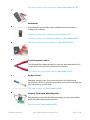
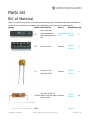
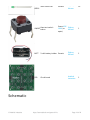
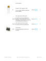
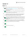
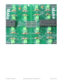
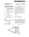
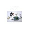
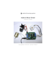
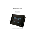
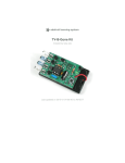
Game of Life
Created by lady ada
Last updated on 2014-04-07 11:22:25 AM EDT
Guide Contents
Guide Contents
2
Overview
4
Blinky fun cellular automata
4
Introduction
4
Make it!
5
Ready?
5
Preparation
6
Prep
6
Tools
6
Parts list
9
Bill of Material
9
Schematic
10
Optional parts
11
Solder it!
13
Make it
13
Connecting
18
Modularity
18
Older and Newer versions
18
Orientation
18
Method 1: Solder it
18
Method 2: Plug & Play
24
Make a cube!
27
Use it!
39
User manual
39
Powering your kit from AA batteries or 3V DC power supply
39
Powering your kit from 9V batteries or a 9-12V DC power supply
39
Turning on/off
39
Resetting
39
Download
40
Schematic and Layout
© Adafruit Industries
40
https://learn.adafruit.com/game-of-life
Page 2 of 42
Firmware
40
Buy Kit
41
Forums
42
© Adafruit Industries
https://learn.adafruit.com/game-of-life
Page 3 of 42
Overview
Blinky fun cellular automata
Introduction
In 1970, John Conway came up with a 1-player game called Game of Life (http://adafru.it/dgf).
The Game of Life is a mathematical game that simulates 'colonies' that grow or die based on
how crowded or lonely they are and is known for the way it creates a beautiful organic display
out of randomness.
Here is a design for a simple electronic project that plays Conway's Game of Life. Make one kit
and keep it on your desk, or attach multiple kit modules together to create a large display.
Originally created by Dropout Design, this revision adds a few extra features. You can build the
boards from the schematic and open source firmware, or buy full kits from the
Adafruit (http://adafru.it/c1Y) or Make Magazine online shops. The kit is very easy to make and
an excellent first electronics project. It is perfect for workshops since at the end everyone can
connect their completed module (http://adafru.it/c1Z) together.
Features:
Each kit displays a 4x4 grid (16 LEDs)
Connect as many kits as youd like, in any configuration, to create a larger game board.
Runs off of 2 AA batteries, but can be easily modified to run off of USB or wall-wart
power.
On/Off button to save power, also for resetting the display.
Automatically resets if the colony has died or stagnated (regeneration).
Backwards compatible with older versions.
© Adafruit Industries
https://learn.adafruit.com/game-of-life
Page 4 of 42
Make it!
Ready?
This is a very easy kit to make, just go through each of these steps to build the kit:
1.
2.
3.
4.
Tools and preparation (http://adafru.it/c20)
Check the parts list (http://adafru.it/c21)
Assemble the kit (http://adafru.it/c22)
Connect modules together (http://adafru.it/c1Z)
© Adafruit Industries
https://learn.adafruit.com/game-of-life
Page 5 of 42
Preparation
Prep
Learn how to solder with tons of tutorials! (http://adafru.it/aTk)
Don't forget to learn how to use your multimeter too! (http://adafru.it/aOy)
Tools
There are a few tools that are required for assembly. None of these tools are included. If you
don't have them, now would be a good time to borrow or purchase them. They are very very
handy whenever assembling/fixing/modifying electronic devices! I provide links to buy them,
but of course, you should get them wherever is most convenient/inexpensive. Many of these
parts are available in a place like Radio Shack or other (higher quality) DIY electronics stores.
So ldering iro n
Any entry level 'all-in-one' soldering iron that you might find at your
local hardware store should work. As with most things in life, you get
what you pay for.
Upgrading to a higher end soldering iron setup, like the Hakko FX-888
that we stock in our store (http://adafru.it/180), will make soldering
fun and easy.
Do not use a "ColdHeat" soldering iron! They are not suitable for
delicate electronics work and can damage the kit (see
here (http://adafru.it/aOo)).
Click here to buy our entry level adjustable 30W 110V soldering
iron (http://adafru.it/180).
Click here to upgrade to a Genuine Hakko FX-888 adjustable
temperature soldering iron. (http://adafru.it/303)
So lder
You will want rosin core, 60/40 solder. Good solder is a good thing.
Bad solder leads to bridging and cold solder joints which can be
tough to find.
Click here to buy a spool of leaded solder (recommended for
beginners) (http://adafru.it/145).
© Adafruit Industries
https://learn.adafruit.com/game-of-life
Page 6 of 42
Click here to buy a spool of lead-free solder (http://adafru.it/734).
Multimeter
You will need a good quality basic multimeter that can measure
voltage and continuity.
Click here to buy a basic multimeter. (http://adafru.it/71)
Click here to buy a top of the line multimeter. (http://adafru.it/308)
Click here to buy a pocket multimeter. (http://adafru.it/850)
Flush Diago nal Cutters
You will need flush diagonal cutters to trim the wires and leads off of
components once you have soldered them in place.
Click here to buy our favorite cutters (http://adafru.it/152).
So lder Sucker
Strangely enough, that's the technical term for this desoldering
vacuum tool. Useful in cleaning up mistakes, every electrical engineer
has one of these on their desk.
Click here to buy a one (http://adafru.it/148).
Helping Third Hand With Magnifier
Not absolutely necessary but will make things go much much faster,
and it will make soldering much easier.
Pick one up here (http://adafru.it/291).
© Adafruit Industries
https://learn.adafruit.com/game-of-life
Page 7 of 42
© Adafruit Industries
https://learn.adafruit.com/game-of-life
Page 8 of 42
Parts list
Bill of Material
Check to make sure your kit comes with the following parts. Sometimes we make mistakes so
double check everything and email [email protected] if you need replacements!
Image
Name Descriptio n
Part #
Distributo r Qty
© Adafruit Industries
IC1
Microcontroller
(preprogrammed
when purchased in a
kit)
ATmega48v- Digikey
10PU
Mouser
1
IC1'
28-pin socket
Generic
DigiKey
Mouser
1
C3
Ceramic 0.1uF
capacitor (104)
Generic
Digikey
Mouser
1
100 ohm 1/4W 5%
R1-R16 resistor (brown, black, Generic
brown, gold)
Digikey
Mouser
16
LED1-
Digikey
https://learn.adafruit.com/game-of-life
Page 9 of 42
LED15mm Green LED
LED16
Generic
Digikey
Mouser
6mm tact switch
ON/OFF
button
Omron B3FDigikey
1000 (or
Mouser
equiv)
1
16
BATT
2 x AA battery holder Generic
Digikey
Mouser
1
PCB
Circuit board
Adafruit
Industries
1
Schematic
© Adafruit Industries
https://learn.adafruit.com/game-of-life
Page 10 of 42
Click on the schematic for the higher-res image.
Optional parts
If you're planning to make a really large array, or you want to make this kit work with the older
Game-of-Life kits that had 9V battery inputs then here are extra parts you may need.
Image
Name Descriptio n
Part # Distributo r Qty
5V regulator
IC2
part #7805 TO-220 package
Generic Digikey
7805 Mouser
1
Digikey
Mouser
1
For older-version compatibility
100uF/6V capacitor
C1
© Adafruit Industries
If you're using a 7805, this will help
https://learn.adafruit.com/game-of-life
Generic
Page 11 of 42
power stability.
Ceramic 0.1uF capacitor (104)
C2
If you're using a 7805, this will help
power stability.
Digikey
Mouser
1
Generic Digikey
1
Generic Digikey
1
Digikey
Mouser
1
Generic
4-pin right angle male header.
For easily connecting multiple kits
N,W,S,E together. The purchase links are for
'breakaway' 36-pin header, so just buy
one and break off 4-pin pieces.
4-pin right angle female header.
N,W,S,E
For easily connecting multiple kits.
6-pin header
ICSP
© Adafruit Industries
For reprogramming chip with new
firmware.
https://learn.adafruit.com/game-of-life
Generic
Page 12 of 42
Solder it!
Make it
Open up the bag of parts and check that you have all the components.
The Bill of Materials (parts list) (http://adafru.it/c21) page has a detailed list of
everything you should have.
Take the PCB and place it in a vise or other holder so that you can easily place
and solder parts.
Heat up your soldering iron to 700degF and wet the sponge. Clean the tip if
necessary. Make sure you have all your tools!
The first step is to solder in the resistors. The resistor is the tan-with-stripes
things, they're probably on tape as that's how they come from the factory.
Remove the tape and bend the resistors into staples as shown.
The resistors are named R1 thru R16. Placing them on the PCB is easy, just look
for the image on the PCB that matches the shape of the resistor. Resistors are
no n-po larized that means you can stick them in 'either way' and they'll work
just fine.
Lets start with one resistor, place a resistor into the location labeled R1 and
make sure it sits flat against the PCB, then bend the wires out so that you can
turn over the circuit board without the resistor falling out
Do the same for the other wire.
© Adafruit Industries
https://learn.adafruit.com/game-of-life
Page 13 of 42
Put down the iron and pick up the diagonal cutters. Using the cutters, clip the
wires of the resistor right above the joint.
Repeat for all 16 resistors.
I'll show soldering all of the resistors at once, but of course you can do as many
or few at once as you'd like.
Solder and clip all of the resistors.
Next we're going to place the ceramic capacitor C3 and the wire jumper for IC2.
This kit was designed to be backwards compatible with the Dropout Design
version which had a 5V regulator and ran off of a 9V battery or wall supply. If
you're planning to use this kit with the older version, make sure you use a 7805 in
IC2. For these instructions I'm going to assume that you're not going to do that.
Simply insert the small yellow capacitor into the location named C3. Ceramic
capacitors are not polarized so you can place it 'either way.'
For IC2 we're going to jumper the chip. Use a small piece of wire such as one
cut from the resistors, bend it into a staple and thread it through the two outer
pins of IC2. (See the image left). Make sure the wire doesnt touch the middle
pad.
© Adafruit Industries
https://learn.adafruit.com/game-of-life
Page 14 of 42
Solder the jumper wire and the capacitor.
Clip the extra wire off when done.
Next we're going to solder in the socket. A chip socket is used to protect the
chip and also lets you replace it if it gets damaged somehow.
The socket has a little note in one end, make sure this matches with the little
notch in the silkscreened PCB image. In the picture shown, the notch is on the
left.
The socket has short legs so it's more likely to slip than a resistor. The easiest
way to solder the socket is to hold it against the PCB with one finger (or tape)
then solder in two points on opposite sides. Once you've got it tacked, solder in
the remaining pins.
Next are the LEDs. LEDs, unlike resistors, are polarized and must be placed
correctly or they won't light up. One leg of the LED is slightly longer than the
other. This is the positive (+) leg. If you look at the image on the PCB, you'll note
that one side has a + next to it, this tells you how to orient the LED. Make sure
the long lead goes in the hole marked +.
Place the LED flat against the circuit board and bend the leads out.
© Adafruit Industries
https://learn.adafruit.com/game-of-life
Page 15 of 42
Solder both leads of the LED.
Clip the excess leads.
Repeat for all 16 LEDs.
Place the ON/OFF/Reset button. The button is non-polar. The button will snap in
and should sit flat against the PCB.
Solder in all four pins of the button. The leads are pretty short so you shouldn't
have to clip them.
Next it's time to insert the microcontroller that does all the hard work of
calculating the game and displaying LEDs. Chips come from the factory with their
legs angled out, so press against a flat table top so that the legs are straight and
parallel.
Then insert the chip into the socket. The chip must be placed correctly, make
sure the notch at the end of the chip matches the notch in the silkscreen of the
PCB. This should be the same as the notch in the socket. In case you placed the
socket wrong, make sure the notch is at the same end that has the rectangular
grid of 6 holes marked ICSP.
© Adafruit Industries
https://learn.adafruit.com/game-of-life
Page 16 of 42
Next we'll attach the battery back. I'll show how to shorten the wires which makes
for a slightly neater appearance. It's completely not necessary though.
To shorten the wires, clip them about 2" from the pack.
You'll have to tin the ends if you clipped the wires. Heat up the wire and dab
some solder, which should wick into the wire and keep the strands from flying
out.
Next, connect up the battery pack. The red wire of the pack goes to the hole
marked with a +, the black wire goes to ground, marked with a -.
Solder in the two wires.
Time to test! Place two AA batteries (rechargables or alkalines) into the pack and
watch the Game of Life start playing. If you press the ON/OFF button you should
see a checkerboard pattern.
Time to wrap it up. Remove one side of paper from the sticky foam, place it in
the center of the battery holder. Then remove the other side.
Stick the battery pack onto the back of the PCB, near the bottom. That way the
weight of the batteries will act as a stand so that the kit can sit on your desk!
Now go read the user manual....
© Adafruit Industries
https://learn.adafruit.com/game-of-life
Page 17 of 42
Connecting
Modularity
There are tons of Game of Life kits out there but what is cool about this design is that you can
plug together multiple boards to create a mega-display! Power and communications is passed
from board to board, so the whole thing updates at once.
Older and Newer versions
If you are connecting to an older version (v1.2 or less) of the board, with a 7805, you will have
to solder in a 7805 into your kit in location IC2. Otherwise the 9V DC power will fry your GoL
module!
For these instructions, I will assume you are only connecting v1.3 or higher (Adafruit design) kits
together. If there's a button in your kit, then it's a v1.3 or higher kit.
Orientation
The modules must be connected in the correct orientation. Each module has 4 'ports' labelled
No rth, So uth, East and West. To connect a module to another, make sure that East
connects to West or No rth connects to So uth! Another way of saying it is, make use the
large Make: logo is always the same direction.
Method 1: Solder it
The easiest way to connect two modules together is to first line them up next to each other.
© Adafruit Industries
https://learn.adafruit.com/game-of-life
Page 18 of 42
Then bend a leftover small piece of wire into a staple.
© Adafruit Industries
https://learn.adafruit.com/game-of-life
Page 19 of 42
Thread it through the adjacent holes, then solder to make a connection to both boards.
© Adafruit Industries
https://learn.adafruit.com/game-of-life
Page 20 of 42
Then turn over and solder the other side too. This is a permanent connection, so make sure to
use lots of solder on both sides to get a nice strong connection.
You can also do it without wires, just put a blob of solder on both sides.
© Adafruit Industries
https://learn.adafruit.com/game-of-life
Page 21 of 42
Then drag the soldering iron between the two boards, and slowly lift it in the middle.
© Adafruit Industries
https://learn.adafruit.com/game-of-life
Page 22 of 42
With a little practice you can easily create a solder bridge.
© Adafruit Industries
https://learn.adafruit.com/game-of-life
Page 23 of 42
Don't forget to do the other side too!
Method 2: Plug & Play
Another way to connect them is to use right-angle header to allow plug-and-play of the
modules. One module has a female (receptacle) connector. The other has a male (plug)
connector. Check the parts (http://adafru.it/c21) page for links on where to buy right angle
header.
© Adafruit Industries
https://learn.adafruit.com/game-of-life
Page 24 of 42
© Adafruit Industries
https://learn.adafruit.com/game-of-life
Page 25 of 42
If you use header, make sure it looks like the image below, if everyone sticks to this convention
you'll be able to connect up to any other kit!
© Adafruit Industries
https://learn.adafruit.com/game-of-life
Page 26 of 42
Make a cube!
If you have 5 or 6 GoL boards, you can make a funky cube. First, assemble 5 or 6 boards.
© Adafruit Industries
https://learn.adafruit.com/game-of-life
Page 27 of 42
Place the first board in a vise and start with the North port.
© Adafruit Industries
https://learn.adafruit.com/game-of-life
Page 28 of 42
Put plenty of solder on the first tab.
© Adafruit Industries
https://learn.adafruit.com/game-of-life
Page 29 of 42
Solder one of the excess wire bits onto it.
© Adafruit Industries
https://learn.adafruit.com/game-of-life
Page 30 of 42
Get the next board lined up. Make sure you are connecting it to the South port.
© Adafruit Industries
https://learn.adafruit.com/game-of-life
Page 31 of 42
Bend the wire down and solder it to the second board.
© Adafruit Industries
https://learn.adafruit.com/game-of-life
Page 32 of 42
Repeat for all 4 tabs.
© Adafruit Industries
https://learn.adafruit.com/game-of-life
Page 33 of 42
Test the two boards by touching the battery case to the + and - on one of the boards. The
game should play on both boards.
© Adafruit Industries
https://learn.adafruit.com/game-of-life
Page 34 of 42
Connect a third board. The trick to knowing how to orient boards is that you can always connect
No rth and East & So uth and West ports together. In this case we connect West and North
of the new board to the existing structure.
© Adafruit Industries
https://learn.adafruit.com/game-of-life
Page 35 of 42
Test the cube after each new board to make sure you've got it on right.
© Adafruit Industries
https://learn.adafruit.com/game-of-life
Page 36 of 42
When you're done you can attach the battery pack pack and stick it onto the inside.
© Adafruit Industries
https://learn.adafruit.com/game-of-life
Page 37 of 42
© Adafruit Industries
https://learn.adafruit.com/game-of-life
Page 38 of 42
Use it!
User manual
This is a very short manual because the kit is very easy to use!
Powering your kit from AA batteries or 3V
DC power supply
This version of the GoL kit requires between 3 and 5V DC to run. That means you can't run it off
of a 9V battery. You can, however, run it off of 2 batteries or a USB cable! Any kind of AA
battery, rechargable or alkaline, is just fine. If the kit gets dim, just recharge your batteries. It
should last for about 100 hours on one set of fresh batteries! If you turn the kit off when not in
used, it will last even longer, of course.
Powering your kit from 9V batteries or a
9-12V DC power supply
If you'd like to run the kit off a 9V-12V DC wall adapter or a 9V battery, you'll need to place a
standard 7805 voltage regulator in location IC2 and remove the jumper wire. If you have
multiple kits connected together, each one will need a 7805. See the parts list for where to buy
a 7805.
Turning on/off
There's a little button on each kit which you can use to turn it on or off. This will save battery
when the kit isn't in use. Simply press-and-hold the button for a few seconds. It should display a
checkerboard pattern and then go out. The kit is now off. To turn it back on simply press the
button (you don't have to hold it though) and it will start up again.
Resetting
If you want to reset the kit (because, say, it gets into a stable pattern and you'd like it to do
something else) simply press the button but don't hold it down.
© Adafruit Industries
https://learn.adafruit.com/game-of-life
Page 39 of 42
Download
Schematic and Layout
Schematic is basically the same as the Dropout Design version, except LEDs are now common
cathod and a button has been added. The board layout was redone to allow using right angle
headers and to make assembly a little easier.
Schematic and layout files are at GitHub (http://adafru.it/c23) (CC 2.5 SA-BY) Click Download
Source (http://adafru.it/c24) to grab them.
Firmware
The v1.3 firmware, based heavily on the Dropout Design code. Added:
Supports a On/Off/Reset button
Auto-reset on static-image
Slightly slower delay between steps
LEDs are common cathode
Download from GitHub (http://adafru.it/c23), released under GPL. Click Download
Source (http://adafru.it/c24) to grab them.
© Adafruit Industries
https://learn.adafruit.com/game-of-life
Page 40 of 42
Buy Kit
Buy Kit (http://adafru.it/c1Y)
© Adafruit Industries
https://learn.adafruit.com/game-of-life
Page 41 of 42
Forums
Forums (http://adafru.it/forums)
© Adafruit Industries
Last Updated: 2014-04-07 11:22:28 AM EDT
Page 42 of 42