1
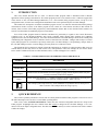
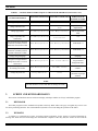
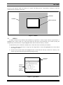
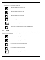
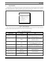
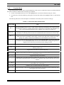
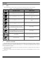
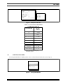
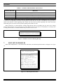
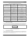
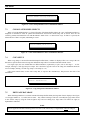
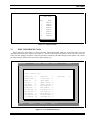
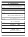
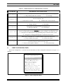
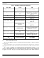
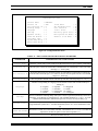
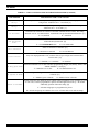
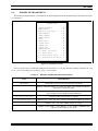
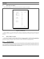
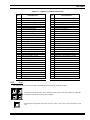
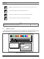
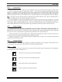
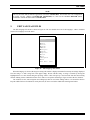
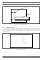
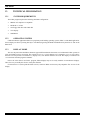
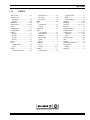
LBI-39056 Mobile Communications EDACSTM C3 MAESTRO CONSOLE SYSTEM EDITOR PROGRAM User's Manual LBI-39056 TABLE OF CONTENTS Page 1. INTRODUCTION ................................................................................................................................ 5 2. QUICK REFERENCE ......................................................................................................................... 5 3. SCREEN AND KEYBOARD BASICS ................................................................................................ 6 3.1 KEYBOARD................................................................................................................................ 6 3.2 WINDOWS .................................................................................................................................. 6 3.3 MENUS ........................................................................................................................................ 7 3.4 FORMS ........................................................................................................................................ 8 3.5 PROMPTS ................................................................................................................................... 10 4. RUNNING EDITOR ............................................................................................................................ 4.1 STARTING.................................................................................................................................. 4.2 PASSWORD ................................................................................................................................ 4.3 EXITING ..................................................................................................................................... 4.4 HELP ................................................................................................................................ ........... 10 10 10 10 10 5. MAIN MENU ....................................................................................................................................... 11 6. EDIT ENTITY DATABASE................................................................................................................ 6.1 EDITOR SCREEN ...................................................................................................................... 6.1.1 Information Lines ................................................................................................................ 6.1.2 Function Menu .................................................................................................................... 6.2 KEYS ........................................................................................................................................... 6.3 EDITING A RECORD ................................................................................................................ 6.4 SORTING RECORDS................................................................................................................. 12 12 12 13 14 14 15 7. EDIT SETUPS/PROFILES.................................................................................................................. 7.1 SELECT SETUP NUMBER........................................................................................................ 7.2 CLEAR STARTUP MODULES.................................................................................................. 7.3 CLEAR PATCH/SIMULSELECTS............................................................................................ 7.4 COPY SETUP.............................................................................................................................. 7.5 EDIT PAGE DATABASE ........................................................................................................... 7.6 EDIT USER PROFILE DATA.................................................................................................... 16 17 17 18 18 18 19 8. EDIT CONFIGURATION ................................................................................................................... 8.1 EDIT CONFIG DATABASE....................................................................................................... 8.2 DISABLE KEYBOARD KEYS .................................................................................................. 8.3 EDIT SITE DATABASE ............................................................................................................. 8.4 EDIT SCREEN COLORS ........................................................................................................... 8.4.1 Color Descriptions ............................................................................................................... 8.4.2 Keys .................................................................................................................................... 8.5 EDIT DAC VALUES................................................................................................................... 8.5.1 About Colors........................................................................................................................ 8.5.2 Palette Window.................................................................................................................... 8.5.3 Samples Window ................................................................................................................. 8.5.4 Keys .................................................................................................................................... 8.5.5 Accepting Changes .............................................................................................................. 8.6 READ SPECIAL CONFIG FILE................................................................................................ 8.7 SAVE CHANGES TO DISK ....................................................................................................... 21 22 25 26 26 26 27 28 29 29 29 29 30 30 30 Copyright February 1994, Ericsson GE Mobile Communications, Inc. 2 LBI-39056 TABLE OF CONTENTS (Continued) Page 9. EDIT LANGUAGE FILES................................................................................................................... 31 10. VIEW AUX I/O................................................................................................................................... 32 11. CHANGE PASSWORD...................................................................................................................... 33 12. COMPATIBILITY ............................................................................................................................. 33 13. TECHNICAL INFORMATION......................................................................................................... 13.1 SYSTEM REQUIREMENTS .................................................................................................... 13.2 OPERATING SYSTEM............................................................................................................. 13.3 DISPLAY MODE....................................................................................................................... 34 34 34 34 14. INDEX ................................................................................................................................................. 35 TABLES TABLE 1 − CHARACTER STYLES AND SYMBOLS USED IN THIS MANUAL....................... TABLE 2 − CONFIGURABLE ITEMS UNIQUE TO THE EDITOR PROGRAM....................... TABLE 3 − MAIN MENU SELECTIONS........................................................................................ TABLE 4 − FUNCTION MENU SELECTIONS.............................................................................. TABLE 5 − ENTITY EDITOR AND ENTITY RECORD SELECTIONS...................................... TABLE 6 − ENTITY RECORD FORMS VALIDATION CHECKS............................................... TABLE 7 − SORTING METHOD MENU SELECTIONS .............................................................. TABLE 8 − EDIT SETUPS/PROFILES MENU SELECTIONS...................................................... TABLE 9 − USER PROFILE DATA PARAMETERS..................................................................... TABLE 10 − EDIT MENU CONFIGURATION SELECTIONS..................................................... TABLE 11 − EDIT CONFIGURATION DATABASE PARAMETERS.......................................... TABLE 12 − DISABLE KEYBOARD KEYS SELECTIONS.......................................................... TABLE 13 − SCREEN COLOR DESCRIPTIONS .......................................................................... TABLE 14 − VIEW AUX I/O FIELDS ............................................................................................. 5 6 11 13 14 15 16 17 20 22 23 25 27 33 NOTE Information in this document is subject to change without notice. CREDITS IBM is a registered trademark of International Business Machines Corporation. PC-AT is a trademark of International Business Machines Corporation. MS-DOS is a registered trademark of Microsoft Corporation. 3 LBI-39056 (This page intentionally left blank) 4 LBI-39056 1. INTRODUCTION This user's manual describes the use of the C3 Maestro Editor program which is distributed with C3 Maestro application software package 344A3922Gxx. The Editor program provides a user interface to the C3 Maestro support files in the absence of the CEC/IMC Manager (MOM PC). It is a non-essential utility program because, except for a few configuration items, all of the same configuration and database tasks can be performed by the CEC/IMC Manager. This manual was developed in accordance with Editor program Version 3.10 which is included with software package 344A3922G10. Earlier versions of the Editor program do not contain all of the features described in this manual. In contrast, future versions of the Editor program may contain additional features that are not described in this manual. See Section 12 in this manual for additional program version details. Users of the Editor program should be familiar with EDACS, particularly in regards to the Console Electronics Controller (CEC) or the Integrated Multisite and Console Controller (IMC) Digital Audio Switches and supporting equipment such as the CEC/IMC Manager. Users must understand that the CEC/IMC Manager should be the central point of databasing and configuration for all C3 Maestro consoles connected to the CEC/IMC. Changes made locally at a console by the Editor program can override those previously made by the CEC/IMC Manager. Correspondingly, changes made at the CEC/IMC Manager can also override changes previously made at a C3 Maestro console. This document shall not attempt to explain in detail the implications or workings of system parameters that can be set with the Editor, but how they can be set, and in most cases, valid parameter values. For example, the user will be shown how to enable Confirmed Call, but not what Confirmed Call is, or what will happen if it is enabled. TABLE 1 − CHARACTER STYLES AND SYMBOLS USED IN THIS MANUAL 2. EXAMPLE DESCRIPTION Display Courier type is used to simulate information that appears on the computer screen.. CONFIG.DAT Bold CAPITAL letters are used for the names of files used with Editor. This style is also used to indicate MS-DOS commands, COPY, for example. User Input Words in italics are data that the user must supply by typing from the keyboard. Italics may also be used occasionally in the text for emphasis. <Enter> Words inside angle brackets (< >) identify certain keys on the keyboard that the user must press to perform a specific function. Examples include <Enter> and <F1>. Page Up This example symbol represents a key on the standard PC keyboard that the user must press to make a selection. This example shows the <Page Up> key. QUICK REFERENCE This section is primarily intended to aid users who are already familiar with the Editor program. Users who are new to the Editor should proceed to Section 3 to learn Editor operating details. Table 2 lists, in the "ACTION OR CHANGE" column, the more common configurable items that are unique to the Editor program. It highlights the more common items that cannot be changed at the CEC/IMC Manager. It is a noninclusive list for all unique configurable items. The table also shows the menu(s) to select to advance to the field or window to make the changes. 5 LBI-39056 TABLE 2 − CONFIGURABLE ITEMS UNIQUE TO THE EDITOR PROGRAM (Non-Inclusive List) MAIN MENU SELECTION NEXT MENU SELECTION ACTION OR CHANGE FORM ITEM OR ACTION TO TAKE Purge entity database Edit Entity Database Erase DB n/a Change sidetone levels Edit Setups/Profiles Edit User Profile Data Opr Sidetone (or) Sup Sidetone Change page names Edit Setups/Profiles Edit Page Database Edit any page name field Purge old patches and simulselects Edit Setups/Profiles Clear Patch/ Simulselects n/a Set serial port for 19.2k baud connection (normally used for hardwired connection to CIM) Edit Configuration Edit Config Database 19.2K Baud = Y Set serial port for 9600 baud connection (normally used for modem connection to CIM) Edit Configuration Edit Config Database 19.2K Baud = N Change foreign language Edit Configuration Edit Config Database Language Edit Configuration Edit Screen Colors Select field and change foreground and background colors. Change RGB components (hue) of an existing screen color Edit Configuration Edit DAC Values Select color and move "sliders". Change the password Change Password (none) Enter current and new passwords in prompt windows. Assign new foreground and background colors to a screen field or area NOTE All data should be saved to disk after the changes are made. 3. SCREEN AND KEYBOARD BASICS This section will familiarize the user with screen display techniques and the use of keys in the Editor program. 3.1 KEYBOARD The Editor program uses the standard PC keyboard exclusively. Both "white" and "gray" navigation keys can be used for cursor-positioning functions. The custom Maestro keyboard is never used during the operation of the Editor. 3.2 WINDOWS A window is a rectangular area on the screen that appears temporarily for the purpose of viewing information or entering data. When the user acknowledges the information or completes a data entry task, the window is erased and the 6 LBI-39056 previous screen contents "under" the window are restored. The Editor uses the "drop-shadow" technique to make the windows appear to float above the screen. WINDOW SCREEN DROP-SHADOW Figure 1 − Window 3.3 MENUS A window in which various functions and commands are organized is a "menu". Figure 2 shows a typical menu. A highlighted bar is used to mark one of the menu items. This bar moves up and down the list of items by using the navigation keys. Most items have a single highlighted letter used for instant or "hot-key" selection. A menu item may select a function or another menu. A menu item can be selected by two methods: • • Use the up and down arrow keys or <Page Up> and <Page Down> to move the highlighted bar over the desired item and press <Enter>. Press the letter key that matches the highlighted letter in each item title. This key is known as a "hot-key". The <Enter> key does not need to be pressed after pressing a hot-key. EDITOR MAIN MENU Highlighted Letter for "Hot Key" Selection (Instant Execution) Highlighted Selection Edit Entity Database Edit Setups/Profiles Edit Configuration Edit Language Files View Aux I/O Change Password About Editor Exit to DOS (Esc) Figure 2 − Typical Menu 7 LBI-39056 The following keys are used to navigate around a menu: Moves the highlighted bar to the previous item. Moves the highlighted bar to the next item. Page Up Moves the highlighted bar to the first item. Page Down Moves the highlighted bar to the last item. Enter Esc 3.4 Selects the item under the highlighted bar. Returns to the previous menu, or exits to MS-DOS from the Main Menu. FORMS A window that requires or accepts user input is a "form". A form is made up of "fields" in which the user enters data. A field may require as little as a single character, for example, "Y" for yes, or several characters. The following keys are used to navigate around a form or field: Moves the cursor to the beginning of the previous field. Moves the cursor to the beginning of the next field. Home End Tab 8 Moves the cursor to the beginning of the current field. Moves the cursor to the end of the current field. Moves the cursor to the beginning of the next field. LBI-39056 Enter If pressed without entering data, the current field data remains unchanged and the cursor moves to the beginning of the next field. Exits the form. Esc The following keys are used for form editing: Enter Backspace Completes user input on the current field and moves the cursor to the beginning of the next field. Deletes the character to the left of the cursor but does not affect the character under the cursor. Deletes the character under the cursor and shifts the text to the right of the cursor to the left. The cursor does not move. Del When the cursor is at the end of a field and the user attempts to enter more characters than the width of the field, a beep will sound and the cursor will not move any farther to the right. A form can be completed in three ways: • • • editing the last field on the form moving across all fields with arrow keys or by pressing <Enter> repeatedly pressing <Esc> anywhere on the form When a form is completed, the following message is displayed (The data is not accepted at this point): Press ENTER to accept, ESC to abort changes, any other key to Re-edit At this point the data can be accepted (existing data is overwritten), exited without saving changes, or edited again. These keys are defined as follows: Enter Esc (Any other) The data on the form is accepted and stored in memory. Previous data is overwritten. The form is exited. All new data entered on the form is ignored and the previous data remains current. The cursor moves to the first field for further editing. No new data has been accepted but the new data remains in temporary storage. NOTE The data in some fields will be automatically right-justified when <Enter> is pressed after entering numeric data that is less than the width of the field. This will also occur when numeric fields are passed over using the arrow keys. This right-justification is normal; the field data is unaffected. 9 LBI-39056 3.5 PROMPTS A prompt is a small one-line form which prompts the user to enter a number or a yes/no response. For yes/no prompts, a yes or no default answer is displayed at the cursor position. If <Enter> is pressed, the default answer is accepted as the answer. For example, if the default answer is "Y" (yes), and the user wishes to answer yes to the prompt question, only <Enter> must be pressed. A prompt with a "No" default answer is shown in Figure 3. Confirm ERASE startup modules? N Figure 3 − Typical Prompt 4. RUNNING EDITOR This section will instruct the user in the basics of starting and ending the Editor program. It will also show how to get on-line help during the operation of the program. 4.1 STARTING Start Editor from the MS-DOS prompt by typing EDITOR followed by <Enter>. The current directory must be C:\CONSOLE. The Editor's copyright screen will be displayed for five seconds or until any key is pressed. This copyright screen includes Ericsson GE copyright information and the program's version number. If password control is not enabled the Editor Main Menu is displayed after the copyright screen. 4.2 PASSWORD Editor is protected from unauthorized use by means of a password. Password control can be enabled or disabled. If enabled, a small window will be displayed after the copyright screen. This window will prompt the user for a password. The password will not be echoed to the screen; however, the cursor will move to indicate user input. The password is not casesensitive and the backspace key may be used for editing. The password can be changed or disabled, but only if the current password is known. There is no password when Editor is installed on a new system. It is up to the user to set a password, if desired. 4.3 EXITING To exit Editor from any menu or form, press <Esc> repeatedly until the screen is cleared and the MS-DOS prompt is visible again. If data is not saved before exiting with multiple <Esc> presses, the data in memory will be lost and the file data will remain unchanged. 4.4 F1 10 HELP Help is available by pressing <F1>. Help is context sensitive. In other words, help is displayed for the selected field when <F1> is pressed. Help appears as a single line of text at the bottom of the screen. It temporarily overwrites any text on the bottom row. Help text is erased and the previous text re-appears upon the next key stroke (any key). The help text must be erased to continue. LBI-39056 5. MAIN MENU The Main Menu is the starting point from which all Editor operations begin. This menu appears after the copyright screen and password window (if enabled) are displayed. After an editing session has been completed, the user will always return to the Main Menu before exiting to MS-DOS. The Main Menu is shown in Figure 4. EDITOR MAIN MENU Edit Entity Database Edit Setups/Profiles Edit Configuration Edit Language Files View Aux I/O Change Password About Editor Exit to DOS (Esc) Figure 4 − Editor Main Menu Table 3 briefly describes the actions that follow a menu selection and how the menu selection is used. Most of the menu items have an entire section devoted to their use. Hot-key letters are shown in bold type. TABLE 3 − MAIN MENU SELECTIONS MENU ITEM ACTION USE Edit Entity Database Accesses the entity database edit screen Editing of entity database file ENTITY.DAT. This includes the entity name, privilege, and home site. (Section 6) Edit Setups/Profiles Displays the Edit Setups/Profiles Menu Editing of user profiles, setup titles, and page names. Clearing startup modules, patches and simulselects. (Section 7) Edit Configuration Displays the Edit Configuration Menu Editing console configuration, including hardware parameters, site names, and screen colors in CONFIG.DAT. (Section 8) Edit Language Files Displays the Edit Language File Menu Editing English or foreign language text strings displayed by the console application. (Sec. 9) View Aux I/O Displays the Auxiliary I/O screen View the contents of AUXIO.DAT. (Sec.10) Change Password Prompts user for current and new passwords Change the current password to a new password. (Section 11) About Editor Displays a window describing the Editor program General information. Exit to DOS Terminates program, returns user to MS-DOS prompt Returns to MS-DOS prompt. 11 LBI-39056 When one of the "Edit" or "View" selections is made, a file related to that selection will be opened. If the file is missing or cannot be opened for some reason, the window shown in Figure 5 will be displayed. "XXXXXXXX" can be "ENTITY", "CONFIG", "PHONE", "AUXIO" or a language name. If the file is missing, it can be copied from the Maestro installation disk or from another console. XXXXXXXX.DAT open error. Press any key to continue. Figure 5 − File Open Error Message 6. 6.1 EDIT ENTITY DATABASE EDITOR SCREEN The entity database editing screen is composed of four main sections, the top and bottom Information Lines, the Function Menu, and the main editing area. The screen layout is shown in Figure 6. 6.1.1 Information Lines The top and bottom lines of the screen display current file and edit memory parameters. The top line shows the name of the file being edited, the file size, and the date and time the file was last saved. The filename will always be ENTITY.DAT. The file size will vary depending on the number of entities in the file. A reminder about the help key is located at the right end of the line. The bottom line shows the current number of each type of entity. ENTITY.DAT TOP INFORMATION LINE FUNCTION MENU FILE NAME FILE SIZE 32128 bytes LAST SAVED 02/28/94 12:34:56 Edit Delete Sort Write File Erase DB Privilege All Pvlg Find Name Find Next Find ID NUM 0 1 2 3 4 5 6 7 8 9 10 11 . . 19 __ID_ 1234 1240 1285 273 274 289 1 1 2 801 802 803 Units: 1234 TYPE U U U G G G C T T X X X HGROUP 273 273 273 0 0 0 HSITE 1 1 1 1 1 1 1 HIGHLIGHTED ENTITY RECORD EDIT AREA Groups: 85 Convs: 4 F1=Help Pvt All Pvt Hex Mode Quit PRVLG Y Y PVT Y Y Y Y Y Y Y Y Y Y Y Y Phones: 0 __NAME__ SMITH P BROWN P JONES P N PATROL S PATROL E PATROL FIRE 1 LINE 1 LINE 2 CONS 01 CONS 02 SUPR CON Consoles: 6 BOTTOM INFORMATION LINE (CURRENT NUMER OF EACH TYPE) Figure 6 − Entity Editor Screen 12 LBI-39056 6.1.2 Function Menu The Function Menu is located on the second and third lines of the screen. It contains the fourteen (14) editing functions that can be executed. A function can be selected by two methods: • • Use the left and right arrow keys to move the highlighted bar over the desired function and press <Enter>. Use the hot-key selection method by pressing the letter key that matches the highlighted letter in each function title. The following table shows a brief description of each function. The hot-key letter is shown is bold type. TABLE 4 − FUNCTION MENU SELECTIONS MENU ITEM USE Edit Edits the highlighted entity record. A small window containing an information form is displayed when the function is selected. A secondary form window is displayed for conventional-only information. If the record is blank the data from the form is added as a new entity. (See Section 6.3) Delete Deletes the highlighted entity record from memory. Deleting is immediate − there is no prompt for confirmation. Accidentally deleted records are not permanently deleted until the file is saved to disk. Sort Sorts the entity records according to the sorting method selected when this function is selected. The sorting can be done by ID number, Name (alias), or Home Group. Records are sorted by type (unit, group, conv., phone, console) first, and then by the selected method. (See Section 6.4) Write File Writes (saves) the file image in memory to a disk file named ENTITY.DAT. The previous entity data is written to a file named ENTITY.OLD. If the file has not been sorted, a warning message will be displayed. It is not necessary to sort the file before writing it to disk. Erase DB Erases all records in the file image. A confirmation window is displayed before the data is erased. Pvt Toggles the private status for the highlighted entity. “Y” indicates private status is set and a blank indicates private is off. All Pvt Toggles the private status for all units and groups. Privilege Toggles the privilege for the highlighted entity. "Y" indicates that the privilege is set; blank indicates the privilege is off. All Pvlg Toggles the privilege for all entities. Find Name Finds the first record whose name (alias) matches the search string. The search string is entered in a small window when this function is selected. Up to 8 characters can be entered. The search is not case sensitive. Find Next Finds the next match(s) of the search string. This function can be repeated to find all entities whose name matches the search string. Find ID Finds the first record that matches the search number. Hex Mode Toggles the display of IDs between decimal and hexadecimal. The display mode is hexadecimal when a check appears next to the word "Hex". Quit Returns the user to the Main Menu. 13 LBI-39056 6.2 KEYS Table 5 identifies the keys and key actions used to navigate around the entity editor or entity record form: TABLE 5 − ENTITY EDITOR AND ENTITY RECORD SELECTIONS KEY MAIN EDIT ACTION FORM ACTION Moves the highlight bar to the previous record. Moves the cursor to the beginning of the previous field. Moves the highlight bar to the next record. Moves the cursor to the beginning of the next field. Home Moves the highlight bar to the first record. Moves the cursor to the beginning of the current field. End Moves the highlight bar to the last record. Moves the cursor to the end of the current field. Page Up Does nothing. Page Down Moves the highlight bar to the last record on the current page or to the last record on the next page if already at the bottom of the current page. Does Nothing. Enter Executes the current highlighted function on the Function Menu. Completes the entry on the current field. Exits the main edit. Exits the form. Esc 6.3 Moves the highlight bar to the first record on the current page or to the first record on the previous page if already at the top of the current page. EDITING A RECORD When "Edit" has been selected from the Function Menu, the left-hand record edit form shown in Figure 7 is displayed. If the selected record exists, the current data is displayed in the form; otherwise, the data displayed is undefined. The user should enter the required data to complete the form. If the type is "C" (conventional), the right-hand form will be displayed after the left-hand form is complete. Table 6 shows the validation checks made on the entered data. Since the data is not rigidly checked, the user should use care when entering the data. After the form is complete, the data will be displayed in the main edit area and the highlighted bar will move down to the next record. 14 LBI-39056 ID : TYPE : HOME GROUP: HOME SITE : PRIVILEGE : PRIVATE : NAME : 273 G 0 1 Y N N PATROL CHANNEL: 32 MAX RX : 1 MAX TX : 1 Figure 7 − Entity Record Forms TABLE 6 − ENTITY RECORD FORMS VALIDATION CHECKS PARAMETER RANGE CHECK ID 1 - 16382 Type None Home Group * 0 - 2047 Home Site 0 - 32 Privilege "Y" or "N" Private "Y" or "N" Name Max. 8 characters Channel 1 - 99 Max RX/TX 1-8 * Zero is a valid home group for a group, conventional, or phone. 6.4 SORTING RECORDS The Sorting Method Menu is displayed when "Sort" is selected from the Function menu. See Figure 8. SORTING METHOD ID Number Name Home Group Figure 8 − Sorting Method Menu 15 LBI-39056 TABLE 7 − SORTING METHOD MENU SELECTIONS SORTING METHOD RESULTS ID Number Records are sorted by type and then numerically by ID number. Name Records are sorted by type and then alphabetically by name. Home Group Records are sorted by type, numerically by home group, and then numerically by ID. During the sorting process, blank records are eliminated and the file size of the potential new file is recalculated. Consoles are sorted separately from units even though they reside in the same ID space. The alphabetic sorting is done by ASCII value; therefore, a name beginning with a number will come before any name beginning with a letter and names with leading spaces will come before any name beginning with a number or letter. When "Write File" is selected from the Function Menu directly after record editing, the user will see the warning message shown in Figure 9. It is not necessary to sort the database before saving. However, if the database is sorted previous to saving, blank records are eliminated and the entity records are easier to view. WARNING: Database is not sorted! Figure 9 − Database Not Sorted Warning Message 7. EDIT SETUPS/PROFILES When "Edit Setups/Profiles" is selected from the Main Menu, the Edit Setups/Profiles Menu is displayed. See Figure 10. EDIT SETUPS/PROFILES About This Menu Select Setup Number Clear Startup Modules Clear Patch/Simulselects Copy Setup Edit Page Database Edit User Profile Data Save Changes to Disk Restore Initial Database Quit Changes and Return Return to Main Menu (Esc) Figure 10 − Edit Setups/Profiles Menu 16 LBI-39056 TABLE 8 − EDIT SETUPS/PROFILES MENU SELECTIONS MENU ITEM ACTION USE About This Menu Displays a window containing brief information about the parameters that can be edited. General information Select Setup Number Prompts user for setup number. (Section 7.1) Setting the current setup number for all setup editing. Clear Startup Modules Prompts user to confirm clearing. (Section 7.2) Erasing all startup modules from the current setup. Clear Patch/Simulselects Prompts user to confirm clearing. (Section 7.3) Erasing all patches and simulselects from the current setup. Copy Setup Prompts user for source and destination setups. (Section 7.4) Copying the contents of one setup to another setup, or to all other setups. Edit Page Database Displays Page Data form for current setup. (Section 7.5) Editing the test of the page names displayed in the page window. Edit User Profile Data Displays User Profile Data screen for current setup. (Section 7.6) Editing of numeric and yes/no parameters in the user profile of the current setup. Save Changes to Disk Prompts user to save changes to disk. Saving the setup changes to the SETUPS.DAT file. Restore Initial Database Restores setup database to the save values before editing began. Restoring the memory image of the database to its values previous to editing. Quit Changes and Return − and − Return to Main Menu (Esc) Returns user to Main Menu. Select other main editing functions or return to MS-DOS. 7.1 SELECT SETUP NUMBER When "Select Setup Number" is selected from the Edit Setups/Profiles Menu, the Setup Number Window is displayed. This number must be set to the number of the setup that is to be edited and saved. It must be set before editing begins. It remains the current setup number until it is changed or the Edit Setups/Profiles Menu is exited. The default number is 1. Setup number: Figure 11 − Select Setup Number Window 7.2 CLEAR STARTUP MODULES When "Clear Startup Modules" is selected from the Edit Setups/Profiles Menu, the erase confirmation window is displayed. If confirmed as YES, all startup modules stored in the current setup will be erased. Startup modules are those that are programmed when the Maestro application starts up and establishes a link with the CEC/IMC. If <Enter> is pressed, the default answer of No is accepted and nothing is erased. 17 LBI-39056 Confirm ERASE startup modules? N Figure 12 − Clear Startup Modules Erase Confirmation Window 7.3 CLEAR PATCH/SIMULSELECTS When "Clear Patch/Simulselects" is selected from the Edit Setups/Profiles Menu, the erase confirmation window is displayed. If confirmed as YES, all patches and simulselects stored in the current setup will be erased. These are the "memory" patches and simulselects seen with the Maestro <Patch View> or <Simul View> keys. If <Enter> is pressed, the default answer of NO is accepted, and nothing is erased. Confirm ERASE patch/ss? N Figure 13 − Clear Patch/Simulselects Erase Confirmation Window 7.4 COPY SETUP When "Copy Setup" is selected from the Edit Setups/Profiles Menu, a window is displayed. The source setup is the one that will be copied to the destination setup; the destination setup will be overwritten with data from the source. For single copies, the user should enter two different numbers, separated by a space, each in the range 1 - 10. For example, entering 2 8 will copy setup 2 to setup 8. If it is desired to copy the source to all setups, the destination should be 99. For example, entering 1 99 will copy setup 1 to all setups (2 - 10). Only source numeric data, not the source setup title, is copied to the destination(s). This preserves the titles of all destinations. Source Destination: Figure 14 − Copy Setup Source/Destination Window 7.5 EDIT PAGE DATABASE When "Edit Page Database" is selected from the Edit Setups/Profiles Menu, the Page Data form is displayed. See Figure 15. The page numbers (1 - 8) on the form are static − they cannot be changed. The user can modify the page names stored in the current setup by using the form navigation keys and text editing keys. Page names are limited to eight (8) alphanumeric characters. NOTE Maestro application module numbering format of a letter (A-H) followed by a 2-digit number cannot be changed. 18 LBI-39056 PAGE DATA NUM 1 2 3 4 5 6 7 8 __NAME__ PAGE-A PAGE-B PHONES PAGE-D PAGE-E PAGE-F PAGE-G PAGE-H Figure 15 − Page Data Form 7.6 EDIT USER PROFILE DATA When "Edit User Profile Data" is selected from the Edit Setups/Profiles Menu, the User Profile Data form and top/bottom information line is displayed. See Figure 16. All of the user profile data parameters shown in Table 9 can be set at the CEC/IMC Manager except the setup Title parameter. Subsequent CEC/IMC Manager profile updates will override any Editor changes. Default values are shown in square brackets ([ ]). SETUPS.DAT 17920 bytes 02/28/94 16:50:22 F1=Help USER PROFILE DATA TITLE : Operator Setup 1 SUPERVISOR : N DEFAULT SPKR : 2 24 HOUR TIME : Y EMERG VOL : 16 UNSEL LABELS : Y MUTE VOL : 0 NUMERIC LABELS : N MUTE DELAY : 30 NUMERIC VOLUME : N LABEL DELAY : 0 AUTO ALARM OFF : Y BLANK DELAY : 0 BEEP W/ERROR DEFAULT VOL : 16 RST BEFORE CLR : N MAX CNFM DEL : 0 DISP FAILSOFT TONE OFFSET DEBUG MESSAGES : N : Y OPR SIDETONE : 150 RT UNPRIV EMER : N SUP SIDETONE : 150 CONFIRMED CALL : N SETUP: 1 Modules: 6 Patches: 0 : N : N MIN ALRM VOL : 16 : 5 FORCE TONES Simuls:0 Figure 16 − User Profile Data Screen 19 LBI-39056 TABLE 9 − USER PROFILE DATA PARAMETERS PARAMETER DESCRIPTION AND VALID VALUES Title Setup Title. This is the current setup's title displayed on the Maestro "Change Setup" notecard. It can contain up to 31 printable ASCII characters. [Operator Setup x] Default Vol Default unselect volume. This is the volume at which all newly programmed entities are set to. Valid range is 0 - 32. [16] Default Spkr Default unselect speaker. This is the unselect speaker to which all newly added entities are set. Valid numbers are 2 for a single PA Board system, or 2 - 4 for a dual PA Board system. [2]. Emer Vol Emergency volume. Valid range is 0 - 32. [16] Mute Vol Mute volume. This is the volume to which a module will be set when muted. Valid range is 0 - 32. [0] Mute Delay All-Mute Delay. This is the delay, in seconds, that all-mute will remain active until it is automatically canceled. Valid range is 0 - 60. [30] Label Delay Call and Caller label delay. This is the delay (or hang-time), in seconds, that these fields will remain active after a call has actually dropped. Valid range is 0 - 10. [0] Blank Delay Screen blanking delay. This is the delay, in minutes, that the screen will remain on, without key or call activity, before going blank. 0 disables the feature. Valid range is 0 - 30. [0] Min Alrm Vol Minimum alarm volume. See CEC/IMC documentation for details. Valid range is 0 - 32. [16] Max Cnfm Del Maximum confirmed call delay in seconds. Reserved for future use. [0] Tone Offset Confirmation and system tone offset in dBm. See CEC/IMC documentation for details. Valid range is 0 - 20, which translates to 0 to -20 dBm. [5] Opr Sidetone Operator headset sidetone level setting for digital pot on the Audio Matrix Board. Applies to AMB Rev. A or later. Valid range is 0 - 255. [150] Sup Sidetone Supervisor headset sidetone level setting for digital pot on the Audio Matrix Board. Applies to AMB Rev. A or later. Valid range is 0 - 255. [150] Supervisor Supervisor console and supervisor privileges [N] Y = Supervisor 24 Hour Time 12/24 time display mode. [Y] Y = 24 hour (military) time Unsel Labels N = Only selected callers LID, GID, etc. numbers used instead of aliases in module displays. [N] Y = Display IDs Numeric Volume N = 12 hour time Caller aliases (labels) displayed on unselected calls. [Y] Y = All callers displayed Numeric Labels N = Normal operator N = Display aliases Numeric module volume level (0 - 32) used instead of volume bar. [N] Y = Numeric value N = Volume bar Audible alarms automatically reset by emergency clear. [Y] Auto Alarm Off Y = Alarm reset when emergency is cleared. N = Alarm must be manually reset, even if emergency is clear. (Continued) 20 LBI-39056 TABLE 9 - USER PROFILE DATA PARAMETERS (Continued) PARAMETER Beep w/Error DESCRIPTION AND VALID VALUES Beeps (error tones) when keyboard errors occur or warning message banners are displayed. Y = Beep with keyboard error or banner Rst Before Clr Reset Emergency Before Clear. Alarm reset (acknowledge) is required before <EMER CLR> key will clear emergency. [N] Y = Alarm must be reset first Disp Failsoft N = <EMER CLR> works all the time. Failsoft/trunking status indicator is displayed. [Y] Y = Display indicator Debug Messages N = No display Development mode debug messages are displayed. [N] Y = Messages displayed Rt Unpriv Emer N = No beeps N = No messages Route unprivileged emergencies on to supervisor console. An unprivileged emergency is one that occurs on an unprivileged and unprogrammed group. Does not apply to non-supervisors. [N] Y = Emergencies on unprivileged and unprogrammed groups are declared on the console. N = Emergencies on unprogrammed groups are declared on the console. Confirmed Call Enables group confirmed call, i.e confirmed channel request from console. [N] Y = Group confirmed call requests Force Tones Beeps, error, confirmation, emergency, etc. tones are forced to the select speaker or headset even if the tone is related to an unselected entity. [N] Y = Tones to select speaker or headset 8. N = Normal call requests N = Tones follow entity EDIT CONFIGURATION When "Edit Configuration" is selected from the Main Menu, the Edit Configuration Menu shown in Figure 17, is displayed. EDIT CONFIGURATION About This Menu Edit Config Database Disable Keyboard Keys Edit Site Database Edit Screen Colors Edit DAC Values Read Special Config File Save Changes to Disk Restore Initial Database Quit Changes and Return Return to Main Menu (Esc) Figure 17 − Edit Configuration Menu 21 LBI-39056 TABLE 10 − EDIT MENU CONFIGURATION SELECTIONS MENU ITEM ACTION USE About This Menu Displays a window containing brief information about the parameters that can be edited. General information Edit Config Database Displays the Configuration Data form. Editing numeric and yes/no parameters used by the application at startup. (Section 8.1) Disable Keyboard Keys Displays the Disable Keys form Disabling certain keys on the dispatch keyboard (Section 8.2) Edit Site Database Displays the Site Data form. Editing the text of the site names. (Section 8.3) Edit Screen Colors Displays the Screen Colors form. Changing the colors assigned to various fields and areas of the Maestro screen. (Section 8.4) Edit DAC Values Displays the Edit DAC Values control panel. Read Special Config File Prompts the user for a configuration filename. Reading a special configuration file in for editing other than the default, CONFIG.DAT. (Section 8.6) Save Changes to Disk Prompts user to save changes to disk. Saving the configuration changes to a file. The default is CONFIG.DAT. (Section 8.7) Restore Initial Database Restores setup database to the values before editing began. Quit Changes and Return − and − Return to Main Menu Returns user to Main Menu. 8.1 Changing the RGB values of the individual colors used by the application. (Section 8.5) Restoring the memory image of the database to its values previous to editing. Select other main editing functions or return to MS-DOS. EDIT CONFIG DATABASE When "Edit Config Database" is selected, the Configuration Data form shown in Figure 18 is displayed. This figure shows default data. The user can modify data by using the form navigation and text editing keys. The numeric data fields have different field widths depending on the maximum value that may be entered. The yes/no fields in the right column can only contain "Y" or "N". Table 11 describes the parameters on the Configuration Data form. Parameters followed by an asterisk (*) are not settable at the CEC/IMC Manager; these items can only be changed by the Editor. Changes to parameters not marked with an asterisk (*) will override values from the CEC/IMC Manager and subsequent CEC/IMC Manager configuration messages will override any Editor changes. Default values are shown in square brackets. 22 LBI-39056 CONFIGURATION DATA Console Name Console ID Call Director ID Startup Setup Language CLB IRQ Speaker Config Tower PA Boards CTIS Hang Time System Msg Delay AuxI/O Msg delay : : : : : : : : : : : MAESTRO 800 0 1 0 7 2 1 0 2 3 19.2K Baud Alt Keyboard File Call Director I-Call Alias Mod Prog Quick Save Mod Ignores DV Mode Default to DV Mode : : : : : : : Y N N N N N N Figure 18 − Configuration Data Form TABLE 11 − EDIT CONFIGURATION DATABASE PARAMETERS PARAMETER DESCRIPTION AND VALID VALUES Console Name 8-character console name or alias. Names less that 8 characters are space-padded. [MAESTRO] Console ID ID used by the console for normal radio communication via CIM channels 1 and 2. The valid ID range is 1 - 16382. [800] Call Director ID ID used by the console for call director patch via CIM channel 4. This must be a unique ID from the unit/console ID space. 0 or 16383 are valid for non-CD patch consoles. The valid ID range is 0 - 16383. [0] Startup Setup* The setup number that the console will start-up with. The valid setup range is 1 - 10. [1] Language* A number corresponding to a language text file that the console will read into memory at startup. [0] 0 = English 4 = Spanish 8 = Hungarian 1 = French 5 = Swedish 9 = Polish 2 = German 6 = Norwegian 10 = Dutch 3 = Italian 7 = Finnish 11 = Portuguese CLB IRQ* The PC bus hardware interrupt (IRQ) used by the Console Logic Board (normally referred to as simply the "Logic Board") to interrupt the PC. The valid IRQ numbers are 7, 10, 11, 12. CLBs identified "500-0006-000" (manufactured previous to 1993) can only use IRQ7. [7] Speaker Config This is actually the number of speakers in the console system. Valid numbers are 1 and 2 for single PA Board systems and 1 - 4 for dual PA Board systems. See "Tower PA Boards" below. [2] Tower PA Boards The number of Audio Tower PA Boards installed. Valid numbers are 1 or 2. Two (2) boards are required for call director patch or extra unselect speakers. [1] CTIS Hang Time Reserved for future use. [0] (Continued) 23 LBI-39056 TABLE 11 − EDIT CONFIGURATION DATABASE PARAMETERS (Continued) PARAMETER DESCRIPTION AND VALID VALUES System Msg Delay* The delay in seconds that a system message (queued, denied, etc.) will be displayed before being erased. Valid times are 1 - 30 seconds. [2] AuxI/O Msg Delay* The delay in seconds that an Auxiliary I/O input message will be displayed before being erased. Valid times are 1 - 30 seconds. [3] 19.2K Baud* Serial data rate selection for console-to-CEC/IMC communications (COM1). The setting should be "N" for V.32 data modems. 19,200 baud is the preferred hardwired data rate. [Y] Y = 19,200 baud Alt Keyboard File* N = 9600 baud Allows the console to use the data file ALTKBD.DAT with an alternate keyboard table instead of the built-in keyboard table. [N] Y = Use ALTKBD.DAT table Call Director N = Use default table Status of call director connection. [N] Y = Call Director connected I-Call Alias* N = No Call Director Enables the I-Call numeric alias entry feature. As an alternative to name list selection or LID entry of an unprogrammed I-Call, a numeric alias of up to 8 digits can be entered after <ICALL SEL>. [N] Y = Enabled (<∗> is enabled) N = disabled Enables the immediate save to disk of module programming changes (add, modify, delete) when <MODL MODFY> is used. [N] Mod Prog Quick Save* Y = Immediate save to disk Mod Ignores DV Mode* N = On-demand with <F10> Modules can ignore the digital/clear voice mode of incoming calls, i.e. they will not follow the call mode. [N] Y = Modules ignore call mode N = Modules follow call mode All units and groups may default to private (digital) when programmed. Even if module is saved as clear voice, it will be programmed as private when the application starts up. All module add/modify operation follow the setting. [N] Default to DV Mode* Y = All units and groups are programmed as private N = All units and groups are added as clear voice or follow their saved mode at startup. 24 LBI-39056 8.2 DISABLE KEYBOARD KEYS When “Disable Keyboard Keys” is selected from the Edit Configuration menu, the Disable Keys form shown in Figure 19 is displayed. DISABLE KEYS <MODULE SELECT> <MODL MUTE> Module Volume Keys <MODL MODFY> <CONV FUNCS> <MODL FUNCS> <PVT> <MUTE ALL> <ICALL SEL> <PRMPT TX> <ICALL TX> <EMER DECLR> All Alert Tone Keys All Patch Keys All Simulselect Keys All Telephone/Icom Keys : : : : : : : : : : : : : : : : N N N N N N N N N N N N N N N N Figure 19 − Disable Keys Form A key or group of keys is disabled by setting the Yes/No field to “Y”. The key functions normally when the field is set to “N”. The corresponding PC keyboard key, if any, is also disabled. TABLE 12 − DISABLE KEYBOARD KEYS SELECTIONS KEY DESCRIPTION <(Key Title)> Disables the specific key labeled with the title in brackets. <MODULE SELECT> Disables <MODULE SELECT> but does not disable <Alt><MODULE SELECT> function for Call Director patch. Module Volume Keys Disables both the Volume Up and Down keys for modules, but does not affect <Alt><Volume> used for headset sidetone adjustment. All Alert Tone Keys Disables all three alert tone keys as a group. All Patch Keys Disables <P1> - <P5>, <P1 TX> - <P5 TX>, and <PATCH VIEW> as a group. All Simulselect Keys Disables <S1> - <S4> and <SIMUL VIEW> as a group. All Telephone/Icom Keys Disables <CALL RLSE>, <CALL HOLD>, <CALL ANSR>, <PHONE/ICOM TX> and <CALL FUNCS> as a group. 25 LBI-39056 8.3 EDIT SITE DATABASE When "Edit Site Database" is selected the Site Data form shown in Figure 20 is displayed. SITE DATA NUM 1 2 3 4 5 6 7 8 9 10 11 12 13 14 15 16 __NAME__ SITE-1 CAND 800 MVR SIMULCST VOTER SITE-7 MSDS-1 MSDS-2 NUM 17 18 19 20 21 22 23 24 25 26 27 28 29 30 31 32 __NAME__ SCAT Figure 20 − Site Data Form The site numbers 1 - 32 on the form are static. The user can add, delete or modify site names by using the form navigation keys and text editing keys. A site name can be deleted by making the name field blank with spaces or deleting all characters. 8.4 EDIT SCREEN COLORS The Screen Colors window is displayed when "Edit Screen Colors" is selected. It contains 64 labels representing a screen area, field, or indicator. These color settings are stored in CONFIG.DAT. This menu selection should always be preceded by a selection of "Edit DAC Values" (see below) in order to set the colors to actual Maestro hues. 8.4.1 Color Descriptions Table 13 describes the use of each of the 64 colors used in the Maestro. Where foreground is explicitly mentioned, the color is used against a background color defined elsewhere. For these special foregrounds, their backgrounds on this screen must remain black for proper mixing with their actual Maestro backgrounds. Where background is explicitly mentioned, the foreground color on this screen should be black for proper mixing. 26 LBI-39056 TABLE 13 − SCREEN COLOR DESCRIPTIONS NO. 0 1 2 3 4 5 6 7 8 9 10 11 12 13 14 15 16 17 18 19 20 21 22 23 24 25 26 27 28 29 30 31 8.4.2 DESCRIPTION Main background Page, status, call history headers Normal module background Emergency module background Picked module border Unpicked module border Selected module background Module name foreground CALL and caller foreground XMT BUSY foreground PBY foreground PRIV foreground Conventional indicators foreground Phone/intercom ind. foreground Reserved Volume bar MUTE foreground Sign-on screen company info Sign-on screen title, version Normal page Active call page Current page Active emergency page Status window attribute #1 Status window attribute #2 Status window attribute #3 Status window attribute #4 Normal call history Emergency call history Emergency declare call history Call history detail NO. 32 33 34 35 36 37 38 39 40 41 42 43 44 45 46 47 48 49 50 51 52 53 54 55 56 57 58 59 60 61 62 63 DESCRIPTION Menu title Menu normal text Menu highlight bar Not used Name list title, ID Name list normal text Name list highlight bar Not used Not used Not used Not used Not used Debug window Debug window Prompt line Warning/error message banner System message banner Cross-mute (banner area) Telephone or intercom call banner Emergency status indicator, banner Not used Clock P1, S1 indicators P2, S2 indicators P3, S3 indicators P4, S4 indicators P5 indicator Low VU Medium VU High VU No VU, VU background Reserved Keys The following keys are used to navigate around the window and adjust the labels attributes. Navigation from label to label. The small white arrow points to the selected label for which the foreground, background or blink can be changed. F Increments the foreground color to the next color. After color 15, the color reverts back to color zero. 27 LBI-39056 B Increments the background color to the next color. After color 7, the color reverts back to color zero. K Toggles the blink attribute for the foreground/background colors. R Restores the selected label to the colors previous to the beginning of the editing. A Restores all labels to the colors previous to the beginning of the editing. NOTE Recommendation: Make a backup copy of the CONFIG.DAT file before changing colors or save the changed color configuration with a different file name (Section 8.7) 8.5 EDIT DAC VALUES When "Edit DAC Values" is selected, the Edit DACs screen shown in Figure 21 is displayed. When the screen is first displayed, the screen colors will change dramatically. They will be adjusted to those of the Maestro screen color palette as defined in CONFIG.DAT. Colors are displayed as they appear on the Maestro screen during normal operations. ↑ 3 20 22 R G B PgUp/PgDn - Select Color ↑ ↓ - Select RGB ← → - Adjust level Restore Values Quit Prompt Error Msg Examples in this window Figure 21 − Edit DACs Screen 28 LBI-39056 8.5.1 About Colors There are sixteen (16) colors available for use on the Maestro screen. The colors will be referenced by a number from 0 - 15, where 0 is usually black, and 15 is usually white. Colors 0 - 7 may be used as foreground and background colors while colors 8 - 15 can only be used as foreground colors. Each color is made up of three component colors: Red, Green, and Blue (RGB). Each component color can be adjusted to have a level (intensity) of 0 - 63. Up to 262,144 possible color hues are possible by mixing various levels of the component colors. The three component colors (red/green/blue) cannot be changed. S The simple "S" box to the left represents a single character cell on the Maestro screen. The area around the letter is the background color, gray, and the foreground color is black. A VGA-compatible PC contains sixteen Digital-to-Analog Converters (DACs) that convert the digital (0 - 63) RGB levels stored in registers to analog voltages that are fed to the color display. This part of the Editor changes the RGB levels stored in those registers. When all RGB levels are 0, the color is black. When they are all at maximum (63), the color is white. When the RGB levels are nearly equal, shades of gray from black to white are possible as the levels increase. 8.5.2 Palette Window The palette window is the top window on the Edit DACs screen. It consists of sixteen blocks of colors (the "palette"), an arrow pointing to the blocks, three horizontal RBG slide controls (the "sliders"), and an arrow pointing to the sliders. To adjust any color, the user selects the color, then selects the component color, and then adjusts the level of the component color. The level of any or all of the three component colors determines the hue of the selected color. As the selected slider is moved, the digital value is displayed at the right edge of the slider. The portions of the screen that use the selected color change along with the changes made by the sliders. The sliders "wrap around" − when a slider moves past its maximum value it returns to zero to continue forward instead of remaining at the maximum position. 8.5.3 Samples Window This window has active no controls. It displays the sample color changes as they will appear on the Maestro screen. Several common screen areas, fields, and indicators are shown in the samples window. 8.5.4 Keys The following keys are used to control the color selection from the palette, pick the component color for adjustment, and to adjust the level of the component color: Page Up Selects previous color (moves arrow left) from palette Page Down Selects next color (moves arrow right) from palette Selects B (blue) then G (green) then R (red) Selects R (red) then G (green) then B (blue) 29 LBI-39056 Decreases component color level Increases component color level R 8.5.5 Restores all colors to their component values previous to beginning color editing. Accepting Changes When the user has completed color editing, the Edit DACs screen can be exiting by pressing <Q> or <Esc>. As shown in Figure 22, the user will then be prompted with a window asking if the original palette colors should be restored. Restore original palette colors? N Figure 22 − Restore Original Palette Colors Confirmation Window If further foreground/background color changes for screen areas or indicators are to be made, continue with the default answer − No. However, if the color editing is complete the user may answer Yes if it is desired to return to the normal Editor screen colors. The color changes are permanent when the "Save Changes to Disk" option is selected from the Edit Configuration menu. 8.6 READ SPECIAL CONFIG FILE When "Read Special Config File" is selected, the user is prompted for a file name. The default file name is CONFIG.DAT, but the user can edit the name to a new file. The file must already exist before it is read. The normal MSDOS file naming conventions are expected. Typical names would be CONFIG.000, CONFIG.001, CONFIG.NEW, etc. If the user is going to create a modified configuration file based on CONFIG.DAT, use the default for reading but save it using a different filename after the changes have been made. Filename : CONFIG.DAT Figure 23 − Read Special Configuration File Filename Input Window 8.7 SAVE CHANGES TO DISK The user is prompted for a file name when "Save Changes to Disk" is selected. The default file name is CONFIG.DAT, but the user can edit the name to a new file. Saving the data to a new file name allows multiple screen color combinations by using the different files. 30 LBI-39056 NOTE The only file name that the Maestro application will read is CONFIG.DAT. If more than one color configuration is needed, save the changes to CONFIG.000, CONFIG.001, etc., then use the MS-DOS RENAME (REN) command to rename the desired file to CONFIG.DAT. 9. EDIT LANGUAGE FILES The Edit Language File menu is shown in Figure 24. The user should select one of the languages. "Other" should be selected for a language not on the menu. EDIT LANGUAGE FILE English French German Italian Spanish Swedish Norwegian Finnish Hungarian Polish Dutch Por tuguese Other Main Menu (Esc) Figure 24 − Edit Language Files Menu When the language is selected, the large text string edit window is displayed with the first twenty text strings displayed. The first string is a "null" string and it will appear empty. Do not edit this string. A string is selected by moving the highlighted bars over the desired string and pressing <Enter>. This will open up a one-line form with the current string contents. Editing is done within this window. Press <Enter> to accept the edit changes. Figure 25 shows the two windows. The windows use the same navigation and editing keys that are used when editing entities. Care should be taken to keep the width of the text for indicators exactly the same; do not to exceed the width of the warning/error banner. 31 LBI-39056 HIGHLIGHTED STRING 0 1 2 3 4 5 6 7 8 9 10 18 19 V3.00 EGE ACTV BUSY CALL CG DIAL EMER EDIT WINDOW BUSY REM REP Figure 25 − Text String Edit Windows 10. VIEW AUX I/O When "View Aux I/O" is selected, the Aux I/O window shown in Figure 26 is displayed. This window is for viewing only. Editing of this data is done only at the CEC/IMC Manager. There are 30 auxiliary I/O "events" to view. The up/down arrow, page, and home/end keys can be used to view the other events. <Esc> returns the user to the previous menu. Table 14 describes each field. NUM 1 2 3 4 5 6 7 TYPE O I O I ? I ? STATE H L H L BIT 0 1 1 2 ACT F1 DEACT MOM F2 MOM _________MESSAGE_________ L 3 SYSTEM ERROR 8 I L 4 EMERGENCY 9 10 11 12 ? I ? I L 5 BACKUP SYSTEMS FAILURE L 6 INPUT 6 ACTIVE 13 14 15 ? ? ? DOOR IS OPEN SITE LINK Figure 26 − Aux I/O Window 32 LBI-39056 TABLE 14 − VIEW AUX I/O FIELDS 11. FIELD DESCRIPTION NUM The AUX I/O event number (1 - 30) TYPE Type of event: I = Input O = Output ? = undefined STATE Active state that triggers input event, or active output state H = High L = Low BIT Controller Board register bit number that corresponds to input or output ACT <Alt> Key that activates output DEACT MOM = Momentary output, output is deactivated when key is released <Key> = Alternate action output, <Alt> key that deactivates output MESSAGE Up to 25 character message that is displayed when input is triggered CHANGE PASSWORD This function allows a qualified user to change the program password. The user must know the current password in order to change it. When the function is selected, the user is prompted for the current password. If the password is entered correctly the user is then prompted for a new password. The new password may be up to fifteen (15) characters consisting of letters and numbers. Password characters are not displayed on the form as they are entered, only the movement of the cursor is seen. Password control can be disabled by pressing <Enter> when prompted for the new password. This sets the password to a null string, which is interpreted by the program as no password. Current Password: New Password: Figure 27 − Change Password Windows 12. COMPATIBILITY Editor Version 3.x is compatible with C3 Maestro Version 3.x and later support (*.DAT) files. Use of Editor with Version 2.x support files will result in erroneous data displays and corrupted files if they are saved. Conversely, the use of previous versions of Editor with Version 3.x support files will have the same results. 33 LBI-39056 13. TECHNICAL INFORMATION 13.1 SYSTEM REQUIREMENTS The Editor program requires the following minimum configuration: • IBM PC-AT computer or compatible • MS-DOS 3.3 or later • One floppy disk drive and a hard disk • VGA display • 640K RAM 13.2 OPERATING SYSTEM Unlike the Maestro application that uses a proprietary multi-tasking operating system, Editor is a MS-DOS application. Screen displays are done by writing directly to video RAM, bypassing the BIOS and MS-DOS. Keyboard I/O is done at the BIOS level. 13.3 DISPLAY MODE The user may notice that the Editor characters appear different than the characters seen in MS-DOS. Editor operates in color 80-column by 28-row text mode. The normal 25-row 16 × 9 pixel character set is changed to a 14 × 9 pixel "EGA" character set. This provides an extra three (3) display rows, since shorter characters are used. The display is returned to 80 × 25 text mode when the program terminates. Due to the color choices used in the program, Editor displays may not be easily readable on monochrome displays. There is no way to modify the colors to rectify this situation. If "Print Screen" is used to print the Editor screens, certain PC BIOS versions may only output the first 25 rows of the display. 34 LBI-39056 14. INDEX Audio Tower..............................23 Auxiliary I/O Msg Delay..............................24 Viewing .................................32 Baud Rate ..............................6, 24 Call Director ........................23, 24 CLB ...........................................23 Compatibility .............................33 Configuration...................6, 19, 22 Entities Editing ...................................14 Erasing...............................6, 13 Saving....................................13 Sorting ...................................15 Exiting.......................................10 Files Config Names ........................30 Errors.....................................12 Forms.......................................... 8 Configuration Data.................22 Entity Record .........................14 Site Data ................................26 User Profile............................19 Help...........................................10 IDs Call Director ..........................23 Console..................................23 Keyboard .....................................6 Keys Color Editing .........................27 DAC Editing..........................29 Disabling ...............................25 Entity Editor ..........................14 Forms.......................................8 Menus......................................7 Language Files.......................................31 Startup ...............................6, 23 Menus..........................................7 Configuration.........................21 Language Files.......................31 Main......................................11 Setups/Profiles .......................16 Modems................................. 6, 24 MS-DOS.............................. 10, 34 Password ....................... 10, 11, 33 Prompts .....................................10 Quick Reference ..........................5 Running Editor..........................10 Screen Colors .................. 6, 26, 34 Changing...............................26 DACs.....................................28 Sidetone Levels...................... 6, 20 Sites...........................................26 Starting......................................10 System Requirements.................34 User Profiles Editing...................................19 Windows .....................................6 Ericsson GE Mobile Communications Inc. Mountain View Road • Lynchburg Virginia 24502 Printed in U.S.A. 35