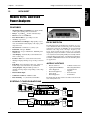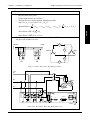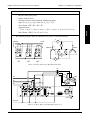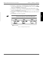
1
Model 6530 Three-Phase Power Analyzer User’s Manual Purchase Record Please record all model numbers and serial numbers of your Magtrol equipment, along with the general purchase information. The model number and serial number can be found on either a silver identification plate or white label affixed to each unit. Refer to these numbers whenever you communicate with a Magtrol representative about this equipment. Model Number: _____________________________ Serial Number: _____________________________ Purchase Date: _____________________________ Purchased From: _____________________________ While every precaution has been exercised in the compilation of this document to ensure the accuracy of its contents, Magtrol, Inc. assumes no responsibility for errors or omissions. Additionally, no liability is assumed for any damages that may result from the use of the information contained within this publication. Copyright Copyright ©2001-2005 Magtrol, Inc. All rights reserved. Copying or reproduction of all or any part of the contents of this manual without the express permission of Magtrol is strictly prohibited. Trademarks LabVIEW™ is a trademark of National Instruments Corporation. National Instruments™ is a trademark of National Instruments Corporation. Windows® is a registered trademark of Microsoft Corporation. 1st Edition, rev. F – November 2005 Safety Precautions 1. Make sure that all Magtrol dynamometers and electronic products are earth-grounded, to ensure personal safety and proper operation. 2. Securely ground the 6530 Power Analyzer case by connecting a good earth ground at the ground stud located on the rear panel of the unit. Use a number 12 AWG, or larger wire. 3. Check line voltage before operating. 4. Make sure that dynamometers and motors under test are equipped with appropriate safety guards. Revisions To This Manual The contents of this manual are subject to change without prior notice. Should revisions be necessary, updates to all Magtrol User’s Manuals can be found at Magtrol’s web site at www.magtrol.com/support/manuals.htm. Please compare the date of this manual with the revision date on the web site, then refer to the manual’s Table of Revisions for any changes/updates that have been made since this edition. Revision Date 1st Edition, Revision F – November 2005 Table of Revisions Date 11/03/05 11/03/05 08/10/05 09/30/03 06/19/03 06/19/03 06/19/02 05/20/02 05/20/02 11/26/01 11/26/01 11/26/01 11/05/01 Edition 1st Edition, Rev. F Change Corrected time it takes for a new input to fully average (0.07323388 ms –> 73.23388 ms). 1st Edition, Rev. F Updated crest factor and display range ratings. 1st Edition, Rev. E External sensor input maximum voltage from ±10 V to ±1 V AC/DC 1st Edition, Rev. D Correction: Line voltage - no setup required. 1st Edition, Rev. C Added configuration commands IS and IC to start/clear average mode. 1st Edition, Rev. C Added data output command OAVE to retrieve displayed values. 1st Edition, Rev. B Added analog output option information to data sheet. 1st Edition, Rev. A Changed mV/A to A/mV in External Sensor Scale Factor Setup Menu graphic 1st Edition, Rev. A Updated units and value range of SE1m2<terminator> command code 1st Edition Updated step 13 (setting amp range) of basic calibration process. 1st Edition Added "Frequency" to end of Data Position in OT Example. 1st Edition Product is primarily a three-phase instrument. A separate unit, the 6510e, has been developed for users who only require single-phase measurement capabilities. The 6530 manual has been updated to reflect this product change and a 6510e manual has been created. Preliminary Manual Updated values of MFm<terminator> command code. ii Section(s) 4.2.1.2 & 4.2.2.2 1.3 1.3, 2.5 3.1.1 5.6.1 5.6.2 1.3 3.3.3.2 5.6.1 6.4 5.4.1 1.2, 1.3 5.6.1 Table of Contents Safety Precautions..........................................................................................................................i Revisions To This Manual................................................................................................................ii Revision Date..................................................................................................................................................................ii Table of Revisions.......................................................................................................................................................ii Table of Contents...........................................................................................................................iii Table of Figures......................................................................................................................................................... vi Preface............................................................................................................................................... vii Purpose of This Manual........................................................................................................................................vii Who Should Use This Manual.............................................................................................................................vii Manual Organization............................................................................................................................................vii Conventions Used in This Manual................................................................................................................. viii 1. Introduction.................................................................................................................................1 1.1 Unpacking Your 6530 Power Analyzer........................................................................................................ 1 1.2 New Features of the 6530 Power Analyzer.............................................................................................. 1 1.3 Data Sheet................................................................................................................................................................. 2 2. Controls..........................................................................................................................................5 2.1 Front Panel.............................................................................................................................................................. 5 2.2 Front Panel Controls and Buttons........................................................................................................... 5 2.2.1 Enabling Secondary Functions..................................................................................................... 6 2.2.2 Using Front Panel Controls and Buttons............................................................................... 6 2.3 Vacuum Fluorescent Display (VFD)............................................................................................................. 8 2.3.1 Contrast Settings................................................................................................................................. 8 2.3.2 Display Guide............................................................................................................................................ 9 2.4 Rear Panel.............................................................................................................................................................. 10 2.5 Rear Panel Inputs and Outputs.................................................................................................................. 10 3. Installation/Configuration...................................................................................................13 3.1 Powering up the 6530......................................................................................................................................... 13 3.1.1 Line Voltage............................................................................................................................................ 13 3.1.2 Self-Test................................................................................................................................................... 13 3.1.3 Main Menu................................................................................................................................................ 14 3.2 Protecting Your 6530......................................................................................................................................... 15 3.2.1 Transient Overloads......................................................................................................................... 15 3.2.2 Current Overload.............................................................................................................................. 15 3.2.3 Surge Protection................................................................................................................................. 15 3.2.4 Circuit Breakers.................................................................................................................................. 16 3.3 Testing Instrumentation Setup.................................................................................................................. 17 3.3.1 Wiring Mode............................................................................................................................................ 17 3.3.2 Measurement Filter........................................................................................................................... 23 3.3.3 External Sensor.................................................................................................................................. 24 3.3.4 Amp Scaling............................................................................................................................................. 26 3.3.5 Volts Scaling......................................................................................................................................... 28 iii Table of Contents 3.3.6 3.3.7 Magtrol Model 6530 Three-Phase Power Analyzer Phase Setup.............................................................................................................................................. 29 Special Functions................................................................................................................................ 30 4. Operating Principles................................................................................................................32 4.1 Analog Processing............................................................................................................................................ 32 4.1.1 Volts........................................................................................................................................................... 32 4.1.2 Amps............................................................................................................................................................. 33 4.1.3 External Shunt.................................................................................................................................... 34 4.2 Digital Processing............................................................................................................................................. 34 4.2.1 AC Details................................................................................................................................................. 35 4.2.2 DC Details................................................................................................................................................. 37 4.2.3 Round-Off Error . ................................................................................................................................ 39 4.3 Measurement Modes......................................................................................................................................... 39 4.3.1 Peak ............................................................................................................................................................ 39 4.3.2 Peak Hold / Inrush Current............................................................................................................ 40 4.3.3 DC.................................................................................................................................................................. 40 4.3.4 RMS............................................................................................................................................................... 41 4.3.5 Crest Factor........................................................................................................................................... 41 4.4 Measurement Methods................................................................................................................................... 41 4.4.1 Cycle-by-Cycle Mode......................................................................................................................... 41 4.4.2 Continuous Mode................................................................................................................................. 41 5. Computer Controlled Operation.......................................................................................42 5.1 About the GPIB Interface............................................................................................................................... 42 5.1.1 Installing the GPIB/IEEE-488 Connector Cable..................................................................... 42 5.1.2 Changing the GPIB Primary Address.......................................................................................... 42 5.2 About the RS-232 Interface............................................................................................................................ 43 5.2.1 Connection.............................................................................................................................................. 43 5.2.2 Communication Parameters.......................................................................................................... 44 5.2.3 Baud Rate.................................................................................................................................................. 44 5.3 Checking the 6530-to-PC Connection........................................................................................................ 44 5.4 Data Format........................................................................................................................................................... 45 5.4.1OT Example . ............................................................................................................................................ 45 5.4.2OE Example ............................................................................................................................................. 46 5.4.3 OA/OV/OW/OF Example.......................................................................................................................... 46 5.5 Programming........................................................................................................................................................ 46 5.5.1 Data Termination Characters...................................................................................................... 46 5.6 6530 Communication Commands.................................................................................................................. 47 5.6.1 Configuration Commands............................................................................................................... 47 5.6.2 Data Output Commands.................................................................................................................... 50 6. Calibration...................................................................................................................................51 6.1 Closed-Box Calibration................................................................................................................................. 51 6.2 Calibration Schedule...................................................................................................................................... 51 6.3 Calibration Commands................................................................................................................................... 51 6.4Basic Calibration Process............................................................................................................................. 52 iv Table of Contents Magtrol Model 6530 Three-Phase Power Analyzer 7. Optional Features.....................................................................................................................54 7.1 Analog Outputs.................................................................................................................................................. 54 7.1.1 Specifications........................................................................................................................................ 54 7.1.2 Channel Assignments........................................................................................................................ 54 7.1.3Hardware Connection...................................................................................................................... 55 7.1.4 Software Configuration................................................................................................................. 55 7.1.5 Calibration............................................................................................................................................. 56 8. Troubleshooting........................................................................................................................58 Appendix A: Schematics................................................................................................................59 A.1Main Board - DSP, RAM, FLASH......................................................................................................................... 59 A.2main board - input/output, gpib, rs-232.................................................................................................... 60 A.3main board - fpga............................................................................................................................................... 61 A.4Input Module - Current.................................................................................................................................. 62 A.5Input Module - voltage................................................................................................................................... 63 A.6Key Pad..................................................................................................................................................................... 64 A.7Analog Output..................................................................................................................................................... 65 Glossary............................................................................................................................................69 Index......................................................................................................................................................70 Magtrol Limited Warranty..........................................................................................................72 Claims.............................................................................................................................................................................. 72 Service Information.......................................................................................................................73 Returning Magtrol equipment for Repair and/or Calibration...................................................... 73 Returning Equipment to Magtrol, Inc. (United States)................................................................. 73 Returning Equipment to Magtrol SA (Switzerland)...................................................................... 73 Table of Contents Magtrol Model 6530 Three-Phase Power Analyzer Table of Figures 2. Controls Figure 2–1 Figure 2–2 Figure 2–3 Figure 2–4 Figure 2–5 Figure 2–6 Figure 2–7 Front Panel ...............................................................................................................................................5 Secondary Function Menu.........................................................................................................................6 Device Setup Menu....................................................................................................................................8 Rear Panel...............................................................................................................................................10 Input Module...........................................................................................................................................10 RS-232C Interface...................................................................................................................................11 GPIB/IEEE-488 Interface.......................................................................................................................11 3. Installation/Configuration Figure 3–1 Program Download Display....................................................................................................................13 Figure 3–2 Title Display............................................................................................................................................13 Figure 3–3 Revision Display......................................................................................................................................14 Figure 3–4 Phase Main Menu....................................................................................................................................14 Figure 3–5 Summation Main Menu...........................................................................................................................14 Figure 3–6 Custom Main Menu.................................................................................................................................15 Figure 3–7 Transient Voltage Suppression.................................................................................................................16 Figure 3–8 Single-Phase, Two-Wire Wiring Schematic.............................................................................................18 Figure 3–9 Single-Phase, Two-Wire Wiring Connection...........................................................................................18 Figure 3-10 Single-Phase, Three-Wire Wiring Schematic..........................................................................................19 Figure 3–11 Single-Phase, Three-Wire Wiring Connection.......................................................................................19 Figure 3–12 Three-Phase, Three-Wire Wiring Schematic..........................................................................................20 Figure 3–13 Three-Phase, Three-Wire Wiring Connection........................................................................................20 Figure 3–14 Three-Phase, Four-Wire Wiring Schematic...........................................................................................21 Figure 3–15 Three-Phase, Four-Wire Wiring Connection.........................................................................................21 Figure 3–16 Three-Voltage, Three-Ampere Wiring Schematic...................................................................................22 Figure 3–17 Three-Voltage, Three-Ampere Wiring Connection.................................................................................22 Figure 3–18 Sensor Substitution Wiring Schematic...................................................................................................24 Figure 3–19 Sensor Substitution Wiring Connection.................................................................................................24 Figure 3–20 External Sensor Scale Factor Setup Menu............................................................................................25 Figure 3–21 Current/Potential Transformer Connection...........................................................................................26 Figure 3–22 Amp Scaling Setup Menu.......................................................................................................................26 Figure 3–23 Amp/Volt Scaling Activated...................................................................................................................27 Figure 3–24 Volt Scaling Setup Menu........................................................................................................................28 Figure 3–25 Cycle-by-Cycle Mode............................................................................................................................29 Figure 3–26 Hold Mode.............................................................................................................................................30 Figure 3–27 Average Mode........................................................................................................................................30 Figure 3–28 Peak Hold Clear Display.......................................................................................................................31 Figure 3–29 Custom Display.....................................................................................................................................31 4. Operating Principles Figure 4-1 Peak Example...........................................................................................................................................39 Figure 4–2 Peak Hold/Inrush Current Example........................................................................................................40 Figure 4–3 Crest Factor Example..............................................................................................................................41 5. Computer Controlled Operation Figure 5–1 Figure 5–2 Figure 5–3 Figure 5–4 Figure 5–5 GPIB Installation....................................................................................................................................42 GPIB Address Setup Menu......................................................................................................................43 RS-232 Interface......................................................................................................................................43 Cable Connection Using Null Modem....................................................................................................43 RS-232 Baud Rate Setup Menu...............................................................................................................44 6. Calibration Figure 6–1 Calibration/Verification Test Setup..........................................................................................................52 Figure 6–2 Calibration Mode Enabled......................................................................................................................52 7. Optional Features Figure 7–1 Analog Output.........................................................................................................................................54 Figure 7–2 Analog Output Setup Menu.....................................................................................................................55 vi Preface Purpose of This Manual This manual contains all the information required for the installation and general use of the Model 6530 Power Analyzer. To achieve maximum capability and ensure proper use of the instrument, please read this manual in its entirety before operating. Keep the manual in a safe place for quick reference whenever a question should arise. Who Should Use This Manual This manual is intended for those operators who are planning to use the Model 6530 Power Analyzer for power measurement purposes either as a stand-alone instrument or in conjunction with any Magtrol Hysteresis, Eddy-Current or Powder Brake Dynamometer, any Magtrol Dynamometer Controller and M-TEST Motor Testing Software. Manual Organization This section gives an overview of the structure of the manual and the information contained within it. Some information has been deliberately repeated in different sections of the document to minimize cross-referencing and to facilitate understanding through reiteration. The structure of the manual is as follows: Chapter 1: Introduction - Contains the technical data sheet for the 6530 Power Analyzer, which describes the unit and provides its mechanical and electrical characteristics. Chapter 2: CONTROLS - Description of the elements located on the front and rear panels of the unit. Chapter 3: Installation/Configuration - Provides information needed for setup of the 6530 including wiring mode, measurement filter, external sensor, amp scaling and volt scaling along with phase setup instructions and special functions available. Chapter 4:OPERATING PRINCIPLES - Information pertaining to theory of operation including analog processing, digital processing, measurement modes and measurement methods. Chapter 5: COMPUTER CONTROLLED OPERATION - How to run a test when the 6530 is used with a PC. Includes information on IEEE-488 and RS-232 Interface, data format, programming and command set. Chapter 6: Calibration - Provides recommended calibration schedules along with stepby-step instructions for the calibration procedure. Chapter 7: optional features - Provides information regarding various optional features available with the 6530 including analog outputs. Chapter 8: Troubleshooting - Solutions to common problems encountered during setup and testing. Appendix A: SCHEMATICS - For the main board, input modules, key pad and analog output. Glossary: List of abbreviations and terms used in this manual, along with their definitions. vii Preface Magtrol Model 6530 Three-Phase Power Analyzer Conventions Used in This Manual The following symbols and type styles may be used in this manual to highlight certain parts of the text: Note: This is intended to draw the operator’s attention to complementary information or advice relating to the subject being treated. It introduces information enabling the correct and optimal functioning of the product to be obtained. Caution: This is used to draw the operator’s attention to information, directives, procedures, etc. which, if ignored, may result in damage being caused to the material being used. The associated text describes the necessary precautions to take and the consequences that may arise if the precautions are ignored. WARNING! This introduces directives, procedures, precautionary measures, etc. which must be executed or followed with the utmost care and attention, otherwise the personal safety of the operator or third party may be put at risk. The reader must absolutely take note of the accompanying text, and act upon it, before proceeding further. viii 1.1 Introduction Unpacking Your 6530 Power Analyzer Your 6530 Power Analyzer was packaged in reusable, shock resistant packing material that will protect the instrument during normal handling. 1. Make sure the carton contains the following: model 6530 POWER ANALYZER enter display dC rms peak-Cf phase dC rms peak-Cf sourCe avg peak hold auto CyC-Cont W-va-pf hold auto Current range user menu shift voltage range 6530 Three-Phase Power Analyzer Line cord Magtrol User Manual CD-Rom Banana Jack Connectors (4 each per phase) Isolated BNC Sensor Connectors (1 each per phase) Calibration Certificate 2. Inspect the contents for any evidence of damage in shipping. In the event of shipping damage, immediately notify the carrier and Magtrol’s Customer Service Department. Note: Save all shipping cartons and packaging material for reuse when returning the instrument for calibration or servicing. 1.2New Features of the 6530 Power Analyzer Magtrol’s new Model 6530 Power Analyzer is an upgraded, three-phase version of the 6510. The new features that make the unit unique include: • • • • Analog Outputs: Plug-in module that provides 12 channels of analog output corresponding to volts, amps and watts. Peak Hold: Allows the unit to store the highest value read since the last peak hold was cleared. Values can include amps, watts and volts in any preferred combination. Average: Will average the volts, amps and watts over the period that the average function is enabled. Custom Readout: Display can be configured to present data in any desired format. GENERAL INFORMATION 1. Chapter 1 – Introduction M AGTROL Data Sheet 6510e/6530 Data Sheet Models 6510e and 6530 Power Analyzers Features • • • • • • • • • • • • • • • • • Single/Three-Phase Capabilities: For single (6510e) or three-phase (6530) power measurements Ranges: Up to 600 Vrms @ 20 A continuous duty Interfaces: RS-232 & IEEE-488 Data Transfer Rates: Up to 100 per second Accuracy: Up to 0.1% Vacuum Fluorescent Display: High-quality, easy-toread, customizable readout displays volts, amps, power and power factor Measurement: Continuous or cycle-by-cycle Bandwidth: DC up to 100 kHz Input Power: Accepts 120/240 Vrms, 60/50 Hz power at 20 VA max Auto Ranging: Automatically scales instrument for most accurate range Isolation: 1000 Vrms to earth, 750 Vrms line-to-line Average: Displays running average of amps, volts and watts Peak Hold: Stores the highest value read. Values can include amps, watts and volts in any combination Analog Outputs: Plug-in module provides 12 channels of analog output corresponding to volts, amps and watts External Shunt Input Calibration Certificate: NIST Traceable Rack Mounting: 19” (482.6 mm) with handles DesCription The Magtrol 6510e and 6530 Power Analyzers are easyto-use instruments ideal for numerous power measurement applications. From DC to 100 kHz AC, the 6510e/6530 measures volts, amps, watts, volt-amps, frequency, crest factor, Vpeak, Apeak and power factor in one convenient display.They may be used either as stand-alone instruments or in conjunction with any Magtrol Hysteresis, Eddy-Current or Powder Brake Dynamometer; any Magtrol Dynamometer Controller and M-TEST Software for more demanding motor test applications. appliCations • • • • • • Motors and Drives Lighting Fixtures/Ballasts Office Equipment Household Appliances Power Tools HVAC Equipment • • • • Calibration of Test and Measuring Instruments Switching Power Supplies Power Inverters Transformers The 6510e’s/6530’s data transfer rate makes it ideal for both static and dynamic tests. system ConFigurations Motor Under Test MODEL DSP6001 POWER TORQUE SPEED BRAKE STATUS SET POINT SET POINT DYNAMOMETER CONTROLLER STATUS POWER P I D DSP6001 Dynamometer Controller VOLTS AMPS 750 V MAX. 20 A MAX. V 20 A MAX. AMPS 750 V MAX. 20 A MAX. A N A L O G A ±± ± 1000 V MAX. EXT. SENSOR ±10 V MAX. VOLTS AV V 1000 V MAX. AC/DC Input Power ± O U T P U T 1000 V MAX. EXT. SENSOR ±10 V MAX. EXT. SENSOR ±10 V MAX. 20VA 50/60Hz EARTH GROUND PC GPIB/IEEE-488 RS-232C MAGTROL INC. AMPS V A N A L O G A 750 V MAX. 20 A MAX. ± ± O U T P U T 1000 V MAX. AC/DC Input Power GPIB Card CAUTION: DOUBLE POLE FUSING EXT. SYNC. M-TEST 120V UL/CSA 250mA 250V SB 240V IEC 160mA 250V T FUSE (5x20mm) MODEL 6530 THREE-PHASE POWER ANALYZER VOLTS Appliances, Ballasts, Drives, etc. AMPS 750 V MAX. ±± ±± Magtrol Dynamometer VOLTS AV ± EXT. SENSOR ±10 V MAX. CAUTION: DOUBLE POLE FUSING RS-232 or GPIB PC 20VA 50/60Hz EARTH GROUND EXT. SYNC. GPIB/IEEE-488 RS-232C MAGTROL INC. 120V UL/CSA 250mA 250V SB 240V IEC 160mA 250V T FUSE (5x20mm) MODEL 6510e SINGLE-PHASE POWER ANALYZER www.magtrol.com GENERAL INFORMATION 1.3 Magtrol Model 6530 Three-Phase Power Analyzer Chapter 1 – Introduction Magtrol Model 6530 Three-Phase Power Analyzer 6510e/6530 VOLTAGE INPUT CURRENT INPUT EXTERNAL SENSOR INPUT Ranges 30 V, 150 V, 300 V, 600 V 1 A, 5 A, 10 A, 20 A 50 mV, 250 mV, 500 mV, 1 V Maximum Voltage 750 V AC/DC terminal (V) 1000 V AC/DC ±1 V AC/DC to terminal (±) and terminal to ground 1000 V AC/DC terminal to earth ground Crest Factor 1.7 @ full scale input 2.7 @ full scale input 2.4 @ full scale input Impedance 2 M7 12 M7 17 M7 Display Range 5 digits with 1 mV 5 digits with 1 mA 5 digits with 1 µV resolution resolution resolution ACCURACY DC ±(0.1% Reading + 0.2% Range) 5 Hz – 500 Hz ±(0.1% Reading + 0.1% Range) 500 Hz – 10 kHz ±((0.015 × F(kHz)% Reading) + 0.3% Range) 10 kHz – 100 kHz ±((0.015 × F(kHz)% Reading) + 0.3% Range) > 100 kHz POWER --------5 digits with 1 mW resolution 0.4% of VA range 0.2% of VA range 0.6% of VA range 0.6% + (0.03% × F(kHz)% of VA range) N/A (measurement band limited to DC–100 kHz) Source Accuracy EXT. Input Input Impedance Voltage Level Maximum Voltage FREQUENCY V1, A1, V2, A2, V3, A3, LINE or EXT (For Vx and Ax, source input must be >10% of range setting) 20 Hz to 500 Hz; 0.05% BNC non-isolated, earth ground referenced 100 k7 TTL / CMOS 50 V DIMENSIONS Width 19.0 in 483 mm Height 3.5 in 89 mm Depth 12.4 in 315 mm with handles 13.8 in 351 mm Weight 12.97 lb 5.88 kg Front Panel Ready for Rack Mounting Custom Display Setup Phase and Summation Data Amp Readings (DC, RMS, Peak, Crest Factor and Peak Hold/Inrush) Current Auto Ranging Volt Readings (DC, RMS, Peak, Crest Factor and Peak Hold/Inrush) Voltage Auto Ranging Continuous or Cycle-by-Cycle Measurement Mode Cycle-by-Cycle Synchronized Source Averaging of Volts, Amps and Watts Holds Current Value Calculate Watts, Vrms × Arms and Power Factor rear Panel Phase Input Module 3 for 6530 (as shown), 1 for 6510e External Sensor Input External Sync. Input (Cycle-by-Cycle Synchronization) Voltage Input RS-232C and GPIB/IEEE-488 Interfaces (for Connection to Personal Computer) Optional Analog Output Current Input (not shown) M AGTROL GENERAL INFORMATION Specifications Chapter 1 – Introduction Magtrol Model 6530 Three-Phase Power Analyzer 6510e/6530 analog output option external shunts/sensors The Analog Output is a plug-in module designed specifically for use with the 6510e Single-Phase Power Analyzer and 6530 Three-Phase Power Analyzer.It provides up to 12 channels (3 for the 6510e, 12 for the 6530) of analog output corresponding to volts, amps and watts. Each output is capable of, and calibrated to, ± 10 volts.With the analog output option, the user may apply a scale factor to all outputs.Amps scaling is applied to all amp channels, volts scaling is applied to all volt channels and watts scaling is applied to all watt channels. If currents continuously reach above 20 amps, an external sensor must be used. Magtrol offers three different types of external shunts for use with Magtrol models 6510e or 6530 High-Speed Power Analyzers. Other features include: • • • • Simple Installation: Plug-in module automatically configures power analyzer for operation Frequent Output Updates: Updates every 5 milliseconds Output Short Protected Factory Calibrated: Calibration data/values stored on board (EEPROM) Industry Standard 25-Pin Connection The Analog Output can be used along with a 6510e or 6530 Power Analyzer to output information to a strip recorder or interface with a data acquisition system.The Analog Output is also used as a safety feature to help trigger alarm events. SPECIFICATIONS 14 bits 4 ppm FSR/°C (typical), Temperature Coefficient 20 ppm FSR/°C (maximum) Output Range ± 10 V maximum 3 (6510e) Number of Channels 12 (6530) Basic Accuracy 3 least significant bits Output Update Rate 200 samples/second (5 ms) (all channels) Resolution Available Models The HA Series shunt, designed for Series P/N Amps power cable hook-up utilizing3/8- HA 004640 50 16 screws, has an insulating base HA 004641 100 and can be mounted on conductive HA 004642 150 surfaces. The LAB Series shunt HA 004643 200 also comes with an insulating base, HA 004644 250 along with thumb screws for the HA 004645 300 power leads and knurled nuts on the HA 004646 400 sensing terminals.The FL Series is HA 004647 500 a relatively small bus, bar-mounted LAB 004648 750 shunt with large end blocks. The LAB 004649 1000 comparatively large end blocks and FL 005214 2000 short spacing aid in cooling and FL 005286 3000 allow the shunt to operate in more extreme environments.All shunts are calibrated on equipment with current certifications traceable to N.I.S.T. SPECIFICATIONS HA Series LAB Series FL Series Rated Current 50 to 500 A 750 to 1000 A 2000 to 3000 A Output 50 mV Bandwidth DC to 60 Hz ± 0.25% Accuracy (± 0.1% accuracy with calibration certificate is available for an additional cost) Operating Temperature For optimum accuracy, temperature of shunt should be 30 °C to 70 °C Sensor Substitution Wiring Connection VOLTS AMPS 750 V MAX. 20 A MAX. V A N A L O G A ± ± O U T P U T 1000 V MAX. EXT. SENSOR ±10 V MAX. orDering inFormation Single-Phase Power Analyzer 20VA 50/60Hz EARTH GROUND GPIB/IEEE-488 RS-232C MAGTROL INC. 120V UL/CSA 250mA 250V SB 240V IEC 160mA 250V T FUSE (5x20mm) 6510e Single-Phase Power Analyzer EARTH HIGH MOV LOW 6510e-01 Single-Phase Power Analyzer with Analog Output Option CB ± 6530 Three-Phase Power Analyzer 6530-01 Three-Phase Power Analyzer with Analog Output Option LOAD 6510e CAUTION: DOUBLE POLE FUSING EXT. SYNC. A SHUNT (HA Series) NOTE: For the 6530 Three-Phase Analyzer, any (or all) of the Amps inputs may be replaced with a shunt for any of the wiring modes. Due to the continual development of our products, we reserve the right to modify specifications without forewarning. www.magtrol.com magtrol inC 70 Gardenville Parkway Buffalo, New York 14224 USA Phone: +1 716 668 5555 Fax: +1 716 668 8705 E-mail: [email protected] magtrol sa Centre technologique Montena 1728 Rossens / Fribourg, Switzerland Phone: +41 (0)26 407 3000 Fax: +41 (0)26 407 3001 E-mail: [email protected] Subsidiaries in: • Germany • France • Great Britain • China Worldwide Network of Sales Agents 6510e6530-US 06/06 • GENERAL INFORMATION Options and Accessories 2.1 Front Panel The front panel provides a power switch, sixteen control buttons and a Vacuum Fluorescent Display (VFD). model 6530 POWER ANALYZER enter display dC rms peak-Cf phase dC rms peak-Cf sourCe avg peak hold auto CyC-Cont W-va-pf hold auto Current range shift user menu voltage range Figure 2–1 Front Panel 2.2Front Panel Controls and Buttons The front panel controls and buttons, from left to right, are: • Power switch • Ten double-function control buttons: Primary Function PHASE q CURRENT RANGE p CURRENT RANGE AUTO CURRENT RANGE q VOLTAGE RANGE p VOLTAGE RANGE AUTO VOLTAGE RANGE CYC-CONT W-VA-PF HOLD • • Secondary Function DISPLAY DC (current) RMS (current) PEAK-CF (current) DC (voltage) RMS (voltage) PEAK-CF (voltage) SOURCE AVG PEAK HOLD SHIFT - enables secondary functions printed in blue above control buttons Five USER MENU buttons • Left Arrow • Right Arrow • Up Arrow • Down Arrow • ENTER GENERAL INFORMATION 2. Controls Chapter 2 – Controls Enabling Secondary Functions To enable the secondary function of the double-function control buttons: 1. Press the blue SHIFT button and release it. The word “SHIFT” appears in the display: CURRENT VOLTAGE POWER/PF Figure 2–2 Secondary Function Menu 2. Press any control button to enable the function shown in blue letters above the button. 2.2.2 Using Front Panel Controls and Buttons 2.2.2.1 Controls/Single-Function Buttons Button POWER SHIFT ENTER t u p q To Use Function Press I to turn power ON Press Turns power ON or OFF. O to turn power OFF. Press this button and release; Enables the function written in blue above then press desired control control button. button. User Menu Press this button. Enables/Disables USER MENU. Press this button. When USER MENU is enabled, toggles between fields, selections or the digits in a numerical value. Press this button. When USER MENU is enabled, toggles between fields, selections or the digits in a numerical value. Press this button. When USER MENU is enabled, toggles between selections or increases the selected digit of a numerical value. Press this button. When USER MENU is enabled, toggles between selections or decreases the selected digit of a numerical value. GENERAL INFORMATION 2.2.1 Magtrol Model 6530 Three-Phase Power Analyzer Chapter 2 – Controls Magtrol Model 6530 Three-Phase Power Analyzer Double-Function Buttons Button DISPLAY PHASE DC RMS PEAK-CF q p AUTO DC RMS PEAK-CF q p AUTO SOURCE CYC-CONT To Use Function Press SHIFT and release; then Shows custom display. press this button. (For further instruction, see Section 3.3.7.4 - Custom Display.) Press this button. Toggles through phase 1, 2, 3 and summation. Current Press SHIFT and release; then Selects DC amps measurement. press this button. Press SHIFT and release; then Selects RMS amps measurement. press this button. Press SHIFT and release; then Selects displayed amps measurement. press this button. Continue to press SHIFT then PEAK-CF and the displayed values toggle through the following: • Acf (amps crest factor readings) • A~↑ (amps peak hold/inrush readings) • Apk (amps peak readings) Current Range Press this button. Decrements amps range. Press this button. Increments amps range. Press this button. Selects/deselects amps auto range. Voltage Press SHIFT and release; then Selects DC voltage measurement. press this button. Press SHIFT and release; then Selects RMS voltage measurement. press this button. Press SHIFT and release; then Selects displayed voltage measurement. press this button. Continue to press SHIFT then PEAK-CF and the displayed values toggle through the following: • Vcf (voltage crest factor readings) • V~↑ (voltage peak hold/inrush readings) • Vpk (voltage peak readings) Voltage Range Press this button. Decrements voltage range. Press this button. Increments voltage range. Press this button. Selects/deselects voltage auto range. Press SHIFT and release; then Selects the signal that the cycle-by-cycle press this button. measurement will be synchronized with. Continue to press SHIFT then SOURCE and the source toggles through the following: • V1, V2, V3 (voltage input) • A1, A2, A3 (amps input) • EXT (external sync input) • LINE (incoming AC line) NOTE: Selecting SHIFT then SOURCE will automatically switch unit to cycle-by-cycle mode. Press this button. Selects continuous or cycle-by-cycle measurement method. GENERAL INFORMATION 2.2.2.2 Chapter 2 – Controls Magtrol Model 6530 Three-Phase Power Analyzer W-VA-PF PEAK HOLD HOLD 2.3 To Use Function Press SHIFT and release; then Enables averaging mode. press this button. Press this button. Selects what calculated value is to be displayed.Continue to press W-VA-PF and the displayed values toggle through the following: • W↑ (inrush watts) • W (watts) • VA (Vrms × Arms) • PF (power factor) Press SHIFT and release; then Resets peak hold/inrush values. press this button. Press this button. Holds displayed values until hold is pressed again. NOTE: All internal machine functions will be halted except auto-ranging when the HOLD feature is enabled. Vacuum Fluorescent Display (VFD) The VFD provides information about the control functions, phase voltages and currents. Top Row Current Voltage Power/PF 2.3.1 Bottom Row Current Range Voltage Range Source/Status Contrast Settings The 6530 Power Analyzer is shipped with the Contrast Setting on low in order to prolong display life. If it is necessary to increase the Contrast for improved readability, execute the following steps using the USER MENU located on the front panel of the unit. 1. Press the ENTER button. The display should appear as follows: CURRENT VOLTAGE DEVICE POWER/PF SELECTIONS Figure 2–3 Device Setup Menu 2. Press and buttons until "I/O" appears in the display. 3. Press ENTER button. 4. Press and buttons until "DISPLAY BRIGHTNESS" appears in the display. 5. Use the and buttons until desired brightness is reached. 6. Press ENTER button to return to main menu. Note: There are three settings available; low, medium and high. Make GENERAL INFORMATION Button AVG Chapter 2 – Controls Magtrol Model 6530 Three-Phase Power Analyzer 2.3.2 Display Guide Following is a reference for symbols, abbreviations and messages that are used in the 6530. Symbol/Abbreviation/Message SHIFT I/O ERROR V A W PF pk cf 1 2 3 ã ¹ l Σ ↑ … ~ Meaning Shift button was pressed Command not recognized Volts Amps Watts Power Factor Peak Crest Factor Phase 1 Phase 2 Phase 3 Scaling function is activated Average function is activated Peak Hold/Inrush function is activated Summation Peak Hold/Inrush DC RMS (AC+DC) GENERAL INFORMATION sure the lowest possible setting is used to achieve desired result. Using a setting higher than necessary may cause display segments to burn-in over a period of time, resulting in uneven illumination from segment to segment. Chapter 2 – Controls Rear Panel The rear panel provides connectors and receptacles for connecting to appropriate equipment. 2 VOLTS AMPS V VOLTS AMPS AV 20 A MAX. 20 A MAX. ±± 1000 V MAX. EXT. SENSOR ±1 V MAX. 750 V MAX. 20 A MAX. ±± ± 1000 V MAX. A N A L O G A ± ±± ± 750 V MAX. 3 AMPS AV V 750 V MAX. VOLTS EXT. SENSOR ±1 V MAX. CAUTION: DOUBLE POLE FUSING 20VA 50/60Hz EARTH GROUND EXT. SYNC. O U T P U T 1000 V MAX. EXT. SENSOR ±1 V MAX. 5 GPIB/IEEE-488 RS-232C MAGTROL INC. Figure 2–4 Rear Panel 1 120V UL/CSA 250mA 250V SB 240V IEC 160mA 250V T FUSE (5x20mm) 4 6 7 2.5Rear Panel Inputs and Outputs 1 INPUT MODULE Contains the Voltage Input, Current Input and External Sensor connectors for each phase. VOLTS AMPS 750 V MAX. 20 A MAX. V 1a A ± 1b ± 1000 V MAX. 1c EXT. SENSOR ±1 V MAX. Figure 2–5 Input Module 1a Voltage Input Connect wires to measure voltage across the load (parallel). Caution: V oltage should not exceed 750 V AC/DC terminal (V) to terminal (±) and 1000 V AC/DC terminal to earth ground. 1b Current Input 1c External Sensor Connect wires to measure amps through the load (series). Caution: Amps should not exceed 20 A continuous. Voltage should not exceed 1000 V AC/DC terminal to ground. Alternate amps input for current sensor or shunt. Caution: Voltage should not exceed ±1 V AC/DC. 10 GENERAL INFORMATION 2.4 Magtrol Model 6530 Three-Phase Power Analyzer Chapter 2 – Controls Magtrol Model 6530 Three-Phase Power Analyzer 3 ANALOG OUTPUT (optional) Connects strip chart recorder or data acquisition system. Provides 12 analog outputs, 3 for each phase and 3 for summation. • Volts 1, 2, 3, Σ • Amps 1, 2, 3, Σ • Watts 1, 2, 3, Σ ±10 volts = range See Section 7.1 – Analog Outputs for detailed information about this option. EXT. SYNC. Provides alternate method to synchronize the power analyzer with the measured signal in cycle-by-cycle mode. 4 RS-232C Caution: Input is not isolated from earth ground. Ext. Sync. should not exceed 0–5 V DC (TTL/CMOS Levels). Use this socket for RS-232 connector cable. 5 4 9 3 8 2 7 1. 2. RX 3. TX 4. 5. GND 1 6 6. 7. 8. 9. Figure 2–6 RS-232C Interface 5 GPIB/ IEEE-488 Use this socket for GPIB cable (meets IEEE-488 specifications). 12 11 10 9 8 7 6 5 4 3 2 1 24 23 22 21 20 19 18 17 16 15 14 13 1. D1 2. D2 3. D3 4. D4 5. E01 6. DAV 7. NRFD 8. NDAC 9. IFC 10. SRQ 11. ATN 12. SHIELD 13. D5 14. D6 15. D7 16. D8 17. REN 18. DAV-COM 19. NRFD-COM 20. NDAC-COM 21. IFC-COM 22. SRQ-COM 23. ATN-COM 24. SIGNAL GROUND Figure 2–7 GPIB/IEEE-488 Interface 11 GENERAL INFORMATION 2 Chapter 2 – Controls 7 POWER Attach power cord here. EARTH GROUND Attach earth ground here. WARNING: 12 MAKE SURE THAT ALL MAGTROL DYNAMOMETERS AND ELECTRONIC PRODUCTS ARE EARTH-GROUNDED, TO ENSURE PERSONAL SAFETY AND PROPER OPERATION. SECURELY GROUND THE 6530 POWER ANALYZER CASE BY CONNECTING A GOOD EARTH GROUND AT THE GROUND STUD LOCATED ON THE REAR PANEL OF THE UNIT. USE A NUMBER 12 AWG, OR LARGER WIRE. GENERAL INFORMATION 6 Magtrol Model 6530 Three-Phase Power Analyzer 3. Installation/Configuration Note:Before installing the 6530, you should become familiar with the front and rear panels, as outlined in Chapter 2 – Controls. 3.1Powering up the 6530 3.1.1 Warning! To reduce the risk of electric shock, Make sure the 6530 is earth grounded before starting! Line Voltage The 6530 will operate from 85 to 264 VAC on a 50/60 Hz line voltage. 3.1.2 Self-Test After turning the power on to the 6530, the display panel will show all segments of the VFD (series of rectangles), indicating that the 6530 is downloading the program. CURRENT VOLTAGE POWER/PF Figure 3–1 Program Download Display When the program download is complete, the Title Display will appear. CURRENT VOLTAGE Figure 3–2 Title Display 13 POWER/PF SETUP Chapter 3 – Installation/Configuration Magtrol Model 6530 Three-Phase Power Analyzer Then an additional display will appear indicating the version of your Magtrol 6530 Power Analyzer. CURRENT VOLTAGE POWER/PF Figure 3–3 Revision Display SETUP 3.1.3 Main Menu When the 6530 is completely powered up and ready for use, the main menu will appear on the display. The main menu is defined by the last configuration that was used. This could include one of three different menus: phase, summation or custom. The phase menu could be a representation of phase 1, 2 or 3 and will appear as follows. CURRENT VOLTAGE POWER/PF Figure 3–4 Phase Main Menu The summation menu contains information pertaining to all 3 phases. The voltage value represents an average of the 3 phases and the amps and watts values represent the sum of the phases. CURRENT VOLTAGE Figure 3–5 Summation Main Menu 14 POWER/PF Chapter 3 – Installation/Configuration Magtrol Model 6530 Three-Phase Power Analyzer The custom menu can include up to 6 fields with selections dependent on the measurement mode. CURRENT VOLTAGE POWER/PF Figure 3–6 Custom Main Menu SETUP 3.2Protecting Your 6530 Before the 6530 is used for power measurement, guidelines regarding transient overloads, current overload, surge protection and circuit breakers must be followed. 3.2.1 Transient Overloads Connect an appropriate transient suppressor in parallel with all inductive loads. Consult the suppressor vendor’s application literature for proper selection and sizing. Caution: Damage to the 6530 can result from excessive voltage transients generated by unsuppressed inductive loads. This damage is not within the scope of the normal instrument service and is not covered by the Magtrol Warranty. 3.2.2 Current Overload There are no fuses in the 6530 measuring circuits. Therefore, excessive current passed through the amps terminals will cause excessive internal heating and possible unit damage. Caution: This overload abuse is not covered by the Magtrol Warranty. Know your load conditions and double check all connections. If an overload should occur, immediately remove all power and locate and correct the problem before re-energizing your circuit. If a circuit breaker is installed, it must be installed on the load side of the 6530 (downstream). This will keep the low impedance of the input line connected to the 6530 for surge suppression. If the line side must also contain a breaker, it should be delayed in operation to open after the load side breaker has opened. 3.2.3 Surge Protection Use Metal Oxide Varistors (MOV) or other equivalent transient suppressors connected between lines at the load (across the load). These suppressors are an absolute necessity when inductive loads are used. In three-phase systems, each load must have a suppressor. 15 Chapter 3 – Installation/Configuration Magtrol Model 6530 Three-Phase Power Analyzer VMOV > VLINE TO LINE (LINE 1) L1 VMOV > 1 3 V LINE TO LINE (LINE 1) L1 (LOAD) MOV (LOAD) MOV MOV MOV NEUTRAL L2 L2 L3 DELTA CONNECTED THREE-PHASE LOAD WYE CONNECTED THREE-PHASE LOAD VMOV > VLINE TO LINE (LINE) LINE HIGH (LOAD) MOV LINE LOW SINGLE PHASE TWO-WIRE LOAD Figure 3–7 Transient Voltage Suppression 3.2.4 Circuit Breakers With the circuits described in Section 3.3.1.1 - Hardware Connections, use the 6530 remote voltage sense by measuring the voltage at the load. This increases measurement accuracy by eliminating line voltage drop from the power measurement. For safety, an overload circuit breaker removes all load voltage during an over-current condition. The voltage sense lines are connected at the line side of the circuit breaker to help prevent inductive transients from entering the 6530 as the circuit breaker opens. Make sure that connections from the circuit breaker to the load are heavy conductors and short as possible. Caution: If a circuit breaker is used in the input line to the 6530, a circuit should be used that prevents the breaker from opening until after the load side breaker has opened. Otherwise, potentially damaging inductive transients can be applied to the 6530. Damage caused by these transients are outside the scope of the Magtrol Warranty. 16 SETUP MOV MOV L3 Chapter 3 – Installation/Configuration Magtrol Model 6530 Three-Phase Power Analyzer 3.3 Testing Instrumentation Setup Before the 6530 can be utilized, it must be configured and connected to the devices intended for power measurement. 3.3.1 Wiring Mode The 6530 has the ability to support a combination of up to 3 phases, therefore, there are a number of different ways in which the unit can be wired. 3.3.1.1 Hardware Connections SETUP The wiring mode selections include: • 1-Phase, 2-Wire • 1-Phase, 3-Wire • 3-Phase, 3-Wire • 3-Phase, 4-Wire • 3-Volt, 3-Amp The following pages provide more detail on the power measurement, as well as wiring connection diagrams and schematics, of the different wiring modes. Note: Active Power is the sum of the instantaneous volts multiplied by the instantaneous amps inputs. Apparent Power is the product of volts root mean square and amps root mean square. 17 Chapter 3 – Installation/Configuration Magtrol Model 6530 Three-Phase Power Analyzer 1-Phase, 2-Wire Measures single-phase power. Can be wired on any input module. The Power Factor is derived from the following equations: Amps Σ = Ax, Volts Σ = Vx Active Power = WØ Apparent Power = VrmsØ × ArmsØ = VØ AØ • Power Factor = WØ / VØ AØ (Where Ø is the phase of operation) Most commonly used for single phase AC and DC motor applications. SETUP • • • The following diagrams show the connections for a 1-Phase, 2-Wire measurement. Only one phase has been shown for clarity, but any of the three phases may be used. SOURCE LOAD V ± V A SOURCE ± V ± A A LOAD ± Ø1, Ø2, Ø3 Figure 3–8 Single-Phase, Two-Wire Wiring Schematic VOLTS AMPS V VOLTS AMPS AV 750 V MAX. 20 A MAX. ± 750 V MAX. 20 A MAX. A N A L O G A 750 V MAX. 20 A MAX. ±± 1000 V MAX. EXT. SENSOR ±10 V MAX. AMPS AV ±± 1000 V MAX. VOLTS ± O U T P U T 1000 V MAX. EXT. SENSOR ±10 V MAX. EXT. SENSOR ±10 V MAX. CAUTION: DOUBLE POLE FUSING 20VA 50/60Hz EARTH GROUND EXT. SYNC. GPIB/IEEE-488 RS-232C 120V UL/CSA 250mA 250V SB 240V IEC 160mA 250V T FUSE (5x20mm) MAGTROL INC. EARTH LOW HIGH CB Figure 3–9 Single-Phase, Two-Wire Wiring Connection 18 LOAD MOV LINE Chapter 3 – Installation/Configuration Magtrol Model 6530 Three-Phase Power Analyzer 1-Phase, 3-Wire Measures single-phase power. Utilizes input modules one and three. The Power Factor is derived from the following equations: Amps Σ = (A1 + A3)/2, Volts Σ = (V1 + V3)/2 Active Power = ΣW = W1 + W3 Apparent Power = (Vrms1 × Arms1) + (Vrms3 × Arms3) = V1 A1 + V3 A3 Power Factor = ΣW/( V1 A1 + V3 A3) The following diagrams show the connections for a 1-Phase, 3-Wire measurement. Notice that only phase one and three are used. SOURCE A LOAD A1 ± V L1 N L2 V1 N V ± A V ± ± ± LOAD SOURCE A ± ± V3 V Ø1 A Ø3 A3 ± N CB LOAD L1 MOV LOAD Figure 3-10 Single-Phase, Three-Wire Wiring Schematic MOV L2 VOLTS AMPS V VOLTS AMPS AV 750 V MAX. 20 A MAX. ± 750 V MAX. 20 A MAX. ±± 1000 V MAX. AMPS A N A L O G A 750 V MAX. 20 A MAX. ±± 1000 V MAX. EXT. SENSOR ±10 V MAX. VOLTS AV ± O U T P U T 1000 V MAX. EXT. SENSOR ±10 V MAX. EXT. SENSOR ±10 V MAX. CAUTION: DOUBLE POLE FUSING 20VA 50/60Hz EARTH GROUND EXT. SYNC. GPIB/IEEE-488 RS-232C MAGTROL INC. 120V UL/CSA 250mA 250V SB 240V IEC 160mA 250V T FUSE (5x20mm) EARTH Figure 3–11 Single-Phase, Three-Wire Wiring Connection 19 SETUP • • • Chapter 3 – Installation/Configuration Magtrol Model 6530 Three-Phase Power Analyzer 3-Phase, 3-Wire • • • Measures three-phase power. Utilizes input modules one and three. The Power Factor is derived from the following equations: Amps Σ = (A1 + A3)/2, Volts Σ = (V1 + V3)/2 Apparent Power = 3 2 ( (V rms1 ) 3 (V1 A 1 + V3 A 3 ) 2 × A rms1 ) + (Vrms3 × A rms3 ) = 3 SETUP Active Power = ΣW = W1 2 + W3 / Power Factor = ΣW ( V1 A1 + V3 A3) The following diagrams show the connections for a 3-Phase, 3-Wire measurement. Notice that only phase one and three are used. SOURCE A LOAD R S T ± A1 V R V1 SOURCE V A V A ± ± ± ± T LOAD ± S ± V3 Ø1 Ø3 A V A3 ± Figure 3–12 Three-Phase, Three-Wire Wiring Schematic LINE Ø1 LOAD MOV Ø2 MOV CB LO AD AD LO Ø3 MOV VOLTS AMPS V VOLTS AMPS AV 750 V MAX. 20 A MAX. ± 750 V MAX. 20 A MAX. ±± 1000 V MAX. AMPS 750 V MAX. 20 A MAX. A N A L O G A ±± 1000 V MAX. EXT. SENSOR ±10 V MAX. VOLTS AV ± O U T P U T 1000 V MAX. EXT. SENSOR ±10 V MAX. EXT. SENSOR ±10 V MAX. CAUTION: DOUBLE POLE FUSING 20VA 50/60Hz EARTH GROUND EXT. SYNC. GPIB/IEEE-488 RS-232C MAGTROL INC. 120V UL/CSA 250mA 250V SB 240V IEC 160mA 250V T FUSE (5x20mm) EARTH Figure 3–13 Three-Phase, Three-Wire Wiring Connection 20 Chapter 3 – Installation/Configuration Magtrol Model 6530 Three-Phase Power Analyzer 3-Phase, 4-Wire Measures three-phase power. Utilizes all three phases. The Power Factor is derived from the following equations: Amps Σ = (A1 + A2 + A3)/3, Volts Σ = (V1 + V2 + V3)/3 Active Power = ΣW = W1 + W2 + W3 Apparent Power = (Vrms1 × Arms1) + (Vrms2 × Arms2) + (Vrms3 × Arms3) = V1 A1 + V2 A2 + V3 A3 Power Factor = ΣW/( V1 A1 + V2 A2 + V3 A3) SETUP • • • The following diagrams show the connections for 3-Phase, 4-Wire measurement. SOURCE R S T N V ± A LOAD ± A1 V V1 R SOURCE A V ± A ± V ± ± T A ± S ± ± V3 ± V A Ø1 Ø2 LOAD A Ø3 V2 A2 V ± A3 ± Figure 3–14 Three-Phase, Four-Wire Wiring Schematic CB LOAD MOV Ø3 LO AD Ø2 AD LO Ø1 MOV MOV VOLTS AMPS V VOLTS AMPS AV 750 V MAX. 20 A MAX. ± 750 V MAX. 20 A MAX. ±± 1000 V MAX. AMPS 750 V MAX. 20 A MAX. A N A L O G A ±± 1000 V MAX. EXT. SENSOR ±10 V MAX. VOLTS AV ± O U T P U T 1000 V MAX. EXT. SENSOR ±10 V MAX. EXT. SENSOR ±10 V MAX. CAUTION: DOUBLE POLE FUSING 20VA 50/60Hz EARTH GROUND EXT. SYNC. GPIB/IEEE-488 RS-232C MAGTROL INC. 120V UL/CSA 250mA 250V SB 240V IEC 160mA 250V T FUSE (5x20mm) EARTH NEUTRAL Figure 3–15 Three-Phase, Four-Wire Wiring Connection 21 Chapter 3 – Installation/Configuration Magtrol Model 6530 Three-Phase Power Analyzer 3-Volt, 3-Amp • • • Measures three-phase power. Utilizes all three phases. The Power Factor is derived from the following equations: Amps Σ = (A1 + A2 + A3)/3, Volts Σ = (V1 + V2 + V3)/3 Active Power = Σ 3 = W1 + W3 3 ) / Power Factor = ΣW ( V1 A1 + V2 A2 + V3 A3) Most common hookup for three-phase motors. • The following diagrams show the connections for a 3-Volt, 3-Amp measurement. SOURCE A LOAD R S T A1 ± V SOURCE V A V A V A ± ± ± ± ± ± T R V V1 ± S A2 A V2 LOAD ± ± ± V3 Ø1 Ø2 A Ø3 A3 V ± Figure 3–16 Three-Voltage, Three-Ampere Wiring Schematic CB LOAD MOV Ø3 MOV LO AD Ø2 AD LO Ø1 MOV VOLTS AMPS V VOLTS AMPS AV 750 V MAX. 20 A MAX. ± 750 V MAX. 20 A MAX. ±± 1000 V MAX. AMPS 750 V MAX. 20 A MAX. A N A L O G A ±± 1000 V MAX. EXT. SENSOR ±10 V MAX. VOLTS AV ± O U T P U T 1000 V MAX. EXT. SENSOR ±10 V MAX. EXT. SENSOR ±10 V MAX. CAUTION: DOUBLE POLE FUSING 20VA 50/60Hz EARTH GROUND EXT. SYNC. GPIB/IEEE-488 RS-232C MAGTROL INC. 120V UL/CSA 250mA 250V SB 240V IEC 160mA 250V T FUSE (5x20mm) EARTH Figure 3–17 Three-Voltage, Three-Ampere Wiring Connection 22 SETUP ( 3 3 Vrms1 × A rms1) + (Vrms2 × A rms2 ) + (Vrms3 × A rms3) = ( (V A + V A +V A ) 3 3 1 1 2 2 3 3 Apparent Power = Chapter 3 – Installation/Configuration Magtrol Model 6530 Three-Phase Power Analyzer 3.3.1.2 Software Configuration To configure the 6530 to coincide with the wiring on the rear panel, complete the following steps utilizing the USER MENU located on the front panel of the unit. 1. Turn on the 6530. See Section 3.1 – Powering Up the 6530. 2. Press ENTER button. The display should appear as shown in Figure 2–3 Device Setup Menu. 3. Press and buttons until WIRING MODE appears in the display. 4. Press and buttons until desired wiring mode is reached. 5. Press ENTER to exit Device Setup Menu. SETUP 3.3.2 Measurement Filter During the RMS calculations, in the signal-processing path, there is a digital low-pass filter. The user can program the filter’s cutoff frequency. Measured Value • • (Value)² Filter Square Root Selections include 1 Hz, 2 Hz, 5 Hz, 10 Hz, 20 Hz, 50 Hz and 100 Hz . Correlation between filter setting and response is as follows: Filter Setting Low High Response to Signal Change Outcome Slow Stable Reading Fast Unstable Reading For more detailed information on theory, see Chapter 4 – Operating Principles. 3.3.2.1 Hardware Connection Not applicable. 3.3.2.2 Software Configuration To configure the 6530 measurement filter, complete the following steps utilizing the USER MENU located on the front panel of the unit. 1. Turn on the 6530. See Section 3.1 – Powering Up the 6530. 2. Press ENTER button. The display should appear as shown in Figure 2–3 Device Setup Menu. 3. Press and buttons until MEASUREMENT FILTER appears in the display. 4. Press and buttons until desired measurement filter is reached. 5. Press ENTER to exit Device Setup Menu. 23 Chapter 3 – Installation/Configuration 3.3.3 Magtrol Model 6530 Three-Phase Power Analyzer External Sensor If currents continuously reach above 20 amps, an external sensor must be used. 3.3.3.1 Hardware Connection In any of the wiring modes, any one of the amp meters may be replaced. The following diagram illustrates the connection. A ± A A A ± V A ± ± SETUP = COAXIAL CABLE Figure 3–18 Sensor Substitution Wiring Schematic VOLTS AMPS V VOLTS AMPS AV 750 V MAX. 20 A MAX. ± VOLTS AMPS 750 V MAX. 20 A MAX. AV 750 V MAX. 20 A MAX. ±± ±± 1000 V MAX. 1000 V MAX. EXT. SENSOR ±10 V MAX. A N A L O G A ± O U T P U T 1000 V MAX. EXT. SENSOR ±10 V MAX. EXT. SENSOR ±10 V MAX. CAUTION: DOUBLE POLE FUSING 20VA 50/60Hz EARTH GROUND EXT. SYNC. GPIB/IEEE-488 RS-232C MAGTROL INC. 120V UL/CSA 250mA 250V SB 240V IEC 160mA 250V T FUSE (5x20mm) EARTH HIGH LOW CB ± A SHUNT Figure 3–19 Sensor Substitution Wiring Connection 24 LOAD MOV Chapter 3 – Installation/Configuration Magtrol Model 6530 Three-Phase Power Analyzer 3.3.3.2 Software Configuration To configure the 6530 external sensor, complete the following steps utilizing the USER MENU located on the front panel of the unit. 1. Turn on the 6530. See Section 3.1 – Powering Up the 6530. 2. Press ENTER button. The display should appear as shown in Figure 2–3 Device Setup Menu. 3. Press and buttons until EXTERNAL SENSOR appears in the display. 4. Press ENTER button. The display will appear as follows. VOLTAGE POWER/PF Figure 3–20 External Sensor Scale Factor Setup Menu 5. To set the scale factor for A1, press the RMS button under A1 and use the buttons in the USER MENU to adjust the value. 6. To set the scale factor for A2, press the RMS button under A2 and use the buttons in the USER MENU to adjust the value. 7. To set the scale factor for A3, press the AVG button under A3 and use the buttons in the USER MENU to adjust the value. 8. Press ENTER to exit the Device Setup Menu. 25 SETUP CURRENT Chapter 3 – Installation/Configuration 3.3.4 Magtrol Model 6530 Three-Phase Power Analyzer Amp Scaling The current measurement range can be extended by using a current transformer. Frequency response will be determined by the characteristics of the transformer used. 3.3.4.1 Hardware Connection VOLTS AMPS V VOLTS AMPS AV 750 V MAX. 20 A MAX. ± 750 V MAX. 20 A MAX. ±± 1000 V MAX. AMPS A N A L O G A 750 V MAX. 20 A MAX. ±± 1000 V MAX. ± O U T P U T 1000 V MAX. EXT. SENSOR ±10 V MAX. EXT. SENSOR ±10 V MAX. CAUTION: DOUBLE POLE FUSING 20VA 50/60Hz EARTH GROUND EXT. SYNC. GPIB/IEEE-488 RS-232C 120V UL/CSA 250mA 250V SB 240V IEC 160mA 250V T FUSE (5x20mm) MAGTROL INC. SETUP EXT. SENSOR ±10 V MAX. VOLTS AV EARTH MOV 2 MOV 3 PT CT LOW MOV 1 HIGH LOAD LINE CB Figure 3–21 Current/Potential Transformer Connection 3.3.4.2 Software Configuration To configure the 6530 amp scaling for a current transformer, complete the following steps utilizing the USER MENU located on the front panel of the unit. 1. Turn on the 6530. See Section 3.1 – Powering Up the 6530. 2. Press ENTER button. The display should appear as shown in Figure 2–3 Device Setup Menu. 3. Press and buttons until AMP SCALING appears in the display. 4. Press ENTER button. The display will appear as follows. CURRENT VOLTAGE POWER/PF Figure 3–22 Amp Scaling Setup Menu 5. To set the amp scaling for phase 1, press the RMS button under A1 and use the buttons in the USER MENU to adjust the value. 26 Chapter 3 – Installation/Configuration Magtrol Model 6530 Three-Phase Power Analyzer 6. To turn phase 1 scaling ON, press the PEAK-CF button under OFF until ON is reached. 7. To set the amp scaling for phase 2, press the RMS button under A2 and use the buttons in the USER MENU to adjust the value. 8. To turn phase 2 scaling ON, press the PEAK-CF button under OFF until ON is reached. 9. To set the amp scaling for phase 3, press the AVG button under A3 and use the buttons in the USER MENU to adjust the value. 10. To turn phase 3 scaling ON, press the PEAK HOLD button under OFF until ON is reached. 11. Press ENTER to exit the Device Setup Menu. Note: When amps scaling has been activated, “*” will appear in the main menu next to the ampsrange as shown in the following figure. CURRENT VOLTAGE SCALING ACTIVATED Figure 3–23 Amp/Volt Scaling Activated 27 POWER/PF SETUP Chapter 3 – Installation/Configuration 3.3.5 Magtrol Model 6530 Three-Phase Power Analyzer Volts Scaling The voltage measurement range can be extended by using a potential transformer. Frequency response will be determined by the characteristics of the transformer used. 3.3.5.1 Hardware Connection See Figure 3–21 Current/Potential Transformer Connection. 3.3.5.2 Software Configuration CURRENT VOLTAGE POWER/PF Figure 3–24 Volt Scaling Setup Menu 5. To set the volt scaling for phase 1, press the RMS button under V1 and use the buttons in the USER MENU to adjust the value. 6. To turn phase 1 scaling ON, press the PEAK-CF button under OFF until ON is reached. 7. To set the volt scaling for phase 2, press the RMS button under V2 and use the buttons in the USER MENU to adjust the value. 8. To turn phase 2 scaling ON, press the PEAK-CF button under OFF until ON is reached. 9. To set the volt scaling for phase 3, press the AVG button under V3 and use the buttons in the USER MENU to adjust the value. 10. To turn phase 3 scaling ON, press the PEAK HOLD button under OFF until ON is reached. 11. Press ENTER to exit the Device Setup Menu. Note: When volts scaling has been activated, “*” will appear in the main menu next to the volts range as shown in Figure 3–23 Amp/Volt Scaling Activated. 28 SETUP To configure the 6530 volt scaling for a potential transformer, complete the following steps utilizing the USER MENU located on the front panel of the unit. 1. Turn on the 6530. See Section 3.1 – Powering Up the 6530. 2. Press ENTER button. The display should appear as shown in Figure 2–3 Device Setup Menu. 3. Press and buttons until VOLT SCALING appears in the display. 4. Press ENTER button. The display will appear as follows. Chapter 3 – Installation/Configuration Magtrol Model 6530 Three-Phase Power Analyzer 3.3.6 Phase Setup CURRENT VOLTAGE POWER/PF SOURCE READING Figure 3–25 Cycle-by-Cycle Mode 29 SETUP Once the wiring mode, measurement filter, external sensor, amp scaling and volt scaling have been connected and configured, the unit is ready to be configured for each individual phase. 1. To select phase, press PHASE button until desired phase is reached. 2. Select current measurement mode (DC, RMS, peak, crest factor or peak hold). a. To select DC press SHIFT and release, then press DC button located in CURRENT RANGE section of front panel. b. To select RMS press SHIFT and release, then press RMS button located in CURRENT RANGE section of front panel. c. To select peak, crest factor or peak hold, press SHIFT and release, then press PEAK-CF button located in CURRENT RANGE section of front panel. Keep pressing SHIFT and PEAK-CF buttons until desired selection appears in display. For more information on peak, crest factor and peak hold, see Section 4.3 – Measurement Modes. 3. Select current range by using the and buttons located in CURRENT RANGE section of front panel. Selections include 50 mV, 250 mV, 0.5 V and 1 V when using an external sensor and 1 A, 5 A, 10 A and 20 A when using amps input. 4. Select voltage measurement mode (DC, RMS, peak, crest factor or peak hold). a. To select DC press SHIFT and release, then press DC button located in VOLTAGE RANGE section of front panel. b. To select RMS press SHIFT and release, then press RMS button located in VOLTAGE RANGE section of front panel. c. To select peak, crest factor or peak hold, press SHIFT and release, then press PEAK-CF button located in VOLTAGE RANGE section of front panel. Keep pressing SHIFT and PEAK-CF buttons until desired selection appears in display. For more information on peak, crest factor and peak hold, see Section 4.3 – Measurement Modes. 5. Select voltage range by using the and buttons located in VOLTAGE RANGE section of front panel. Selections include 30 V, 150 V, 300 V and 600 V. 6. Press W-VA-PF button until desired selection is reached. Selections include Wx↑, Wx, VAx and PFx where “x” is equivalent to the selected phase. 7. Repeat steps 1-6 for each phase. 8.Once the individual phases have been configured, cycle-by-cycle or continuous must be chosen. See Section 4.4 – Measurement Methods. a.1.For cycle-by-cycle mode, press CYC-CONT button until display shows source reading in lower right corner similar to the following figure. Chapter 3 – Installation/Configuration Magtrol Model 6530 Three-Phase Power Analyzer a.2.A source now needs to be selected. Press SHIFT button and release, then press SOURCE button. Keep repeating until desired source selection is reached. Selections include V1, A1, V2, A2, V3, A3, EXT and LINE. b. For continuous mode, press CYC-CONT until display does not show any readings in the lower right corner. Special Functions 3.3.7.1 Hold • • Freezes display values. To set, press and release HOLD button. The display will appear as follows, indicating that the hold function is enabled. CURRENT VOLTAGE POWER/PF HOLD MODE INDICATORS Figure 3–26 Hold Mode • 3.3.7.2 To disable, press and release HOLD button. Average • Mode in which the power analyzer displays the running average of amps, volts and watts. • Used to stabilize mildly fluctuating readings or to determine watt-hours when used in conjunction with a timer. • To set, press SHIFT button and release, then press AVG. The display will appear as follows, indicating that the Average Function is enabled. CURRENT VOLTAGE AVERAGE MODE INDICATORS Figure 3–27 Average Mode • To disable, press SHIFT button and release, then press AVG. 30 POWER/PF SETUP 3.3.7 Chapter 3 – Installation/Configuration Magtrol Model 6530 Three-Phase Power Analyzer 3.3.7.3 Peak Hold • Clears peak hold/inrush reading. • To enable, press SHIFT button and release, then press PEAK HOLD. The display will flash the following, then return to the main menu. CURRENT VOLTAGE POWER/PF SETUP Figure 3–28 Peak Hold Clear Display 3.3.7.4 Custom Display • The display can be configured to present data in any format. • To set, press SHIFT button and release, then press DISPLAY. The display will appear as follows. CURRENT VOLTAGE POWER/PF Figure 3–29 Custom Display • There are 6 fields in the display that can be customized with information based on previous individual phase setups. To set, from the USER MENU control buttons, toggle from field to field by using the and buttons and make selections using the and buttons. If there is not a preferred value for a specific field, press ENTER when the field is selected and it will be deleted from the display. 31 4. Operating Principles 4.1 Analog Processing 4.1.1 Volts The volts signal is brought in through a precision voltage divider of 2 M and 2.4 k resistors. The gain is 0.0012. This signal is buffered (GAIN = 1) and passed into a programmable gain section. The gains for the voltage ranges are given below. Range 30 V 150 V 300 V 600 V Resistors 12 k / 620 2.4 k / 620 1.2 k / 620 620 / 620 Gain ( Amplifier ) -19.350 -3.871 -1.936 -1.000 Range 30 V 150 V 300 V 600 V Volts In (VDC) 3 30 15 150 30 300 60 600 Gain (total) -0.023220 -0.023220 -0.004645 -0.004645 -0.002323 -0.002323 -0.001200 -0.001200 Volts at A/D Input -0.0697 -0.6966 -0.0697 -0.6968 -0.0697 -0.6969 -0.0720 -0.7200 Converter Resolution: 2.5 / 2^16 = 2.5 / 65536 = 0.00003814697 32 Bits 1826 18261 1826 18265 1827 18269 1887 18874 THEORY The signal is then presented to an AD7722AS 16-bit analog to digital converter. The part accepts an input signal of ± 1.25 volts centered on a 2.5 VDC volt bias. The chart below shows system input at 10% and 100% of range. Chapter 4 – Operating Principles Magtrol Model 6530 Three-Phase Power Analyzer 4.1.2 Amps The amps signal is brought in through a precision shunt of 0.012 ohms. This signal is amplified by 2 and passed into a programmable gain section. The gains for the voltage ranges are given below. Range 1A 5A 10 A 20 A Resistors 12 k / 620 2.4 k / 620 1.2 k / 620 620 / 620 Gain ( Amplifier ) -19.350 -3.871 -1.936 -1.000 The signal is then presented to an AD7722AS 16-bit analog to digital converter. The part accepts an input signal of ± 1.25 volts centered on a 2.5 VDC volt bias. The chart below shows system input at 10% and 100% of range. Range 1A 10 A 20 A Shunt Volts First Stage Amp 0.0012 -0.0024 0.0120 -0.0240 0.0060 -0.0120 0.0600 -0.1200 0.0120 -0.0240 0.1200 -0.2400 0.0240 -0.0480 0.2400 -0.4800 Gain -19.35000 -19.35000 -3.87100 -3.87100 -1.93600 -1.93600 -1.00000 -1.00000 Converter Resolution: 2.5 / 2^16 = 2.5 / 65536 = 0.00003814697 Shunt resistance = 0.012 33 Volts at A/D Input 0.0464 0.4644 0.0465 0.4645 0.0465 0.4646 0.0480 0.4800 Bits 1217 12174 1218 12177 1218 12180 1258 12583 THEORY 5A Amps In (ADC) 0.1 1.0 0.5 5.0 1.0 10.0 2.0 20.0 Chapter 4 – Operating Principles 4.1.3 Magtrol Model 6530 Three-Phase Power Analyzer External Shunt The external shunt signal is brought in through a precision voltage divider of 9.1 k and 9.1 k resistors. The gain is 0.50. This signal is buffered and passed into a programmable gain section. The gains for the voltage ranges are given below. Range 50 mV 250 mV 500 mV 1000 mV Resistors 12 k / 620 2.4 k / 620 1.2 k / 620 620 / 620 Gain ( Amplifier ) -19.350 -3.871 -1.936 -1.000 The signal is then presented to an AD7722AS 16-bit analog to digital converter. The part accepts an input signal of +/- 1.25 volts centered on a 2.5 VDC volt bias. The chart below shows system input at 10% and 100% of range. Range 50 mV 500 mV 1000 mV Gain (total) -9.67500 -9.67500 -1.93550 -1.93550 -0.96800 -0.96800 -0.50000 -0.50000 Volts at A/D Input -0.0484 -0.4838 -0.0484 -0.4839 -0.0484 -0.4840 -0.0500 -0.5000 Converter Resolution: 2.5 / 2^16 = 2.5 / 65536 = 0.00003814697 4.2 Digital Processing Bits 1268 12681 1268 12684 1269 12688 1311 13107 Starting at the AD7722AS analog to digital converter, the input clock to the device is 14.31818 MHz. This clock frequency gives a sample rate or data output rate of 14318180 / 64 = 223721.5625 samples per second. The DSP processor uses fractional data representation for all Data ALU operations. Using long words (48-bit) the most negative number that can be represented is -1 ($800000000000). The most positive number that can be represented is 1 – 2-47 ($7FFFFFFFFFFF). Example: $123456 (Hex integer) 0001 0010 0011 0100 0101 0110 (Binary) 0.142222166 (Fractional) 34 THEORY 250 mV Volts In (VDC) 0.005 0.050 0.025 0.250 0.050 0.500 0.100 1.000 Chapter 4 – Operating Principles Magtrol Model 6530 Three-Phase Power Analyzer 4.2.1 AC Details 4.2.1.1 Interrupt Driven The power analyzer will automatically update its data every 4.469 microseconds by completing the following sequence of events: • The volts input is read and checked for an over range condition. The offset is then added to the reading and the reading is negated and saved. • The amps input is read and checked for an over range condition. The offset is then added to the reading and the reading is negated and saved. • The volt reading is checked to see if it is the peak and if so is stored. • The amp reading is checked to see if it is the peak and if so is stored. • The volt reading is squared and the squared reading is summed. • The volt and amp reading is multiplied and the multiplied value is summed. • The amp reading is squared and summed. Note: 35 THEORY After 256 readings are summed, the sums are transferred to a 56-bit V² register, a 56-bit VI register, and a 56-bit I² register. A sample ready flag is set. Chapter 4 – Operating Principles 4.2.1.2 Magtrol Model 6530 Three-Phase Power Analyzer Main Program The main program reads that a sample is ready. Divide the V² register by 256. Store V² in a 24-bit register. (See Section 4.2.3 – Round-Off Error). The result is appended to a 32 word circular buffer. Add buffer contents and divide by 32. The result is appended to a 2cd 32 word circular buffer. Divide the I² register by 256. Store I² in a 24-bit register. The result is appended to a 32 word circular buffer. Add buffer contents and divide by 32. The result is appended to a 2cd 32 word circular buffer. Add 2cd V² buffer contents and divide by 32. Save this value. Add 2cd I² buffer contents and divide by 32. Save this value. Add 2cd VI buffer contents and divide by 32. Save this value. Each sample is now 256 X (32 + 32) (16384) a/d samples. At 223721.5625 samples per second that is 73.23388 ms for a new input to fully average. The VI sample is applied to an RC filter algorithm. The output of the filter is multiplied by a gain value. This value is stored for output. The V² sample is applied to an RC filter algorithm. The square root of the output is taken. The result is multiplied by a gain value. This value is stored for output. The I² sample is applied to an RC filter algorithm. The square root of the output is taken. The result is multiplied by a gain value. This value is stored for output. These values are updated at 873.912 readings per second. Every 8th time through the loop or at a rate of 109.239 the V and I peak values are stored for output and the data ready flag is set. 36 THEORY Divide VI register by 256. Store VI in a 24-bit register. The result is appended to a 32 word circular buffer. Add buffer contents and divide by 32. The result is appended to a 2cd 32 word circular buffer. Chapter 4 – Operating Principles Magtrol Model 6530 Three-Phase Power Analyzer 4.2.2 DC Details 4.2.2.1 Interrupt Driven The power analyzer will automatically update its data every 4.469 microseconds by completing the following sequence of events: • The volts input is read and checked for an over range condition. The offset is then added to the reading and the reading is negated and saved. • The amps input is read and checked for an over range condition. The offset is then added to the reading and the reading is negated and saved. • The volt reading is checked to see if it is the peak and if so, is stored. • The amp reading is checked to see if it is the peak and if so, is stored. • The volt reading is summed. • The amp reading is summed. • The volt and amp reading is multiplied. • The multiplied value is summed. Note: After 256 readings are summed the sums are transferred to a 56-bit V register, a 56-bit I register, and a 56-bit VI register. A sample ready flag is set. 37 THEORY Chapter 4 – Operating Principles 4.2.2.2 Magtrol Model 6530 Three-Phase Power Analyzer Main Program The main program reads that a sample is ready. Divide the V register by 256. Store V in a 24-bit register. The result is appended to a 32 word circular buffer. Add buffer contents and divide by 32. The result is appended to a 2cd 32 word circular buffer. Divide the I register by 256. Store I in a 24-bit register. The result is appended to a 32 word circular buffer. Add buffer contents and divide by 32. The result is appended to a 2cd 32 word circular buffer. Add 2cd V2 buffer contents and divide by 32. Save this value. Add 2cd I2 buffer contents and divide by 32. Save this value. Add 2cd VI buffer contents and divide by 32. Save this value. Each sample is now 256 X (32 + 32) (16384) a/d samples. At 223721.5625 samples per second that is 73.23388 ms for a new input too fully average. The VI sample is applied to an RC filter algorithm. The output of the filter is multiplied by a gain value. This value is stored for output. The V sample is applied to an RC filter algorithm. The output of the filter is multiplied by a gain value. This value is stored for output. The I sample is applied to an RC filter algorithm. The output of the filter is multiplied by a gain value. This value is stored for output. These values are updated at 873.912 readings per second. Every 8th time through the loop or at a rate of 109.239 the V and I peak values are stored for output and the data ready flag is set. 38 THEORY Divide the VI register by 256. Store VI in a 24-bit register. The result is appended to a 32 word circular buffer. Add buffer contents and divide by 32. The result is appended to a 2cd 32 word circular buffer. Chapter 4 – Operating Principles Magtrol Model 6530 Three-Phase Power Analyzer 4.2.3 Round-Off Error The interrupt routine adds 256 56-bit squared readings. This reading is then divided by 256 and put into a 24-bit register. Some error occurs during the move to the 24-bit register. The result of the 16-bit A/D conversion is put into the high 16 bits of a 24-bit register. Example 1: A/D reading = 56-bit register = Square of 56-bit = Store to 24-bit = 000B 00 000B00 000000 (0.0003357) 00 000000 F20000 (0.00000012269) 000000 (0.0000000) Example 2: A/D reading = 56-bit register = Square of 56-bit = Store to 24-bit = 000C 00 000C00 000000 (0.0003662) 00 000001 200000 (0.00000013411) 000001 4.3 Measurement Modes 4.3.1 Peak The graph below shows one cycle of a repetitive waveform. The peak value is shown. The absolute value of the reading is used to determine the peak value. VOLTS vs. ANGLE 250 Peak 200 150 100 50 0 0 50 100 150 200 250 300 350 -50 volts -100 Figure 4-1 Peak Example 39 THEORY The peak value is defined as the highest value that occurs in the cycle of a repetitive waveform. Chapter 4 – Operating Principles 4.3.2 Magtrol Model 6530 Three-Phase Power Analyzer Peak Hold / Inrush Current Peak hold/inrush current allows the 6530 to store the highest value read in a designated period of time, the designated period of time being the time span since the last peak hold clear occurred. Values include amps, watts and volts in any preferred combination. See Section 3.3.7.3 – Peak Hold. The graph below shows the current draw from a 1/3 horsepower motor during initial startup. At startup the current inrush peaks at about 14 amps then settles to 4.25 amps. When the unit is in peak hold/ inrush mode of operation, the front panel current reading displays 14.033 amps. The current reading indicates the peak inrush current, which is determined by the RMS value. The operation of the volts and watts peak hold follows the same operation as explained for the current above. THEORY Figure 4–2 Peak Hold/Inrush Current Example 4.3.3 DC See Section 4.2.2 – DC Details. 40 Chapter 4 – Operating Principles Magtrol Model 6530 Three-Phase Power Analyzer 4.3.4 RMS See Section 4.2.1 – AC Details 4.3.5 Crest Factor The crest factor measurement is determined by dividing the peak measurement by the RMS measurement. See the following graph for reference. 1.5 RMS 0.707 Volts 1 0.5 -0.5 0 50 100 150 200 250 300 350 CF = Peak / RMS CF = 1/0.707 = 1.41 -1 Peak 1Volt volts volts² VRMS -1.5 Figure 4–3 Crest Factor Example 4.4 Measurement Methods 4.4.1 Cycle-by-Cycle Mode In the cycle-by-cycle mode the power analyzer looks at each complete cycle of the incoming waveform. The measurements are valid from 20 Hz to 500 Hz. The power analyzer may be synchronized from any of the phase volts or amps inputs, the line voltage or the back panel external sync input. If using volts or amps for synchronization, the input must be greater than 10% of the range setting. 4.4.2 Continuous Mode In the continuous mode the measurement values are determined from continuously processed and filtered volts and amps input values. The measurements are valid from DC to 100 kHz and the output data rate from the process is about 109.24 samples per second. The power analyzer does not have to be synchronized to the measured waveform and the user may select the filter to be used in the mean process of the RMS value. 41 THEORY 0 5. Computer Controlled Operation Using the 6530 with a personal computer (PC) enables the unit to perform at its full capacity. 5.1About the GPIB Interface Magtrol prefers the GPIB (General Purpose Interface Bus)/IEEE-488 Standard for computer-toinstrument interfacing because: • The GPIB parallel interface is faster than serial interfaces. • The GPIB enables testers to access up to 15 instruments on one port. Because typical motor testing requires that at least five separate parameters be synchronized, a system of easy, fast access to more than one instrument is essential. • The GPIB has rigid data formatting and hardware standards. These standards help to ensure that all functions will work properly when the hardware and software are installed. Note: 5.1.1 The GPIB interface is not standard on most personal computers. An interface card and driver software must be installed. An IEEE-488 cable must also be installed between the computer and the 6530. Magtrol recommends National Instruments Corporation hardware and software. Installing the GPIB/IEEE-488 Connector Cable Caution: Make 6530 installing the GPIB connector cable. sure both the computer and are turned off before 1. Connect one end of a high-quality, double-shielded cable to the 6530 GPIB connector. 2. Connect the other end to the GPIB interface in your PC. PC VOLTS AMPS V VOLTS AMPS AV 20 A MAX. 750 V MAX. 20 A MAX. ±± ± 1000 V MAX. EXT. SENSOR ±10 V MAX. A 750 V MAX. 20 A MAX. ±± ± ±± 1000 V MAX. AMPS AV V 750 V MAX. ± VOLTS 1000 V MAX. EXT. SENSOR ±10 V MAX. EXT. SENSOR ±10 V MAX. A N A L O G O U T P U T CAUTION: DOUBLE POLE FUSING 20VA 50/60Hz EARTH GROUND EXT. SYNC. Magtrol Test and Measurement Software GPIB/IEEE-488 RS-232C MAGTROL INC. 120V UL/CSA 250mA 250V SB 240V IEC 160mA 250V T FUSE (5x20mm) Figure 5–1 GPIB Installation 5.1.2 Changing the GPIB Primary Address Each instrument serviced by the GPIB has its own primary address code, which enables the computer to obtain readings from the instrument. The factory default of the GPIB address on the 6530 is 14. Some PC interfaces can access from one to fifteen 4-bit primary addresses. Other interfaces can 42 OPERATION Chapter 5 – Computer Controlled Operation Magtrol Model 6530 Three-Phase Power Analyzer access as many as thirty-one 5-bit primary addresses. The 6530 uses the 4-bit format. For setup, complete the following instructions utilizing the USER MENU control buttons. 1. Press ENTER. 2. Use the and buttons until I/O is reached. 3. Press ENTER. 4. Use the and buttons until GPIB ADDRESS is reached. The display should appear as follows: CURRENT VOLTAGE POWER/PF Figure 5–2 GPIB Address Setup Menu 5. Use the and buttons until desired primary address is reached (range 0-15). 6. Press ENTER to return to main menu. 5.2About the RS-232 Interface The 6530 is equipped with an RS-232 (serial) interface that communicates with the host computer through a DB-9 interface connector. The connector pin-out consists of 2-RX, 3-TX and 5-GND. 5 4 3 8 1. 2. RX 3. TX 4. 5. GND 2 7 1 6 OPERATION 9 6. 7. 8. 9. Figure 5–3 RS-232 Interface 5.2.1 Connection The RS-232 requires null modem wiring. To install use a null modem connector cable, which can be purchased from your local electronics store. 6530 PC RX TX GND DIGITAL GROUND 1. 2. 3. 4. 5. 6. 7. 8. 9. 1. 2. 3. 4. 5. 6. 7. 8. 9. DCD (DATA CARRIER DETECT) RX (RECEIVE DATA) TX (TRANSMIT DATA) DTR (DATA TERMINAL READY) GND (SIGNAL GROUND) DSR (DATA SET READY) RTS (REQUEST TO SEND) CTS (CLEAR TO SEND) RI (RING INDICATOR) Figure 5–4 Cable Connection Using Null Modem 43 Chapter 5 – Computer Controlled Operation 5.2.2 Communication Parameters • No parity • 8 data bits • 1 stop bit 5.2.3 Baud Rate Magtrol Model 6530 Three-Phase Power Analyzer There are several different baud rates to choose from including 300, 600, 1200, 2400, 4800, 9600, 19200 and 115200. To set up the desired baud rate, complete the following instructions utilizing the USER MENU control buttons. 1. Press ENTER. 2. Use the and buttons until I/O is reached. 3. Press ENTER. 4. Use the and buttons until RS-232 BAUDRATE is reached. The display should appear as follows: CURRENT VOLTAGE POWER/PF Figure 5–5 RS-232 Baud Rate Setup Menu 5.3 Checking the 6530-to-PC Connection Note: Make sure that the 6530 and its host computer are communicating before acquiring data. 1. Make sure the primary GPIB address is set correctly for the 6530. 2. Set the input variable to 15 characters (13 variable characters and the two required data termination characters CR and LF. See Section 5.5 – Programming.) Desired Results • Note: output_string = “6530 R 1.16”<delimiter> If the desired results did not occur, please see Chapter 8 – Troubleshooting. 3. Issue output data command “*IDN?” and read 15 characters according to the instructions for your GPIB interface or serial. 44 OPERATION 5. Use the and buttons until desired baud rate is reached. 6. Press ENTER to return to main menu. Chapter 5 – Computer Controlled Operation Magtrol Model 6530 Three-Phase Power Analyzer 5.4 Data Format • • • All measurement values are returned as an ASCII-string floating point in E notation. The same data format will be used for both IEEE-488 and RS-232 interface. See Section 5.6 – 6530 Communication Commands. Data is separated by commas. Character \s \r \n ^ Definition space carriage return line feed Located in the first returned character position indicating peak input value is above range, user needs to increase range. NOTE: If a space is located in the first returned character position, the input signal is within range and no changes need to be made. Sections 5.4.1 through 5.4.3 contain return data format examples for the following: •Output Total (OT) •Output Volts (OV) •Output Element (OE) •Output Watts (OW) •Output Amps (OA) •Output Frequency (OF) 5.4.1 OT Example Total = 183 characters Output String: (1-182) = measurement value float E notation (ANSI) Data Position: A1, V1, W1, A2, V2, W2, A3, V3, W3, ∑A, ∑V, ∑W, Frequency Good Response \s\s1.86707E-01,\s\s1.19568E+02,\s\s1.32201E+01,\s-1.10599E-03,\s-3.28546E-02,\s\ s0.00000E+00,\s-3.17532E-04,\s\s4.00554E-02,\s\s0.00000E+00,\s\s6.18068E-02,\s\s3.98861E+01,\ s\s1.32390E+01,\s\s5.99982E+01\r\n 5.4.1.2 Over-Range Condition \s\s1.85048E-01,^\s4.94537E+01,^\s4.20193E+00,\s-1.08896E-03,\s-3.04530E-02,\ s\s0.00000E+00,\s-3.81305E-04,\s\s4.70035E-02,\s\s0.00000E+00,\s\s6.14162E-02,^\ s1.65010E+01,^\s4.23552E+00,\s\s5.99860E+01\r\n 45 OPERATION 5.4.1.1 Chapter 5 – Computer Controlled Operation 5.4.2 Magtrol Model 6530 Three-Phase Power Analyzer OE Example Total = 43 characters Output String: (1-42) = measurement value float E notation (ANSI) Data Position: Ax, Vx, Wx (where x = requested phase) 5.4.2.1 Good Response \s\s1.83352E-01,\s\s1.19342E+02,\s\s1.29812E+01\r\n 5.4.2.2 Over-Range Condition \s\s1.84250E-01,^\s4.95238E+01,^\s4.26064E+00\r\n 5.4.3 OA/OV/OW/OF Example Total = 15 characters Output String: (1-14) = measurement value float E notation (ANSI) 5.4.3.1 Good Response \s\s1.19494E+02\r\n 5.4.3.2 Over-Range Condition ^\s4.94796E+01\r\n Programming 5.5.1 Note: Check the manual provided with your software for full instructions. Data Termination Characters Use the following information to answer the formatting questions asked when installing your GPIB software. All GPIB data acquisition systems require the use of data termination characters. The 6530 uses the GPIB standard termination characters Carriage Return (CR) and Line Feed (LF). Provide them in that order. 5.5.1.2 Codes for CR-LF CR = LF = BASIC CHR$(13) CHR$(10) 46 HEX OD OA DEC 13 10 OPERATION 5.5 Chapter 5 – Computer Controlled Operation Magtrol Model 6530 Three-Phase Power Analyzer 5.6 6530 Communication Commands IEEE-488 Address: Terminator: 0-15 carriage return followed by a line feed RS-232Baud Rate: Terminator: 300, 600, 1200, 2400, 4800, 9600, 19.2 k, 115.2 k carriage return followed by a line feed When entering a command code: 1. Type all characters in uppercase ASCII format. 2. End all commands with a carriage return followed by a line feed. 3. Do not string multiple commands together in one line. 5.6.1 Note: If a command is not recognized, the I/O ERROR message will appear in the Status Display accompanied by a beep. Configuration Commands Command Code *IDN? <terminator> Function Identification query. AAm1,m2<terminator> Sets auto or manual range mode for the amps ranges. FSm<terminator> Sets the frequency source for cycle-by-cycle mode. 47 OPERATION AVm1,m2<terminator> Sets auto or manual range mode for the voltage ranges. Explanation Returns model number and code revision. “m1” indicates the input phase. Values for m1 are: 0 = all phases 1 = phase 1 2 = phase 2 3 = phase 3 “m2” indicates whether range mode is auto or manual. Values for m2 are: 0 = manual range 1 = auto range “m1” indicates the input phase. Values for m1 are: 0 = all phases 1 = phase 1 2 = phase 2 3 = phase 3 “m2” indicates whether range mode is auto or manual. Values for m2 are: 0 = manual range 1 = auto range "m" indicates the input to be used as the fundamental source. Values for m are: 0 = V1 1 = A1 2 = V2 3 = A2 4 = V3 5 = A3 6 = EXT (external input) 7 = LINE (50/60 Hz) Chapter 5 – Computer Controlled Operation Magtrol Model 6530 Three-Phase Power Analyzer Command Code Function IS Starts average mode. IC Clears average mode. MAm1,m2<terminator> Sets the RMS or DC measurement mode of amps phases. 48 OPERATION Explanation ----"m1" indicates the input phase. Values for m1 are: 0 = all phases 1 = phase 1 2 = phase 2 3 = phase 3 "m2" indicates measurement mode. Values for m2 are: 0 = RMS (AC + DC) 1 = DC MVm1,m2<terminator> Sets the RMS or DC "m1" indicates the input phase. measurement mode of voltage Values for m1 are: phases. 0 = all phases 1 = phase 1 2 = phase 2 3 = phase 3 "m2" indicates measurement mode. Values for m2 are: 0 = RMS (AC + DC) 1 = DC MCm<terminator> Sets the continuous or cyclic "m" indicates whether the measurement measurement mode filter. mode is continuous or cyclic. Values for m are: 0 = continuous 1 = cycle-by-cycle MFm<terminator> Sets the AC and DC "m" indicates the measurement filter measurement mode filter. low-pass frequency (response time). Values for m are: 0 = 1 Hz 1 = 2 Hz 2 = 5 Hz 3 = 10 Hz 4 = 20 Hz 5 = 40 Hz 6 = 100 Hz PC<terminator> Clears all peak hold values --(volt, amp and watt). RAm1,m2<terminator> Sets current range and input "m1" indicates the input phase. source. Values for m1 are: 0 = all phases 1 = phase 1 2 = phase 2 3 = phase 3 "m2" indicates current range. Values for m2 are: 0 = 20 A 1 = 10 A 2 = 5 A 3 = 1 A 4 = 1 V external sensor input range 5 = 500 mV external sensor input range 6 = 250 mV external sensor input range 7 = 50 mV external sensor input range Chapter 5 – Computer Controlled Operation Magtrol Model 6530 Three-Phase Power Analyzer Command Code Function RVm1,m2<terminator> Sets voltage range. 49 OPERATION Explanation "m1" indicates the input phase. Values for m1 are: 0 = all phases 1 = phase 1 2 = phase 2 3 = phase 3 "m2" indicates voltage range. Values for m2 are: 0 = 600 V 1 = 300 V 2 = 150 V 3 = 30 V SAm1,m2<terminator> Sets the amps scaling constant "m1" indicates the input phase. (current transformer). Values for m1 are: 0 = all phases 1 = phase 1 2 = phase 2 3 = phase 3 "m2" indicates the amps scaling constant in A/A and must be set within the following range: 0.01 < m2 < 10000. When m2 = 0, the amps scaling mode will be cleared. SVm1,m2<terminator> Sets the voltage scaling "m1" indicates the input phase. constant (potential Values for m1 are: transformer). 0 = all phases 1 = phase 1 2 = phase 2 3 = phase 3 "m2" indicates the voltage scaling constant in V/V and must be set within the following range: 0.01 < m2 < 10000. When m2 = 0, the voltage scaling mode will be cleared. SEm1,m2<terminator> Sets the external current "m1" indicates the input phase. sensor scaling constant. Values for m1 are: 0 = all phases 1 = phase 1 2 = phase 2 3 = phase 3 "m2" indicates the external current sensor scaling constant in A/mV and must be set within the following range: 0.0001 < m2 < 99999. NOTE: External sensor voltage input values are divided by this value to give output in amps in external sensor input current ranges. WMm<terminator> Sets the wiring mode for sum "m" indicates the wiring mode. measurement values. Values for m are: 0 = 1-Phase, 2-Wire 1 = 1-Phase, 3-Wire 2 = 3-Phase, 3-Wire 3 = 3-Phase, 4-Wire 4 = 3-Volt, 3-Amp Chapter 5 – Computer Controlled Operation 5.6.2 Magtrol Model 6530 Three-Phase Power Analyzer Data Output Commands Command Code Function OAm1,m2<terminator> Requests amp measurement value. 50 OPERATION Explanation "m1" indicates the input phase. Values for m1 are: 0 = sum of amps phases 1 = phase 1 2 = phase 2 3 = phase 3 "m2" indicates the measurement value. Values for m2 are: 0 = normal (RMS/DC) depending on measurement mode setting) 1 = peak (instantaneous) 2 = crest factor 3 = peak hold/inrush (RMS/DC) OVm1,m2<terminator> Requests volt measurement "m1" indicates the input phase. value. Values for m1 are: 0 = average of voltage phases (wiring mode dependent) 1 = phase 1 2 = phase 2 3 = phase 3 "m2" indicates the measurement value. Values for m2 are: 0 = normal (RMS/DC) depending on measurement mode setting) 1 = peak (instantaneous) 2 = crest factor 3 = peak hold/inrush (RMS/DC) OWm1,m2<terminator> Requests watt measurement. "m1" indicates the input phase. Values for m1 are: 0 = sum of watt phases (wiring mode dependent) 1 = phase 1 2 = phase 2 3 = phase 3 "m2" indicates the measurement value. Values for m2 are: 0 = watts 1 = VA 2 = power factor 3 = watts peak hold OF<terminator> Requests output of frequency. --OEm<terminator> Requests phase measurement "m" indicates the input phase. values (amps, volts, watts). Values for m are: 0 = sum of phases (wiring mode dependent) 1 = phase 1 2 = phase 2 3 = phase 3 OAVE Retrieves displayed values of --current, voltage and power. Returns data in the same format as the OE command. OT<terminator> Requests all measurement --values. 6. Calibration 6.1 Closed-Box Calibration The 6530 features closed-box calibration. The advantage of closed-box calibration is that the user does not have to disassemble the case or make mechanical adjustments. 6.2 Calibration Schedule Calibrate the 6530: • After any repairs are performed. • At least once a year; more frequently to ensure required accuracy. 6.3 Calibration Commands 51 MAINTENANCE Command Code Function Explanation CAm1,m2<terminator> Calibrates amps measurement “m1” indicates the input phase. value of present input range. Values for m1 are: 0 = all phases 1 = phase 1 2 = phase 2 3 = phase 3 “m2” indicates the calibrated input value applied to the input. When m2 is equal to 0, the unit assumes zero calibration is requested and zero amps are on input. When m2 is greater than 0, the unit assumes gain calibration is requested and m2 amps are on input. CVm1,m2<terminator> Calibrates volts measurement “m1” indicates the input phase. value of present input range. Values for m1 are: 0 = all phases 1 = phase 1 2 = phase 2 3 = phase 3 “m2” indicates the calibrated input value applied to the input. When m2 is equal to 0, the unit assumes zero calibration is requested and zero volts are on input. When m2 is greater than 0, the unit assumes gain calibration is requested and m2 volts are on input. CS<terminator> Saves calibration values to --EEPROM. CR<terminator> Restores all calibration values --from EEPROM (used for testing only). Chapter 6 – Calibration 6.4 Magtrol Model 6530 Three-Phase Power Analyzer Basic Calibration Process PHASE LOCK IN VARIABLE PHASE OUTPUT VOLTAGE CALIBRATOR VOLTAGE CALIBRATOR FLUKE 5700A OR FLUKE 5100A OR EQUIVALENT FLUKE 5700A OR EQUIVALENT VOLTS VOLTS, HIGH LOW OPTIONAL-FOR AMPS >2 TRANSCONDUCTANCE AMP. FLUKE 5725A, 5205A GUILDLINE 7620A, OR EQUIVALENT CURRENT HIGH LOW VOLTS AMPS V VOLTS AMPS AV 750 V MAX. 20 A MAX. ± 750 V MAX. 20 A MAX. ±± 1000 V MAX. VOLTS AMPS AV A 750 V MAX. 20 A MAX. ±± 1000 V MAX. EXT. SENSOR ±10 V MAX. ± 1000 V MAX. EXT. SENSOR ±10 V MAX. EXT. SENSOR ±10 V MAX. A N A L O G O U T P U T CAUTION: DOUBLE POLE FUSING 20VA 50/60Hz EARTH GROUND EXT. SYNC. GPIB/IEEE-488 RS-232C MAGTROL INC. 120V UL/CSA 250mA 250V SB 240V IEC 160mA 250V T FUSE (5x20mm) EARTH Figure 6–1 Calibration/Verification Test Setup CURRENT VOLTAGE Figure 6–2 Calibration Mode Enabled 52 POWER/PF MAINTENANCE The 6530 must be used with a personal computer to complete the calibration process. 1.Begin the process with the 6530 turned OFF. 2. Remove any external input connections. 3. Connect the amps and volts. 4. Turn the power ON while holding the SHIFT button. See Section 3.1 – Powering Up the 6530. Before the display panel shows the segments of the VFD (series of rectangles), the following display will appear indicating that the instrument has been placed in the calibration mode. Chapter 6 – Calibration Magtrol Model 6530 Three-Phase Power Analyzer 5. 6. Note: 7. 8. Set volt and amp range by entering the following command codes. VOLTS => RV0,m2 where m2 = 0 to 3 AMPS => RA0,m2 where m2 = 0 to 3 Set calibrator to 0 volts (DC) and 0 amps (DC). DC is used for zero. Enter the following commands. VOLTS => CV0,0 AMPS => CA0,0 Set calibrator to full scale range for volts (AC) and amps (AC). Note: AC 80 Hz is used for gain. 9. Enter the following commands. VOLTS => CV0,xx.xx AMPS => CA0,xx.xx Where xx.xx is the voltage/current on the inputs (full scale). 10. Repeat steps 5 through 9 for all ranges. 11. Remove amp and voltage inputs. 12. Attach external input to calibrator voltage. 13. Set amp range by entering the following command code. AMPS => RAØ, m2 where m2 = 4 to 7 14. Set calibrator to 0 volts (DC). Note: DC is used for zero. 15. Enter the following command. AMPS => CA0,0 16. Set calibrator to volts full scale range (AC). Note: AC 80 Hz is used for gain. 17. Enter the following command. AMPS => CA0,xx.xx Where xx.xx is the voltage on the inputs (full scale). 18. Repeat steps 13 through 17 for all ranges. 19. When the calibration for all ranges is complete, enter the CS command to save. 53 MAINTENANCE 7. Optional Features 7.1 Analog Outputs An option to the 6530 is an analog output plug-in module that provides 12 channels of analog output corresponding to volts, amps and watts. Each output is capable of, and calibrated to, ± 10 volts. The user may apply a scale factor to all outputs by selecting “Analog Outputs” in the USER MENU. See Section 7.1.4 – Software Configuration. Amps scaling is applied to all amp channels, volts scaling is applied to all volt channels and watts scaling is applied to all watt channels. 7.1.1 Specifications Full scale output range: ±10 V max. Number of channels: 12 Output update rate (all channels) = 200 samples/sec (5 ms) User selectable analog output scaling values are set from the front panel. Amp, volt and watt scaling values correspond to units per analog output volts. (units/output volt) × displayed measurement value = output volts Examples: • +15.000 V1 with volts scaling set to 10 V/V • -100.00 V1 with volts scaling set to 100 V/V • +5.000 A1 with amps scaling set to 1 A/V = • +123.0 W1 with watt scaling set to 100 W/V 7.1.2 = +1.500 V = -1.000 V +5.000 V = +1.230 V Channel Assignments Pin 14 Pin 1 Pin 25 Pin 13 Channel 1 2 3 4 5 6 7 8 9 10 11 12 Figure 7–1 Analog Output Input phase 1, amps phase 1, volts phase 1, watts phase 2, amps phase 2, volts phase 2, watts phase 3, amps phase 3, volts phase 3, watts amps sum volts sum watts sum Pin Number 1, 14 2, 15 3, 16 4, 17 5, 18 6, 19 7, 20 8, 21 9, 22 10, 23 11, 24 12, 25 Options 54 Chapter 7 – Optional Features Magtrol Model 6530 Three-Phase Power Analyzer 7.1.3 Hardware Connection Warning: In performing the following procedure, it is assumed that proper ESD protection procedures will be implemented. The circuitry involved is very static sensitive. If the analog output board is purchased separately, the board will need to be installed in the 6530 with no other setup required. Installation instructions are as follows. 1. Turn the power OFF. 2. Disconnect the line cord. 3.Open the top cover of the unit by unscrewing the top four screws. Note: Care should be taken when removing the top cover because there is a ground strap attached to it. 4. Disconnect the ground strap from the cover and lay the cover aside. 5. Locate the connector J3 / AUX2. 6.On the back of the 6530 is a cover plate associated with that connector. Remove the cover plate by removing the two screws. 7. Slip the analog output board through the back of the unit and plug it into J3 / AUX2. 8. Using the screws removed from the cover plate, screw the analog output card into position. 9. Replace the top cover by reconnecting the ground strap and replacing the four screws. 10. Finally, plug the line cord in to the back of the unit. When the power is turned on, the 6530 will recognize the card is in place and start sending data to it. 7.1.4 Software Configuration To configure the 6530 analog output, complete the following steps utilizing the USER MENU located on the front panel of the unit. 1. Turn on the 6530. See Section 3.1 – Powering Up the 6530. 2. Press ENTER button. The display should appear as shown in Figure 2–3 Device Setup Menu. 3. Press and buttons until ANALOG OUTPUT appears in the display. 4. Press ENTER button. The display will appear as follows. CURRENT VOLTAGE 55 Options Figure 7–2 Analog Output Setup Menu POWER/PF Chapter 7 – Optional Features Magtrol Model 6530 Three-Phase Power Analyzer 5. To set amps value, press the RMS button under AMPS and use the buttons in the USER MENU to adjust the value. 6. To set volts value, press the RMS button under VOLTS and use the buttons in the USER MENU to adjust the value. 7. To set watts value, press the AVG button under WATTS and use the buttons in the USER MENU to adjust the value. 8. Press ENTER to exit the Device Setup Menu. 7.1.5 Calibration 7.1.5.1 Closed-Box Calibration The 6530 features closed-box calibration for the analog output. The advantage of closed-box calibration is that the user does not have to disassemble the case or make mechanical adjustments. 7.1.5.2 Calibration Schedule Calibrate the 6530 analog output board: • After any repairs are performed. • At least once a year; more frequently to ensure required accuracy. 7.1.5.3 Calibration Commands The following commands are accessible when the instrument is placed in calibration mode by holding the SHIFT key while the power is turned on. “CALIBRATION MODE ENABLED” will appear on the display. Note: If the unit has not been placed in calibration mode, all calibration commands will return “CAL DISABLED” response. Response to all analog output calibration commands: Default: output_string = <NULL_STRING (0x00) ><terminator> Command Code CMm<terminator> Function Sets calibration mode for analog output D/A channels. 56 Options Explanation "m" indicates calibration mode OFF/ON. Values for m are: 0 = D/A calibration mode OFF (normal output mode) 1 = Set all D/A output channels to Positive Full Scale. (+10 V nominal) 2 = Set all D/A output channels to Negative Full Scale. (-10 V nominal) CGm1,m2<terminator> Calibrates D/A output channel "m1" indicates D/A channel (1-3). gain. "m2" indicates the measured D/A channel output voltage (positive or negative full scale depending on calibration mode).” CX<terminator> Saves all D/A analog output --calibration values to EEPROM. Chapter 7 – Optional Features Magtrol Model 6530 Three-Phase Power Analyzer 7.1.5.4 Basic Calibration Process 1. Turn on the unit with SHIFT button pressed. 2. Send CM1 command. This sets all DAC outputs to 10 volts nominal. 3. Using a volt meter, measure the voltage on the channel. 4. Send the appropriate CG command. See Section 7.1.5.3 – Calibration Commands. 5. Repeat steps 3 and 4 until all 12 channels are complete. 6. Send CM2 command. This sets all DAC outputs to -10 volts nominal. 7. Using a volt meter, measure the voltage on the channel. 8. Send the appropriate CG command. See Section 7.1.5.3 – Calibration Commands. 9. Repeat steps 7 and 8 until all 12 channels are complete. 10. Send CX command to save calibration values. Options 57 8. Troubleshooting Problem Display indicates I/O ERROR. No GPIB communication. No RS-232 communication. Reason Command does not match the unit’s programmed set of instructions. Setup error and/or hardware fault. Setup error and/or hardware fault. Solution Use correct command and format. Check: • GPIB address of power analyzer. • GPIB cable - should be functioning and attached to power analyzer and computer interface card. Check: • Baud rate of power analyzer. • Pinout of serial cable. • Cable attachment to power analyzer and serial interface port of computer. If you require additional assistance, please contact Magtrol Customer Service at 1-716-668-5555. MAINTENANCE 58 59 1 2 MTG_HOLE MH1 1 10uF C6 C4 TP10 TP6 TP7 TP8 TP9 GND TAB(OUT) 4 OUT 2 R16 10k TP4 LT1117-3.3 3 IN U2 TP2 0.1uF +5VD FREQ R15 10k R13 10k 1 appendices J2 $G_+5VD IRQA IRQB IRQC IRQD R12 10k +3VD C1 0.1uF TCK TDI TDO TMS TRST DE C13 0.1uF +3VD MODE 1: BYTE WIDE BOOT-STRAP @ $D00000 MODA = 1 MODB = 0 MODC = 0 MODD = 0 or 1 3 VSS U7 C2 10uF +3VD R10 10k R11 10k TP3 +3VD TP1 PINT/NMI MODA/IRQA MODB/IRQB MODC/IRQC MODD/IRQD SC10 SC11 SC12 SCK1 SRD1 STD1 SC00 SC01 SC02 SCK0 SRD0 STD0 HAD0 HAD1 HAD2 HAD3 HAD4 HAD5 HAD6 HAD7 HAS/A0 HA8/A1 HA9/A2 HRW/RD HDS/WR HCS/A10 HREQ/TRQ HACK/RRQ GND OUT 3 $G_+3VD +3VD C17 0.01uF TMS DE TRST RESET C27 0.1uF 8.0000MHz XTAL_OSC_SMT 2 0.1uF C5 TCK TDI TDO TMS TRST DE +3VD 141 140 139 142 138 5 20 R1 49 R0 13 RXD 14 TXD 15 SCLK 11 144 143 16 1 2 12 4 3 17 7 10 43 42 41 40 37 36 35 34 33 32 31 22 21 30 24 23 29 TIO0 28 TIO1 27 TIO2 6 137 136 135 134 U10 44 RESET U1 1 NC/OE VDD 4 R8 10k RXD TXD SYNC SC10 SC11 SC12 SCK1 SRD1 STD1 SC00 SC01 SC02 SCK0 SRD0 STD0 ROW_1 ROW_2 ROW_3 ROW_4 COL_1 COL_2 COL_3 COL_4 CCLK D/P DIN PROG FREQ BEEP TIO2 IRQA IRQB IRQC IRQD $G_DGND +3VD RESET R5 10k +3VD 93LC56A 8 VCC CS 1 7 NC CLK 2 6 ORG DI 3 5 GND DO 4 MCP130 0.1uF C3 2 VDD 1 RST +5VD 59 CLKOUT 46 PCAP C24 0.1uF 1 3 5 7 9 8MHz +3VD TP5 J9 2 4 6 8 10 99 98 97 94 93 92 89 88 85 84 83 82 79 78 77 76 73 72 133 132 131 128 125 124 123 122 121 118 117 116 115 114 113 110 109 108 107 106 105 102 101 100 63 64 71 62 60 61 52 70 69 51 50 WR RD AA0 AA1 AA2 AA3 A17 A16 A15 A14 A13 A12 A11 A10 A9 A8 A7 A6 A5 A4 A3 A2 A1 A0 D23 D22 D21 D20 D19 D18 D17 D16 D15 D14 D13 D12 D11 D10 D9 D8 D7 D6 D5 D4 D3 D2 D1 D0 C7 0.1uF TCK TDI TDO C18 0.01uF C10 0.01uF R6 10k +3VD C28 0.1uF DSP56303PV100 BR BB BG TA BCLK BCLK CAS AA0 AA1 AA2 AA3 WR 67 RD 68 A17 A16 A15 A14 A13 A12 A11 A10 A9 A8 A7 A6 A5 A4 A3 A2 A1 A0 D23 D22 D21 D20 D19 D18 D17 D16 D15 D14 D13 D12 D11 D10 D9 D8 D7 D6 D5 D4 D3 D2 D1 D0 C9 6800pF C11 0.01uF CLKOUT 53 XTAL 55 EXTAL +5VD AA0 RD WR C8 0.1uF C12 0.01uF D3 D2 D1 D0 D4 D5 D6 D7 A0 A2 A4 A6 A9 A11 A13 A15 A16 A14 A12 A10 A8 A7 A5 A3 A1 C26 0.1uF A0 A1 A2 A3 A4 A5 A6 A7 A8 A9 A10 A11 A12 A13 A14 A15 A16 A0 A1 A2 A3 A4 A5 A6 A7 A8 A9 A10 A11 A12 A13 A14 A15 A16 B1 B2 B3 B4 B5 B6 B7 B8 B9 B10 C25 C34 0.01uF 0.1uF C32 0.01uF SYNC FSO_V1 SDO_V1 SCO_V1 G0_V1 G1_V1 TEST_V1 FREQ_V1 C21 0.1uF C22 0.01uF +5VD D19 D18 D17 D16 D20 D21 D22 D23 A0 A2 A4 A6 A9 A11 A13 A15 A16 A14 A12 A10 A8 A7 A5 A3 A1 SC00 SC01 SC02 SCK0 SRD0 STD0 A0 A1 A2 A3 A4 A5 A6 A7 A8 A9 A10 A11 A12 A13 A14 A15 A16 A[0:17] C19 0.1uF B1 B2 B3 B4 B5 B6 B7 B8 B9 B10 B1 B2 B3 B4 B5 B6 B7 B8 B9 B10 C20 0.01uF C15 0.1uF C16 0.01uF D0 D1 D2 D3 D4 D5 D6 D7 DQ0 DQ1 DQ2 DQ3 DQ4 DQ5 DQ6 DQ7 +5VD +5VD GND OUT 3 14.31818MHz XTAL_OSC_SMT 2 CLKIN 0.1uF C14 +5VD U4 1 NC/OE VDD 4 B1 B2 B3 B4 B5 B6 B7 B8 B9 B10 C29 10uF SYNC FSO_V3 SDO_V3 SCO_V3 G0_V3 G1_V3 TEST_V3 FREQ_V3 +5VD DIN20_SOCKET J5 A1 A2 A3 A4 A5 A6 A7 A8 A9 A10 J8 R7 10k IO_8 IO_9 IO_10 DIN20_SOCKET J3 A1 A2 A3 A4 A5 A6 A7 A8 A9 A10 +5VD CLKIN FSO_A3 SDO_A3 SCO_A3 G0_A3 G1_A3 AUX_A3 FREQ_A3 RP 10 HEADER_2 C30 10uF C31 10uF SHORTED = BOOT BLOCK WRITE ENABLED WP 12 B1 B2 B3 B4 B5 B6 B7 B8 B9 B10 +3VD Vpp 11 MT28F004B3 SC10 SC11 SC12 SCK1 SRD1 STD1 22 CE 24 OE 9 WE 25 26 27 28 32 33 34 35 A0 A1 A2 A3 A4 A5 A6 A7 A8 A9 A10 A11 A12 A13 A14 A15 A16 A17 U9 21 20 19 18 17 16 15 14 8 7 36 6 5 4 3 2 1 40 C23 0.1uF A0 A1 A2 A3 A4 A5 A6 A7 A8 A9 A10 A11 A12 A13 A14 A15 A16 A17 AA1 IO_0 IO_1 IO_2 IO_3 IO_4 IO_5 IO_6 IO_7 SYNC FSO_V2 SDO_V2 SCO_V2 G0_V2 G1_V2 TEST_V2 FREQ_V2 DIN20_SOCKET J4 A1 A2 A3 A4 A5 A6 A7 A8 A9 A10 IDT71V124SA 5 CS 28 OE 12 WE 6 DQ0 7 DQ1 10 DQ2 11 DQ3 22 DQ4 23 DQ5 26 DQ6 27 DQ7 1 2 3 4 13 14 15 16 17 18 19 20 21 29 30 31 32 U5 D[0:23] DIN20_SOCKET J6 A1 A2 A3 A4 A5 A6 A7 A8 A9 A10 +5VD CLKIN FSO_A2 SDO_A2 SCO_A2 G0_A2 G1_A2 AUX_A2 FREQ_A2 +5VD IDT71V124SA IDT71V124SA 6 DQ0 7 DQ1 10 DQ2 11 DQ3 22 DQ4 23 DQ5 26 DQ6 27 DQ7 1 2 3 4 13 14 15 16 17 18 19 20 21 29 30 31 32 5 CS 28 OE 12 WE D11 D10 D9 D8 D12 D13 D14 D15 A0 A2 A4 A6 A9 A11 A13 A15 A16 A14 A12 A10 A8 A7 A5 A3 A1 U6 5 CS 28 OE 12 WE 6 DQ0 7 DQ1 10 DQ2 11 DQ3 22 DQ4 23 DQ5 26 DQ6 27 DQ7 1 2 3 4 13 14 15 16 17 18 19 20 21 29 30 31 32 U8 DIN20_SOCKET J7 A1 A2 A3 A4 A5 A6 A7 A8 A9 A10 +5VD CLKIN FSO_A1 SDO_A1 SCO_A1 G0_A1 G1_A1 AUX_A1 FREQ_A1 A[0:17] D[0:23] 2 1 U3 Appendix A: Schematics A.1Main Board - DSP, RAM, FLASH 60 C47 0.1uF C48 0.1uF DATA15 DATA14 DATA13 DATA12 DATA11 DATA10 DATA9 DATA8 DATA7 DATA6 DATA5 DATA4 DATA3 DATA2 DATA1 DATA0 PAGED SWAPN BURST_RDN FIFO_RDY MODE C56 0.1uF C46 0.1uF TNT4882 52 NC 26 29 31 30 53 22 CPUACC 32 DRQ 33 DACKN 38 RDY1 34 INTR 14 ABUSN 62 BBUSN 55 CSN 64 WRN 63 RDN 2 3 5 6 7 9 10 11 50 49 47 46 44 43 42 39 ADDR4 ADDR3 ADDR2 ADDR1 ADDR0 appendices GPIB_IRQ U14 19 18 17 16 15 67 RESETN C44 0.1uF BBUS_OEN ABUS_OEN C58 0.1uF 1 20 28 REM 23 TRIG 51 DCAS 21 98 99 100 TADCS 66 LADCS KEYCLKN KEYDQ KEYRSTN C57 0.1uF 70 79 81 82 84 85 73 76 71 74 77 80 88 89 91 92 95 XTAL0 96 XTAL1 RENN IFCN NDACN NRFDN DAVN EOIN ATNN SRQN DIO8N DIO7N DIO6N DIO5N DIO4N DIO3N DIO2N DIO1N U13 GND OUT 3 4 VDD C43 0.1uF +5VD XTAL_OSC_SMT 40.000MHz 2 1 NC/OE 0.1uF C45 +5VD 9 10 11 12 1 2 3 4 5 6 7 8 24 13 14 15 16 17 18 19 20 21 22 23 40MHz IEEE488 MH1 MH2 J13 FREQ_LINE FREQ_EXT TP11 TP14 D6 R18 10k +5VD 2 3 PS2702-1 1 U11 0.001uF C65 4 D7 D1N914 D1N914 +5VD D5 D1N914 150K R14 150K R17 100k R22 1 BNC J14 2 1 2 J10 ROW_1 ROW_2 ROW_3 ROW_4 R4 1.5k 1% R3 1.5k 1% R1 1.5k 1% R2 1.5k 1% RXD TXD AUX0 AUX1 +5VD +5VD WR 2 4 6 8 10 12 14 V- V+ GND 1 3 5 7 9 11 13 15 J11 2 4 6 8 10 12 14 16 I/O_D6 I/O_D4 I/O_D2 I/O_D0 +5VD COL_4 COL_3 COL_2 J16 MH1 MH2 1 2 3 4 5 6 7 8 9 RS-232 COL_1 RS_RXD RS_TXD DTR CS_VFD BUSY C39 10uF D1N914 BEEP D1N914 D1N914 D1N914 D4 I/O_D[0:7] AUX2 C49 0.1uF D3 D2 D1 MAX232ACSE 13 RX1IN 8 RX2IN 14 6 2 C64 0.1uF TX1OUT 7 TX2OUT VCC 12 RX1OUT 9 RX2OUT I/O_D7 I/O_D5 I/O_D3 I/O_D1 J1 5 C2- 0.1uF 1 3 5 7 9 11 13 4 C2+ 11 TX1IN 10 TX2IN 3 C1C55 U16 1 C1+ 0.1uF C62 +5VD C63 0.1uF 15 +5VD CS_GPIB WR RD I/O_D7 I/O_D6 I/O_D5 I/O_D4 I/O_D3 I/O_D2 I/O_D1 I/O_D0 A4 A3 A2 A1 A0 16 I/O_D[0:7] A[0:17] A.2 RESET Appendix A: Schematics Magtrol Model 6530 Power Analyzer main board - input/output, gpib, rs-232 Appendix A: Schematics Magtrol Model 6530 Power Analyzer A.3 main board - fpga U12 107 74 72 36 CCLK PROG D/P CCLK PROGRAM DONE MODE I/O54 I/O55 I/O56/SGCK3 I/O57 I/O58/PGCK3 I/O59 I/O60 I/O61 I/O62 I/O63 I/O64 I/O65 I/O66 I/O67 I/O68 I/O69 I/O70 I/O71 I/O72 I/O73 I/O74 I/O75 I/O76 I/O77 I/O78 I/O79 I/O80 I/O81 I/O82 I/O83/(DIN) I/O84/SGCK4/(DOUT) O85/TDO I/O86 I/O87/PGCK4 I/O88 I/O89 I/O90 I/O91 I/O92 I/O93 I/O94 I/O95 I/O96 I/O97 I/O98 I/O99 I/O100 I/O101 I/O102 I/O103 I/O104 I/O105 I/O106 I/O107 I/O108 I/O109 I/O110 I/O111 I/O112 I/O113 I/O114/SGCK1 38 N/C2 34 N/C1 2 3 4 5 6 7 9 10 11 12 13 14 15 16 19 20 21 22 23 24 25 26 28 29 30 31 32 33 39 40 41 42 43 44 46 47 48 49 50 51 52 53 56 57 58 59 60 61 62 63 65 66 67 WR I/O_D7 I/O_D6 I/O_D5 TDI_X TCK_X I/O_D4 I/O_D3 TMS_X I/O_D2 I/O_D1 I/O_D0 IO_3 IO_2 IO_7 FSO_A3 IO_5 IO_6 IO_4 D15 D14 D13 D12 D11 D10 D9 D8 SCO_V3 SCO_A1 D7 D6 D5 +3VD R9 10k D4 D3 D2 D1 D0 A0 A1 INIT A2 A3 IO_10 IO_9 IO_8 G0_A1 BUSY FSO_A1 G1_A1 G0_V1 AUX0 I/O1/PGCK1 I/O2 I/O3 I/O4 I/O5/TDI I/O6/TCK I/O7 I/O8 I/O9/TMS I/O10 I/O11 I/O12 I/O13 I/O14 I/O15 I/O16 I/O17 I/O18 I/O19 I/O20 I/O21 I/O22 I/O23 I/O24 I/O25 I/O26 I/O27 I/O28/SGCK2 I/O29/PGCK2 I/O30/(HDC) I/O31 I/O32 I/O33 I/O34/(LDC) I/O35 I/O36 I/O37 I/O38 I/O39 I/O40 I/O41 I/O42/(INIT) I/O43 I/O44 I/O45 I/O46 I/O47 I/O48 I/O49 I/O50 I/O51 I/O52 I/O53 68 69 70 75 76 77 78 79 80 82 83 84 85 86 87 88 89 92 93 94 95 96 97 98 99 101 102 103 104 105 106 109 111 112 113 114 115 116 117 119 120 121 122 123 124 125 126 129 130 131 132 133 134 135 136 138 139 140 141 142 143 IRQC USB_IRQ SCO_V2 TIO2 SCO_V1 AUX1 AUX_A1 AUX2 TEST_V1 IRQD G1_V1 FREQ_V1 FREQ_A1 FREQ_V2 FREQ_A2 FREQ FREQ_EXT FREQ_LINE FREQ_V3 FREQ_A3 AUX_A2 G1_A3 AUX_A3 G0_A3 IO_0 G1_A2 IO_1 G0_A2 G1_V2 DIN DOUT TDO_X GPIB_IRQ SCO_A2 IRQB G0_V2 G1_V3 TEST_V2 J12 1 3 5 7 9 CCLK D/P DIN PROG +5VD 2 4 6 8 10 TCK_X TDO_X TDI_X TMS_X TP12 DOUT G0_V3 TEST_V3 SDO_A1 SDO_A2 SDO_V1 FSO_V1 IRQA AA2 FSO_A2 SDO_V2 FSO_V2 SDO_A3 CS_GPIB A17 SDO_V3 FSO_V3 A16 RD CS_VFD CS_USB AA3 SCO_A3 XCS10XL-4TQ144C +3VD XCS10XL DECOUPLING CAPS C41 0.1uF C42 0.1uF C40 0.1uF C37 0.1uF C36 0.1uF C33 0.1uF C35 0.1uF C38 0.1uF appendices 61 1 0.012 1% 4 R1 2 SEN+ 3SEN- 62 C13 0.1u C23 0.1u U2 0_A D1N914 +5VA_A V4 1 0_A C30 0.1u C7 0.1u C11 0.1u U17 OP262GS C31 0.1u ADG704 2 - U1A 3 + 8 V+ C8 0.1u MH1 1 MTG_HOLE C12 0.1u ADG719 TP3 0_A 620 0.1% R11 ADG719BRM D1 25 R10 XREF_A Bias_A V4 470 R16 - 6 U4B 8 + 5 V+ 0_A V4 1 VDD 0_A GND OP262GS +5VA_A OP262GS 7 2 - 5 EN 1 A0 10 A1 7 S4 4 S3 9 S2 2 S1 D8 3 C34 25 0_A GND 4 C17 1nF NPO C21 1nF NPO C32 10uF 0_A R13 25 C16 1nF NPO TP6 0_A R12 2 0.1u V+ VOUT 6 SHTDWN U7 REF_A +5VA_A REF192FS +5VA_A ADG704BRM U4A 3 + 8 V+ +5VA_A G0_A G1_A 12.0k 0.1% R21 0pF C27 2.4k 0.1% U5 C29 0.1u 0_A 0_A 0_A R27 1.2k DGND_A +5VD_A TP5 TP4 1 R18 VIN(+) 12 XTAL 11 CLKIN 17 RESET 27 CAL 30 SYNC 7 UNI 22 REF1 24 REF2 16 VIN(-) 18 U8 63.4k V4 OP262GS 1% +/-1.25V FULL SCALE 2 - U2A 3 + 8 V+ +5VA_A 47nF C15 105.0k 1% R17 C37 0.1u 0_A C38 0.1u 7 DGND_A DGND_A C35 10uF +5VD_A AD7722AS P/S 8 CFMT/DRDY 4 L1 0 R28 +5VD_A C22 0.1u C20 0.1u 1.2k R22 10k R23 DGND_A DGND_A 1mH 31 32 33 34 35 36 37 38 40 41 42 43 44 1 2 3 DVAL/RD 5 CS 29 DGND/DB15 DGND/DB14 DGND/DB13 DGND/DB12 DGND/DB11 DGND/DB10 FSO/DB9 SDO/DB8 SCO/DB7 FSI/DB6 SFMT/DB5 DOE/DB4 TSI/DB3 DGND/DB2 DGND/DB1 DGND/DB0 1nF 10uF 10V, NP C25 0_A AUX_A 100 R33 0.1u 3 4 5 PS9711 3 4 5 PS9711 3 4 5 5 -V 6 0V 7 +V 2 1 PS9711 4 2 1 N/C 4 GND 2 Vin 1 C88 10uF U18F 12 2 U18D 8 C45 0.1u +5V U18C 6 9 74HC14 U18B 4 74HC14 U18A AUX GA_1 GA_0 74HC14 74HC14 13 74HC14 5 3 1 +3V U19 R37 470 +3V NMV0505S VOUT 5 3 4 5 U15 5 6 8 1.2k R39 1.2k R38 1.2k +5V U13 HCPL0720 2 1 U9 2 1 U10 2 1 U11 +5VD_A C39 3 ON/OFF U37 1 VIN 0_A C24 10uF +5VA_A 2 3 PS9711 1 4 PS2701-1 2 3 U17 1 4 PS2701-1 2 3 U16 1 R35 10k R36 +5V PS2701-1 4 U14 3 DGND_A DGND_A R30 470 R31 470 R32 470 R6 10k R24 10k R26 10k +5VA_A 4 2 PS2701-1 U12 1 +5VD_A R34 1.2k LP2981AIM5-3.3 +5V 100k R25 G1_A C28 0.1u 1 0_A V4 LM393 G0_A 2 - U6A 3 + 8 V+ 0.1u +5VA_A C33 zero cross detector with hyserisis XREF_A V4 OP262GS C36 R29 10 +5VD_A 6 - U2B 5 + 8 V+ 330pF C14 6 DGND1 28 DGND AGND7 26 25 AGND6 21 AGND5 19 AGND4 15 AGND3 13 AGND2 10 AGND1 9 AGND 0_A C10 0.1u C2 10uF U1 C6 0pF D1N914 GND VDD 10pF R20 150.0k 1% C9 22nF R4 C4 2.2nF +5VA_A 23 14 AVDD2 20 AVDD1 AVDD C3 0.1u 0.1% D1 D2 6 IN 8 S2 2 S1 U3 +5VA_A 1.2k 0.1% C26 49.9k 1% R2 49.9k 1% 63.4k 1% R19 4th Order Chebyshev 500 Hz LPF DVDD C1 10uF +5VA_A R7 9.1k R3 9.1k 0.1% +5VA_A TP2 TP1 330pF C5 1.2k 0.1% R8 3 39 appendices 1 2 7 OP262GS V4 4 AUX_A 6 - R15 3 J1 620 0.1% R9 U1B 5 + 8 V+ C19 22pF 6 2:1 VOLTAGE DIVIDER IN+ + IN- SHUNT 620 0.1% R14 47pF C18 R5 +5V C47 10uF SYNC CLKIN CLKIN FSO_A SDO_A SCO_A GA_0 GA_1 AUX Freq_A Freq_A C42 0.1u TP7 B1 B2 B3 B4 B5 B6 B7 B8 B9 B10 C43 0.1u 74HC14 U18E 10 C40 0.1u 11 UNUSED GATES SCO_A SDO_A FSO_A TEST DIN20_PLUG J2 A1 A2 A3 A4 A5 A6 A7 A8 A9 A10 C41 0.1u +5V +5V C44 0.1u SYNC FSO_V SDO_V SCO_V GV_0 GV_1 TEST Freq_V Appendix A: Schematics Magtrol Model 6530 Power Analyzer A.4Input Module - Current GND 2 63 C80 0.1u C82 10uF 0_V 2 - 3 + 0_V OP262GS 1 U35A C84 0.1u C79 0.1u 4 V- V+ 8 +5VA_V 4 V- 7 0_V OP262GS V+ C59 10uF TP8 0_V C62 0.1u C74 1nF NPO C70 1nF NPO C75 1nF NPO 0_V R51 1.2k DGND_V +5VD_V TP9 TP10 + / 0_V VIN(+) C54 0.1u 12 XTAL 11 CLKIN 17 RESET 27 CAL 30 SYNC 7 UNI 22 REF1 24 REF2 16 VIN(-) 18 U29 +5VA_V C55 0.1u 0_V 1nF 26 25 DGND_V C53 10uF +5VD_V 0 R47 1mH L2 AD7722AS 8 P/S 4 CFMT/DRDY 31 32 33 34 35 36 37 38 40 41 42 43 44 1 2 3 5 DVAL/RD 29 CS DGND_V OP262GS 7 DGND/DB15 DGND/DB14 DGND/DB13 DGND/DB12 DGND/DB11 DGND/DB10 FSO/DB9 SDO/DB8 SCO/DB7 FSI/DB6 SFMT/DB5 DOE/DB4 TSI/DB3 DGND/DB2 DGND/DB1 DGND/DB0 4 V- V+ C56 R48 10 +5VD_V 6 28 6 - U35B 5 + 8 +5VA_V 0_V GND 4 6 0.1u VOUT 3 SHTDWN V+ U30 2 25 R65 25 R66 0_V REF_V +5VA_V C57 REF192FS 0_V AGND6 21 AGND5 19 AGND4 15 AGND3 13 AGND2 10 AGND1 9 AGND 470 Bias_V GND DGND R62 4 V- 6 U33B 8 + 5 V+ OP262GS 7 1 U33A OP262GS 0_V 4 V- V+ 8 +5VA_V ADG704BRM 5 EN 1 A0 10 A1 7 S4 47nF C76 105.0k 1% 6 - DGND1 Bias_V 25 R68 XREF_V 2 - 3 + +5VA_V G0_V G1_V D 8 63.4k 1% R61 U34B 5 + 8 C77 330pF AGND7 MTG_HOLE MH2 1 TP12 620 0.1% R67 R58 12.0k 0.1% 4 S3 9 S2 0_V 4 OP262GS V- R60 AVDD C61 0.1u C60 0.1u D1N914 D1N914 C65 0pF 2 - 1 R59 63.4k 1% 23 14 AVDD2 20 AVDD1 C68 0.1u C78 0.1u C85 0pF D3 D4 TP11 VDD 150.0k 1% 49.9k 1% C81 22nF R71 R72 V+ U34A 3 + 8 +5VA_V C86 2.2nF DVDD 0_V C87 0.1u 0.1% 2.4k 1% 2.0M C83 10uF +5VA_V R69 R73 +5VA_V 2 S1 U32 +5VA_V 3 39 appendices 1 2 2.4k 0.1% 10pF R57 C64 1.2k 0.1% R63 22pF C72 620 0.1% R64 6 J3 C73 47pF R70 49.9k 1% C66 C69 0.1u C71 0.1u DGND_V C63 0.1u 0_V C67 10uF C52 0.1u +5VA_V 100 R50 G1_V G0_V 100k 0_V 1.2k +5VD_V 1 0_V 4 LM393 V- 0.1u R53 2 - V+ U31A 3 + 8 R56 10k R55 DGND_V XREF_V 10V, NP 10uF +5VA_V C58 DGND_V R46 470 R45 470 R44 470 3 4 5 PS9711 3 4 5 PS9711 3 4 5 PS9711 2 1 Vin GND U20 2 1 PS9711 4 2 1 NMV0505S 5 -V 6 0V 7 +V 3 4 5 U23 5 6 8 U24 HCPL0720 2 1 U28 2 1 U27 2 1 U26 R43 470 C46 0.1u 1.2k R42 1.2k 8 U36F 3 12 +5V 74HC14 10 74HC14 U36E +5V U36C 6 74HC14 74HC14 U36D U36B 4 13 11 9 +3V 5 74HC14 R41 10k R40 +5V +5V 2 3 PS2701-1 1 4 U22 2 PS2701-1 3 3 4 1 U21 PS2701-1 U25 4 DGND_V +5VD_V R54 10k R52 10k +5VA_V 2 1 +5VD_V R49 1.2k GV_1 C50 0.1u GV_0 C49 0.1u SYNC CLKIN Freq_V C48 0.1u C51 0.1u FSO_V C89 0.1u 74HC14 U36A 2 SCO_V SDO_V 1 Magtrol Model 6530 Power Analyzer Appendix A: Schematics A.5Input Module - voltage Appendix A: Schematics Magtrol Model 6530 Power Analyzer A.6Key Pad appendices 64 U14 93C56 8 7 6 5 R23 + C21 10uF STD1 470 R31 470 R30 470 R32 1 2 1 2 1 2 4 5 GND 3 4 VCC 5 65 J2–B10 J2–B9 J2–B8 J2–B7 J2–B6 J2–B5 J2–B4 J2–B3 J2–B2 J2–B1 J2–A10 J2–A9 1010 109 DGND DGND appendices J2–A8 + C7 10uF 1 NC – + 2 3 U6 LM4431 DGND 1 CS VCC 2 CLK NC 3 DI ORG 4 DO GND C6 1 AGND R28 10.0k +5V 100k AGND -15VA 4 5 +U7-B 6– 8 7 LT2078 20.5k +15VA R29 10.1k R21 10.0k AGND 1 R22 2 –U7-A 3+ LT2078 470 R33 – VREF 4 DGND +5VD GND 3 + VREF 2 5 2 1 GND VIN -15V AGND +15V 3 4 VR2 DCDCNMH0515S LOAD U11 U11 97110PT0 9711DPTD GND 3 VCC U10 97110PT0 GND 3 4 5 VCC 3.3V 4 SCK1 VCC J2–A7 R34 10.0k DGND 2 GND 5 1 U13 97110PT0 108 SC12 SC11 SC10 VOUT ON/OFF NC VIN 3.3V J2–A6 J2–A5 J2–A4 J2–A3 J2–A2 J2–A1 3 1 VR3 LP2981 U12 97110PT0 +5V -15V C17 + C18 0.1 10uF C19 + C20 0.1 10uF +15V SYNC DATAIN CLOCK U9 MCP130 2 VCC OUT 3 1 GND L2 1MH DGND2 AGND L4 1MH L3 1MH RESET 1 IN C5 0.1 C4 0.1 3 GND -15VA C9 0.1 C3 1 L1 1MH C1 0.1 C8 1 +15VA OUT 2 VR1 LM7805CT + + + C2 0.1 C14 10uF C10 0.1 C13 1OuF C11 0.1 C12 10uF +5V A.7.1 C16 + C15 1 10uF +5VD 3.3V Magtrol Model 6530 Power Analyzer Appendix A: Schematics A.7Analog Output Analog Output – drawing 1 of 4 Appendix A: Schematics A.7.2 Magtrol Model 6530 Power Analyzer Analog Output – drawing 2 of 4 +15VA D1 BAT54S 2 R35 LT2079 3 –VREF + 1 U5-A 1 C22 0.01 +VREF –15VA +15VA +5V 2 VREF – 4 3 10k +15VA D2 BAT54S VOUT1 22 ad7834 VOUT2 6 5 VOUT3 21 6 VOUT4 7 LT2079 + U5-B 2 R36 7 1 C23 0.01 10k 9 D3 BAT54S 2 R37 8 U5-C 1 C24 0.01 J1-3 499 J1-16 3 10k +15VA -15VA 13 + 11 14 U5-D J1-10 D4 BAT54S LT2079 12 WATTS PHASE 1 -15VA R27 R26 10k VOLTS PHASE 1 -15VA LT2079 + J1-15 +15VA DGND2 10 J1-2 499 3 R20 R19 10k AGND AMPS PHASE 1 -15VA VREF + 1 VSS 9 23 VDD VCC PAEN PA0 PA1 PA2 PA3 PA4 FSYNC DIN SCLK LDAC CLR DSG SYNC DATAIN CLOCK LOAD RESET 17 12 13 14 15 16 18 11 10 19 20 28 AGND 8 DGND 2 U8 J1-14 3 R17 R18 10k J1-1 499 J1-23 AMPS SUM 2 R37 1 499 4 AGND 3 +15VA C25 0.01 R25 10k -15VA R24 10k appendices 66 Appendix A: Schematics Magtrol Model 6530 Power Analyzer A.7.3 Analog Output – drawing 3 of 4 +15VA 3+ D5 BAT54S 2 LT2079 1 2 –U1-A R40 1 –VREF +VREF 4 3 VREF – VOUT1 22 ad7834 VOUT2 6 DSG R1 -15VA 10k +15VA LT2079 5+ U1-B 7 6 – VREF + –15VA +15VA 23 1 VSS PAEN PA0 PA1 PA2 PA3 PA4 FSYNC DIN SCLK LDAC CLR VDD VCC 9 +5V SYNC DATAIN CLOCK LOAD RESET 17 12 13 14 15 16 18 11 10 19 20 28 AGND 8 DGND 2 U3 VOUT3 21 VOUT4 7 R3 10k + R39 1 J1-18 R4 -15VA 10k +15VA 8 9– DGND2 VOLTS PHASE 2 D7 BAT54S 2 R41 1 C28 0.01 J1-5 499 3 LT2079 U1-C AMPS PHASE 2 D6 BAT54S 2 C27 0.01 10 J1-17 3 C26 0.01 R2 10k J1-4 499 J1-6 499 3 WATTS PHASE 2 J1-19 AGND -15VA R12 R11 10k 10k +15VA -15VA LT2079 12 + 11 13 –U1-D 4 2 D8 BAT54S J1-11 R42 14 1 VOLTS SUM J1-24 499 3 AGND +15VA C29 0.01 R10 10k -15VA R9 10k appendices 67 Appendix A: Schematics A.7.4 Magtrol Model 6530 Power Analyzer Analog Output – drawing 4 of 4 +15VA 3+ D9 BAT54S 2 LT2079 1 2 –U2-A R44 1 –VREF +VREF 4 3 VREF – VOUT1 22 AD7834 VOUT2 6 DSG R5 -15VA 10k +15VA LT2079 5+ U2-B 7 6 – VREF + –15VA +15VA 23 1 VSS PAEN PA0 PA1 PA2 PA3 PA4 FSYNC DIN SCLK LDAC CLR VDD VCC 9 +5V SYNC DATAIN CLOCK LOAD RESET 17 12 13 14 15 16 18 11 10 19 20 28 AGND 8 DGND 2 U4 VOUT3 21 VOUT4 7 R7 10k + R43 1 J1-21 R8 -15VA 10k +15VA 8 9– DGND2 VOLTS PHASE 3 D11 BAT54S 2 R45 1 C32 0.01 J1-8 499 3 LT2079 U2-C AMPS PHASE 3 D10 BAT54S 2 C31 0.01 10 J1-20 3 C30 0.01 R6 10k J1-7 499 J1-9 499 3 WATTS PHASE 3 J1-22 AGND -15VA R16 R15 10k 10k +15VA -15VA LT2079 12 + 11 13 –U2-D 4 2 D12 BAT54S J1-12 R46 14 1 WATTS SUM J1-25 499 3 AGND +15VA C33 0.01 R14 10k -15VA R13 10k appendices 68 Glossary Following is a list of abbreviations and terms used in this manual. For a list of symbols and abbreviations used on the 6530 display, refer to Section 2.3.2 – Display Guide. Active Power ................The sum of the instantaneous volts input multiplied by the instantaneous amps input = true power = watts. Apparent Power ..........The product of volts root mean square and amps root mean square. DSP ...............................Digital Signal Processing EXT. SYNC. ...................... External Synchronization. Using an external source to synchronize the measurements in cycle-by-cycle mode. GPIB . ...........................General Purpose Interface Bus. IEEE-488 Instrument Bus Standard. IEEE .............................Institute of Electrical and Electronics Engineers. Organization best known for developing standards for the computer and electronics industry. Inrush (↑) . ...................The initial current that is drawn when an electronic device is turned on. The inrush current can be substantially higher in magnitude than when the circuit is at its steady state. MOV .............................Metal Oxide Varistor – transient suppressor, needed when inductive loads are used. PA .................................Power Analyzer PC .................................Personal Computer PF .................................Power Factor = COSØ = True Power/(Vrms × Irms) RMS .............................Root Mean Square RS-232 ..........................Recommended Standard-232C, a standard interface approved by the Electronic Industries Association (EIA) for connecting serial devices. Summation . .................Mathematical sum of all currents entering the unit. True Power ..................The sum of the instantaneous volts input multiplied by the instantaneous amps input = active power = watts. VA .................................Volt Amperes W ..................................Watts = Vrms x Irms x COSØ = True Power = Active Power, where Ø is the phase angle between V and I. appendices 69 Index 1-Phase, 2-Wire 18 1-Phase, 3-Wire 19 3-Phase, 3-Wire 20 3-Phase, 4-Wire 21 3-Volt, 3-Amp 22 Crest Factor 41 Current Current/Potential Transformer Connection 26 Current Overload 15 Custom Display 31 Custom Main Menu 15 Cycle-by-Cycle Mode 29,41 A Abbreviations Used 9 Active Power 17,69 Amp Scaling 26 Amp Scaling Setup Menu 26 Amps Gain 33 Amps Input 10 Amps Signal 33 Analog Output 11 Hardware Connection 55 Setup Menu 55 Software Configuration 55 Analog Outputs 54 Analog Processing 32 Apparent Power 17,69 Average Mode 30 D Data Format 45 Data Output Commands 50 Data Sheet 2 Data Termination Characters 46 Digital Processing 34 E Ext. Sync. 11,69 External Sensor 10,24 External Sensor Scale Factor Setup Menu 25 External Shunt 34 F B Features 1 Front Panel 5 Baud Rate 44 Buttons 5,6 G Gain Amps 33 Volts 32 GPIB Installation 42 Primary Address 42 GPIB/IEEE-488 11 GPIB Interface 42 C Calibration 56 Commands 51,56 Mode 52 Process 52,57 Schedule 51,56 Setup 52 Channel Assignments 54 Circuit Breakers 16 Closed-Box Calibration 51,56 Commands Calibration 51,56 Configuration 47 Data Output 50 Communication Commands 47 Communication Parameters 44 Configuration Commands 47 Connection 6530-to-PC 44 Analog Output Board 55 RS-232 43 Continuous Mode 41 Contrast Settings 8 Controls 5,6 H Hold Mode 30 I Input Module 10 Inputs 10 Amps Input 10 Ext. Sync. 11 External Sensor 10 Voltage Input 10 Inrush 69 Inrush Current 40 Interrupt Driven AC 35 DC 37 70 Index Magtrol Model 6530 Three-Phase Power Analyzer L Sensor Substitution 24 Setup 17 Signal Amps 33 Volts 32 Single-Phase, Three-Wire 19 Single-Phase, Two-Wire 18 Summation 69 Summation Main Menu 14 Surge Protection 15 Symbols Used 9 Line Voltage 13 M Main Menu 14 Main Program AC 36 DC 38 Measurement Filter 23 Measurement Methods 41 Measurement Modes 39 Menus Amp Scaling Setup Menu 26 Analog Output Setup Menu 55 Custom Main Menu 15 External Sensor Scale Factor Setup Menu 25 Main Menu 14 Phase Main Menu 14 Summation Main Menu 14 Volt Scaling Setup Menu 28 Metal Oxide Varistor 15,69 T Testing Instrumentation Setup 17 Three-Phase, Four-Wire 21 Three-Phase, Three-Wire 20 Three-Volt, Three-Amp 22 Transient Overloads 15 Transient Voltage Suppression 16 Troubleshooting 58 U O Unpacking 1 Output Amps 46 Output Element 46 Output Frequency 46 Outputs 10 Analog Output 11 Output Total 45 Output Volts 46 Output Watts 46 V P W Vacuum Fluorescent Display 8 Voltage Gain 32 Voltage Input 10 Voltage Signal 32 Volt Scaling Setup Menu 28 Volts Scaling 28 Wiring Modes 17–31 Peak 39 Peak Hold 31,40 Phase Main Menu 14 Phase Setup 29 Primary Address 42 Programming 46 R Rear Panel 10 Remote Voltage Sense 16 RMS 41,69 Round-Off Error 39 RS-232 Connection 43 RS-232C 11 RS-232 Interface 43 S Scaling Activated 27 Secondary Functions 6 Self-Test 13 71 Magtrol Limited Warranty Magtrol, Inc. warrants its products to be free from defects in material and workmanship under normal use and service for a period of twenty-four (24) months from the date of shipment. Software is warranted to operate in accordance with its programmed instructions on appropriate Magtrol instruments. This warranty extends only to the original purchaser and shall not apply to fuses, computer media, or any other product which, in Magtrol’s sole opinion, has been subject to misuse, alteration, abuse or abnormal conditions of operation or shipping. Magtrol’s obligation under this warranty is limited to repair or replacement of a product which is returned to the factory within the warranty period and is determined, upon examination by Magtrol, to be defective. If Magtrol determines that the defect or malfunction has been caused by misuse, alteration, abuse or abnormal conditions of operation or shipping, Magtrol will repair the product and bill the purchaser for the reasonable cost of repair. If the product is not covered by this warranty, Magtrol will, if requested by purchaser, submit an estimate of the repair costs before work is started. To obtain repair service under this warranty, purchaser must forward the product (transportation prepaid) and a description of the malfunction to the factory. The instrument shall be repaired at the factory and returned to purchaser, transportation prepaid. MAGTROL ASSUMES NO RISK FOR IN-TRANSIT DAMAGE. THE FOREGOING WARRANTY IS PURCHASER’S SOLE AND EXCLUSIVE REMEDY AND IS IN LIEU OF ALL OTHER WARRANTIES, EXPRESSED OR IMPLIED, INCLUDING BUT NOT LIMITED TO ANY IMPLIED WARRANTY OF MERCHANTABILITY, OR FITNESS FOR ANY PARTICULAR PURPOSE OR USE. MAGTROL SHALL NOT BE LIABLE FOR ANY SPECIAL, INDIRECT, INCIDENTAL, OR CONSEQUENTIAL DAMAGES OR LOSS WHETHER IN CONTRACT, TORT, OR OTHERWISE. Claims Immediately upon arrival, purchaser shall check the packing container against the enclosed packing list and shall, within thirty (30) days of arrival, give Magtrol notice of shortages or any nonconformity with the terms of the order. If purchaser fails to give notice, the delivery shall be deemed to conform with the terms of the order. The purchaser assumes all risk of loss or damage to products upon delivery by Magtrol to the carrier. If a product is damaged in transit, PURCHASER MUST FILE ALL CLAIMS FOR DAMAGE WITH THE CARRIER to obtain compensation. Upon request by purchaser, Magtrol will submit an estimate of the cost to repair shipment damage. 72 Service Information Returning Magtrol equipment for Repair and/or Calibration Before returning equipment to Magtrol for repair and/or calibration, please visit Magtrol’s Web site at http://www.magtrol.com/support/rma.htm to begin the Return Material Authorization (RMA) process. Depending on where the equipment is located and which unit(s) will be returned, you will be directed to either ship your equipment back to Magtrol, Inc. in the United States or Magtrol SA in Switzerland. Returning Equipment to Magtrol, Inc. (United States) When returning equipment to Magtrol, Inc.’s factory in the United States for repair and/or calibration, a completed Return Material Authorization (RMA) form is required. 1. Visit Magtrol’s Web site at http://www.magtrol.com/support/rma.htm to begin the RMA process. 2. Complete the RMA form online and submit. 3. An RMA number will be issued to you via e-mail. Include this number on all return documentation. 4. Ship your equipment to: Magtrol, Inc. 70 Gardenville Parkway Buffalo, NY 14224 Attn: Repair Department 5. After Magtrol’s Repair Department receives and analyzes your equipment, a quotation listing all the necessary parts and labor costs, if any, will be faxed or e-mailed to you. 6. After receiving your repair estimate, provide Magtrol with a P.O. number as soon as possible. A purchase order confirming the cost quoted is required before your equipment can be returned. Returning Equipment to Magtrol SA (Switzerland) If you are directed to ship your equipment to Switzerland, no RMA form/number is required. Just send your equipment directly to Magtrol SA in Switzerland and follow these shipment instructions: 1. Ship your equipment to: Magtrol SA After Sales Service Centre technologique Montena 1728 Rossens / Fribourg Switzerland VAT No: 485 572 2. Please use our forwarder : TNT • 1-800-558-5555 • Account No 154033 Only ship ECONOMIC way (3 days max. within Europe) 3. Include the following documents with your equipment: • Delivery note with Magtrol SA’s address (as listed above) • Three pro forma invoices with: • Your VAT number • Value - for customs purposes only • Description of returned goods •Origin of the goods (in general, Switzerland) • Noticed failures 4. A cost estimate for repair will be sent to you as soon as the goods have been analyzed. If the repair charges do not exceed 25% the price of a new unit, the repair or calibration will be completed without requiring prior customer authorization. 73 Testing, Measurement and Control of Torque-Speed-Power • Load-Force-Weight • Tension • Displacement Magtrol Inc 70 Gardenville Parkway Buffalo, New York 14224 USA Phone: +1 716 668 5555 Fax: +1 716 668 8705 E-mail: [email protected] Magtrol SA Centre technologique Montena 1728 Rossens / Fribourg, Switzerland Phone: +41 (0)26 407 3000 Fax: +41 (0)26 407 3001 E-mail: [email protected] www.magtrol.com Subsidiaries in: • Germany • France • Great Britain • China Worldwide Network of Sales Agents