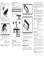
1
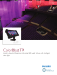
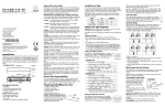
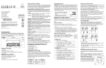
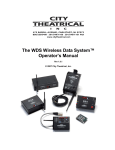
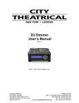
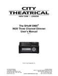
Identification and Warnings of Safety Hazards
In accordance with ANSI Z535.4-2002 the following system of
identifying the severity of the hazards associated with the products
is used:
c olorrbla s t 1 2 t r
u s e r
g u i d e
Color Kinetics Incorporated
10 Milk street, Suite 1100
Boston, MA 02108 USA
Tel 888 Full RGB
Tel 617 423 9999
Fax 617 423 9998
[email protected]
www.colorkinetics.com
DRY
ITEM# 116-000019-00
This product is protected by one or more of the following patents: U.S. Patent Nos.
6,016,038, 6,150,774 and other patents listed at http://colorkinetics.com/patents/.
Other patents pending.
©2006 Color Kinetics Incorporated. All rights reserved. Chromacore, Chromasic,
CK, the CK logo, Color Kinetics, the Color Kinetics logo, Color Kinetics The Leader
in Intelligent Light, ColorBlast, ColorBlaze, ColorBurst, ColorCast, ColorPlay,
ColorScape, DIMand, Direct Light, EssentialWhite, eW, iColor, iColor Cove,
IntelliWhite, iW, iPlayer, Light Without Limits, Optibin, Powercore, QuickPlay, Sauce,
the Sauce logo, and Smartjuice are either registered trademarks or trademarks of
Color Kinetics Incorporated in the United States and/or other countries.
All other brand or product names are trademarks or registered trademarks of their
respective owners.
PUB-000173-00 Rev.00
Specifications subject to change without notice. Refer to www.colorkinetics.com for
the most recent version.
Introduction
Color Kinetics® ColorBlast® 12 TR offers wall-washing, wall-grazing, and spot lighting in an easy-to-install fixture. This user guide
contains important information about proper installation and safe
operation of your new ColorBlast 12 TR light fixture.
Included in This Box
•C
olorBlast 12 TR and preassembled base with 6-ft (1.83m) 3C
18AWG SJTW Cable and a 4-pin XLR connector
•1
Clear, Tempered Glass Lens
• 1 Frosted, Tempered Glass Lens
• 1 Protective Cover
• 3/16" Hex Key
• User Guide
Additional Items Needed
•2
4VDC power/data supply—PDS-750TR (Item# 109-000019-00)
• Controller—Color Kinetics or DMX compatible
Optional Items
•3
/16" OD braided safety cable and hardware, as required.
Scope of This User Guide
The goal of this user guide is to explain the steps needed to install
the ColorBlast 12 TR fixture, and assure peak performance. Its
intended use is for reference only, by persons who are fully qualified. This document should never be considered a substitute for any
provisions of a regulation or any applicable state or local code.
“danger” Imminently hazardous situation which, if not avoided,
will result in death or serious injury.
“warning” Potentially hazardous situation which, if not avoided,
could result in death or serious injury.
“caution” Potentially hazardous situation which, if not avoided,
may result in minor or moderate injury or property damage. Also used to alert against unsafe practices.
ignoring a hazard will void any warranty.
danger: Ensure that the main power supply is off before installing
or wiring the ColorBlast 12 TR and power/data supply.
warning: The ColorBlast 12 TR and power/data supply must be
installed by a qualified professional in accordance with NEC and
relevant local codes.
warning: Do not attempt to install or use the ColorBlast 12 TR or
power/data supply until you read and understand the installation
instructions and safety labels.
caution: The ColorBlast 12 TR has no serviceable electronic parts.
Do not attempt to service the fixture.
caution: Do not modify, alter, or attempt to service the
ColorBlast 12 TR.
caution: You must use the cable provided with the unit.
caution: Do not use sharp tools near or on the fixture lens.
caution: Do not hot swap. Ensure the power supply is off before
connecting or disconnecting fixtures.
caution: Do not overload the power/data supply.
note: The instructions and precautions set forth in this installation
guide are not necessarily all-inclusive, all-conceivable, or relevant to
all applications as Color Kinetics cannot anticipate all conceivable
or unique situations.
Owner/User Responsibilities
It is the responsibility of the contractor, installer, purchaser, owner
and user to install, maintain, and operate the ColorBlast 12 TR in
such a manner as to comply with all state and local laws, ordinances, regulations, and the American National Standard Institute
(ANSI) Safety Code.
Planning the Installation
The ColorBlast 12 TR installation requires planning to ensure a timely, successful installation with minimal complications and down time.
Planning Suggestions
When planning a ColorBlast 12 TR installation, Color Kinetics suggests doing the following:
•Consult an Electrical Inspector to review all wiring plans, where
needed.
• Refer to local and state codes for installation compliance.
• Create a Layout Plan drawing.
• Create a Mapping Grid. Use this grid to record serial numbers
for easy reference and addressing.
• Consult Color Kinetics Application Engineering Services as needed at www.colorkinetics.com/support.
• Get detailed wiring diagrams and additional support from www.
colorkinetics.com/support.
Installation Considerations
• L ocation of the power/data supplies in relationship to
lights. Each ColorBlast 12 TR comes with a 6-ft (1.83m) power/
data cable. The power/data supply must be located within 60
feet (18.3m) of the ColorBlast 12 TR fixtures.
• Location of the fixture and method of mounting. The
ColorBlast 12 TR can be installed on a pipe, truss, or floor.
Mounting methods vary according to location.
Installing Power/Data Supplies
The ColorBlast 12 TR can be operated in one of three modes:
• CB
• Pass Thru
• Stand-Alone
Consult the PDS-750TR User Manual from City Theatrical, Inc.
(www.citytheatrical.com) for more information on the operating
modes.
CB Mode
In CB mode, the system will route DMX (as Color Kinetics data protocol) to each output based on the selected DMX starting address.
Each fixture is set as CK Light 1 (DMX 001, 002, 003). The PDS750TR's internal DMX Manager selectively routes DMX data to each
light output so that each light receives only the data packets that it is
supposed to respond to. The effective DMX address of each fixture
is a function of the starting address of the PDS-750TR, combined
with the number of the output that the fixture is connected to.
With the DMX Address set to 001:
Fixture 1 = DMX 1, 2, & 3
Fixture 2 = DMX 4, 5 & 6,
etc.
To put the fixture into CB mode, set the DMX Address switches to a
desired address other than 000. The fixture can be set to any valid
DMX address, however, please note that any starting address over
476 will disable some outputs.
Configuration/System Setup for CB Mode (DMX
Managed)
To configure the fixture to CB Mode:
1. Using the onboard Mini-Zapi on the PDS-750TR (see City
Theatrical PDS-750TR User Guide) or the Color Kinetics Zapi™
(see the Zapi User Guide), pre-address all ColorBlast 12 TR fixtures as DMX 001.
2. P
lug up to 12 of those ColorBlast 12 TR fixtures into outputs 1-12
(one per output).
3. Connect the PDS to a DMX source, via the DMX In port and connect power.
4.Set the PDS DMX address to the desired starting address value
AAA.
5.The 12 connected ColorBlast 12 TR fixtures will respond as follows:
Fixture #1 = DMX address AAA, AAA+1, AAA+2
Fixture #2 = DMX address AAA+3, AAA+4, AAA+5
Fixture #3 = DMX address AAA+6, AAA+7, AAA+8
etc.
Pass Thru Mode
In Pass Thru mode, the system will convert all the DMX values to
Color Kinetics data protocol, and send that CK data (with 24V
power) to all 12 ColorBlast 12 TR outputs. The Pass Thru mode is
used for ColorBlast 12 TR fixtures powered by the PDS-750TR in
a system requiring Zapi addressing schemes, such as when being
used in combination with other Color Kinetics power supplies like
the PDS-150.
Pass Thru mode is selected whenever the DMX Address switches
are set to all zeros (000) and the Config switch is set to 0.
Stand Alone Effects Mode
In Stand Alone mode the PDS-750TR will run various
preprogrammed effects without a console. This is very useful for
events like parties or trade shows, where a constantly running
program is desired without the use of a console or show programming.
The unit is placed into Stand Alone mode using the Config BCD
switch. When the unit is in Stand Alone mode, the DMX Address
switches become Effects controls. Different Stand Alone Effects are
selected via different setting combinations of the DMX Address
switches and the Config switch.
Installing the Fixtures
danger:
Ensure that main power supply is off before installing or
wiring the ColorBlast 12 TR and power data supply. Failure to
adhere to these instructions will result in death or serious injury,
and will void the warranty.
warning:
The ColorBlast 12 TR and the power/data supply must
be installed by a qualified professional in accordance with NEC
and relevant local codes. Failure to comply could result in death
or serious injury, and will void the warranty.
Connecting ColorBlast 12 TR Fixtures to the
PDS-750TR
The PDS-750TR is provided with a female 4-pin XLR connectors for
output connections to the ColorBlast 12 TR fixtures. The connector
pinout is as follows:
PIN #
Signal
CK Cable Wire Color
1
+24 VDC
Red
2
(n/c)
3
Data
White
4
DC Common
Black
Color Kinetics ColorBlast 12 TR fixtures are provided with a permanently connected 6-ft (1.83m) cable. The maximum distance
between the PDS-750TR and the ColorBlast 12 TR can be 60 ft
(18.3m).
Pipe/Truss Mount
The ColorBlast 12 TR can be mounted to a pipe or truss using a
standard theatrical C-clamp. The ColorBlast 12 TR is provided with
a clearance hole for a 1/2" bolt on the mounting base for attaching
C-clamps. When mounting the ColorBlast 12 TR in this way, all necessary care should be taken to ensure that the installation is suitable
and safe and that the hardware is properly rated for the task. (See
Fig. 1.)
Fig. 1
Floor Mount
When mounting the ColorBlast 12 TR on the floor, ensure that the
fixture sits flush to the surface and use mounting hardware suitable
for the mounting surface. (See Fig. 2.)
Fig. 2
Making Electrical Connections
ColorBlast 12 TR is compatible with Color Kinetics PDS-750TR
power/data supplies.
To change lenses:
1. Remove the protective cover from the fixture. (See Fig. 5.)
Fig. 5
Connecting Power
ColorBlast 12 TR requires 24VDC. After installing the light fixtures,
connect the power/data cable to the power/data supply. The PDS750TR supports 12 ColorBlast 12 TR fixtures.
caution:
Aim fixture and
lock in place.
Do not overload the power/data supply. Doing so may
result in minor or moderate injury or property damage and will
void the warranty.
FRONT VIEW
note:
Each light must receive power directly from a power/data
supply. You cannot daisy chain power from one ColorBlast 12 TR
to another. The ColorBlast 12 TR cable contains three color-coded
wires through a 4-pin XLR connector. (See Fig. 4.)
•B
lack = GND
•W
hite = Data
• Red = +24 VDC
Attaching the Safety Cable
Each fixture is designed for use with a safety cable. When required
by local or state code, or by a Structural Engineer, attach a safety
cable from the fixture to the mounting surface.
1. Locate the safety cable bracket on rear of the ColorBlast 12 TR.
(See Fig. 3.)
Protective Cover
2. T here are two lock-down screws located on the fixture sides, one
per side at the top of the bezel. Remove these two screws. (See
Fig. 6.)
Fig. 6
Lock-down Screws
If strobe lights are used, some international regulatory agencies¹
recommend keeping flicker rates at or below four flashes per second (as less of the flicker-sensitive population will then be at risk of
an attack). This flicker rate applies only to the overall output of any
group of lights in direct view. However, when more than one strobe
light is used, the flashes should be synchronized. End users should
also consider issuing a warning, alerting audience or viewers to the
presence of strobe lighting.
Temperature Monitoring
For protection from extreme temperatures, ColorBlast 12 TR has
been designed with a temperature monitoring feature. If operating
temperatures rise to an unsafe level, a compensation circuit is triggered and the ColorBlast 12 TR operation is interrupted, causing
the lights to turn dull red. After 30 minutes the lights will auto-cycle.
To prevent additional power shut-downs, determine the cause of the
overheating and correct the problem.
If any problems occur during usage, unplug the product immediately
and call Color Kinetics Technical Support Group: 1-888-FULL RGB
or 617-423-9999 or email us: [email protected].
ColorBlast 12 TR specifications
16.7 million (24-bit) additive RGB colors;
continuously variable intensity output range
source High intensity power light emitting diodes (LEDs)
beam angle 23º beam angle (frosted), 10º (clear)
housing Die Cast Aluminum, black
protective cover TPV Elastomer, black
lens Soft-focus tempered glass or clear tempered glass
connectors 6-foot (1.83cm) Unified power and data cable with
4-pin XLR connector
listings UL/cUL, CE
color range
Fig. 4
Fig. 3
CARABINER
CLIP
communication Specifications
Lens
data interface
control
END USER SPECIFIES
REQUIRED END TERMINATOR
AND ANCHORING
2. Attach the safety cable to the mounting surface. Consult a
Structural Engineer and refer to applicable standards for your
specific application to determine the proper method for mounting
the safety cable to the installation surface.
Safety cables used in the installation must meet the following
minimal requirements:
material: 316 Stainless Steel
size: 5/64-inch (0.78-inch nominal diameter) or
larger, minimum break load must be greater than 400 pounds. Maximum diameter is 3/16-inch.
construction: 7 x 7 (49 wires) preformed stranded
end terminations:
Determined by installer and/or owner
mounting method: Determined by installer or owner
Bezel
PDS-750TR
110-240VAC
DMX In
Color Kinetics
Controller or DMX512
Compatible controller
DMX Out
(for multiple
power/data
supplies)
LENS REPLACEMENT
The ColorBlast 12 TR is designed to allow the user to change
between two lens options - clear and frosted. Both lenses are included with the fixture.
The clear lens option features a 10º beam angle and is designed
for long throw, spot lighting applications. The frosted lens option
provides a 23º beam angle and is designed for wash lighting applications.
note:
The bezel pivots at the edge closets to the base. It is not
necessary to remove the pivot screws.
3. Using the tabs on the bezel, pivot the bezel forward to access
the lens. (See Fig. 6).
4.Remove the installed lens and replace it with the desired lens.
Make sure the gasket around the lens is properly fitted.
5.Close the bezel, install the lock-down screws, and replace the
protective cover.
ROUTINE MAINTENANCE
Cleaning: Use a soft cloth. Clean surface with mild soap and
water or window cleaner.
Lubrication: As needed, apply light household oil to the hinges.
IMPORTANT INFORMATION
Strobe Warning
There is anecdotal evidence which suggests that strobe lighting
may induce epileptic symptoms in certain susceptible individuals, although no associated product warnings have been issued
by the United States government according to the Food and Drug
Administration.
Color Kinetics data interface system
Color Kinetics controllers or other DMX512 (RS485)
compatible if using Color Kinetics power/data supply
electrical Specifications
power requirement
power consumption
power supply
24VDC
50W Max. at full intensity (full RGB)
PDS-750TR (ITEM# 109-000019-00)
Environmental Specifications
temperature range
-40ºF to 122ºF (-40ºC to 50ºC) operating temperature
-4ºF to 122ºF (-20ºC to 50ºC) starting temperature
LED Source Life
In traditional lamp sources, lifetime is defined as the point at which 50% of the lamps fail. This is also
termed Mean Time Between Failure [MTBF]. LEDs are semiconductor devices and have a much longer
MTBF than conventional sources. However, MTBF is not the only consideration in determining useful
life. Color Kinetics uses the concept of useful light output for rating source lifetimes. Like traditional
sources, LED output degrades over time (lumen depreciation) and this is the metric for SSL lifetime.
LED lumen depreciation is affected by numerous environmental conditions such as ambient temperature, humidity, and ventilation. Lumen depreciation is also affected by means of control, thermal
management, current levels, and a host of other electrical design considerations. Color Kinetics
systems are expertly engineered to optimize LED life when used under normal operating conditions.
Lumen depreciation information is based on LED manufacturers’ source life data as well as other third
party testing. Low temperatures and controlled effects have a beneficial effect on lumen depreciation.
Overall system lifetime could vary substantially based on usage and the environment in which the
system is installed.
Temperature and effects will affect lifetime. Color Kinetics rates product lifetime using lumen depreciation to 50% of original light output. When the fixture is running at room temperature using a color
wash effect, the lifetime is in the range of 80,000-100,000 hours. This is based on LED manufacturers’ test data. High output is defined as any LED device that is 1/2 watt or above. For more detailed
information on source life, please see www.colorkinetics.com/lifetime.
Warranty
This product is sold pursuant to CK’s Standard Terms and Conditions (the “T&Cs”) which may be
found at http://colorkinetics.com/howtobuy/buy/terms and which contain important provisions,
including, among others, Limited Warranty, exclusions and limitations on CK’s liability for damages,
and restrictions on the remedies that are available to you.
1.
Guide to Health, Safety and Welfare at Pop Concerts and Similar Events, HMSO Publications (UK)