1
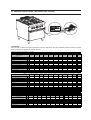
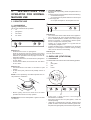
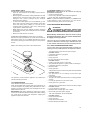
CONTENTS
I. JOINING APPLIANCES / TABLES .................................................................................................... 2
II. DATAPLATE and TECHNICAL DATA ................................................................................................ 23
III. FOREWORD ...................................................................................................................................... 24
IV. INSTALLATION .................................................................................................................................. 25
1. GENERAL INFORMATION ................................................................................................................. 25
2. TRANSPORT, HANDLING AND STORAGE ....................................................................................... 27
3. INSTALLATION AND ASSEMBLY ....................................................................................................... 28
4. FUME EXHAUST ............................................................................................................................... 29
5. CONNECTIONS ................................................................................................................................. 29
6. SAFETY THERMOSTAT ..................................................................................................................... 31
7. BEFORE COMPLETING INSTALLATION OPERATIONS ................................................................... 31
8. HANDRAIL ......................................................................................................................................... 32
V. INSTRUCTIONS FOR OPERATOR FOR NORMAL MACHINE USE ................................................ 32
1. COOKTOP ......................................................................................................................................... 32
2. OVEN USE (STATIC/FAN) .................................................................................................................. 32
VI. CLEANING AND MAINTENANCE .................................................................................................... 34
1. GENERAL SAFETY RULES ............................................................................................................... 34
2. NORMAL MACHINE USE .................................................................................................................. 35
3. MACHINE CLEANING AND MAINTENANCE .................................................................................... 36
4. MACHINE DISPOSAL ........................................................................................................................ 38
5. MAINTENANCE ................................................................................................................................. 39
22
II. DATAPLATE and TECHNICAL DATA
ATTENTION
This manual contains instructions relevant to various appliances. See the dataplate located under the control
panel to identify the appliance (see fig. above).
TABLE A - Gas/electrical ap pliance techn ical d ata
MO DELS
+9GCGD2C00
400m m
TECHNICAL DATA
+9GCGD2C0M +9GCGT 2C0M +9GCGH4C00 +9GCGH4C0M
400m m
400m m
800m m
800m m
+9GCT H4C00
800m m
+9GCTH4C0M
800m m
+9GCGL 6C00
1200m m
+9GCGL6C0M +9GCT L6C0M +9GCGH4C GL
1200m m
1200m m
800m m
V
-
-
-
-
-
-
-
-
-
-
-
Ele ctr ic al pow er a bs orbed
kW
-
-
-
-
-
-
-
-
-
-
-
Pha ses
No.
-
-
-
-
-
-
-
-
-
-
-
Frequency
Hz
-
-
-
-
-
-
-
-
-
-
-
Connec tion ISO 7 /1 - BS/P conne ction(*)
Ø
1/2"
1/2"
1/2"
1/2"
1/2"
1/2"
1/2"
1/2"
1/2"
1/2"
1/2"
Pow er supply voltage
Cooktop burners
No.
2
2
2
4
4
4
4
6
6
6
4
Cooktop nom ina l heat output
kW
12
20
15
28
40
24
30
44
60
45
24
A1
A1
A1
A1
A1
A1
A1
A1
A1
A1
A1
-
-
-
-
-
-
-
-
-
-
-
Gas
Ove n m ax . hea t output
kW
-
-
-
-
-
-
-
-
-
-
8,5
Ove n m in. he at output
kW
-
-
-
-
-
-
-
-
-
-
-
Nom ina l hea t output
kW
12
20
15
28
40
24
30
44
60
45
32,5
Type of c onstruction
Ove n type
(*)=AUS TRALIA
MO DELS
+9GCGH4C GM
800m m
TECHNICAL DATA
Pow er supply voltage
+9GCGL6C10 +9GCGL 6C1M +9GCGP8CG0 +9GCGL6CL0
1200m m
1200m m
1600m m
1200m m
+9GCGL 6CLM
1200m m
+9GCGH4CV L +9G CGH4CV 0 +9GCGH4CV M
+9GCT H4CEM +9GCGH4CE0
+9GCGH4SV L +9GCGH4SV 0 +9GCGH4SV M
800m m
800m m
800m m
800m m
800m m
V
-
-
-
-
-
-
230
230
230
400
Ele ctr ic al pow er a bs orbed
kW
-
-
-
-
-
-
0,25
0,25
0,25
6
6
Pha ses
No.
-
-
-
-
-
-
1
1
1
3N
3N
Frequency
Hz
-
-
-
-
-
-
50
50
50
50/60
50/60
Connec tion ISO 7 /1 - BS/P conne ction(*)
Ø
1/2"
1/2"
1/2"
1/2"
1/2"
1/2"
1/2"
1/2"
1/2"
1/2"
1/2"
Cooktop burners
No.
4
6
6
8
6
6
4
4
4
4
4
Cooktop nom ina l heat output
kW
40
44
60
56
44
60
24
28
40
24
28
A1
A1
A1
A1
A1
A1
A1
A1
A1
A1
A1
-
Gas
Gas
Gas
Gas
Gas
Gas
Gas
Gas
Gas
Ele ctr ic
Ele ctr ic
Ove n m ax . hea t output
kW
8,5
8,5
8,5
17
12
12
10,5
10,5
10,5
-
-
Ove n m in. he at output
kW
-
-
-
-
-
-
-
-
-
-
-
Nom ina l hea t output
kW
48,5
52,5
68,5
73
56
72
34,5
38,5
50,5
24
28
Type of c onstruction
Ove n type
400
(*)= AUS TRALIA
T AB LE A - E le ctrical ap plianc e techn ical d ata
M O DEL S
TECHNICAL DATA
+9 ECED2Q0 0
40 0m m
+9ECED2 Q0 N
40 0m m
+9 EC M D20 05
40 0m m
+9ECM D200 6
4 00m m
+9ECEH4 Q00
800 m m
+9EC EH4Q0N
800 m m
+9ECM H400 5
800 m m
+9EC M H40 06
80 0m m
+9 EC EH4QE0
8 00m m
+9 EC EH4QEN
8 00m m
+9EC M H4 025
8 00m m
+9 ECM H402 6
800 m m
4 40
V
380 -40 0
23 0
400
44 0
3 80-4 00
230
40 0
440
38 0-40 0
2 30
400
Pha s e s
No.
3N
3
3
3
3N
3
3
3
3N
3
3
3
Fre quenc y
Hz
5 0/60
50 /6 0
5 0/60
50/60
50 /6 0
50/60
50 /6 0
5 0/60
50/60
50 /60
50/60
50 /6 0
Cook top hot-pla te s
No.
2
2
2
2
4
4
4
4
4
4
4
4
Cook top hot-pla te m a x . pow e r
kW
5,2
5 ,2
5,2
5,2
10,4
10 ,4
10,4
10 ,4
1 0,4
10 ,4
1 0,4
10,4
Ove n m a x. pow e r
kW
-
-
-
-
-
-
-
-
6
6
6
6
Nom ina l m a x . pow er
kW
4.5 - 5.2
4.5 - 5.2
4.5- 5.2
4 .5 -5.2
9 - 1 0.4
9 - 10.4
9 - 10 .4
9 - 1 0.4
14.6 - 16.4
14 .6 - 16 .4
1 4.6 - 16.4
14.6 - 16 .4
Pow e r c a ble s e c tion
mm2
4
4
4
4
4
4
4
4
4
4
4
4
Pow e r s upply volta ge
23
III. FOREWORD
The installation, use and maintenance Manual (hereinafter Manual) provides the user with information
necessary for correct and safe use of the machine (hereinafter “machine” or “appliance”). The following
must not be considered a long and exacting list of warnings, but rather a set of instructions suitable
for improving machine performance in every respect and, above all, preventing injury to persons and
animals and damage to property due to improper operating procedures. All persons involved in
machine transport, installation, commissioning, use and maintenance, repair and disassembly must consult
and carefully read this manual before carrying out the various operations, in order to avoid wrong and improper
actions that could compromise the machine’s integrity or endanger persons. Make sure to periodically inform
the appliance user regarding the safety regulations. It is also important to instruct and update personnel authorised
to operate on the machine, regarding its use and maintenance. The manual must be available to operators and
carefully kept in the place where the machine is used, so that it is always at hand for consultation in case of
doubts or whenever required. If, after reading this manual, there are still doubts regarding machine use, do not
hesitate to contact the Manufacturer or the authorised after-sales service centre, to receive prompt and precise
assistance for better operation and maximum efficiency of the machine. During all stages of machine use,
always respect the current regulations on safety, work hygiene and environmental protection. It is the user’s
responsibility to make sure the machine is started and operated only in optimum conditions of safety for persons,
animals and property.
The manufacturer declines any liability for operations carried out on the appliance without respecting
the instructions given in this manual. No part of this manual may be reproduced.
24
IV. INSTALLATION
1. GENERAL INFORMATION
•
AUSTRALIA: this appliance shall be installed only by
authorised persons and in accordance with the
manufacturer’s installation instructions, local gas fitting
regulations,municipal building codes, electrical wiring
regulations, local water supply regulations, AS5601-gas
installation, health authorites and any other statutory
regulations.
1.1 INTRODUCTION
Given below is some basic information regarding the
machine’s intended use, its testing, and a description of
the symbols used (that identify the type of warning), the
definitions of ter ms used in the manual and useful
information for the appliance user.
1.2 INTENDED USE AND RESTRICTIONS
Install the appliance in compliance with the current
regulations and laws regarding installation of electric
and gas appliances.
Our appliances are designed and optimised in order to
obtain high performance and efficiency. This appliance is
designed for cooking food. Any other use is deemed
improper. The appliance is not intended for use by people
(including children) with limited physical, sensory or mental
abilities or without experience and knowledge of it, unless
they are supervised or instructed in its use by a person
responsible for their safety.
ATTENTION: The machine is not suitable for installation
outdoors and/or in places exposed to atmospheric agents
(rain, direct sunlight, etc.).
The manufacturer declines any liability for improper use
of the product.
1.3 TESTING AND INSPECTION
Our appliances are designed and optimised, with laboratory
testing, in order to obtain high performance and efficiency.
The product is shipped ready for use. Passing of the tests
(visual inspection - electrical/gas test - functional test) is
guaranteed and certified by the specific enclosures.
1.4 DEFINITIONS
Listed below are the definitions of the main terms used in
the manual. Carefully read them before using the manual.
Operator
machine installation, adjustment, use, maintenance,
cleaning, repair and transport personnel.
Manufacturer
Electrolux Professional SPA or any other service centre
authorised by Electrolux Professional SPA.
Operator for normal machine use
an operator who has been informed and trained regarding
the tasks and hazards involved in normal machine use.
Technical assistance or specialised technician
an operator instructed/trained by the Manufacturer and who,
based on his professional and specific training, experience
and knowledge of the accident-prevention regulations, is
able to appraise the operations to be carried out on the
machine and recognise and prevent any risks. His
professionalism covers the mechanical, electrotechnical and
electronics fields.
Danger
source of possible injury or harm to health.
Hazardous situation
any situation where an operator is exposed to one or more
hazards.
Risk
a combination of probabilities and risks of injury or harm to
health in a hazardous situation.
Protection devices
safety measures consisting of the use of specific technical
means (guards and safety devices) for protecting operators
against risks.
Guard
an element of a machine used in a specific way to provide
protection by means of a physical barrier.
Safety device
a device (other than a guard) that eliminates or reduces the
risk; it can be used alone or in combination with a guard.
Customer
the person who purchased the machine and/or who
manages and uses it (e.g. company, entrepreneur, firm).
Electrocution
an accidental discharge of electric current on a human body.
1.5 TYPOGRAPHICAL CONVENTIONS
For best use of the manual, and therefore the machine, it is
advisable to have good knowledge of the terms and
typographical conventions used in the documentation. The
following symbols are used in the manual to indicate and
identify the various types of hazards:
ATTENTION!
RISK FOR THE HEALTH AND SAFETY
OF OPERATORS.
ATTENTION!
DANGER OF ELECTROCUTION DANGEROUS VOLTAGE.
ATTENTION!
RISK OF DAMAGE TO THE MACHINE.
Words further explaining the type of hazard are placed next to
the symbols in the text. The warnings are intended to guarantee
the safety of personnel and prevent damage to the machine
or the product being worked. The drawings and diagrams given
in the manual are not in scale. They supplement the written
information with an outline, but are not intended to be a detailed
representation of the machine supplied. The numerical values
given on the machine installation diagrams refer to
measurements expressed in mm.
25
1.6 MACHINE AND MANUFACTURER’S IDENTIFICATION
DATA
A reproduction of the marking or dataplate on the machine
is given below:
ATTENTION!
Do not remove, tamper with or make the
machine “CE” marking illegible.
ATTENTION!
Refer to the data given on the machine “CE”
marking for relations with the Manufacturer
(e.g. when ordering spare parts, etc.).
GAS
AB
N
ATTENTION!
When scrapping the machine, the “CE”
marking must be destroyed.
1.7 APPLIANCE IDENTIFICATION
This manual contains instructions relevant to various
appliances.
See the appliance dataplate located under the control panel
to identify the appliance product code.
1.8 COPYRIGHT
This manual is intended solely for consultation by the
operator and can only be given to third parties with the
permission of Electrolux Professional SPA.
EL.
AB
N
The meaning of the various information given on it is listed
below:
F.Mod. .................................... factory description of product
Comm.Model ......................... commercial description
PNC ....................................... production number code
Ser.No .................................... serial number
El: ........................................... power supply voltage+phase
Hz: ......................................... power supply frequency
kW: ......................................... max. power input
A ............................................. current absorption
Power unit El.: ....................... power
I .............................................. dust and water protection rating
CE .......................................... CE marking
AB .......................................... gas safety certificate number
N ............................................ certification group
0051 ....................................... notified body
EN 203-1 ............................... EU standard
L ............................................. Logo INQ/GS
Cat ......................................... Gas Category
Pmbar .................................... Gas pressure
Electrolux Professional SPA
Viale Treviso, 15
33170 Pordenone
(Italy) Manufacturer
When installing the appliance, make sure the electrical
connection is carried out in compliance with that specified
on the dataplate.
26
1.9 RESPONSIBILITY
The Manufacturer declines any liability for damage and
malfunctioning caused by:
• non-compliance with the instructions contained in this
manual;
• repairs not carried out in a workmanlike fashion, and
replacements with parts different from those specified in
the spare parts catalogue (the fitting and use of non-original
spare parts and accessories can negatively affect machine
operation and invalidates the warranty);
• operations by non-specialised technicians;
• unauthorised modifications or operations;
• inadequate maintenance;
• improper machine use;
• unforeseeable extraordinary events;
• use of the machine by uninformed and untrained personnel;
• non-application of the current provisions in the country of
use, concerning safety, hygiene and health in the workplace.
The Manufacturer declines any liability for damage caused
by arbitrary modifications and conversions carried out by
the user or the Customer. The employer, workplace manager
or service technician are responsible for identifying and
choosing adequate and suitable personal protection
equipment to be worn by operators, in compliance with
regulations in force in the country of use.
Electrolux Professional SPA declines any liability for any
inaccuracies contained in the manual, if due to printing or
translation errors.
Any supplements to the installation, use and maintenance
manual the Customer receives from the Manufacturer will
form an integral part of the manual and therefore must be
kept together with it.
1.10 PERSONAL PROTECTION EQUIPMENT
Given below is a summary table of the Personal Protection
Equipment (PPE) to be used during the various stages of
the machine’s service life.
Stage
e
tiv s
ec nt
ot me
r
P ar
g
ty ar
fe e
Sa otw
fo
s
ve
lo
G
es
ss
la
G
ty
fe
Sa
et
lm
he
Transport
The machine must only be transported, handled and stored
by qualified personnel, who must:
- have specific technical training and experience in the use
of lifting systems;
- have knowledge of the safety regulations and applicable
laws in the relevant sector;
- have knowledge of the general safety rules;
- ensure the use of personal protection equipment suitable
for the type of operation carried out;
- be able to recognise and avoid any possible hazard.
Handling
2.2 TRANSPORT: INSTRUCTIONS FOR THE CARRIER
Unpacking
Assembly
ATTENTION!
Do not stand under suspended loads during
loading/unloading operations. Unauthorised
personnel must not enter the work area.
Normal use
Adjustments
Routine
cleaning
Extraordinary
cleaning
Maintenence
Dismantling
Scrapping
Key:
PPE REQUIRED
PPE AVAILABLE OR TO BE USED IF NECESSARY
PPE NOT REQUIRED
During Normal use , gloves protect hands from contact with
hot food or hot parts of the appliance.
1.11 KEEPING THE MANUAL
The manual must be carefully kept for the entire life of the
machine, until scrapping.
The manual must stay with the machine in case of transfer,
sale, hire, granting of use or leasing.
1.12 RECIPIENTS OF THE MANUAL
This manual is intended for:
• the carrier and handling personnel;
• installation and commissioning personnel;
• the employer of machine users and the workplace
manager;
• operators for normal machine use;
• specialised technicians - after-sales service.
2. TRANSPORT, HANDLING AND
STORAGE
2.1 INTRODUCTION
Transport (i.e. transfer of the machine from one place to
another) and handling (i.e. transfer inside workplaces) must
occur with the use of special and adequate means.
ATTENTION!
Given their size, the machines can be stacked
on top of each other during transport, handling
and storage by complying with that specified
on the slip placed on the packing;
ATTENTION!
The machine’s weight alone is not sufficient
to keep it steady. The transported load can
shift:
- when braking;
- when accelerating;
- in corners;
- on rough roads.
2.3 HANDLING
Arrange a suitable area with flat floor for machine unloading
and storage operations.
2.4 PROCEDURES FOR HANDLING OPERATIONS
For correct and safe lifting operations:
• use the type of equipment most suitable for characteristics
and capacity (e.g. electric pallet truck or lift truck);
• cover sharp edges;
Before lifting:
• send all operators to a safe position and prevent persons
from entering the handling area;
• make sure the load is stable;
• make sure no material can fall during lifting. Manoeuvre
vertically in order to avoid impacts;
• handle the machine, keeping it at minimum height from
the ground.
ATTENTION!
For machine lifting, do not use movable or weak
parts such as: casings, electrical raceways,
pneumatic parts, etc.
2.5 TRANSLATION
The operator must:
• have a general view of the path to be followed;
• stop the manoeuvre in case of hazardous situations.
ATTENTION!
Do not push or pull the appliance to move it,
as it may tip over.
27
2.6 PLACING THE LOAD
Before placing the load, make sure the way is free and that
the floor is flat and can take the load. Remove the appliance
from the wooden pallet, move it to one side, then slide it onto
the floor.
2.7 STORAGE
The machine and/or its parts must be stored and protected against
damp, in a non-aggressive place free of vibrations and with room
temperature between -10°C and 50°C. The place where the
machine is stored must have a flat support surface in order to
avoid any twisting of the machine or damage to the support feet.
ATTENTION!
Machine positioning, installation and
disassembly must be carried out by a
specialised technician.
ATTENTION!
Do not make modifications to the par ts
supplied with the machine. Any missing or
faulty parts must be replaced with original
parts.
Warnings
• Do not store or use gasoline or other flammable vapours,
liquids or items in the vicinity of this or any other
appliance.
• Do not spray aerosols in the vicinity of this appliance
while it is in operation.
•
Never check for leaks with an open flame.
• The appliance is not suitable for a marine environment.
3. INSTALLATION AND ASSEMBLY
To ensure correct operation of the appliance and maintain
safe conditions during use, carefully follow the instructions
given below in this section.
ATTENTION!
The operations described below must be
carried out in compliance with the current
safety regulations, regarding the equipment
used and the operating procedures.
ATTENTION!
Before moving the appliance make sure the
capacity of the lifting equipment used is
suitable for its weight.
3.1 CUSTOMER’S RESPONSIBILITIES
The Customer must:
- prearrange a high-sensitivity manual-reset differential
thermal-magnetic switch. For information regarding the
electrical connection, refer to par. 5.2 “Electrical connection”;
- check the flatness of the surface on which the machine is placed.
- prearrange a device lockable in the open position for the
connection to the power supply.
- prearrange the connection to a suitable earthing system
(par. 5.2.3)
- install a rapid gas shutoff cock/valve ahead of each individual
appliance. Install the cock/valve in an easily accessed place.
28
3.2 MACHINE SPACE LIMITS
A suitable space must be left around the machine (for
operations, maintenance, etc.). This space must be
increased in case of use and/or transfer of other equipment
and/or means or if exit routes are necessary inside the
workplace.
RISK OF FIRE - Keep the area around the
appliance free and clear of combustibles.
Do not keep flammable materials in the vicinity
of this appliance.
Install the appliance in a well-ventilated place to avoid the
creation of dangerous mixtures of unburnt gases in the same
room.
Air recirculation must take into account the air necessary for
combustion 2 m³/h/kW of gas power, as well as the well-being
of persons working in the kitchen.
Inadequate ventilation causes asphyxia. Do not obstruct
the ventilation system in the place where this appliance
is installed.
Do not obstruct the vents or ducts of this or other
appliances.
Place emergency telephone numbers in a visible
position.
3.3 POSITIONING
The installation diagram provided in this instruction manual
gives the appliance overall dimensions and the position of
connections (gas, electricity, water).
The appliance can be installed separately or combined with
other appliances of the same range.
The appliances are not suitable for recess-mounting. Leave at
least 10 cm between the appliance and side or rear walls.
Suitably insulate surfaces that are at distances less than
that indicated. Maintain an adequate distance between the
appliance and any combustible walls. Do not store or use
flammable materials and liquids near the appliance.
Install the appliance, taking all the safety precautions required
for this type of operation, also respecting the relevant fireprevention instructions. If the machine is installed in places
where there are corrosive substances (chlorine, etc.), it is
advisable to go over all the stainless steel surfaces with a
rag soaked in paraffin oil to create a protective film. The
machine must be taken to the place of installation and the
packing base removed only when being installed.
Arranging the machine:
• position the machine in the required place;
• adjust the height and levelling with the adjustment feet,
also checking correct door closing
NOTE
PERMANENT CONNECTION: the device lockable
in the open position must be accessible even after
the appliance is installed in its place.
• wear protective gloves and unpack the machine, carrying
out the following operations:
- cut the straps and remove the protective film, taking care
not to scratch the surface if scissors or blades are used;
- remove the polystyrene corners and the vertical protection
pieces. For appliances with stainless steel cabinet, remove the
protective film very slowly without tearing it, to avoid leaving
glue stuck to the surface. Should this happen, remove the traces
of glue with a non-corrosive solvent, rinsing it off and drying
thoroughly; it is advisable to go over all the stainless steel
surfaces with a rag soaked in paraffin oil in order to create a
protective film.
3.4 DISPOSAL OF PACKING
The packing must be disposed of in compliance with the current
regulations in the country where the appliance is used. All the
packing materials are environmentally friendly. They can be safely
kept, recycled or burnt in an appropriate waste incineration plant.
Recyclable plastic parts are marked as follows:
PE
4.2. TYPE “B” APPLIANCES
(in conformity with the definition given in the Installation
Technical Regulations DIN-DVGW G634: 1998)
Whenever the appliance dataplate specifies only type Axx,
such appliances are not designed for being directly connected
to a flue or fume exhaust pipe run to the outside. However,
the same appliance can be installed under an extractor hood
or similar forced extraction system for fumes.
polyethylene: outer wrapping, instruction booklet bag
PE
PP
polypropylene: straps
4.2.1. CONNECTION FLUE
•
•
PP
PS
polystyrene foam: corner protectors
PS
The parts in wood and cardboard can be disposed of, respecting
the current regulations in the country where the machine is used.
4.2.2. INSTALLATION UNDER AN EXTRACTOR
HOOD
•
•
3.5. FLOOR FIXING
To avoid accidental tipping of built-in half-module appliances
installed separately, fix them to the floor. The instructions
are enclosed with the corresponding accessory (F206210).
3.6. JOINING APPLIANCES
• (Fig.1A) Undo the 4 fixing screws and remove the control
panels of the appliances.
• (Fig.1B) Remove the fixing screw nearest the control
panel, from each side to be joined.
• (Fig.1D) Bring the appliances together and level them by
turning the feet until the tops match.
• (Fig.1C) Turn one of the two plates inside the appliances
180º.
• (Fig.1E) From inside the control panel of the same
appliance, join them at the front side, screwing one M5x40
Hex Head screw (supplied) on the opposite insert.
• (Fig.1F) From the rear of the appliances, insert the
coupling plate (provided) in the side slots on the back
panels. Secure the plate with two flathead M5 screws
provided.
NOTE: For appliances installed individually or for appliances
at the front of an installation (where the joining plate is not
used), insert the plug “T” (provided) (Fig1G) in the side slots
on the back. Tighten the plug with the self-threading screw
provided.
3.7 ASSEMBLY AND JOINING OF COUNTERTOP
APPLIANCES ON BASE, OVEN, BRIDGE, CANTILEVER
FRAME
Follow the instructions enclosed with the optional product
chosen.
3.8. SEALING GAPS BETWEEN APPLIANCES
Follow the instructions enclosed with the optional sealing
paste pack.
Remove the grille from the fume exhaust.
Install the connection flue, following the instructions
supplied with the accessory (optional).
•
•
•
Place the appliance under the
extractor hood (fig. opposite).
Raise the fume exhaust pipe without
altering the section.
Do not install dampers.
The correct height of the exhaust pipe
and the relative distance from the
extraction hood must comply with
current standards.
The end of the exhaust pipe must be at
least 1.8 m from the support surface of
the appliance.
Note! The system must ensure that: a) the fume exhaust is not
obstructed; b) the length of the exhaust pipe does not exceed 3 m.
Use the adapter for connecting fume ducts of different diameters.
5. CONNECTIONS
Refer to the appliance dataplate for the product code.
See the installation diagrams for the position of connections
on the appliance:
- GAS (ø1/2" M ISO 7/1)
- ELECTRICITY
- WATER SUPPLY
5.1. GAS APPLIANCES
IMPORTANT! This appliance is arranged and tested to operate with G20 gas 20mbar; to convert it to another type of
gas, follow the instructions in par. 5.1.6. of this section.
5.1.1. BEFORE CONNECTING
• Make sure the appliance is arranged for the type of gas to
be used. Otherwise, carefully follow the instructions given
in the section: “Gas appliance conversion / adjustment”.
• Fit a rapid gas shutoff cock/valve ahead of each appliance.
Install the cock/valve in an easily accessed place.
4. FUME EXHAUST
•
•
For Australia, ventilation must be in accordance with
AS5601/AG 601 - Gas installations.
The appliance should have adequate ventilation for complete
combustion of gas, and kitchen exhaust hoods must comply
with AS/NZS1668.1 and AS 1668.2.
SUB CLAUSES 4.1/4.2 are not relevant for australian
standard.
4.1 FUME EXHAUST FOR TYPE “A1” APPLIANCES
Position type “A1” appliances under an extraction hood to
ensure removal of fumes and steam produced by cooking.
•
•
Clean the pipes to remove any dust, dirt or foreign matter
which could block the supply.
The gas supply line must ensure the gas flow necessary
for full operation of all the appliances connected to the
system. A supply line with insufficient flow will affect
correct operation of the appliances connected to it.
• Attention! Incorrect levelling of the appliance can
affect combustion and cause malfunctioning.
29
5.1.2. CONNECTION
• Before connecting the appliance to the gas supply, remove
the plastic protection cover from the gas connection on
the appliance.
• The appliance is arranged for connection on the bottom right
side; countertop models can be connected to the gas supply
using the rear connection, after unscrewing the metal closing
plug and screwing it tightly onto the front connection.
• After installation, use soapy water to check connections for leaks.
• The gas connection is male 1/2” BSP
5.1.3. SUPPLY PRESSURE CHECK
Make sure the appliance is suitable for the type of gas available,
according to that given on the dataplate (otherwise, follow the
instructions given in the section “Conversion to another type of
gas”).The supply pressure must be measured with the appliance
operating, using a pressure gauge (min. 0.1 mbar).
• Remove the control panel.
• Remove retaining screw “N” from the pressure point and
connect the manometer “O” (fig. 2A and 2B).
• Compare the value read on the pressure gauge with that
given in Table B (see handbook Appendix)
• If the pressure gauge gives a pressure outside the range
of values in Table A, do not switch the appliance on.
Consult the gas company.
5.1.4 GAS PRESSURE REGULATOR
• The section of the gas supply line must be sufficient to ensure the gas flow
necessary for full operation of all the appliances connected to the system.
If the gas pressure is higher than that specified or is difficult
to regulate (not stable), install a gas pressure regulator
(accessory code 927225) in an easily accessed position
ahead of the appliance.
The pressure regulator should preferably be fitted horizontally,
to ensure the right outlet pressure:
• “1” connection side gas from mains.
• “2” pressure regulator;
• “3” connection side gas towards the appliance;
The arrow on the regulator (
) indicates the gas flow
direction.
2
3
1
AUSTRALIA: the gas pressure regulator supplied with the
appliance must be fitted to the appliance inlet. Adjust the
test point pressure with all hob burners operating at maximum
setting as follow:
- 1.0 KPa for Natural gas
- 2.65 KPa for Propane gas
NOTE! These models are designed and certified for use with
natural or propane gas. For natural gas, the pressure regulator
on the header is set to 8" w.c. (20mbar).
5.1.5. PRIMARY AIR CHECK
The primary air is correctly adjusted when the flame does
not “float” with the burner cold and there is no flareback with
the burner hot.
• Undo screw “A” and position aerator “E” at distance “H” given
in Table B; retighten screw “A” and seal with paint (fig. 3A).
5.1.6. CONVERSION TO ANOTHER TYPE OF GAS
Table B “technical data/gas nozzles” gives the type of nozzles
to be used when replacing those fitted by the manufacturer
(the number is stamped on the nozzle body). At the end of
the procedure, carry out the following check-list:
Check
Ok
• burner nozzle/s replacement
• correct adjustment of primary air supply to
burner/s
• pilot nozzle/s replacement
• minimum fla me screw/s replacement
• correct adjustment pilot/s if necessary
• correct adjustment of supply pressure
(see technica l data/gas nozzles table)
• apply sticker (supplied) with data of new g as
type used
5.1.6.1 MAIN BURNER NOZZLE REPLACEMENT (cooktop)
• Unscrew nozzle “C” and replace it with one suitable for
the type of gas (Table B, fig.3B) complying with that given
in the following table.
• The nozzle diameter is given in hundredths of mm on the
nozzle body.
• Retighten nozzle “C”.
5.1.6.2 PILOT BURNER NOZZLE REPLACEMENT (cooktop)
• Undo screw coupling “H” and replace nozzle “G” with the
one suitable for the type of gas (Table B, fig. 3C).
• The nozzle identification number is given on nozzle body.
• Retighten screw coupling “H”.
5.1.6.3 MINIMUM FLAME SCREW REPLACEMENT
(cooktop)
• Unscrew minimum flame screw “M” from the cock and
replace it with one suitable for the type of gas (screw down
fully) (Table B, fig.2B).
5.1.6.4 MAIN burner nozzle replacement (oven)
• Remove the lower panel of the appliance and remove the
floor of the oven.
• Unscrew nozzle “F” (Table B, fig. 3A).
• Remove the nozzle and aerator.
• Replace nozzle “F” with the corresponding nozzle for the
selected gas, according to that given in the following table.
• The nozzle diameter is given in hundredths of mm on the
nozzle body.
• Insert nozzle “F” in aerator “E”, then fit the two assembled
components in their position, screwing the nozzle down tightly.
5.1.6.5 PILOT BURNER NOZZLE REPLACEMENT (oven)
• Undo screw coupling “L” and replace nozzle “I” with one
suitable for the type of gas (Table B, fig.3D).
• The nozzle diameter is given in hundredths of mm on the
nozzle body.
• Retighten coupling “L”.
30
5.1.6.6 MINIMUM FLAME SCREW REPLACEMENT (large
oven 12kW)
• Unscrew min. flame screw “M” from the valve and replace it
with one suitable for the type of gas (screw down fully) (Table
B, fig.2A).
5.1.6.7 MAIN burner nozzle replacement (fan oven)
• Remove the appliance door and lower control panel;
• Unscrew nozzle “F” (Table B, fig. 3A).
• Remove the nozzle and aerator.
• Replace nozzle “F” with the corresponding nozzle for the
selected gas, according to that given in the following table.
• The nozzle diameter is given in hundredths of mm on the
nozzle body.
• Insert nozzle “F” in aerator “E”, then fit the two assembled
components in their position, screwing the nozzle down tightly.
5.1.6.8 PILOT BURNER NOZZLE REPLACEMENT (fan oven)
• Remove the appliance door and lower control panel;
• Undo screw coupling “L” and replace nozzle “I” with one
suitable for the type of gas (Table B, fig.3D).
• The nozzle diameter is given in hundredths of mm on the
nozzle body.
• Retighten coupling “L”.
5.1.6.9 REPLACING THE ADJUSTMENT SPRING OF
THE PRESSURE REGULATOR
•
-
-
Replace the spring of the pressure regulator with one
suitable for the gas pressure type given in table B (see
handbook Appendix) as follows:
Remove the seal cap, seal cap gasket, adjusting screw
and the spring.
Insert the new spring and replace the adjusting screw.
Connect a pressure gauge to the appliance’s test point
pressure (fig. 2A/2B).
Ignite the appliance’s burners so to have the maximum
gas consumption.
Regulate the adjustment screw until the pressure gauge
shows the working pressure value (section 5.1.4 Gas
pressure regulator).
Replace the seal cap and gasket and screw tightly closed.
Remove the pressure gauge and close the test point
pressure.
Prior to operation, test the gas pressure regulator for leaks.
Before carrying out any cleaning or maintenance operation,
disconnect the appliance from the power supply and
carefully unplug it.
IMPORTANT! Before connecting make sure:
- the mains voltage and frequency match that given on
the dataplate and that there is an efficient earth contact.
- the system power supply is arranged and able to take the
actual current absorption and that it is correctly executed
according to the regulations in force in the country of use;
- a differential thermal-magnetic switch suitable for the input
specified on the dataplate, with contact gap enabling
complete disconnection in category III overvoltage
conditions and complying with the regulations in force, is
installed between the power cable and the electric line.
For the correct size of the switch, refer to the absorbed
current specified on the appliance dataplate.
- the mains voltage and frequency match that given on the
dataplate.
• To access the terminal board, remove the control panel of the
appliance by removing the fixing screws (fig. 4A 1-2).
• Connect the power cable to the terminal block as shown in
the wiring diagram attached to the appliance.
• Secure the power cable with the cable gland.
IMPORTANT! The manufacturer declines any liability if the
safety regulations are not respected.
• After making the connection,
with the machine working check that the power supply does
not fluctuate by ±10% the rated voltage.
• Installation requires the inclusion of a device lockable in
the “open” position during maintenance
5.2.2. POWER CABLE
Unless otherwise specified, our appliances are not equipped
with a power cable. The installer must use a flexible cable
having characteristics at least equivalent to H05RN-F rubberinsulated type. Protect the cable section outside the appliance
with a metal or rigid plastic pipe.
If the power cable is damaged, it must be replaced by
the after-sales service or in any case by qualified
personnel, in order prevent any risk.
The manufacturer declines any liability for damage or
injury resulting from breach of the above rules or noncompliance with the electrical safety regulations in force
in the country where the machine is used.
5.3. EQUIPOTENTIAL NODE AND EARTH CONNECTION
Connect the appliance to an earth; it must be included in an
equipotential node by means of the screw located at the front
right under the frame. The screw is marked with the symbol
.
6. SAFETY THERMOSTAT
5.2. ELECTRIC APPLIANCES(oven or cooktop)
5.2.1. ELECTRICAL CONNECTION (Fig. 4A-Table C).
IMPORTANT! Before connecting, make sure the
mains voltage and frequency match that given on
the dataplate.
ATTENTION!
Work on the electrical systems must only be
carried out by a qualified electrician.
Some of our appliance models use a safety thermostat that
cuts in automatically when temperatures exceed a set value,
shutting off the gas supply (gas appliances) or the electricity
(electric appliances).
6.1. RESET
• Wait until the appliance has cooled: a suitable temperature for resetting is approx. 90°C.
• Press the red button on the safety thermostat body.
IMPORTANT! If resetting requires the removal of a protection
part (e.g. control panel) this must be done by a specialised
technician. Tampering with the safety thermostat invalidates
the warranty.
31
7. BEFORE COMPLETING
INSTALLATION OPERATIONS
THE
Use soapy water to check all gas connections for leaks. DO
NOT use a naked flame to check for gas leaks. Light all the
burners separately and also together, to check correct
operation of the gas valves, rings and lighting. For each
burner, adjust the flame regulator to the lowest setting,
individually and together; after completing the operations, the
installer must instruct the user on the correct method of use.
If the appliance does not work properly after carrying out all
the checks, contact the local after-sales service centre.
8.1.3 ELECTROLUX HANDRAIL
• Fix supports “A” to the edge of the top at the prepared holes,
with screw “B”, plate “C” and respective nuts and washer, as
shown in the figure.
• Fit handrail “D” on support “A” and secure it with screw “E”,
as shown in the figure.
D
A
8. HANDRAIL
E
Marine appliances are equipped with a front handrail that can
be fitted by drilling the top according to the following diagram:
52.5
52.5
B
A
B
A
=
=
A
23.5
60
A
32.6
8.1. HANDRAIL INSTALLATION
8.1.1 PREPARATION FOR INSTALLING ACCESSORY
• Prepare the appliance by drilling the edge of the top (make
ø6 holes) at points “A”. For 1200mm and 1600mm appliances
also drill at point “B”.
8.1.2 ZANUSSI/OEM HANDRAIL
• Screw supports “S” on handrail “C” and insert them at the
holes prepared.
• Insert reinforcement plate “R” and fix the supports “S” with
the nuts and washer.
1a
R
S
32
1c
C
C
V.
INSTRUCTIONS FOR
OPERATOR FOR NORMAL
MACHINE USE
1. COOKTOP USE
1.2. ELECTRIC MODELS
• Equipped with rapid heating electric hot-plates each of 4
kW power.
• To ensure long life of the hot-plates, observe the following:
- use flat-bottomed pots;
- do not leave the hot-plates switched on without pots
or with empty pots.
- do not spill cold liquids on the hot-plate when hot.
1.1. GAS MODELS
Lighting cooktop burners
The gas cock control knob has 4 positions:
V
off
C
pilot ignition
A
max. flame.
B
min. flame.
H
Switching on
• Press and turn knob “H” to “pilot ignition”.
Press the knob down and bring a flame to the pilot to
light it. Hold the knob down for about 20 seconds; when
released, the pilot flame must stay alight. If it does not,
repeat the operation.
• To light the main burner, turn the knob from “pilot ignition”
to “max. flame”.
• For the minimum flame, turn the knob from “max. flame”
to “min. flame”.
Switching off
• Turn the knob from “max. flame” or “min. flame” to “pilot
ignition”.
• To shut off the pilot, press the knob partially and turn it
to “off”.
0
6
A
0
1
0
1
0
1
2
2
2
3
3
3
4
6
5
4
6
5
4
5
1
2
3
6
4
5
B
Switching on
• Turn on the main switch located ahead of the appliance.
• Turn control knob “B” of the required hot-plate to one of
the six available positions marked on the control panel,
bearing in mind that “1” corresponds to minimum power
and “6” corresponds to maximum power.
Lighting up of green indicator “A” signals that the
corresponding hot-plate is on.
• To adjust hot-plate heat, it is advisable to turn the knobs
firstly to “6”; on reaching the maximum cooking or boiling
value, turn the knob to a lower setting.
Switching off
Turn the control knobs to “0”.
2. OVEN USE (STATIC/FAN)
2.1. GAS MODELS
The thermostatic valve control knob has the following positions:
V
off
C
pilot ignition
A
pilot.
B
burner.
0
250
27
23
0
210
NOTE: Incorrect positioning of the flame spreader can create problems in combustion.
190
17
0
150
0
I
L
11
27
0
250
23
0
210
190
150
11
0
ATTENTION: Do not use radiant plates or grills on the ø100
mm burners.
0
Before lighting the burners make sure the flame
spreaders are turned to the stop position.
17
•
P
• Press knob “I” lightly and tur n it a few degrees
anticlockwise to release it.
• Press down fully and turn it to “pilot ignition”; a click will
indicate sparking.
• Keep knob “I” pressed and turn it to “pilot”, holding it in that
position for about 15-20 seconds to allow the gas to reach
the pilot burner (pilot ignition) and the thermocouple to heat.
33
• With the pilot lit, turn knob “l” from to “burner” to light the latter.
• At this point, knob “L” can be used to select the required
temperature.
NOTE: Press button “P” to activate the oven fan (if present).
2.1.1 Interlock
The oven gas valve has an interlock device which prevents
immediate re-lighting (for about 40 seconds) of the oven in
the event it is accidentally turned off. This ensures the escape
of any gas accumulated inside the oven, and better safety.
Switching off
• Turn knob “I” to “off”, to turn off the main burner.
• To switch off the pilot burner, turn knob “C” to “off”.
2.2. ELECTRIC MODELS
The heating elements are controlled by a 4-position selector
knob “D”, whereas the oven temperature is controlled by a
thermostat “E”.
Use the selector knob to choose the most
suitable type of heating, activating the heating elements in
an appropriate way:
O
off
appliance “On”
upper and lower heating elements
upper heating element
lower heating element
1
0
0
G
100
300
120
280
140
260
160
240
220 200 180
A
0
6
4
5
0
1
0
1
2
2
3
3
6
4
5
0
320
280
250
0
1
170
2
190
3
210
230
0
140
6
4
5
1
2
3
6
ATTENTION!
Machine maintenance operations must only be
carried out by specialised Technicians
provided with suitable personal protection
equipment (safety shoes, gloves, glasses,
overalls, etc.), tools, utensils and ancillary
means.
ATTENTION!
Never operate the machine, removing,
modifying or tampering with the guards,
protection or safety devices.
ATTENTION!
Before carrying out any operation on the
machine, always consult the manual which
gives the correct procedures and contains
important information on safety.
4
1.2. PROTECTION DEVICES INSTALLED ON THE
MACHINE
1.2.1 Guards
The guards on the machine are:
- fixed guards (e.g. casings, covers, side panels, etc.), fixed
to the machine and/or frame with screws or quick-release
connectors that can only be removed or opened with tools;
- machine electrical equipment access doors made from
hinged panels openable with tools, with the machine
disconnected from the power supply.
5
NOTE
The oven door must be closed for all types of cooking.
Switching on
Turn heating element control knob “D” to the required setting.
Lighting up of green indicator “A” signals that the power is on.
Turn thermostat knob “E” to the required cooking temperature (between 140 and 320°C). Lighting up of yellow indicator
“G” signals that the heating elements are on; it goes off when
the set temperature is reached.
Switching off
Turn the control knobs to the off position “0”. Turn off the
electrical switch installed ahead of the appliance.
34
1 GENERAL SAFETY RULES
1.1 INTRODUCTION
The machines are provided with electric and/or mechanical
safety devices for protecting workers and the machine itself.
Therefore the user must not remove or tamper with such
devices.
The Manufacturer declines any liability for damage due to
tampering or their non-use.
E
D
VI.CLEANINGANDMAINTENANCE
ATTENTION!
Several illustrations in the manual show the
machine, or parts of it, without guards or with
guards removed. This is purely for explanatory
purposes. Do not use the machine without the
guards or with the protection devices
deactivated.
1.2.2 SAFETY SIGNS TO BE PLACED ON THE MACHINE
OR NEAR ITS AREA
RISK
ATTENTION!
The previously described actions are
prohibited!
MEANING
BURN HAZARD
RISK OF ELECTRIC SHOCK
ATTENTION!
Do not remove, tamper with or make illegible
the safety, danger and instruction signs and
labels on the machine.
1.2.3 CEASED USE
When the appliance is no longer to be used, make it
unusable by removing the power supply wiring.
1.2.4 INSTRUCTIONS FOR USE AND MAINTENANCE
Risks mainly of a mechanical, thermal and electrical nature
are present in the machine.
Where possible the risks have been neutralised:
• directly, by means of adequate design solutions,
• indirectly by using guards, protection and safety devices.
During maintenance several risks remain, as these could
not be eliminated, and must be neutralised by adopting
specific measures and precautions.
Do not carr y out any checking, cleaning, repair or
maintenance operations on moving parts.
Workers must be informed of the prohibition by means of
clearly visible signs. To guarantee machine efficiency and
correct operation, periodical maintenance must be carried
out according to the instructions given in this manual. In
particular, make sure to periodically check correct operation
of all the safety devices and the insulation of electrical
cables, which must be replaced if damaged.
1.2.5 REASONABLY FORESEEABLE IMPROPER USE
Improper use is any use different from that specified in this
manual. During machine operation, other types of work or
activities deemed improper and that in general can involve
risks for the safety of operators and damage to the appliance
are not allowed.
Reasonably foreseeable improper use includes:
• lack of machine maintenance, cleaning and periodical
checks;
• structural changes or modifications to the operating logic;
• tampering with the guards or safety devices;
• failure to use personal protection equipment by operators,
specialised technicians and personnel for normal use;
• failure to use suitable accessories (e.g. use of unsuitable
equipment or ladders);
• keeping combustible or flammable materials, or in any case
materials not compatible with or pertinent to the work, near
the machine;
• wrong machine installation;
• climbing on the machine;
• non-compliance with the requirements for correct machine use;
• other actions that give rise to risks not eliminable by the
Manufacturer.
1.2.6 RESIDUAL RISKS
The machine has several risks that were not completely
eliminated from a design standpoint or with the installation
of adequate protection devices. Nevertheless, through this
manual the Manufacturer has taken steps to inform operators
of such risks, carefully indicating the personal protection
equipment to be used by them.
Sufficient spaces are provided for during the machine
installation stages in order to limit these risks.
To preserve these conditions, the areas around the machine
must always be:
• kept free of obstacles (e.g. ladders, tools, containers, boxes, etc.);
• clean and dry;
• well lit.
For the Customer’s complete information, the residual risks
remaining on the machine are indicated below: such actions
are to be considered incorrect and therefore strictly
forbidden.
R E S ID U A L
R ISK
S lip p in g o r
fa llin g
B urn s/a bra sion s
(e .g . h ea tin g
e le m e n ts)
Ele ctrocu tio n
D E S C R IP TION OF H A ZA R D OU S
SITU A TION
Th e o p era to r ca n slip d u e to w ate r o r
d irt o n the flo or.
The o p era to r de lib era te ly o r
u n inte n tion a lly to u ch es so m e
co m po n e nts in sid e th e m a chin e
w ith ou t u sin g p ro te ctive g lo ve s.
C o nta ct w ith live p a rts d u rin g
m a in ten a n ce o p e ra tio n s ca rried o u t
w ith the e lectrica l p a n el p o w ere d .
Wh e n h a n d lin g the m a ch in e or th e
p ackin g co n tain in g it, u sing u n su ita b le
Tipp in g of lo a ds
liftin g syste m s o r acce sso rie s or w ith
th e loa d u nb a la nce d .
2. NORMAL MACHINE USE
2.1 CHARACTERISTICS OF PERSONNEL TRAINED FOR
NORMAL MACHINE USE
The Customer must make sure the personnel for normal
machine use are adequately trained and skilled in their
duties, as well as ensuring their own safety and that of other
persons. The Customer must make sure his personnel have
understood the instructions received and in particular those
regarding work hygiene and safety in use of the machine.
35
2.2 CHARACTERISTICS OF PERSONNEL QUALIFIED TO
OPERATE ON THE MACHINE
The Customer is responsible for ensuring that persons
assigned to the various duties:
• read and understand the manual;
• receive adequate training and instruction for their duties
in order to perform them safely;
• receive specific training for correct machine use.
2.3 OPERATOR FOR NORMAL USE
He must have at least:
• knowledge of the technology and specific experience in
operating the machine;
• adequate general basic education and technical knowledge
for reading and understanding the contents of the manual;
• including correct interpretation of the drawings, signs and
pictograms;
• sufficient technical knowledge for safely performing his
duties as specified in the manual;
• knowledge of the regulations on work hygiene and safety.
In case of a significant fault (e.g. short circuits, wires coming
out of the terminal block, motor failures, worn electrical cable
sheathing, etc.), the operator for normal machine use must:
• immediately deactivate the machine.
3.
MACHINE
MAINTENANCE
CLEANING
AND
ATTENTION!
Before carrying out any cleaning or
maintenance operation, disconnect the
appliance from the power supply by means of
the device lockable in open position.
ATTENTION!
During maintenance, the cable and plug must
be kept in a visible position by the operator
carrying out the work.
ATTENTION!
Do not touch the appliance with wet hands or
feet or when barefoot. DO NOT remove the
safety guards.
ATTENTION!
Use suitable personal protection equipment
(protective gloves).
3.1 ROUTINE MAINTENANCE
Frequently check the state of the power cable and, if
necessary, request the assistance of the specialised
technician to replace it; have the appliance checked
periodically (at least once a year).
ATTENTION!
Disconnect the power supply before cleaning
the appliance.
3.2 PRECAUTIONS FOR MAINTENANCE
Routine maintenance operations can be carried out by nonspecialised personnel, carefully following the instructions
given below. The manufacturer declines any liability for
operations carried out on the machine without following
these instructions.
3.3 CLEANING THE APPLIANCE AND ACCESSORIES
Before using the appliance, clean all the internal
parts and accessories with lukewarm water and
neutral soap or products that are over 90%
biodegradable (in order to reduce the emission of
pollutants into the environment), then rinse and dry thoroughly.
Do not use solvent-based detergents (e.g. trichloro-ethylene)
or abrasive powders for cleaning. It is advisable to go over
the stainless steel surfaces with a rag moistened with paraffin
oil in order to create a protective film.
ATTENTION!
Do not clean the machine with jets of water.
3.4 PRECAUTIONS IN CASE OF LONG IDLE PERIODS
If the appliance is not going to be used for some time, take
the following precautions:
• Close the cocks or main switches ahead of the appliances.
• Go over all the stainless steel surfaces vigorously with a
rag moistened with paraffin oil in order to create a
protective film.
• Have the appliance checked before using it again.
• To prevent too rapid evaporation of accumulated moisture
with consequent breakage of elements, switch electric
appliances on at minimum heat for at least 45 minutes
before reuse.
ATTENTION!
Put the machine in safe conditions before
starting any maintenance operation.
After carrying out maintenance, make sure
the machine is able to work safely and, in particular, that
the protection and safety devices are efficient.
ATTENTION!
Respect the requirements for the various
routine and extraordinary maintenance
operations.
Non-compliance with the instructions can
create risks for personnel.
36
3.5 EXTERNAL PARTS
SATIN-FINISH STEEL SURFACES (daily)
• Clean all steel surfaces: dirt is easily removed when it
has just formed.
• Remove grime, fat and other cooking residuals from steel
surfaces when cool using soapy water, with or without
detergent, and a cloth or sponge. Dry the surfaces
thoroughly after cleaning.
• In case of encrusted grime, fat or food residuals, go over
with a cloth or sponge, wiping in the direction of the satin
finish and rinsing often: rubbing in a circular motion
combined with the particles of dirt on the cloth/sponge
could spoil the steel’s satin finish.
• Metal objects can spoil or damage the steel: damaged
surfaces become dirty more easily and are more subject
to corrosion.
• Restore the satin finish if necessary.
SURFACES BLACKENED BY HEAT (when necessary)
Exposure to high temperatures can cause the formation of
dark marks. These do not constitute damage and can be
removed by following the instructions given in the previous
section.
NOTE: Avoid dirtying the inside of the Venturi tubes.
3.7 INTERNAL PARTS (every 6 months)
IMPORTANT! Operations to be carried out only by
specialised technicians.
• Check the internal parts.
• Remove any deposits of dirt inside the appliance.
• Check and clean the discharge system.
NOTE ! In particular ambient conditions (e.g. intensive use
of the appliance, salty environment, etc.) the abovementioned cleaning should be more frequent.
3.8 EXTRAORDINARY MAINTENANCE.
ATTENTION!
USE SUITABLE PERSONAL PROTECTION
EQUIPMENT WHEN CARRYING OUT ANY
EXTRAORDINARY MAINTENANCE OPERATION.
Extraordinary maintenance must be carried out by
specialised personnel, who can ask the manufacturer
to supply a servicing manual.
There must be free air circulation above the appliance. There
must be no obstructions caused by trays, cardboard boxes, jars
or other materials; otherwise they must be immediately removed.
3.8.1 QUICK TROUBLESHOOTING GUIDE
In some cases, faults can be eliminated easily and quickly; the
following is a list of possible problems with respective solutions:
- The pilot burner of open burners does not light
Possible causes:
• Insufficient pressure in gas pipes.
• Blocked nozzle,
• Faulty gas cock.
- The oven pilot burner does not light
Possible causes:
• Igniter not properly fixed or connected
• The piezoelectric ignition or igniter cable are damaged.
• Insufficient pressure in gas pipes
• Blocked nozzle
• Faulty gas valve
The presence of dirt inside the appliance can obstruct the
nozzles, affecting the flame.
3.6 OTHER SURFACES
CAST IRON ELECTRIC HOT-PLATES
Clean the hot-plates with a damp cloth, then switch them on
for a few minutes to dry rapidly; lastly, lubricate them with a
light film of cooking oil. DO NOT pour cold liquids on the hotplates while they are hot.
IMPORTANT! With electric appliances, make sure no water
comes into contact with electrical components: water entering
can cause short circuiting and dissipation, tripping the
appliance’s protection devices.
- The pilot burner goes out when the igniter knob is released
Possible causes:
• The pilot burner is not heating the thermocouple
sufficiently.
• Faulty thermocouple.
• The gas cock and/or gas valve knob is not being pressed
enough.
• Lack of gas pressure at cock and/or valve.
• Faulty gas cock or gas valve.
- The pilot burner is still lit but the main burner does not light
Possible causes:
• Loss of pressure in gas pipe.
• Blocked nozzle or faulty gas cock or valve.
• Burner with gas outlet holes clogged.
•
•
•
•
The oven temperature cannot be adjusted.
Possible causes:
Faulty thermostat bulb.
Faulty gas valve.
Faulty electric thermostat.
Electric safety thermostat cut in.
37
3.8.2 MAINTENANCE INTERVALS
The inspection and maintenance intervals depend on the
actual machine operation conditions and ambient conditions
(presence of dust, damp, etc.), therefore precise time
intervals cannot be given. In any case, to minimise
interruptions of the service, careful and periodical machine
maintenance is advisable.
It is advisable to stipulate a preventive and scheduled
maintenance contract with the after-sales service.
3.8.3 MAINTENANCE FREQUENCY
In order to guarantee constant machine efficiency, it is
advisable to carry out the checks with the frequency given
in the following table:
MAINTENANCE, INSPECTIONS, CHECKS
AND CLEANING
Routine cleaning
General cleaning of m achine and
s urrounding area
Cleaning internal parts
C heck condition, and for any deform ation,
loos ening or rem oved parts .
Control
Check m echanical part, for any breakage
or deform ation, tightening of s crews .
Check readability and condition of words ,
s tickers and s ym bols and res tore if
neces s ary.
Machine structure
Tightening of m ain bolts (s crews , fixing
s ys tem s , etc.) of m achine.
Safety signs
Check readability and condition of s afety
s igns .
Electrical connection cable and plug
C heck the connection cable (replace it if
neces s ary).
Extraordinary m achine m aintenance
Check all gas com ponents
FREQUENCY
Daily
Every six
m onths
Yearly
Yearly
ATTENTION!
Machine maintenance, checking and overhaul
operations must only be carried out by a
specialised Technician or the After-Sales
Service, provided with suitable personal
protection equipment (safety shoes and
gloves), tools and ancillary means.
ATTENTION!
Work on the electrical equipment must only
be carried out by a specialised electrician or
the After-Sales Service.
3.8.4 DISASSEMBLY
If the appliance has to be disassembled and then
reassembled, make sure the various parts are assembled
in the correct order (if necessary mark them during
disassembly).
Before disassembling the machine, make sure to carefully
check its physical condition, and in particular any parts of
the structure that can give or break. Before starting
disassembly:
- remove all the pieces (if present) in the machine;
- disconnect the power supply;
- enclose the work area;
- display a sign indicating that the machine is undergoing
maintenance and not to carry out manoeuvres;
- carry out the disassembly operations.
ATTENTION!
All scrapping operations must occur with the
machine stopped and cold and all the energy
sources (water, gas electricity) disconnected.
Yearly
Yearly
Yearly
The machine is designed and built for a duration of about
10 years. After this period of time (from
machine commissioning) the machine must undergo a
general overhaul. Some examples of checks to be carried
out are given below.
- check for any oxidised electrical components or parts; if
necessary, replace them and restore the initial conditions;
- check the structure and welded joints in particular;
- check and replace bolts and/or screws, also checking for
any loose components;
- check the electrical and electronic system;
- check the functionality of safety devices;
- check the general condition of protection devices and
guards.
ATTENTION!
To carry out these operations, appropriate PPE
must be used.
ATTENTION!
During disassembly and handling of the
various parts, the minimum height from the
floor must be maintained.
3.8.5 DECOMMISSIONING
If the machine cannot be repaired, carry out the
decommissioning operations, signalling the failure with a
suitable sign, and request assistance of the manufacturer’s
after-sales service.
4. MACHINE DISPOSAL
ATTENTION!
DISMANTLING OPERATIONS MUST BE
CARRIED OUT BY QUALIFIED PERSONNEL.
ATTENTION!
WORK ON THE ELECTRICAL EQUIPMENT
MUST ONLY BE CARRIED OUT BY A
QUALIFIED ELECTRICIAN, WITH THE POWER
SUPPLY DISCONNECTED.
38
4.1 WASTE STORAGE
At the end of the product’s life-cycle, make sure it is not
dispersed in the environment.
Special waste materials can be stored temporarily while
awaiting treatment for disposal and/or permanent storage.
In any case, the current environmental protection laws in
the country of use must be observed.
4.2
PROCEDURE
REGARDING
APPLIANCE
DISMANTLING MACRO OPERATIONS
Before disposing of the machine, make sure to carefully
check its physical condition, and in particular any parts of
the structure that can give or break during scrapping.
The machine’s parts must be disposed of in a differentiated
way, according to their different characteristics (e.g. metals,
oils, greases, plastic, rubber, etc.). Different laws are in force
in the various countries, therefore comply with the provisions
of the laws and competent bodies in the countries where
scrapping takes place. In general, the appliance must be
taken to a specialised collection/scrapping centre. Dismantle
the appliance, grouping the components according to their
chemical characteristics, remembering that the compressor
contains lubricant oil and refrigerant fluid which can be
recycled, and that the refrigerator components are special
waste assimilable with urban waste.
L
The symbol
placed on the product indicates that it
should not be considered as domestic waste, but must be
correctly disposed of in order to prevent any negative
consequences fortheenvironment and the health of people.
For further information on the recycling of this product,
contact the local dealer or agent, the after-sales assistance
service or the local body responsible for waste disposal.
ATTENTION!
Make the appliance unusable by removing the
power cable.
ATTENTION!
When scrapping the machine, the “CE”
marking, this manual and other documents
concerning the appliance must be destroyed.
5. ENCLOSED DOCUMENTATION
•
•
•
Set of test and inspection documents
Wiring diagram
Installation diagram
AUSTRALIA
For service and spare parts, please contact:
Electrolux - Tom Stoddart Pty Ltd
Zanussi - JL Lennard Pty Ltd
39