1
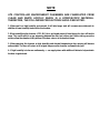
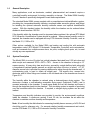
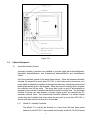
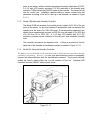
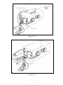
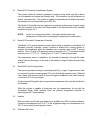
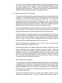
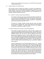
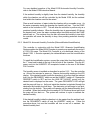
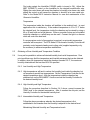
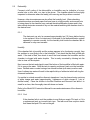
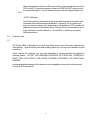
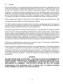
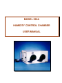
MODEL 506A
HUMIDITY CONTROL CHAMBER
USER MANUAL
NOTE
ets
CONTROLLED ENVIRONMENT CHAMBERS ARE FABRICATED FROM
CLEAR AND WHITE ACRYLIC WHICH IS A HYDROSCOPIC MATERIAL.
THEREFORE, THE FOLLOWING PRECAUTIONS SHOULD BE NOTED:
1. When used in a high humidity environment, it will take longer (and will consume more desiccant) to
stabilize at lower humidity levels within the chamber.
2. When humidifying the chamber (>75% RH) for a prolonged period of time, the acrylic door will tend to
warp. This could result in a gap appearing between the door and rubber seal. Before taking corrective
actions, allow the chamber to dry and see if the door returns to its standard shape.
3. When operating the chamber at high humidity and elevated temperatures door warping will become
quite evident. The door will return to its original shape once the chamber is allowed to dry out.
4. If high humidity is to be run continuously, ets can supply doors with additional latches to help maintain
the door to gasket seal.
1.0
General Description
Many applications, such as electronics, medical, pharmaceutical and research require a
controlled humidity environment for testing, assembly or storage. The Model 506A Humidity
Control Chamber is specifically designed to meet these requirements.
The standard Model 506A comes complete with a pump/desiccant dehumidification system,
circulating fan, temperature/humidity indicator, neoprene rubber accordion gloves, and fittings
for installing the optional automatic humidity controller sensor and optional humidification
system. With this standard system the humidity within the chamber can be reduced below
ambient to levels less than 10% RH.
If the humidity within the chamber must be increased above ambient, the optional ETS Model
5612 Ultrasonic Humidification System should be ordered. Where precise humidity control is
required, the chamber can be equipped with any ETS Automatic Humidity Controller, such as
the Model 511, 512B or 514.
Other options available for the Model 506A are heating and cooling kits with automatic
temperature control (ETS Model 513 Automatic Temperature Controller) and customization,
such as increased size, multiple access doors, iris ports, multiple gloves ports, etc, to meet
virtually any user requirement.
2.0
System Description
The Model 506A is a nine (9) cubic foot, airtight chamber fabricated from 0.25 inch clear and
white acrylic and measures 36”W x 24”D x 18”H. Access to the chamber is through a 12”
square opening. A heavy duty clear acrylic door, secured by a single half-turn latch, along with
a compression resistant gasket ensures an airtight seal when the door is locked. A 1.25”
diameter access hole is provided for passing cables and/or tubing through the chamber wall. A
non-hardening putty is used to obtain an airtight seal. The access door, access hole,
desiccator and all other fittings are located on the left-hand side of the chamber as shown in
Figure 2.0-1.
The humidity within the chamber is reduced using a desiccant/pump drying system. The
desiccator contains a self-indicating renewable drying agent (Anhydrous CaSO4) and is
mounted externally to the chamber. A small pump draws air from the chamber and forces it
through the desiccator back into the chamber. This circulating system is capable of producing
very low humidities within the chamber. If required, a nitrogen drying system can be used
instead.
Temperature and humidity indicators are provided to monitor the environmental conditions
inside the chamber. A continuous running 3 inch, 32 cfm, fan circulates the air within the
chamber to maintain a uniform humidity and temperature.
Note: At low humidity the dial indicator for measuring humidity has an accuracy of ±5% RH and
should be used for reference only. For accurate relative humidity measurement and control,
use the ETS Model 511, 512B or 514 Automatic Humidity Controllers.
1
Figure 2.0-1
3.0
Optional Equipment
3.1
Automatic Humidity Control
Automatic humidity controllers are available to provide single point dehumidification,
adjustable dehumidification and bi-directional dehumidification and humidification
control.
All of the controllers operate in the same basic manner. When the measured humidity
exceeds the set-point by more than 0.5% RH, a solid state control circuit turns on a
pump which circulates the chamber air through the desiccator, absorbing moisture and
lowering the humidity level in the chamber. When the set point humidity level is reached,
the controller turns off the pump. The pump then cycles on and off automatically as
required by the controller to maintain the desired set point humidity level. The Automatic
Humidity Controller can also operate a nitrogen drying system by controlling an AC
operated solenoid valve. The bi-directional controller operates in a similar manner
except when the humidity level drops below the set point by more than 0.5% RH, a
second solid state control circuit turns on a humidifier.
3.1.1
Model 511 Humidity Controller
The Model 511 controls the humidity to a fixed level that has been preset
between 5 and 30% RH. It can maintain the humidity to within 0.5% RH of the set
2
point, at the sensor, with an overall measurement accuracy better than ±5% RH.
A 3-1/2 digit LCD readout provides 0.1% RH resolution of the humidity level
indication. LEDs indicate the ON/OFF status of the controller. The sensor is built
into the control unit. Installation requires drilling a sensor access hole and
permanent mounting of the unit to the top of the chamber, as shown in Figure
3.1.1-1.
3.1.2
Model 512B Automatic Humidity Controller
The Model 512B can maintain the humidity level to within ±0.5% RH of the set
point, at the sensor, for any level between 0 and ambient, and can measure the
humidity over the entire 0 to 100% RH range. A fast responding capacitive type
sensor has a measurement accuracy of ±2% RH over the range of 0 to 90% and
±3% RH from 90 to 100% RH. A 3-1/2 digit LCD readout with 0.1% RH
resolution provides precise indication of the set point and measured humidity
level.
The controller and sensor are separate units. A fitting is provided on the lefthand side of the chamber for installing the sensor as shown in Figure 3.1.2-1.
3.1.3
Model 514 Automatic Humidity Controller
The Model 514 is a bi-directional version of the Model 512B. It utilizes the same sensor and has the same
performance specifications. However, it has two solid state switching circuits to separately
operate the dehumidification and the humidification systems. Front panel switches
enable the user to switch either one or both functions off and on. Individual LED
indicators show the ON/OFF status of each mode.
Figure 3.1.1-1
3
Figure 3.1.2-1
Figure 3.2-1
4
3.2
Model 5612 Ultrasonic Humidification System
This system utilizes an ultrasonic generator to produce a fine water mist that is blown
into the chamber to increase the humidity level. The humidifier is a self-contained unit
with its own water tank. The system is capable of maintaining the humidity level within
the chamber (at room temperature) up to 98% RH.
The Model 5612 installs onto the chamber by connecting a short piece of plastic tubing
from the humidifier to the inlet hose fitting located on the left-hand side of the chamber
as shown in Figure 3.2-1.
NOTE:
3.3
Acrylic is a hydroscopic material. Very high humidity and/or high
temperatures could cause a small degree of warping in the access door.
Model 513 Automatic Temperature Controller
The Model 513 is a bi-directional controller that is similar in operation to the Model 514
Automatic Humidity Controller, except it controls a heater and a cooling system to
maintain the temperature within the chamber over a nominal range of ±40 °F around
ambient. The 3-1/2 digit LCD readout provides a resolution of 0.1 °F with measurement
accuracy of ±1.8 °F (1.0 °C). Tracking is ±0.4 °F (±0.2 °C) about the set point.
The temperature sensor is installed in the chamber by passing it through the cable
access hole and mounting it to the side of the chamber using the adhesive-backed clip
provided.
3.4
Model 5613 Gas Cooling System
This system generates cooling by converting liquid CO2 to a gas. A high pressure valve
is connected to a tank containing liquid CO2 via a 48 inch high pressure hose. When the
valve opens, high pressure liquid is forced through an expansion valve which instantly
coverts the CO2 to a very cold gas.
A high pressure fitting which also incorporates the expansion valve must be retrofitted to
the chamber.
While this system is capable of producing very low temperatures, its use with the
uninsulated Model 506A chamber limits the practical temperature reduction to
approximately 40°F below ambient.
3.5
Heaters
Both convection and blower type heaters are available from ETS to heat the chamber.
Continuous temperatures up to 120 °F is the suggested range, but temperatures up to
150 °F can be used for short periods of time.
3.6
Extenders/Air Locks
5
Custom extenders and air locks are available that replace the access door. This
effectively increases the chamber volume and is useful when an increase in sample
storage or increased room for handling long objects is required. The extender can also
be configured as an airlock for applications where the environment within the chamber
must be precisely maintained at all times.
3.7
Desiccators/Desiccant
A 10 pound passive desiccator is available to allow the Model 506A chamber to be
used more effectively as a “dry box”. This desiccator is capable of maintaining the
humidity within the chamber to less than 5% RH. Also available is a 5 pound jar of
renewable indicating CASO4 desiccant.
3.8
Customized Chambers
Custom design chambers are also available to meet special customer requirements.
Custom designs may include, but are not limited to, over and under sized units,
additional access doors, multiple glove ports and special chamber material such as
antistatic acrylic, polycarbonate, PVC, etc.
4.0
SET-UP
4.1
Unpacking
Unpack the Humidity Test Chamber and the accessories from the shipping cartons and
inspect for any damage. When handling the chamber DO NOT use any of the fittings or
the door handle as a grip or for leverage. Lift the chamber by placing the hand all the
way into the glove port and grabbing hold of the chamber wall or gripping around the
outside of the chamber.
The standard chamber includes the following accessories:
1.
Pump (110V or 220 VAC)
2.
Desiccator
3.
Dial Temperature/Humidity Indicators
(Temperature Indicator only when ordered with Automatic Humidity
Controller)
4.
Clear Plastic Tubing - 2 each, 48 inches long
5.
Sealing compound
6.
Instruction Manual
4.2
Installation
Unlock the latch by turning the handle counterclockwise until the cam turns away from the
chamber wall and then open the access door. Place the required test instrumentation
inside the chamber and feed any cables through the 1.25” diameter hole located on the
left side next to the door. Take the soft sealing putty supplied and place it around the
cables and seal the hole. Make certain that the putty covers all of the cables and
creates an airtight seal.
6
Mount the desiccator to the left-hand side of the chamber by first loosening the two (2)
hex fittings, shown in Figure 4.2-1. Then insert the hose barb extensions on the
desiccator fully into the hex fittings and tighten with finger force.
Connect the pump to the chamber using the two (2) sections of clear plastic tubing as
shown in Figure 4.2-1. The “pressure” side of the pump is connected to the hex fitting.
Insert the tube at least one inch into the fitting and tighten with finger force. The “vacuum”
side of the pump is connected to the hose barb fitting.
If only the standard Model 506A configuration is being used, the pump is plugged
directly into the appropriate 115 or 230 volt, 50/60 Hz AC outlet. The pump is manually
operated by turning the power to the pump on and off. Plug the fan power cord into the
appropriate AC receptacle. It can be left on continuously to circulate the air throughout
the chamber. The Model 506A Humidity Control Chamber is now ready for use.
NOTE: The line voltage must be specified at the time of order so that the appropriate
pump and fan can be supplied.
4.3
Installation (Optional Extender/Air Lock)
The Extender/Air Lock is installed onto the chamber by removing the access door.
Remove the access door from the hinges and replace it with the Extender. The
Extender has drilled and tapped holes that mate with the hinge assembly.
The entire Extender swings open for gaining access to the full 12” x 12” chamber
opening. The smaller door on the Extender is now used to gain access to the chamber
during normal operation.
5.0
Operation
The Model 506A Humidity Control Chamber can be used to provide a controlled humidity
environment from less than 5% R H to 98% RH. Many applications, however, are at humidities
of less than 50%. The ability to obtain a given humidity is a function of the ambient conditions.
Very high ambient humidities (i.e., greater than 60% RH) have a significant affect in
maintaining humidity levels below 15%. On the other hand, low ambient humidities require
humidification within the chamber to obtain the desired humidity level.
5.1
Standard Humidity Chamber With Dial Temperature/Humidity Indicators
The standard Model 506A comes equipped with dial temperature/humidity indicators.
This type of indicator has a very slow response and can only be used in applications
where the humidity level remains constant and the exact level is not critical. In
applications requiring only a dry environment, the standard Model 506A configuration is
adequate.
5.1.1 Low Humidity (under 10%)
7
To obtain very low humidity conditions within the chamber, proceed as follows:
Turn on the pump and let it circulate the air through the external desiccator until
the lowest humidity level is reached. Place the optional 10 pound passive
desiccator inside the chamber. The humidity will be further reduced and the low
humidity condition will be maintained for a long period of time.
5.1.2 Moderate Humidity (10% to ambient)
The amount of dehumidification required is dependent upon the ambient humidity
conditions. If the ambient humidity is above the desired level, turn on the pump
and allow it to run until the humidity reaches the desired level. Let it continue to
run until the humidity is approximately 5% RH below this point. Turn off the pump.
Depending on the level of activity within the chamber and the integrity of the air
tight seal, the humidity will begin to rise slowly. When the humidity exceeds the
desired level by 5% RH turn the pump back on and repeat the cycle.
As the desiccant absorbs moisture its color will change from blue to pink starting
from the bottom of the desiccator. When the entire unit turns pink, the desiccant
should be regenerated in accordance with the procedure in Appendix A.
The effectiveness of the desiccant before it must be regenerated is a function of
how many times the chamber access door is opened and the ambient relative
humidity. Under normal conditions, a single desiccator unit should last between
one to five days. However, when the desiccator must absorb large amounts of
moisture the time between regeneration will be much shorter.
When the desiccant has reached the end of its life it will no longer absorb
moisture even though it is light blue in color.
If the desired humidity level is slightly greater than ambient, a small dish of water
with an adjustable cover should be placed inside the chamber. When the
humidity level inside the chamber reaches the desired level, the water dish
should be covered. If too much humidity is produced, turn on the pump for a short
period of time until the humidity level inside the chamber reaches the desired
level. Since the dial humidity indicator is slow in responding, it may be necessary
to repeat the above procedure several times.
High Humidity (above ambient)
To achieve high humidity (levels above ambient) insert a dish of water along with
an adjustable cover. When the humidity reaches the desired level cover the dish.
A small opening should be left to maintain the humidity. If the humidity goes
beyond the desired level, turn on the pump for a few moments to reduce the level.
This technique is only effective for increasing humidity levels up to 60% RH and
for short term applications.
The above procedures are only to be used if the chamber humidity is to be
altered on an occasional basis. If precise humidity control and/or a desire to
8
achieve varying humidity levels are required, one of the ETS Automatic Humidity
Controllers must be used.
5.2
Humidity Chamber with Humidity Control
ETS Automatic Humidity Controllers are capable of controlling and maintaining the
relative humidity level in the Model 506A Humidity Chamber to within 0.5% of the
desired set-point, at the sensor. Where the specification or application requires both
accurate humidity measurement and limited deviation from the specified level an
Automatic Humidity Controller must be used.
5.2.1 Model 511 Humidity Controller (Dehumidification)
This controller operates around a preset humidity level between 5 and 30% RH.
The set point can be adjusted between these limits by the user following the
procedure outlined in the Model 511 instructions. The Model 511 should only be
used when the chamber is dedicated to a single humidity level. Measurement
accuracy with this system is better than 5% RH.
The Model 511 Humidity Controller contains both the control and display
functions, and the humidity sensor. Holes must be drilled into the top and rear of
the chamber for installation. The hole locations and sizes, and installation
instructions are contained in the Model 511 manual.
5.2.2 Model 512B Automatic Humidity Controller (Dehumidification)
This controller can operate over the full 0 to 100% RH range. However, it can
only control the humidity to a level that is below ambient. The desired RH level is
selected by adjusting the RH SET control located on the front panel. Depress the
READ/SET switch to SET and then turn the SET ADJUST control until the
desired level is displayed on the meter. Set the PUMP ON/OFF switch to ON.
The red indicator will light and the pump will automatically turn on and circulate
the air in the chamber through the desiccator until the desired level is reached.
The pump will then automatically turn off and remain off until the humidity level
inside the chamber exceeds the set point by 0.5% RH. The pump will cycle on
and off to maintain the set level until the effectiveness of the desiccant is depleted
(pink indication).
Install the humidity sensor into the hex fitting shown in Figure 3.1.2-1. Push the
sensor into the fitting until the sensor grill is totally clear of the fitting inside the
chamber. Tighten the hex nut with finger force only. Remove the tape backing
from the Velcro and install the sensor electronics module above the hex fitting.
Plug the sensor cable connector into the SENSOR receptacle located on the rear
of the controller. Plug the pump AC power in to the AC receptacle also located at
the rear of the controller. Plug the fan power cord into the appropriate AC
receptacle. Turn the controller power on. If humidity indication only is desired,
turn the PUMP switch to OFF, otherwise leave the switch in the ON position.
When opening the access door for a period of time turn this switch off and unplug
the fan power cord to reduce drawing outside air into the chamber.
9
For more detailed operation of the Model 512B Automatic Humidity Controller,
refer to the Model 512B Instruction Manual.
If the ambient humidity is slightly lower than the desired humidity, the humidity
within the chamber can still be controlled by the Model 512B, but the ambient
level within the chamber must first be raised.
Place a small container of water inside the chamber with a moveable cover. As
the water evaporates inside the chamber the humidity will rise. Turn the PUMP
switch on the controller to OFF. This will allow the controller to perform only as a
precision humidity indicator. When the humidity rises to approximately 5% above
the desired level, cover the water container about two-thirds and turn the PUMP
switch back on. The moisture from the dish will cause the humidity to rise while
the controller will cause the humidity to drop, thus providing automatic humidity
control.
5.2.3 Model 514 Automatic Humidity Controller (Dehumidification/Humidification)
This controller in conjunction with the Model 5612 Ultrasonic Humidification
System enables the Model 506A Chamber to operate over practically the entire 0
to 100% RH range. The Model 514 Controller is a bi-directional version of the
Model 512B. It controls separately the dehumidification and the humidification
functions.
To install the humidification system, connect the output tube from the humidifier to
the 1” hose barb located at the top of the left side of the chamber. Plug the AC
power cord into the HUMIDIFY AC receptacle located on the rear of the Model
514 Controller.
The humidity sensor is installed as described in section 5.2.2. Turn the controller
on. Allow a few minutes for warm-up. Observe the humidity reading on the LCD
display. If the desired humidity inside the chamber is to be less than the ambient
level, turn the DEHUMIDIFY switch on and the HUMIDIFY switch off. Depress the
READ/SET switch to SET and turn the HUM SET ADJUST control until the
desired level is displayed on the meter. The green DEHUMIDIFY LED will light
and the pump will turn on. As the air inside the chamber is circulated through the
desiccator the humidity level will drop. The desiccator unit will begin to turn pink,
starting from the bottom. The system will operate until the desired humidity level
is reached. When the humidity level increases 0.5% RH above the set point level
the pump will turn back on. The system will continue to cycle to maintain the
desired humidity.
If the desired humidity inside the chamber is to be greater than the ambient level,
turn the DEHUMIDIFY switch off and the HUMIDIFY switch on. Follow the
procedure above, but now the humidifier will turn on and off to maintain the
desired humidity level.
10
First make certain the Humidifier POWER switch is turned to ON. Adjust the
MIST INTENSITY control on the humidifier for the desired humidification rate.
Sliding the control down will cause the chamber to humidify at a slower rate, while
sliding the control up will cause the chamber to humidify at a more rapid rate.
Refer to the Model 5612 Instruction Manual for care and maintenance of the
Ultrasonic Humidifier.
Temperature
The temperature inside the chamber will stabilize to the ambient level. In most
applications this is satisfactory. If the ambient temperature is 10 to 15 °F below
the desired level, the temperature inside the chamber can be raised by using a
40 or 60 watt bulb and a light dimmer. Either a porcelain fixture can be installed
inside the chamber or a small lamp can be used. Connect the light to a dimmer
which will control the heat level.
If a more precise control of temperature is required, an automatic temperature
controller will be required. The ETS Model 513 Automatic Humidity Controller will
precisely control separate heating and cooling units (supplied separately or by
the customer) to achieve temperature stabilization.
5.3
Obtaining a Given Humidity and Temperature Condition
5.4
It may not be possible to achieve all desired humidity levels at all temperatures. Dew
point conditions may limit the temperature and humidity extremes that can be obtained.
In addition, when the temperature inside the chamber exceeds 100 °F, the maximum
humidity obtainable will be less than 98% RH specified.
5.4.2 Low Humidity and High Temperature
5.4.3 High temperatures will tend to reduce the humidity level inside the chamber, but
not as severely as with low temperatures. Set the Temperature Controller for the
desired temperature level. After the temperature inside the chamber has
stabilized turn on the DEHUMIDIFY function and set the Humidity Controller for
the desired humidity level.
5.4.4 High Humidity and High Temperature
Follow the procedure described in Section 5.4.2 above, except increase the
TEMP level to the desired temperature. After it reaches the set-point, set the
Humidity Controller for the desired humidity level.
5.4.5 Intermediate Humidity and Temperature
Follow the above procedures whereby the desired temperature is first
established in the chamber then the humidity is adjusted to the desired level.
Maintaining Selected Humidity and Temperature Levels
11
5.5
Dehumidify
Frequent on/off cycling of the dehumidifier or humidifier may be indicative of a poor
access hole or door seal, or a tear in the gloves. The chamber should be thoroughly
inspected to determine where the leak(s) are occurring and the problem corrected.
However, other circumstances can also effect the humidity level. Water absorbing
materials such as wood and paper that have been in a high humidity environment prior
to being placed in the chamber may overload the dehumidification system and it may
take several desiccator renewals to dry out the material and bring the chamber down to
the desired level.
5.5.1
The desiccant can only be renewed approximately ten (10) times before having
to be replaced. Worn out desiccant is indicated by the dehumidification system
appearing to operate normally, but the humidity level inside the chamber fails to
decrease or may even increase.
Humidify
If the chamber fails to humidify and the system appears to be functioning correctly, then
the problem is most likely to be in the humidifier. First check that the tank is filled with
water. If the tank is filled, then check to see if the hose between the humidifier and the
chamber is clogged with water droplets. This is easily corrected by blowing into the
tube to clear out the droplets.
Next, remove the tank and check to see if the bottom of the humidifier is filled with water.
If it is, remove the water. Refill the tank to capacity and place it back onto the humidifier
base. Distilled water or water having a low mineral content (soft water) must be used.
Use of ordinary tap water will result in the rapid build-up of white dust which will clog the
ultrasonic transducer.
If a residue is noticed around the ultrasonic transducer it can be cleaned using a mixture
of white vinegar and water (approximately 1 tablespoon of white vinegar to 1 pint of
distilled water). Place the solution in the Mist Chamber and Reservoir and allow it to
stand for an hour, then thoroughly rinse with clean cool water.
Refer to the Model 5612 Instruction Manual for care and maintenance of the ultrasonic
humidifier.
5.5.2 Cool
If the chamber fails to cool the problem is most likely an empty CO2 tank, or if it is
a replacement tank, an incorrect tank type. The tank must have a siphon inside
that draws the liquid CO2 and not the gas.
12
When changing tanks, first shut off the main valve on the tank and then turn on the
COOL switch. (It may be necessary to lower the TEMP ADJUST setting so that
the solenoid activates.) This will release any pressure in the high pressure line.
5.5.3
NOTE: Calibration
As with all measuring instruments, the humidity and temperature indicators and
controllers should be periodically recalibrated. Generally, this is usually done
every six months or once a year, depending on the application. ETS provides full
calibration services for these instruments. Only the control unit and sensor need
to be returned for periodic calibration. Contact ETS to obtain the necessary
RMA authorization.
6.0
Chamber Care
7.0
The Model 506A is fabricated from clear and white acrylic using the finest materials and
workmanship. Care should be used when placing objects in or on top of the chamber to avoid
scratching.
When cleaning the chamber, use only mild detergents or cleaning solutions formulated for
cleaning plastics. DO NOT USE UNKNOWN SOLVENTS AS THESE MAY CHEMICALLY
REACT WITH THE ACRYLIC AND CAUSE CLOUDING, STREAKING, OR STRUCTURAL
DAMAGE.
Accidental physical damage to the chamber may be repairable using acrylic solvent cement.
Contact ETS for assistance.
13
8.0
Warranty
Electro-Tech Systems, Inc. warrants its equipment, accessories and parts of its manufacture to be and
remain free from defects in material and workmanship for a period of one (1) year from date of invoice
and will, at the discretion of Seller, either replace or repair without charge, F.O.B. Glenside, similar
equipment or a similar part to replace any equipment or part of its manufacture which, within the above
stated time, is proved to have been defective at the time it was sold. All equipment claimed defective
must be returned properly identified to the Seller (or presented to one of its agents for inspection).
This warranty only applies to equipment operated in accordance with Seller's operating instructions.
Seller's warranty with respect to those parts of the equipment which are purchased from other
manufacturers shall be subject only to that manufacturer's warranty.
The Seller's liability hereunder is expressly limited to repairing or replacing any parts of the equipment
manufactured by the manufacturer and found to have been defective. The Seller shall not be liable for
damage resulting or claimed to result from any cause whatsoever.
This warranty becomes null and void should the equipment, or any part thereof, be abused or modified
by the customer of if used in any application other than that for which it was intended. This warranty to
replace or repair is the only warranty, either expressed or implied or provided by law, and is in lieu of
all other warranties and the Seller denies any other promise, guarantee, or warranty with respect to the
equipment or accessories and, in particular, as to its or their suitability for the purposes of the buyer or
its or their performance, either quantitatively or qualitatively or as to the products which it may produce
and the buyer is expected to expressly waive rights to any warranty other than that stated herein.
ETS must be notified before any equipment is returned for repair. ETS will issue an RMA (Return
Material Authorization) number for return of equipment.
Equipment should be shipped prepaid and insured in the original packaging. If the original packaging
is not available, the equipment must be packed in a sufficiently large box (or boxes if applicable) of
double wall construction with substantial packing around all sides. The RMA number, description of
the problem along with the contact name and telephone number must be included in formal paperwork
and enclosed with the instrument. Round trip freight and related charges are the owner’s
responsibility.
WARNING
WOODEN CRATES MUST NOT BE USED. PACKAGING OF DELICATE INSTRUMENTS IN
WOODEN CRATES SUBSTANTIALLY INCREASES THE CONTENT’S SUSCEPTIBILITY TO
SHOCK DAMAGE.
DO NOT PLACE INSTRUMENTS OR ACCESSORIES INSIDE OTHER
INSTRUMENTS OR CHAMBERS. ELECTRO-TECH SYSTEMS, INC. WILL NOT ASSUME
RESPONSIBILITY FOR ADDITIONAL COST OF REPAIR DUE TO DAMAGE INCURRED
DURING SHIPMENT AS A RESULT OF POOR PACKAGING.
14
Appendix A
Specifications
1.
Column is molded acrylic plastic.
2.
Dimensions: 2 5/8” O.D. x 11 3/8”
3.
Anodized aluminum cap fitted with “O-Ring” gasket.
4.
Safe for working pressures to 90 psig.
5.
Desiccant supports and coil spring are of cadmium-plated steel.
6.
DRIERITE®* is held firmly in place between felt filters.
7.
Connections are for rubber tubing. Tubing should be held with hose clamps when used under
pressure.
8.
Filled with approximately 1¼ lbs. of 8 mesh Indicating DRIERITE.
9.
Capacity for water vapor up to 50 grams.
10.
Flow rate should be 200 liters per hour or 0.1 scfm for maximum efficiency.
11.
Air and gases dried to -100 °F dew point.
12.
Indicating DRIERITE is non-toxic and non-explosive.
Regeneration
DRIERITE granules should be removed from the column and spread evenly, one granule deep, on a
tray. Heat for one hour at about 200 °C or 400 °F. The desiccant should then be cooled in a tight
container before refilling the acrylic unit. Felt filters should also be pre-drilled at 100 °C for about 30
minutes before assembly.
*DRIERITE is the trade name for CASO4 of the W.A. Hammond Company.
15