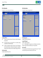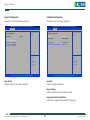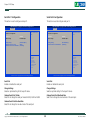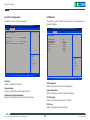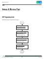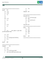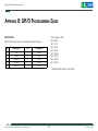
1
NEXCOM International Co., Ltd. Industrial Computing Solutions Embedded Computing (3.5” CPU Board) EBC 353 User Manual NEXCOM International Co., Ltd. Published May 2012 www.nexcom.com Content Contents Preface Precautions .............................................................................................5 Jumper Settings.......................................................................................6 Locations of the Jumpers and Connectors................................................7 Jumpers...................................................................................................8 CMOS Clear Select...............................................................................8 Power Mode Select...............................................................................8 LVDS Power Select ...............................................................................9 Panel Backlight Control Mode..............................................................9 Connector Pin Definitions......................................................................10 External I/O Interfaces.........................................................................10 DVI-I...............................................................................................10 COM1 Serial Port............................................................................10 USB0/1 Ports...................................................................................11 LAN1 Port.......................................................................................11 LAN2 Port ......................................................................................12 Internal Connectors............................................................................13 SMBus Connector...........................................................................13 Reset Button Connector..................................................................13 Power Button Connector.................................................................14 Speaker-out Connector...................................................................14 Mic-in Connector............................................................................15 Line-out Connector.........................................................................15 LED Connector................................................................................16 SATA DOM Power Connector .........................................................16 SIM Card External Connector..........................................................17 PS/2 Keyboard/Mouse Connector....................................................17 Copyright .............................................................................................. iv Disclaimer............................................................................................... iv Acknowledgements................................................................................ iv Regulatory Compliance Statements......................................................... iv Declaration of Conformity....................................................................... iv RoHS Compliance.................................................................................... v Warranty and RMA................................................................................. vi Safety Information.................................................................................viii Installation Recommendations................................................................viii Safety Precautions................................................................................... ix Technical Support and Assistance............................................................. x Conventions Used in this Manual............................................................. x Global Service Contact Information......................................................... xi Package Contents..................................................................................xiv Ordering Information..............................................................................xv Chapter 1: Product Introduction Overview.................................................................................................1 Key Features............................................................................................1 Hardware Specifications...........................................................................2 Knowing Your EBC 353...........................................................................4 Chapter 2: Jumpers and Connectors Before You Begin.....................................................................................5 Copyright © 2012 NEXCOM International Co., Ltd. All Rights Reserved. ii EBC 353 User Manual GPIO Connector .............................................................................18 Battery Connector...........................................................................18 SATA1 Connector............................................................................19 SATA2 Connector............................................................................19 SATA Power Connector...................................................................20 COM2 Connector...........................................................................20 COM3 Connector...........................................................................21 COM4 Connector...........................................................................21 CPU Fan Connector.........................................................................22 USB2/3 JST Connector.....................................................................22 USB4/5 JST Connector.....................................................................23 ATX Power Output Connector.........................................................23 LVDS Backlight Connector...............................................................24 LVDS Connector..............................................................................24 Mini-PCIe Slot.................................................................................25 PCI Slot...........................................................................................26 Sim Card Holder..............................................................................27 Block Diagram .................................................................................28 Board Dimensions ............................................................................29 Chapter 3: BIOS Setup About BIOS Setup..................................................................................30 When to Configure the BIOS..................................................................30 Default Configuration............................................................................31 Entering Setup.......................................................................................31 Legends.................................................................................................31 BIOS Setup Utility...................................................................................32 Main..................................................................................................32 Advanced...........................................................................................34 Chipset...............................................................................................40 Boot...................................................................................................42 Security..............................................................................................43 Save & Exit.........................................................................................44 Appendix A: Watchdog Timer WDT Programming Guide......................................................................45 Appendix B: GPI/O Programming Guide.....................47 Preface Preface Copyright Regulatory Compliance Statements This publication, including all photographs, illustrations and software, is protected under international copyright laws, with all rights reserved. No part of this manual may be reproduced, copied, translated or transmitted in any form or by any means without the prior written consent from NEXCOM International Co., Ltd. This section provides the FCC compliance statement for Class B devices and describes how to keep the system CE compliant. Declaration of Conformity FCC Disclaimer This equipment has been tested and verified to comply with the limits for a Class B digital device, pursuant to Part 15 of FCC Rules. These limits are designed to provide reasonable protection against harmful interference when the equipment is operated in a commercial environment. This equipment generates, uses, and can radiate radio frequency energy and, if not installed and used in accordance with the instructions, may cause harmful interference to radio communications. Operation of this equipment in a residential area (domestic environment) is likely to cause harmful interference, in which case the user will be required to correct the interference (take adequate measures) at their own expense. The information in this document is subject to change without prior notice and does not represent commitment from NEXCOM International Co., Ltd. However, users may update their knowledge of any product in use by constantly checking its manual posted on our website: http://www.nexcom.com. NEXCOM shall not be liable for direct, indirect, special, incidental, or consequential damages arising out of the use of any product, nor for any infringements upon the rights of third parties, which may result from such use. Any implied warranties of merchantability or fitness for any particular purpose is also disclaimed. Acknowledgements CE The product(s) described in this manual complies with all applicable European Union (CE) directives if it has a CE marking. For computer systems to remain CE compliant, only CE-compliant parts may be used. Maintaining CE compliance also requires proper cable and cabling techniques. EBC 353 is a trademark of NEXCOM International Co., Ltd. All other product names mentioned herein are registered trademarks of their respective owners. Copyright © 2012 NEXCOM International Co., Ltd. All Rights Reserved. iv EBC 353 User Manual Preface RoHS Compliance How to recognize NEXCOM RoHS Products? NEXCOM RoHS Environmental Policy and Status Update For existing products where there are non-RoHS and RoHS versions, the suffix “(LF)” will be added to the compliant product name. This publication, including all photographs, illustrations and software, is protected under international copyright laws, with all rights reserved. No part of this manual may be reproduced, copied, translated or transmitted in any form or by any means without the prior written consent from NEXCOM International Co., Ltd. All new product models launched after January 2006 will be RoHS compliant. They will use the usual NEXCOM naming convention. RoHS restricts the use of Lead (Pb) < 0.1% or 1,000ppm, Mercury (Hg) < 0.1% or 1,000ppm, Cadmium (Cd) < 0.01% or 100ppm, Hexavalent Chromium (Cr6+) < 0.1% or 1,000ppm, Polybrominated biphenyls (PBB) < 0.1% or 1,000ppm, and Polybrominated diphenyl Ethers (PBDE) < 0.1% or 1,000ppm. In order to meet the RoHS compliant directives, NEXCOM has established an engineering and manufacturing task force to implement the introduction of green products. The task force will ensure that we follow the standard NEXCOM development procedure and that all the new RoHS components and new manufacturing processes maintain the highest industry quality levels for which NEXCOM are renowned. The model selection criteria will be based on market demand. Vendors and suppliers will ensure that all designed components will be RoHS compliant. Copyright © 2012 NEXCOM International Co., Ltd. All Rights Reserved. v EBC 353 User Manual Preface Warranty and RMA NEXCOM Warranty Period Repair Service Charges for Out-of-Warranty Products NEXCOM manufactures products that are new or equivalent to new in accordance with industry standard. NEXCOM warrants that products will be free from defect in material and workmanship for 2 years, beginning on the date of invoice by NEXCOM. HCP series products (Blade Server) which are manufactured by NEXCOM are covered by a three year warranty period. NEXCOM will charge for out-of-warranty products in two categories, one is basic diagnostic fee and another is component (product) fee. Repair Service Charges for Out-of-Warranty Products NEXCOM will charge for out-of-warranty products in two categories, one is basic diagnostic fee and another is component (product) fee. NEXCOM Return Merchandise Authorization (RMA) ▪▪ Customers shall enclose the “NEXCOM RMA Service Form” with the returned packages. System Level ▪▪ Component fee: NEXCOM will only charge for main components such as SMD chip, BGA chip, etc. Passive components will be repaired for free, ex: resistor, capacitor. ▪▪ Customers must collect all the information about the problems encountered and note anything abnormal or, print out any on-screen messages, and describe the problems on the “NEXCOM RMA Service Form” for the RMA number apply process. ▪▪ Items will be replaced with NEXCOM products if the original one cannot be repaired. Ex: motherboard, power supply, etc. ▪▪ Customers can send back the faulty products with or without accessories (manuals, cable, etc.) and any components from the card, such as CPU and RAM. If the components were suspected as part of the problems, please note clearly which components are included. Otherwise, NEXCOM is not responsible for the devices/parts. ▪▪ Replace with 3rd party products if needed. ▪▪ Customers are responsible for the safe packaging of defective products, making sure it is durable enough to be resistant against further damage and deterioration during transportation. In case of damages occurred during transportation, the repair is treated as “Out of Warranty.” ▪▪ Component fee: NEXCOM will only charge for main components, such as SMD chip, BGA chip, etc. Passive components will be repaired for free, ex: resistors, capacitors. ▪▪ If RMA goods can not be repaired, NEXCOM will return it to the customer without any charge. Board Level ▪▪ If RMA goods can not be repaired, NEXCOM will return it to the customer without any charge. ▪▪ Any products returned by NEXCOM to other locations besides the customers’ site will bear an extra charge and will be billed to the customer. Copyright © 2012 NEXCOM International Co., Ltd. All Rights Reserved. vi EBC 353 User Manual Preface Warnings Read and adhere to all warnings, cautions, and notices in this guide and the documentation supplied with the chassis, power supply, and accessory modules. If the instructions for the chassis and power supply are inconsistent with these instructions or the instructions for accessory modules, contact the supplier to find out how you can ensure that your computer meets safety and regulatory requirements. Cautions Electrostatic discharge (ESD) can damage system components. Do the described procedures only at an ESD workstation. If no such station is available, you can provide some ESD protection by wearing an antistatic wrist strap and attaching it to a metal part of the computer chassis. Copyright © 2012 NEXCOM International Co., Ltd. All Rights Reserved. vii EBC 353 User Manual Preface Safety Information Installation Recommendations Before installing and using the device, note the following precautions: Ensure you have a stable, clean working environment. Dust and dirt can get into components and cause a malfunction. Use containers to keep small components separated. ▪▪ Read all instructions carefully. ▪▪ Do not place the unit on an unstable surface, cart, or stand. Adequate lighting and proper tools can prevent you from accidentally damaging the internal components. Most of the procedures that follow require only a few simple tools, including the following: ▪▪ Follow all warnings and cautions in this manual. ▪▪ When replacing parts, ensure that your service technician uses parts specified by the manufacturer. ▪▪ A Philips screwdriver ▪▪ A flat-tipped screwdriver ▪▪ Avoid using the system near water, in direct sunlight, or near a heating device. ▪▪ A grounding strap ▪▪ The load of the system unit does not solely rely for support from the rackmounts located on the sides. Firm support from the bottom is highly necessary in order to provide balance stability. ▪▪ An anti-static pad Using your fingers can disconnect most of the connections. It is recommended that you do not use needle-nose pliers to disconnect connections as these can damage the soft metal or plastic parts of the connectors. ▪▪ The computer is provided with a battery-powered real-time clock circuit. There is a danger of explosion if battery is incorrectly replaced. Replace only with the same or equivalent type recommended by the manufacturer. Discard used batteries according to the manufacturer’s instructions. Copyright © 2012 NEXCOM International Co., Ltd. All Rights Reserved. viii EBC 353 User Manual Preface Safety Precautions 11.If the equipment is not used for a long time, disconnect it from the power source to avoid damage by transient overvoltage. 1.Read these safety instructions carefully. 2.Keep this User Manual for later reference. 12.Never pour any liquid into an opening. This may cause fire or electrical shock. 3.Disconnect this equipment from any AC outlet before cleaning. Use a damp cloth. Do not use liquid or spray detergents for cleaning. 13.Never open the equipment. For safety reasons, the equipment should be opened only by qualified service personnel. 4.For plug-in equipment, the power outlet socket must be located near the equipment and must be easily accessible. 14.If one of the following situations arises, get the equipment checked by service personnel: a.The power cord or plug is damaged. b.Liquid has penetrated into the equipment. c.The equipment has been exposed to moisture. d.The equipment does not work well, or you cannot get it to work according to the user’s manual. e.The equipment has been dropped and damaged. f.The equipment has obvious signs of breakage. 5.Keep this equipment away from humidity. 6.Put this equipment on a stable surface during installation. Dropping it or letting it fall may cause damage. 7.The openings on the enclosure are for air convection to protect the equipment from overheating. DO NOT COVER THE OPENINGS. 15.Do not place heavy objects on the equipment. 8.Make sure the voltage of the power source is correct before connecting the equipment to the power outlet. 16.The unit uses a three-wire ground cable which is equipped with a third pin to ground the unit and prevent electric shock. Do not defeat the purpose of this pin. If your outlet does not support this kind of plug, contact your electrician to replace your obsolete outlet. 9.Place the power cord in a way so that people will not step on it. Do not place anything on top of the power cord. Use a power cord that has been approved for use with the product and that it matches the voltage and current marked on the product’s electrical range label. The voltage and current rating of the cord must be greater than the voltage and current rating marked on the product. 17. CAUTION: DANGER OF EXPLOSION IF BATTERY IS INCORRECTLY REPLACED. REPLACE ONLY WITH THE SAME OR EQUIVALENT TYPE RECOMMENDED BY THE MANUFACTURER. DISCARD USED BATTERIES ACCORDING TO THE MANUFACTURER’S INSTRUCTIONS. 10. All cautions and warnings on the equipment should be noted. Copyright © 2012 NEXCOM International Co., Ltd. All Rights Reserved. ix EBC 353 User Manual Preface Technical Support and Assistance Conventions Used in this Manual 1. For the most updated information of NEXCOM products, visit NEXCOM’s website at www.nexcom.com. Warning: Information about certain situations, which if not observed, can cause personal injury. This will prevent injury to yourself when performing a task. 2.For technical issues that require contacting our technical support team or sales representative, please have the following information ready before calling: – Product name and serial number – Detailed information of the peripheral devices –Detailed information of the installed software (operating system, version, application software, etc.) – A complete description of the problem – The exact wordings of the error messages CAUTION! Caution: Information to avoid damaging components or losing data. Note: Provides additional information to complete a task easily. Warning! 1.Handling the unit: carry the unit with both hands and handle it with care. 2.Maintenance: to keep the unit clean, use only approved cleaning products or clean with a dry cloth. 3.CompactFlash: Turn off the unit’s power before inserting or removing a CompactFlash storage card. Copyright © 2012 NEXCOM International Co., Ltd. All Rights Reserved. x EBC 353 User Manual Preface Global Service Contact Information Headquarters Taiwan Germany NEXCOM GmbH 15F, No. 920, Chung-Cheng Rd., ZhongHe District, New Taipei City, 23586, Taiwan, R.O.C. Tel: +886-2-8226-7786 Fax: +886-2-8226-7782 http://www.nexcom.com.tw Leopoldstraße Business Centre, Leopoldstraße 244, 80807 Munich, Germany Tel: +49-89-208039-278 Fax: +49-89-208039-279 http://www.nexcom.eu Italy NEXCOM ITALIA S.r.l USA NEXCOM USA Via Gaudenzio Ferrari 29, 21047 Saronno (VA), Italia Tel: +39 02 9628 0333 Fax: +39 02 9619 8846 http://www.nexcom.eu 3758 Spinnaker Court Fremont, CA, 94538, USA Tel: +1-510-656-2248 Fax: +1-510-656-2158 http://www.nexcom.com United Kingdom NEXCOM EUROPE France NEXCOM France 10 Vincent Avenue, Crownhill Business Centre, Milton Keynes, Buckinghamshire MK8 0AB, United Kingdom Tel: +44-1908-267121 Fax: +44-1908-262042 http://www.nexcom.eu Z.I. des Amandiers, 17, Rue des entrepreneurs, 78420 Carrières sur Seine, France Tel: +33 (0)1 71 51 10 20 Fax: +33 (0)1 71 51 10 21 http://www.nexcom.eu Copyright © 2012 NEXCOM International Co., Ltd. All Rights Reserved. xi EBC 353 User Manual Preface China NEXCOM China China-Wuhan Office 1-C1804/1805, Mingze Liwan, No. 519 South Luoshi Rd., Hongshan District, Wuhan, 430070, China Tel: +86-27-8722-7400 Fax: +86-27-8722-7400 http://www.nexcom.cn 2F, Block 4, Venus Plaza, Building 21, ZhongGuanCun Software Park, No. 8, Dongbeiwang West Road, Haidian District, Beijing, 100193, China Tel: +86-10-8282-5880 Fax: +86-10-8282-5955 http://www.nexcom.cn China-Chengdu Office 9F, Shuxiangxie,Xuefu Garden, No.12 Section 1, South Yihuan Rd., Chengdu, 610061,China Tel: +86-28-8523-0186 Fax: +86-28-8523-0186 http://www.nexcom.cn China-Shanghai Office Room 1505, Greenland He Chuang Building, No. 450 Caoyang Rd., Shanghai, 200062, China Tel: +86-21-6150-8008 Fax: +86-21-3251-6358 http://www.nexcom.cn China-Shenzhen Office Western Room 708, Block 210, Tairan Industry & Trading Place, Futian Area, Shenzhen, 518040, China TEL: +86-755-833 7203 FAX: +86-755-833 7213 http://www.nexcom.cn China-Nanjing Office Hall C, Block 17, Tian Xing Cui Lang Building, No. 49 Yunnan North Rd., Nanjing, 210018, China Tel: +86-25-8315-3486 Fax: +86-25-8315-3489 http://www.nexcom.cn Copyright © 2012 NEXCOM International Co., Ltd. All Rights Reserved. xii EBC 353 User Manual Preface Japan NEXCOM Japan 9F, Tamachi Hara Bldg., 4-11-5, Shiba Minato-ku, Tokyo, 108-0014, Japan Tel: +81-3-5419-7830 Fax: +81-3-5419-7832 http://www.nexcom-jp.com Copyright © 2012 NEXCOM International Co., Ltd. All Rights Reserved. xiii EBC 353 User Manual Preface Package Contents Before continuing, verify that the EBC 353 package that you received is complete. Your package should have all the items listed in the following table. EBC 353 Cable Kit (P/N: 10E00035302X0) Item Part Number 1 60233ATA73X00 2 60233DVI18X00 3 60233PS203X00 4 5 60233PW148X00 60233SIO62X00 Name SATA CABLE ACMELUX:19922413 DVI CABLE DVI-I TO DVI-I&D-SUB EDI:2A1292250101-RS EBC563IO PS2 KB/MS CABLE EDI:201061080201-RS SATA POWER CABLE BEST:901-0405-300R COMFORT CABLE CP:NEX-110819-01 6 60233USB59X00 USB CABLE EDI:262082060204-RS Description STANDARD L:300mm Qty 1 DVI Y CABLE DVI-I TO DVI-I L:100mm&D-SUB L:105mm 1 PS2 TO JST 8PIN 2.54mm L:200mm+-10mm 1 HOUSING 4P TO HOUSING 5P L:300mm UL2651 #28x9C-DB9+TU1001-10 L:200mm DUAL PORT USB CON TO JST 6PIN 2.0mm L:200+10mm 1 2 1 EBC 353/354 CPU Cooler (P/N: 10E00035301X0) Item Part Number 1 5044440090X00 2 5050300435X00 Name (H) THERMAL PAD APUS: 3A2015001001500 CPU HEATSINK FOR EBC352 SHYUNG SHUHN Copyright © 2012 NEXCOM International Co., Ltd. All Rights Reserved. xiv Description 15x10x1.5mm XR-PE 58x40x37mm 5800RPM 12V 2510 3PIN L:120mm Qty 1 1 EBC 353 User Manual Preface Ordering Information The following information below provides ordering information for EBC 353. EBC353-2550 (P/N: 10E00035303X0) RoHS Compliant Low power Embedded Board with Intel® Atom™ D2550 processor and based on Intel® integrated graphics engine w/ VGA/ 18-bit LVDS/ 6x USB2.0/ 4x COMs/ 1x Mini-PCIe/ 2x Gigabit LAN/ 2x SATA/ 1x PCI-104 Copyright © 2012 NEXCOM International Co., Ltd. All Rights Reserved. xv EBC 353 User Manual Chapter 1: Product Introduction Chapter 1: Product Introduction Overview Key Features ▪▪ Onboard Intel® Atom™ processor D2550 1.86GHz CPU ▪▪ Intel® NM10 Express chipset ▪▪ One 204-pin SO-DIMM socket supports up to 4 GB DDR3 800/1066 MHz SDRAM ▪▪ Display: VGA & DVI-D & LVDS (1x DF13 20-pin 18-bit Single channel) ▪▪ 1x Mini-PCIe ▪▪ 1x PCI-104 ▪▪ 2x Intel 82574L PCI Express Gigabit Ethernet ▪▪ 2x SATA ▪▪ 6x USB, 4-in/4-out GPIO, Mic-in, Line-out, Speaker-out ▪▪ Serial port: 3x RS232, 1x RS232/422/485 port ▪▪ Support AT/ATX mode and Single +12V DC input Copyright © 2012 NEXCOM International Co., Ltd. All Rights Reserved. 1 EBC 353 User Manual Chapter 1: Product Introduction Hardware Specifications ▪▪ Analog VGA interface – 1x VGA within DVI-I connector – resolution up to 1920x1200 75Hz ▪▪ DVI interface – 1x DVI-I connector – Resolution up to 1920x1200 ▪▪ LVDS interface – Single (24bit) LVDS panel, resolution up to 1440 x 900 DF13 20-pin LVDS connector for internal connection ▪▪ CCFL interface – 1x CCFL for LCD Panel Backlight Inverter (Analog/ PWM dimming support) CPU Support ▪▪ Intel Atom™ processor D2550 1.86GHz CPU ® Main Memory ▪▪ One 204-pin SO-DIMM socket supports up to 4 GB DDR3 800/1066 MHz SDRAM Chipset ▪▪ Intel® NM10 Express chipset BIOS ▪▪ ▪▪ ▪▪ ▪▪ ▪▪ AMI BIOS Plug & Play support Advanced Power Management Advanced Configuration & Power Interface 8M bits SPI ROM Audio ▪▪ Realtek ALC886 CODEC for High Definition ▪▪ 1x Mic-in and 1x Line-out Pin header On-board LAN Expansion ▪▪ 2x Intel® PCI Express Gigabit Ethernet ▪▪ Support Boot From LAN (PXE) ▪▪ 2x RJ45 with LED ▪▪ 1x Mini-PCIe ▪▪ 1x PCI-104 Display ▪▪ Intel® Atom™ processor D2550 integrated 3D graphics engine, which enhances Gfx & Video, support DX10.1, OpenGL 3.0, Full HD Decode (MPEG2,VC1,AVC,H.264), delivers sophisticated graphics for large display application, dual independent display support at graphics base frequency up to 640MHz, and provides a wealth of options for high-resolution displays Copyright © 2012 NEXCOM International Co., Ltd. All Rights Reserved. 2 EBC 353 User Manual Chapter 1: Product Introduction I/O Interface System Monitor ▪▪ Serial port: 4 ports – COM1 support RS232 with DB9 connector – COM2 support RS232/422/485 with 10-pin box connector – COM3,4 support RS232 with 10-pin box connector ▪▪ USB 2.0: 6 ports – 2 ports edge connector – 4 ports by 2.0mm JST connector ▪▪ 8 GPIO lines via header (GPI 0~3 and GPO0~3) TTL Level (0/5 V) ▪▪ On-board Power LED and HDD Active LED Pin Header ▪▪ 1x 4-pin fan connector (for CPU) ▪▪ 1x Keyboard/Mouse pin header ▪▪ On board Buzzer/SMBus2.0/Reset SW/On & Off switch button ▪▪ ▪▪ ▪▪ ▪▪ Edge I/O Interface ▪▪ Power requirement: +12V DC Input ▪▪ One 4-pin power connector ▪▪ ▪▪ ▪▪ ▪▪ Monitoring of 4 voltages and 2 temperatures 4 Voltage (Vcore, +12V , +3.3V , 5V) 2 Temperatures (CPU, System) 1 Fan Speed detection On-board RTC ▪▪ On-chip RTC with battery backup ▪▪ 1x External Li-Ion battery Power Input ▪▪ Support AT and ATX mode Power Requirements 1x DVI-I connector 1x COM1 support RS232 with DB9 connector 1x dual stack USB connector 2x RJ45 with LED connector Dimensions ▪▪ 3.5” ECX form factor/146mm (L) x 105mm (W) (5.7”x4.1”) Watchdog Timer Environment ▪▪ Watchdog timeout can be programmed by software from 1 second to 255 seconds, and from 1 minute to 255 minutes (Tolerance 15% under room temperature of 25°C). ▪▪ Operating temperatures: 0°C to 60°C ▪▪ Storage temperature: -20°C to 85°C ▪▪ Relative humidity: Operating 10% to 90%, non-condensing Storage Certifications ▪▪ 2x SATA port ▪▪ CE approval ▪▪ FCC Class A Copyright © 2012 NEXCOM International Co., Ltd. All Rights Reserved. 3 EBC 353 User Manual Chapter 1: Product Introduction Knowing Your EBC 353 COM2 CPU FAN COM1 SIM Card Slot COM3 K/B Mouse SATA2 SATA DOM Battery Connector SIM Card External GPIO CMOS SMBus Reset Power AT/ATX Select Intel NM10 ® Speaker-out Mic-in Line-out +12V DC Input LED DVI-I LVDS SATA Power LVDS Backlight Copyright © 2012 NEXCOM International Co., Ltd. All Rights Reserved. USB1 SATA1 USB2/3 4 LAN1 LAN2 USB4/5 EBC 353 User Manual Chapter 2: Jumpers and Connectors Chapter 2: Jumpers and Connectors This chapter describes how to set the jumpers and connectors on the EBC 353 motherboard. dry environments. A grounding strap is warranted whenever danger of static electricity exists. Before You Begin Precautions ▪▪ Ensure you have a stable, clean working environment. Dust and dirt can get into components and cause a malfunction. Use containers to keep small components separated. Computer components and electronic circuit boards can be damaged by discharges of static electricity. Working on computers that are still connected to a power supply can be extremely dangerous. ▪▪ Adequate lighting and proper tools can prevent you from accidentally damaging the internal components. Most of the procedures that follow require only a few simple tools, including the following: – A Philips screwdriver – A flat-tipped screwdriver – A set of jewelers screwdrivers – A grounding strap – An anti-static pad Follow the guidelines below to avoid damage to your computer or yourself: ▪▪ Always disconnect the unit from the power outlet whenever you are working inside the case. ▪▪ If possible, wear a grounded wrist strap when you are working inside the computer case. Alternatively, discharge any static electricity by touching the bare metal chassis of the unit case, or the bare metal body of any other grounded appliance. ▪▪ Using your fingers can disconnect most of the connections. It is recommended that you do not use needle-nosed pliers to disconnect connections as these can damage the soft metal or plastic parts of the connectors. ▪▪ Hold electronic circuit boards by the edges only. Do not touch the components on the board unless it is necessary to do so. Don’t flex or stress the circuit board. ▪▪ Before working on internal components, make sure that the power is off. Ground yourself before touching any internal components, by touching a metal object. Static electricity can damage many of the electronic components. Humid environments tend to have less static electricity than Copyright © 2012 NEXCOM International Co., Ltd. All Rights Reserved. ▪▪ Leave all components inside the static-proof packaging that they shipped with until they are ready for installation. ▪▪ Use correct screws and do not over tighten screws. 5 EBC 353 User Manual Chapter 2: Jumpers and Connectors Jumper Settings A jumper is the simplest kind of electric switch. It consists of two metal pins and a cap. When setting the jumpers, ensure that the jumper caps are placed on the correct pins. When the jumper cap is placed on both pins, the jumper is short. If you remove the jumper cap, or place the jumper cap on just one pin, the jumper is open. Refer to the illustrations below for examples of what the 2-pin and 3-pin jumpers look like when they are short (on) and open (off). Two-Pin Jumpers: Open (Left) and Short (Right) Three-Pin Jumpers: Pins 1 and 2 are Short 1 2 3 1 2 3 Copyright © 2012 NEXCOM International Co., Ltd. All Rights Reserved. 6 EBC 353 User Manual Chapter 2: Jumpers and Connectors Locations of the Jumpers and Connectors The figure below shows the location of the jumpers and connectors. J1 J2 CN2 J3 JP2 JP1 7 1 BZ1 1 7 U1 30 31 8 9 1 21 20 J5 10 2 JP3 J4 1 2 1 52 1 MH4 11 10 40 6 2 1 10 U2 1 24 1 5 2 1 JP4 51 4 10 PA1 H1 1 1 10 PD1 CN1 19 3 18 1 13 12 JP5 VER:B EBC353 4BE00353B1X10 MADE IN TAIWAN 49 48 U4 33 CN3 32 3 1 17 7 18 6 CN4 JP6 3 1 MH5 17 16 15 16 64 1 2 1 H2 1 JP9 37 3 1 1 36 48 25 12 13 JP10 24 5 U6 17 32 33 17 1 33 16 16 U11 32 1 7 5 3 9 17 15 13 11 21 25 23 AE AD AA Y W V U T R N L K J H G F D C B A 19 1 40 31 2 RT2 U8 31 30 29 27 26 25 24 23 22 21 20 19 18 16 14 13 12 11 10 9 8 7 5 4 3 2 1 30 1 JP8 AL AK AJ AH AG AE AD AC AB AA Y W V T P N M L K J H G F E D C B A 11 G 10 20 21 JP7 2 U7 4 JP11 49 64 1 CN5 PD30 1 48 48 49 U12 JP12 1 2 64 1 1 J6 CN6 2 4 J7 2 1 4 JP13 CON1 JP14 J8 7 19 1 20 8 H3 8 9 16 17 24 1 CN8 1 Copyright © 2012 NEXCOM International Co., Ltd. All Rights Reserved. 12 9 12 8 2 8 2 7 1 7 1 10 11 11 10 9 4 7 5 6 2 7 CN7 9 8 3 CN9 6 5 5 6 3 6 1 4 1 1 1 3 1 4 USB1 COM1 7 LAN1 H4 3 1 4 2 JP15 LAN2 EBC 353 User Manual Chapter 2: Jumpers and Connectors Jumpers CMOS Clear Select Power Mode Select Connector type: 1x3 3-pin header Connector location: JP4 Connector type: 1x3 3-pin header Connector location: JP9 1 3 Pin 1-2 On 2-3 On 1 Settings Normal Clear BIOS Pin 1-2 On 2-3 On 1-2 On: default Pin 1 2 3 3 Settings AT ATX 1-2 On: default Definition NC I_RTCRST# GND Copyright © 2012 NEXCOM International Co., Ltd. All Rights Reserved. Pin 1 2 3 8 Definition I_PWRBT# AT_PWRBT# ATX_BOT EBC 353 User Manual Chapter 2: Jumpers and Connectors LVDS Power Select Panel Backlight Control Mode Connector type: 1x3 3-pin header, 2.54mm pitch Connector location: JP14 Connector type: 2x3 6-pin header, 2.54mm pitch Connector location: JP13 1 3 Pin 1 2 3 Definition VCC3 PANEL1_VDD VCC5 2 6 1 5 Pin 1 2 3 4 5 6 1-2 On: default Definition CCFLBKLTCTRL CCFL_PWM PL_BKLTCTRL CCFLBKLTCTRL P_BKLTCTRL PWM_DUTY 1-3 On: Analog signal output for dimming control. (default) 3-5 On: PWM signal output for dimming control. Copyright © 2012 NEXCOM International Co., Ltd. All Rights Reserved. 9 EBC 353 User Manual Chapter 2: Jumpers and Connectors Connector Pin Definitions COM1 Serial Port External I/O Interfaces Connector type: DB-9 port Connector location: COM1 DVI-I Connector type: 1x3 3-pin header Connector location: JP4 Pin 1 3 5 7 9 11 13 15 17 19 21 23 C1 C3 C5A MH1 Definition CH_TX2_N DVI_I_GND NC DVI_I_DDC_D CH_TX1_N DVI_I_GND NC DVI_I_GND CH_TX0_N DVI_I_GND DDCDATA_VGA CH_CLK_P RED_VGA BLUE_VGA VGADET CHASIS_GND Pin 2 4 6 8 10 12 14 16 18 20 22 24 C2 C4 C5B MH2 Copyright © 2012 NEXCOM International Co., Ltd. All Rights Reserved. Definition CH_TX2_P NC DVI_I_DDC_C VSYNC_VGA CH_TX1_P NC DVI_I_5V HPDET_I CH_TX0_P DDCCLK_VGA DVI_I_GND CH_CLK_N GREEN_VGA HSYNC_VGA CRT_GND CHASIS_GND Pin 1 3 5 7 9 10 Definition SP1_DCD SP1_TXD GND SP1_RTS SP1_RI Pin 2 4 6 8 Definition SP1_RXD SP1_DTR SP1_DSR SP1_CTS EBC 353 User Manual Chapter 2: Jumpers and Connectors USB0/1 Ports LAN1 Port Connector type: Dual USB port, Type A Connector location: USB1 Connector type: RJ45 port with LEDs Connector location: LAN Pin 1 3 5 7 MH1 MH3 Definition P5V_USB_P01 USBCON_0P P5V_USB_P01 USBCON_1P USB1_MTH_GND USB1_MTH_GND Pin 2 4 6 8 MH2 MH4 Copyright © 2012 NEXCOM International Co., Ltd. All Rights Reserved. Definition USBCON_0N GND USBCON_1N GND USB1_MTH_GND USB1_MTH_GND Pin 1 3 5 7 9 11 MH1 11 Definition LAN1M0P LAN1M1P LAN1M2N LAN1M3P LAN1_LEDACT# LAN1_LINK100# CHASIS_GND Pin 2 4 6 8 10 12 MH2 Definition LAN1M0N LAN1M2P LAN1M1N LAN1M3N LAN1_ACTPW LAN1_LINK1G# CHASIS_GND EBC 353 User Manual Chapter 2: Jumpers and Connectors LAN2 Port Connector type: RJ45 port with LEDs Connector location: LAN2 Pin 1 3 5 7 9 11 MH1 Definition LAN2M0P LAN2M1P LAN2M2N LAN2M3P LAN2_LEDACT# LAN2_LINK100# CHASIS_GND Pin 2 4 6 8 10 12 MH2 Copyright © 2012 NEXCOM International Co., Ltd. All Rights Reserved. Definition LAN2M0N LAN2M2P LAN2M1N LAN2M3N LAN2_ACTPW LAN2_LINK1G# CHASIS_GND 12 EBC 353 User Manual Chapter 2: Jumpers and Connectors Internal Connectors Reset Button Connector SMBus Connector Connector type: 1x2 2-pin header, 2.00mm pitch Connector location: JP7 Connector type: 1x3 3-pin header 2.00mm-M-180 Connector location: JP6 1 1 2 3 Pin 1 2 3 Definition SMBCLK_MAIN SMBDATA_MAIN GND Copyright © 2012 NEXCOM International Co., Ltd. All Rights Reserved. Pin 1 2 13 Definition I_SYSRST# GND EBC 353 User Manual Chapter 2: Jumpers and Connectors Power Button Connector Speaker-out Connector Connector type: 1x2 2-pin header, 2.00mm pitch Connector location: JP8 Connector type: 1x5 5-pin header, 2.0mm pitch Connector location: JP10 1 2 Pin 1 2 1 Definition ATX_BOT GND Copyright © 2012 NEXCOM International Co., Ltd. All Rights Reserved. 5 Pin 1 2 3 4 5 14 Definition FRONT_L+ FRONT_LAGND FRONT_R+ FRONT_R EBC 353 User Manual Chapter 2: Jumpers and Connectors Mic-in Connector Line-out Connector Connector type: 1x4 4-pin header, 2.0mm pitch Connector location: JP11 Connector type: 1x4 4-pin header, 2.0mm pitch Connector location: JP12 1 4 Pin 1 2 3 4 1 Definition MIC_L3 AGND MIC_JD LOUT_R3 Copyright © 2012 NEXCOM International Co., Ltd. All Rights Reserved. 4 Pin 1 2 3 4 15 Definition LOUT_L2 AGND EXLINEOUT_JD LOUT_R2 EBC 353 User Manual Chapter 2: Jumpers and Connectors LED Connector SATA DOM Power Connector Connector type: 2x2 4-pin header, 2.0mm pitch Connector location: JP15 Connector type: 1x4 4-pin header, 2.0mm pitch Connector location: JP12 3 1 4 2 Pin 1 2 3 4 2 Definition PWRLEDP GND HDDLEDP GND Copyright © 2012 NEXCOM International Co., Ltd. All Rights Reserved. 1 Pin 1 2 16 Definition VCC5 GND EBC 353 User Manual Chapter 2: Jumpers and Connectors SIM Card External Connector PS/2 Keyboard/Mouse Connector Connector type: 2x3 6-pin header, 2.0mm pitch Connector location: JP1 Connector type: 2x4 8-pin header, 2.54mm Connector location: JP2 2 6 2 8 1 5 1 7 Pin 1 2 3 4 5 6 Definition UIM_PWR GND UIM_RESET UIM_VPP UIM_CLK UIM_DATA Copyright © 2012 NEXCOM International Co., Ltd. All Rights Reserved. Pin 1 2 3 4 5 6 7 8 17 Definition 5V_KB 5V_KB KDAT_R MDAT_R KCLK_R MCLK_R KBMS_GND KBMS_GND EBC 353 User Manual Chapter 2: Jumpers and Connectors GPIO Connector Battery Connector Connector type: 2x5 10-pin header, 2.0mm pitch Connector location: JP3 Connector type: 1x2 JST, 2-pin header, 2.5mm pitch Connector location: J5 2 10 1 9 Pin 1 2 3 4 5 6 7 8 9 10 1 Definition VCC5 GND SIO_GPO24 SIO_GPI20 SIO_GPO25 SIO_GPI21 SIO_GPO26 SIO_GPI22 SIO_GPO27 SIO_GPI23 Copyright © 2012 NEXCOM International Co., Ltd. All Rights Reserved. 2 Pin 1 2 18 Definition GND BAT_C EBC 353 User Manual Chapter 2: Jumpers and Connectors SATA1 Connector SATA2 Connector Connector type: Standard Serial ATAII 7P (1.27mm, SATA-M-180) Connector location: CN7 Connector type: Standard Serial ATAII 7P (1.27mm, SATA-M-180) Connector location: CN2 1 7 Pin 1 2 3 4 5 6 7 1 Definition GND SATA_TXP0_C SATA_TXN0_C GND SATA_RXN0_C SATA_RXP0_C GND Copyright © 2012 NEXCOM International Co., Ltd. All Rights Reserved. 7 Pin 1 2 3 4 5 6 7 19 Definition GND SATA_TXP1_C SATA_TXN1_C GND SATA_RXN1_C SATA_RXP1_C GND EBC 353 User Manual Chapter 2: Jumpers and Connectors SATA Power Connector COM2 Connector Connector type: 1x4 4-pin Wafer, 2.54mm pitch Connector location: CN8 Connector type: 1x10 10-pin header, 1.0mm pitch Connector location: J4 10 1 4 1 Pin 1 2 3 4 Definition +12V GND GND VCC5 Pin 1 4 7 10 Definition SP2_DCD SP2_DTR SP2_RTS GND Pin 2 5 8 Definition SP2_RXD GND SP2_CTS Pin 3 6 9 Definition SP2_TXD SP2_DSR SP2_RI Pin 2 5 8 Definition TXD+ GND CTS+ Pin 3 6 9 Definition RXD+ RTSCTS- Pin Definition TXD+ RXD+ Reserve Reserve Pin 3 4 7 Definition Reserve Reserve Reserve RS422 Pin Definition Pin 1 4 7 Definition TXDRXDRTS+ RS485 Pin Definition Pin 1 5 8 Copyright © 2012 NEXCOM International Co., Ltd. All Rights Reserved. 20 Definition TXDRXDReserve Reserve 2 6 9 EBC 353 User Manual Chapter 2: Jumpers and Connectors COM3 Connector COM4 Connector Connector type: 1x10 10-pin header 1.0mm pitch Connector location: J2 Connector type: 1x10 10-pin header, 1.0mm pitch Connector location: J1 Pin 1 2 3 4 5 6 7 8 9 10 10 10 1 1 Definition SP3_DCD SP3_RXD SP3_TXD SP3_DTR GND SP3_DSR SP3_RTS SP3_CTS SP3_RI GND Copyright © 2012 NEXCOM International Co., Ltd. All Rights Reserved. Pin 1 2 3 4 5 6 7 8 9 10 21 Definition SP4_DCD SP4_RXD SP4_TXD SP4_DTR GND SP4_DSR SP4_RTS SP4_CTS SP4_RI GND EBC 353 User Manual Chapter 2: Jumpers and Connectors CPU Fan Connector USB2/3 JST Connector Connector type: 1x4 4-pin Wafer, 2.54mm pitch Connector location: CN8 Connector type: 1x10 10-pin header, 1.0mm pitch Connector location: J4 6 4 1 Pin 1 2 3 4 1 Definition GND +12V CPUFANIN_R CPUFANOUT_R Copyright © 2012 NEXCOM International Co., Ltd. All Rights Reserved. Pin 1 2 3 4 5 6 22 Definition P5V_USB_P23 USBCON_2N USBCON_2P USBCON_3N USBCON_3P GND EBC 353 User Manual Chapter 2: Jumpers and Connectors USB4/5 JST Connector ATX Power Output Connector Connector type: 1x6 6-pin header, 2.0mm pitch Connector location: J8 Connector type: 2x2 Aux power connector Connector location: CON1 6 1 2 3 4 1 Pin 1 2 3 4 5 6 Definition P5V_USB_P45 USBCON_4N USBCON_4P USBCON_5N USBCON_5P GND Copyright © 2012 NEXCOM International Co., Ltd. All Rights Reserved. Pin 1 2 3 4 23 Definition GND GND +12V +12V EBC 353 User Manual Chapter 2: Jumpers and Connectors LVDS Backlight Connector LVDS Connector Connector type: 1x7 JST, 7-pin header, 2.5mm pitch Connector location: J6 Connector type: 2x10 20-pin header, 1.25mm pitch Connector location: CN6 1 2 7 19 20 1 Pin 1 2 3 4 5 6 7 Definition VCC5 V_INV(+12V) V_INV(+12V) BKLTCTRL GND GND M_BKLTEN_R Copyright © 2012 NEXCOM International Co., Ltd. All Rights Reserved. Pin 1 3 5 7 9 11 13 15 17 19 MH1 24 Definition M_LVDSDDCCLK VCC_LCD LVDS_CH_TX3_P LVDS_CH_TX3_N GND LVDS_CH _CLK_P LVDS_CH _CLK_N GND LVDS_CH_TX2_P LVDS_CH_TX2_N GND Pin 2 4 6 8 10 12 14 16 18 20 MH2 Definition M_LVDSDDCDATA LVDS_CH_TX0_P LVDS_CH_TX0_N VCC_LCD LVDS_CH_TX1_P LVDS_CH_TX1_N GND V_INV(+12V) V_INV (+12V) GND GND EBC 353 User Manual Chapter 2: Jumpers and Connectors Mini-PCIe Slot Connector location: CN4 1 2 51 52 Pin 1 3 5 7 9 11 13 15 17 19 21 23 25 Definition I_WAKE# NC NC MINICARD1CLKREQ# GND G_MINIPCIECLKN G_MINIPCIECLKN GND NC NC GND I_PERXN3 I_PERXP3 Pin 2 4 6 8 10 12 14 16 18 20 22 24 26 Copyright © 2012 NEXCOM International Co., Ltd. All Rights Reserved. Definition +3VSB_MINI1 GND 1V5 NC NC NC NC NC GND MINICARD1DIS# I_SLOTPLTRST# +3VSB_MINI1 GND Pin 27 29 31 33 35 37 39 41 43 45 47 49 51 25 Definition GND GND I_PETXN3_C I_PETXP3_C GND GND +3VSB_MINI1 +3VSB_MINI1 GND NC NC NC NC Pin 28 30 32 34 36 38 40 42 44 46 48 50 52 Definition 1V5 SMB_CLK SMB_DATA GND MINI1USBN MINI1USBP GND NC NC NC 1V5 GND +3VSB_MINI1 EBC 353 User Manual Chapter 2: Jumpers and Connectors PCI Slot Connector type: 120-pin H:9.6mm 180D GOLD FLASH DIP 5V Connector location: CN5 PA1 PD30 Pin Definition Pin Definition Pin PA1 GND PB1 NC PC1 PA2 VIO PB2 PCIAD2 PC2 PA3 PCIPCIAD5 PB3 GND PC3 PA4 PCICBE#0 PB4 PCIAD7 PC4 PA5 GND PB5 PCIAD9 PC5 PA6 PCIPCIAD11 PB6 VIO PC6 PA7 PCIAD14 PB7 PCIAD13 PC7 PA8 VCC3 PB8 PCICBE#1 PC8 PA9 SERR# PB9 GND PC9 PA10 GND PB10 PERR# PC10 PA11 STOP# PB11 VCC3 PC11 PA12 VCC3 PB12 TRDY# PC12 PA13 FRAME# PB13 GND PC13 PA14 GND PB14 PCIAD16 PC14 PA15 PCIAD18 PB15 VCC3 PC15 PD1 Definition VCC5 PCIAD1 PCIAD4 GND PCIAD8 PCIAD10 GND PCIAD15 NC VCC3 LOCK# GND IRDY# VCC3 PCIAD17 Copyright © 2012 NEXCOM International Co., Ltd. All Rights Reserved. Pin PD1 PD2 PD3 PD4 PD5 PD6 PD7 PD8 PD9 PD10 PD11 PD12 PD13 PD14 PD15 Definition PCIAD0 VCC5 PCIAD3 PCIAD6 GND GND PCIAD12 VCC3 PAR NC GND DEVSEL# VCC3 PCICBE#2 GND Pin Definition Pin Definition Pin Definition PA16 PCIAD21 PB16 PCIAD20 PC16 GND PA17 VCC3 PB17 PCIAD23 PC17 PCIAD22 PA18 IDSEL0 PB18 GND PC18 IDSEL1 PA19 PCIAD24 PB19 PCICBE#3 PC19 VIO PA20 GND PB20 PCIAD26 PC20 PCIAD25 PA21 PCIAD29 PB21 VCC5 PC21 PCIAD28 PA22 VCC5 PB22 PCIAD30 PC22 GND PA23 REQ#0 PB23 GND PC23 REQ#1 PA24 GND PB24 REQ#2 PC24 VCC5 PA25 GNT#1 PB25 VIO PC25 GNT2 PA26 VCC5 PB26 PCICLK0 PC26 GND PA27 PCICLK2 PB27 VCC5 PC27 PCICLK3 PA28 GND PB28 IRQD PC28 VCC5 PA29 +12V PB29 IRQA PC29 IRQB PA30 -12V PB30 REQ#3 PC30 GNT3 26 Pin PD16 PD17 PD18 PD19 PD20 PD21 PD22 PD23 PD24 PD25 PD26 PD27 PD28 PD29 PD30 Definition PCIAD19 VCC3 IDSEL2 IDSEL3 GND PCIAD27 PCIAD31 VIO GNT0 GND PCICLK1 GND PCIRST# IRQC GND EBC 353 User Manual Chapter 2: Jumpers and Connectors Sim Card Holder Connector location: CN3 C3 C2 C1 Pin C1 C2 C3 C4 C5 C6 C7 C6 C8 Definition UIM_PWR UIM_RESET UIM_CLK GND UIM_VPP UIM_DATA Copyright © 2012 NEXCOM International Co., Ltd. All Rights Reserved. 27 EBC 353 User Manual Chapter 2: Jumpers and Connectors Block Diagram CK505 CLOCK GEN HDMI DDI PORT1 DDI PORT0 VGA CedarView Dual Core CPU DX10.1 Graphics DDR3-800/1066 LVDS CON LVDS Page 12 13 HDA_SDI1 IHDA LVDS VGA Page 14 DDR3 800/1066 DVI-I CON Page 6 559 balls DDR3 DDR3 SO-DIMM Page 11 1 Slot 22*22mm Page 7-10 DMI DMI 4-5 - internal Page 20 6 - Mini Card Page 30 SATA Gen2 SATA Gen2 HDA_SDI0 SATA0 HDD Page 21 SATA1 DOM Page 21 SPI Tiger Point PCH NM10 360 balls 17*17mm Page 18-20 HDA LCI PCI 32 USB 2.0 SATA (2) USB 2.0 (8) Page 20 PCI-E *1(4) Page 20 2-3- internal Page 19 Page 21 2GB/s 0-1 - Rear MIC-IN SPI 2MB x2 DMI 2 Lanes PCIe x1 LAN 82574L Giga LAN PCIe x1 LAN 82574L Giga LAN PCIe x1 Mini PCIE PCI LPC Page 19 SPEAKER Audio Codec ALC886 Page 19 AMP TPS6047A4RHBR Page 19 Copyright © 2012 NEXCOM International Co., Ltd. All Rights Reserved. Page 24 3G RJ45 Page 23 RJ45 Page 25 Page 30 PCI104 2 master Page 29 LPC Bus 80 port Page 28 COM1/3/4 Page 29 RS-232 COM2 RS232/422/485 Page 30 Super I/O ITE8783 Page 28 HEAD PHONE Page 22 Page 19 Thermal Sensor *2 Voltages *4 FAN *1 Page 28 32 28 GPIO 4-IN/4-OUT Page 31 PS2 Page 32 EBC 353 User Manual Chapter 2: Jumpers and Connectors Board Dimensions Copyright © 2012 NEXCOM International Co., Ltd. All Rights Reserved. 29 EBC 353 User Manual Chapter 3: BIOS Setup Chapter 3: BIOS Setup This chapter describes how to use the BIOS setup program for the EBC 353. The BIOS screens provided in this chapter are for reference only and may change if the BIOS is updated in the future. The settings made in the setup program affect how the computer performs. It is important, therefore, first to try to understand all the setup options, and second, to make settings appropriate for the way you use the computer. To check for the latest updates and revisions, visit the NEXCOM Web site at www.nexcom.com.tw. When to Configure the BIOS ▪▪ This program should be executed under the following conditions: About BIOS Setup ▪▪ When changing the system configuration ▪▪ When a configuration error is detected by the system and you are prompted to make changes to the setup program The BIOS (Basic Input and Output System) Setup program is a menu driven utility that enables you to make changes to the system configuration and tailor your system to suit your individual work needs. It is a ROM-based configuration utility that displays the system’s configuration status and provides you with a tool to set system parameters. ▪▪ When resetting the system clock ▪▪ When redefining the communication ports to prevent any conflicts ▪▪ When making changes to the Power Management configuration These parameters are stored in non-volatile battery-backed-up CMOS RAM that saves this information even when the power is turned off. When the system is turned back on, the system is configured with the values found in CMOS. ▪▪ When changing the password or making other changes to the security setup Normally, CMOS setup is needed when the system hardware is not consistent with the information contained in the CMOS RAM, whenever the CMOS RAM has lost power, or the system features need to be changed. With easy-to-use pull down menus, you can configure such items as: ▪▪ Hard drives, diskette drives, and peripherals ▪▪ Video display type and display options ▪▪ Password protection from unauthorized use ▪▪ Power management features Copyright © 2012 NEXCOM International Co., Ltd. All Rights Reserved. 30 EBC 353 User Manual Chapter 3: BIOS Setup Default Configuration Legends Most of the configuration settings are either predefined according to the Load Optimal Defaults settings which are stored in the BIOS or are automatically detected and configured without requiring any actions. There are a few settings that you may need to change depending on your system configuration. Key Moves the highlight left or right to select a menu. Moves the highlight up or down between sub¬menus or fields. Entering Setup Exits the BIOS Setup Utility. When the system is powered on, the BIOS will enter the Power-On Self Test (POST) routines. These routines perform various diagnostic checks; if an error is encountered, the error will be reported in one of two different ways: Scrolls forward through the values or options of the highlighted field. Scrolls backward through the values or options of the highlighted field. ▪▪ If the error occurs before the display device is initialized, a series of beeps will be transmitted. Selects a field. ▪▪ If the error occurs after the display device is initialized, the screen will display the error message. Displays General Help. Load previous values. Powering on the computer and immediately pressing <Del> allows you to enter Setup. Another way to enter Setup is to power on the computer and wait for the following message during the POST: TO ENTER SETUP BEFORE BOOT PRESS Function Ctrl + Alt Load optimized default values. Saves and exits the Setup program. + Press <Enter> to enter the highlighted sub¬menu Press the key to enter Setup: Copyright © 2012 NEXCOM International Co., Ltd. All Rights Reserved. 31 EBC 353 User Manual Chapter 3: BIOS Setup BIOS Setup Utility Scroll Bar When a scroll bar appears to the right of the setup screen, it indicates that there are more available fields not shown on the screen. Use the up and down arrow keys to scroll through all the available fields. Submenu ▪▪ Once you enter the AMI BIOS Setup Utility, the Main Menu will appear on the screen. The main menu allows you to select from several setup functions and one exit. Use arrow keys to select among the items and press to accept or enter the submenu. When “” appears on the left of a particular field, it indicates that a submenu which contains additional options are available for that field. To display the submenu, move the highlight to that field and press . Main The Main menu is the first screen that you will see when you enter the BIOS Setup Utility. Aptio Setup Utility - Copyright (C) 2011 America Megatrends, Inc. Main Advanced BIOS Information BIOS Vendor Core Version Compliency Bios Version Build Date and Time Chipset Boot Security American Megatrends 4.6.5.1 UEFI 2.3; PI 1.2 E353-002 01/09/2012 15:21:01 Save & Exit Intel Reference Code version Intel RC Version System Date System Time [Thu 01/12/2012] [17:10:13] Access Level Administrator →←: Select Screen ↑↓: Select Item Enter: Select +/-: Change Opt. F1: General Help F2: Previous Values F3: Optimized Defaults F4: Save & Exit ESC: Exit Version 2.14.1219. Copyright (C) 2011 American Megatrends, Inc. Copyright © 2012 NEXCOM International Co., Ltd. All Rights Reserved. 32 EBC 353 User Manual Chapter 3: BIOS Setup Intel RC Version System Time Displays the Intel Reference Code version. The time format is <hour>, <minute>, <second>. The time is based on the 24-hour military-time clock. For example, 1 p.m. is 13:00:00. Hour displays hours from 00 to 23. Minute displays minutes from 00 to 59. Second displays seconds from 00 to 59. Aptio Setup Utility - Copyright (C) 2011 America Megatrends, Inc. Main INTEL INTEL INTEL INTEL INTEL INTEL CEDARVIEW MRC NM10 P-UINT IGFX VBIOS ACPI 0.9.0-1 1.00 1.6.0 012 1053 0.9.0-1 Intel Reference Code version Access Level Displays the access level of the current user in the BIOS. →←: Select Screen ↑↓: Select Item Enter: Select +/-: Change Opt. F1: General Help F2: Previous Values F3: Optimized Defaults F4: Save & Exit ESC: Exit Version 2.14.1219. Copyright (C) 2011 American Megatrends, Inc. System Date The date format is <day>, <month>, <date>, <year>. Day displays a day, from Monday to Sunday. Month displays the month, from January to December. Date displays the date, from 1 to 31. Year displays the year, from 1999 to 2099. Copyright © 2012 NEXCOM International Co., Ltd. All Rights Reserved. 33 EBC 353 User Manual Chapter 3: BIOS Setup Advanced Launch LAN1/2 PXE OpROM Enables or disables the boot option for legacy network devices connected to LAN1 and LAN2. The Advanced menu allows you to configure your system for basic operation. Some entries are defaults required by the system board, while others, if enabled, will improve the performance of your system or let you set some features according to your preference. Setting incorrect field values may cause the system to malfunction. Aptio Setup Utility - Copyright (C) 2011 America Megatrends, Inc. Main Advanced Chipset Legacy OpROM Support Launch Lan1 PXE OpROM Launch Lan2 PXE OpROM Boot Security [Disabled] [Disabled] Save & Exit Enable or Disable Boot Option for Lan1. CPU Configuration IDE Configuration USB Configuration Super IO Configuration H/W Monitor →←: Select Screen ↑↓: Select Item Enter: Select +/-: Change Opt. F1: General Help F2: Previous Values F3: Optimized Defaults F4: Save & Exit ESC: Exit Version 2.14.1219. Copyright (C) 2011 American Megatrends, Inc. Copyright © 2012 NEXCOM International Co., Ltd. All Rights Reserved. 34 EBC 353 User Manual Chapter 3: BIOS Setup CPU Configuration Limit CPUID Maximum This section is used to configure the CPU. The CPUID instruction of some newer CPUs will return a value greater than 3. The default is Disabled because this problem does not exist in the Windows series operating systems. If you are using an operating system other than Windows, this problem may occur. To avoid this problem, enable this field to limit the return value to 3 or lesser than 3. Aptio Setup Utility - Copyright (C) 2011 America Megatrends, Inc. Advanced CPU Configuration Processor Type EMT64 Processor Speed System Bus Speed Rat io Status Actual Ratio System Bus Speed Processor Stepping Microcode Revision L1 Cache RAM L2 Cache RAM Processor Core Hyper-Threading Intel(R) Atom(TM) CPU Supported 2132 MHz 533MHz 16 16 533 MHz 30661 262 2x56 k 2x 512k Dual Supported Hyper-Threading Execute Disable Bit Limit CPUID Maximum [Enabled] [Enabled] [Disabled] Enabled for Windows XP and Linux (OS optimized for Hyper-Threading Technology) and Disabled for other OS (OS not optimized for Hyper-Threading Technology). →←: Select Screen ↑↓: Select Item Enter: Select +/-: Change Opt. F1: General Help F2: Previous Values F3: Optimized Defaults F4: Save & Exit ESC: Exit Version 2.14.1219. Copyright (C) 2011 American Megatrends, Inc. Hyper-threading Disable or Enable hyper-threading technology. Execute Disable Bit When this field is set to Disabled, it will force the XD feature flag to always return to 0. XD can prevent certain classes of malicious buffer overflow attacks when combined with a supporting OS (Windows Server 2003 SP1, Windows XP SP2, SuSE Linux 9.2, RedHat Enterprise 3 Update 3). Copyright © 2012 NEXCOM International Co., Ltd. All Rights Reserved. 35 EBC 353 User Manual Chapter 3: BIOS Setup IDE Configuration USB Configuration This section is used to configure the IDE drives. This section is used to configure the USB. Aptio Setup Utility - Copyright (C) 2011 America Megatrends, Inc. Aptio Setup Utility - Copyright (C) 2011 America Megatrends, Inc. Advanced Advanced Not Present Not Present SATA Port0 SATA Port1 SATA Controller(s) [Enabled] Configure SATA as [AHCI] USB Configuration SATA Ports (0-3) Device Names if Present and Enabled. Enables Legacy USB support. AUTO option disables legacy Support if no USB devices are connected. DISABLE option will keep USB devices available only for EFI applications. USB Devices: None Legacy USB Support EHCI Hand-off Device reset time-out [Enabeld] [Disabled] [20 sec] →←: Select Screen ↑↓: Select Item Enter: Select +/-: Change Opt. F1: General Help F2: Previous Values F3: Optimized Defaults F4: Save & Exit ESC: Exit →←: Select Screen ↑↓: Select Item Enter: Select +/-: Change Opt. F1: General Help F2: Previous Values F3: Optimized Defaults F4: Save & Exit ESC: Exit Version 2.14.1219. Copyright (C) 2011 American Megatrends, Inc. Version 2.14.1219. Copyright (C) 2011 American Megatrends, Inc. Configure SATA As USB Configuration IDE Displays the detected USB devices. This option configures the Serial ATA drives as Parallel ATA physical storage device. Legacy USB Support RAID This option allows you to create RAID or Intel Matrix Storage configuration on Serial ATA devices. Enable Enables Legacy USB. Auto Disables support for Legacy when no USB devices are connected. Disable Keeps USB devices available only for EFI applications. AHCI This option configures the Serial ATA drives to use AHCI (Advanced Host Controller Interface). AHCI allows the storage driver to enable the advanced Serial ATA features which will increase storage performance. EHCI Hand-Off This is a workaround for OSs that does not support EHCI hand-off. The EHCI ownership change should be claimed by the EHCI driver. SATA Controller(s) Enables or disables SATA ports 0-3. Copyright © 2012 NEXCOM International Co., Ltd. All Rights Reserved. 36 EBC 353 User Manual Chapter 3: BIOS Setup Super IO Configuration Serial Port 0 Configuration This section is used to configure the serial ports. This section is used to configure serial port 0. Aptio Setup Utility - Copyright (C) 2011 America Megatrends, Inc. Aptio Setup Utility - Copyright (C) 2011 America Megatrends, Inc. Advanced Advanced Super IO Configuration IT8783F Super IO Chip Serial Serial Serial Serial Port Port Port Port 0 1 2 2 Serial Port 0 Configuration Set Parameters of Serial Port O (COMA) Configuration Configuration Configuration Configuration Enable or Disable Serial Port (COM) Serial Port Device Settings [Enabled] IO=3F8h; IRQ=4; Change Settings Onboard Serial Port Max Baud Rate [IO=3F8h; IRQ=4;] [115200 bps] →←: Select Screen ↑↓: Select Item Enter: Select +/-: Change Opt. F1: General Help F2: Previous Values F3: Optimized Defaults F4: Save & Exit ESC: Exit →←: Select Screen ↑↓: Select Item Enter: Select +/-: Change Opt. F1: General Help F2: Previous Values F3: Optimized Defaults F4: Save & Exit ESC: Exit Version 2.14.1219. Copyright (C) 2011 American Megatrends, Inc. Version 2.14.1219. Copyright (C) 2011 American Megatrends, Inc. Super IO Chip Serial Port Displays the Super I/O chip used on the board. Enables or disables the serial port. Change Settings Selects an optimal setting for the Super IO device. Onboard Serial Port Max Baud Rate Select this to change the max baud rate of the serial port. Copyright © 2012 NEXCOM International Co., Ltd. All Rights Reserved. 37 EBC 353 User Manual Chapter 3: BIOS Setup Serial Port 1 Configuration Serial Port 2 Configuration This section is used to configure serial port 1. This section is used to configure serial port 2. Aptio Setup Utility - Copyright (C) 2011 America Megatrends, Inc. Aptio Setup Utility - Copyright (C) 2011 America Megatrends, Inc. Advanced Advanced Serial Port 1 Configuration Serial Port 2 Configuration Enable or Disable Serial Port (COM) Enable or Disable Serial Port (COM) Serial Port Device Settings [Enabled] IO=2F8h; IRQ=3; Serial Port Device Settings [Enabled] IO=3F8h; IRQ=7; Change Settings Onboard Serial Port 1 Mode Onboard Serial Port Max Baud Rate [IO=2F8h; IRQ=3;] [RS232] [115200 bps] Change Settings Onboard Serial Port Max Baud Rate [IO=3F8h; IRQ=7;] [115200 bps] →←: Select Screen ↑↓: Select Item Enter: Select +/-: Change Opt. F1: General Help F2: Previous Values F3: Optimized Defaults F4: Save & Exit ESC: Exit →←: Select Screen ↑↓: Select Item Enter: Select +/-: Change Opt. F1: General Help F2: Previous Values F3: Optimized Defaults F4: Save & Exit ESC: Exit Version 2.14.1219. Copyright (C) 2011 American Megatrends, Inc. Version 2.14.1219. Copyright (C) 2011 American Megatrends, Inc. Serial Port Serial Port Enables or disables the serial port. Enables or disables the serial port. Change Settings Change Settings Selects an optimal setting for the Super IO device. Selects an optimal setting for the Super IO device. Onboard Serial Port 1 Mode Onboard Serial Port Max Baud Rate Select this to change the serial port mode to RS232, RS422 or RS485. Select this to change the max baud rate of the serial port. Onboard Serial Port Max Baud Rate Select this to change the max baud rate of the serial port. Copyright © 2012 NEXCOM International Co., Ltd. All Rights Reserved. 38 EBC 353 User Manual Chapter 3: BIOS Setup Serial Port 3 Configuration H/W Monitor This section is used to configure serial port 3. This section is used to monitor hardware status such as temperature, fan speed and voltages. Aptio Setup Utility - Copyright (C) 2011 America Megatrends, Inc. Advanced Aptio Setup Utility - Copyright (C) 2011 America Megatrends, Inc. Serial Port 3 Configuration Advanced Enable or Disable Serial Port (COM) Serial Port Device Settings [Enabled] IO=2F8h; IRQ=6; Change Settings Onboard Serial Port Max Baud Rate [IO=2F8h; IRQ=6;] [115200 bps] PC Health Status CPU Temperature System Temperature CPU FAN Speed CPU: Vcore +3.3V +5V +12V : : : : : : : +34C +24C 6368 RPM +1.168V +3.264V +5.017V +11.827V →←: Select Screen ↑↓: Select Item Enter: Select +/-: Change Opt. F1: General Help F2: Previous Values F3: Optimized Defaults F4: Save & Exit ESC: Exit →←: Select Screen ↑↓: Select Item Enter: Select +/-: Change Opt. F1: General Help F2: Previous Values F3: Optimized Defaults F4: Save & Exit ESC: Exit Version 2.14.1219. Copyright (C) 2011 American Megatrends, Inc. Version 2.14.1219. Copyright (C) 2011 American Megatrends, Inc. Serial Port CPU Temperature Enables or disables the serial port. Detects and displays the current CPU temperature. Change Settings System Temperature Selects an optimal setting for the Super IO device. Detects and displays the current system temperature. Onboard Serial Port Max Baud Rate CPU FAN Speed Select this to change the max baud rate of the serial port. Detects and displays the current CPU fan speed. CPU: Vcore Detects and displays the output voltages. Copyright © 2012 NEXCOM International Co., Ltd. All Rights Reserved. 39 EBC 353 User Manual Chapter 3: BIOS Setup Chipset Host Bridge This section gives you functions to configure the system based on the specific features of the chipset. The chipset manages bus speeds and access to system memory resources. This section is used to configure the host bridge features. Aptio Setup Utility - Copyright (C) 2011 America Megatrends, Inc. Chipset Aptio Setup Utility - Copyright (C) 2011 America Megatrends, Inc. Main Advanced Chipset Boot Security Host Bridge South Bridge Save & Exit Intel IGD Configuration Config Intel IGD Settings. ******* Memory Information ******* 1067 MHz(DDR3) Memory Frequency 4096 MB Total Memory Not Present DIMM#0 4096 MB DIMM#1 Host Bridge Parameters →←: Select Screen ↑↓: Select Item Enter: Select +/-: Change Opt. F1: General Help F2: Previous Values F3: Optimized Defaults F4: Save & Exit ESC: Exit →←: Select Screen ↑↓: Select Item Enter: Select +/-: Change Opt. F1: General Help F2: Previous Values F3: Optimized Defaults F4: Save & Exit ESC: Exit Version 2.14.1219. Copyright (C) 2011 American Megatrends, Inc. Version 2.14.1219. Copyright (C) 2011 American Megatrends, Inc. Intel IGD Configuration Configures the options for Intel IGD function. Memory Information Detects and displays information on the memory installed in the system. Copyright © 2012 NEXCOM International Co., Ltd. All Rights Reserved. 40 EBC 353 User Manual Chapter 3: BIOS Setup South Bridge Restore AC Power Loss This section is used to configure the south bridge features. Power Off When power returns after an AC power failure, the system’s power is off. You must press the power button to power-on the system. Power On When power returns after an AC power failure, the system will automatically power-on. Last State When power returns after an AC power failure, the system will return to the state where you left off before power failure occurs. If the system’s power is off when AC power failure occurs, it will remain off when power returns. If the system’s power is on when AC power failure occurs, the system will power-on when power returns. Aptio Setup Utility - Copyright (C) 2011 America Megatrends, Inc. Chipset Azalia Controller SMBus Controller [HD Audio] [Enabled] Azalia Controller Hight Precision Event Timer Configuration [Enabled] Hight Precision Timer Restore AC Power Loss [Last State] →←: Select Screen ↑↓: Select Item Enter: Select +/-: Change Opt. F1: General Help F2: Previous Values F3: Optimized Defaults F4: Save & Exit ESC: Exit Version 2.14.1219. Copyright (C) 2011 American Megatrends, Inc. Azalia Controller Enables or disables the Azalia HD audio. SMBus Controller Enables or disables the SMBus controller. High Precision Timer Enables or disables the high precision event timer. Copyright © 2012 NEXCOM International Co., Ltd. All Rights Reserved. 41 EBC 353 User Manual Chapter 3: BIOS Setup Boot Quiet Boot Enabled Displays OEM logo instead of the POST messages. DisabledDisplays normal POST messages. This section is used to configure the boot features. Aptio Setup Utility - Copyright (C) 2011 America Megatrends, Inc. Main Advanced Chipset Boot Security Boot Configuration Setup Prompt Timeout Boothup NumLock State 1 [On] Quiet Boot [Disabled] CMS16 Module Version 07.65 GateA20 Active Option ROM Messages Interrupt 19 Capture [Upon Request] [Force BIOS] [Disabled] Save & Exit Gate A20 Active Upon Request GA20 can be disabled using BIOS services Always Does not allow disabling GA20. This option is useful when an RT code is executed above 1M. Number of seconds to wait for setup activation key. 65535(0xFFFF) means indefinite waiting. Option ROM Messages Selects the display mode for Option ROM. The options are Force BIOS and Keep Current. Interrupt 19 Capture →←: Select Screen ↑↓: Select Item Enter: Select +/-: Change Opt. F1: General Help F2: Previous Values F3: Optimized Defaults F4: Save & Exit ESC: Exit When enabled, it allows the optional ROM to trap interrupt 19. Boot Option Priorities Adjust the boot sequence of the system. Boot Option #1 is the first boot device that the system will boot from, next will be #2 and so forth. Version 2.14.1219. Copyright (C) 2011 American Megatrends, Inc. Setup Prompt Timeout Selects the number of seconds to wait for the setup activation key. 65535(0xFFFF) denotes indefinite waiting. Bootup NumLock State This allows you to determine the default state of the numeric keypad. By default, the system boots up with NumLock on wherein the function of the numeric keypad is the number keys. When set to Off, the function of the numeric keypad is the arrow keys. Copyright © 2012 NEXCOM International Co., Ltd. All Rights Reserved. 42 EBC 353 User Manual Chapter 3: BIOS Setup Security Administrator Password Aptio Setup Utility - Copyright (C) 2011 America Megatrends, Inc. Main Advanced Chipset Boot Security Password Description If ONLY the Administrator’s password is set, then this only limits access to Setup and is only asked for when entering Setup. If ONLY the User’s password is set, then this is a power on password and must be entered to boot or enter Setup. In Setup the User Will have Administrator rights. The password length must be in the following range: Minimum length 3 Maximum length 20 Administrator Password User Password Select this to reconfigure the administrator’s password. Save & Exit Set Administrator Password User Password Select this to reconfigure the user’s password. →←: Select Screen ↑↓: Select Item Enter: Select +/-: Change Opt. F1: General Help F2: Previous Values F3: Optimized Defaults F4: Save & Exit ESC: Exit Version 2.14.1219. Copyright (C) 2011 American Megatrends, Inc. Copyright © 2012 NEXCOM International Co., Ltd. All Rights Reserved. 43 EBC 353 User Manual Chapter 3: BIOS Setup Save & Exit Save Changes and Reset To save the changes and reset, select this field then press <Enter>. A dialog box will appear. Confirm by selecting Yes. Aptio Setup Utility - Copyright (C) 2011 America Megatrends, Inc. Main Advanced Chipset Boot Security Save Changes and Exit Save & Exit Discard Changes and Reset To exit the Setup utility without saving the changes, select this field then press <Enter>. You may be prompted to confirm again before exiting. Exti system setup after saving the changes. Discard Changes and Exit Save Changes and Reset Discard Changes and Reset Save Changes To save changes and continue configuring the BIOS, select this field then press <Enter>. A dialog box will appear. Confirm by selecting Yes. Save Options Save Changes Discard Changes Restore Defaults Save as User Defaults Restore User Defaults Boot Override Lanuch EFI Shell from filesystem device Discard Changes To discard the changes, select this field then press <Enter>. A dialog box will appear. Confirm by selecting Yes to discard all changes made and restore the previously saved settings. →←: Select Screen ↑↓: Select Item Enter: Select +/-: Change Opt. F1: General Help F2: Previous Values F3: Optimized Defaults F4: Save & Exit ESC: Exit Restore Defaults To restore the BIOS to default settings, select this field then press <Enter>. A dialog box will appear. Confirm by selecting Yes. Save as User Defaults To use the current configurations as user default settings for the BIOS, select this field then press <Enter>. A dialog box will appear. Confirm by selecting Yes. Version 2.14.1219. Copyright (C) 2011 American Megatrends, Inc. Save Changes and Exit Restore User Defaults To save the changes and exit the Setup utility, select this field then press <Enter>. A dialog box will appear. Confirm by selecting Yes. You can also press <F4> to save and exit Setup. To restore the BIOS to user default settings, select this field then press <Enter>. A dialog box will appear. Confirm by selecing Yes. Boot Override Discard Changes and Exit To bypass the boot sequence from the Boot Option List and boot from a particular device, select the desired device and press <Enter>. To exit the Setup utility without saving the changes, select this field then press <Enter>. You may be prompted to confirm again before exiting. You can also press <ESC> to exit without saving the changes. Copyright © 2012 NEXCOM International Co., Ltd. All Rights Reserved. Launch EFI Shell from filesystem device To launch EFI shell from a filesystem device, select this field and press <Enter>. 44 EBC 353 User Manual Appendix A: Watchdog Timer Appendix A: Watchdog Timer WDT Programming Guide EBC353 Watch Dog Function Configuration Sequence Description: Star Step1. See “SetupWDT” procedure #Setup Watchdog Timer Environment Step2. See “TimeBaseWDT” procedure #Initial Watchdog Timer. Users can select second or minute. Step3. See “TimeCountWDT” procedure #Set Watchdog Timer Time-out Value. Users can set time-out value. Step4: See ExitSetup procedure #Exit Setup Environment End Copyright © 2012 NEXCOM International Co., Ltd. All Rights Reserved. 45 EBC 353 User Manual Appendix A: Watchdog Timer =============================================== SetupWDTPROC mov dx, 2eh mov al, 087h out dx, al nop nop mov al, 01h out dx, al nop nop mov al, 55h out dx, al nop nop out dx, al ;Write operations to special address port (2E) for entering MB PnP Mode. out 2fh, al ret TimeBaseWDTENDP =============================================== TimeCountWDTPROC mov al, 73h ;WDT Time-out register. out 2eh, al mov al, 03h ;Here!! Set count 3. out 2fh, al ret TimeCountWDTENDP =============================================== ExitSetup PROC mov al, 02h out 2eh, al mov al, 02h out 2fh, al ret ExitSetup ENDP =============================================== mov al, 07h out 2eh, al mov al, 07h ;Select logical device for Watch Dog. out 2fh, al ret SetupWDTENDP =============================================== TimeBaseWDT PROC mov al, 72h out 2eh, al mov al, 10h ;Set WDT reset upon PWROK or al, 80h ;Here!! set 80h for second, set 00h for minute Copyright © 2012 NEXCOM International Co., Ltd. All Rights Reserved. 46 EBC 353 User Manual Appendix B: GPI/O Programming Guide Appendix B: GPI/O Programming Guide EBC 353 GPIO IO base address : A00h Bit0 : GPI20 Bit1 : GP I21 Bit2 : GP I22 Bit3 : GP I23 Bit4 : GPO24 Bit5 : GPO25 Bit6 : GPO26 Bit7 : GPO27 EBC353 Watch Dog Function Configuration Sequence Description: PIN 1 3 5 7 9 Description +5V GPO24 GPO25 GPO26 GPO27 PIN 2 4 6 8 10 Description GND GPI20 GPI21 GPI22 GPI23 1. Read/Write GPIO data by I/O port A04h Copyright © 2012 NEXCOM International Co., Ltd. All Rights Reserved. 47 EBC 353 User Manual