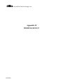
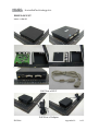
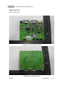
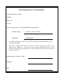
1
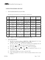
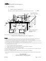
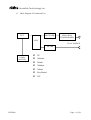
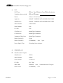
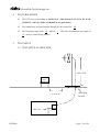
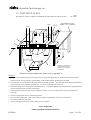
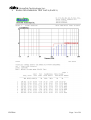
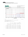
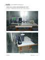
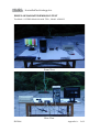
HomeTek Technology Inc. ADDRESS: No. 67-9, Shir Men Road, Tu Cheng City, Taipei Hsien, Taiwan PHONE : 886-2-22608375 FAX : 886-2-22748013 E - mail : [email protected] FCC TEST REPORT FOR APPLICANT ADDRESS EUT MODEL NO. : SMART CABLING & TRANSMISSION CORP. : 10F, No. 493, Chung-Cheng Rd., Hsin Tien City, Taipei 231, Taiwan, R. O. C. : Video to VGA Converter : AD001XXX NVLAP Lab Code:200331-0 Accredited by the National Voluntary Laboratory Accreditation Program for the specific scope of accreditation under Lab Code 200331-0 MEASUREMENT PROCEDURE USED FCC RULES AND CISPR 22-1997 AND FCC / ANSI C63.4-2003 PREPARED BY : HomeTek Technology Inc. No. 67-9, Shir Men Road, Tu Cheng City, Taipei Hsien. Taiwan Report # : FD5F006 Page : 1 of 28 HomeTek Technology Inc. TABLE OF CONTENTS .................................................................................................................................. 2 CERTIFICATION .................................................................................................................................................... 3 GENERAL INFORMATION ................................................................................................................................... 4 MODIFICATION LIST............................................................................................................................................ 6 CONDUCTED POWER LINE TEST ...................................................................................................................... 7 1 TEST INSTRUMENTS & FACILITIES ........................................................................................................ 7 2 TEST PROCEDURE ..................................................................................................................................... 7 3 TEST SETUP ................................................................................................................................................ 8 4 CONFIGURATION OF THE EUT................................................................................................................10 5 EUT OPERATING CONDITION .................................................................................................................15 6 LIMIT OF CONDUCTED POWER LINE EMISSION CLASS B...................................................................16 7 RESULT OF CONDUCTED POWER LINE TEST .......................................................................................16 8 CONDUCTED POWER LINE TEST DATA (PAGE 1).................................................................................17 9 CONDUCTED POWER LINE TEST DATA (PAGE 2).................................................................................18 10 CONDUCTED POWER LINE TEST DATA (PAGE 3).................................................................................19 11 CONDUCTED POWER LINE TEST DATA (PAGE 4).................................................................................20 RADIATED EMISSION TEST ...............................................................................................................................21 1 TEST INSTRUMENTS & FACILITIES .......................................................................................................21 2 TEST PROCEDURE ....................................................................................................................................22 3 TEST SETUP ...............................................................................................................................................22 4 CONFIGURATION OF THE EUT................................................................................................................24 5 EUT OPERATING CONDITION .................................................................................................................24 6 LIMIT OF RADIATED EMISSION CLASS B..............................................................................................24 7 RESULT OF RADIATED EMISSION TEST ................................................................................................25 8 RADIATED EMISSION TEST DATA (PAGE 1) .........................................................................................26 9 RADIATED EMISSION TEST DATA (PAGE 2) .........................................................................................27 SAMPLE OF FCC DOC LABEL 1.........................................................................................................................28 SAMPLE OF FCC DOC LABEL 2.........................................................................................................................28 APPENDIX A PHOTOS OF TEST CONFIGURATION APPENDIX B PHOTOS OF EUT FD5F006 Page : 2 of 28 HomeTek Technology Inc. GENERAL INFORMATION 1 APPLICANT : SMART CABLING & TRANSMISSION CORP. 2 ADDRESS : 10F, No. 493, Chung-Cheng Rd., Hsin Tien City, Taipei 231, Taiwan, R. O. C. 3 MANUFACTURER : SMART CABLING & TRANSMISSION CORP. 4 ADDRESS : 10F, No. 493, Chung-Cheng Rd., Hsin Tien City, Taipei 231, Taiwan, R. O. C. 5 DESCRIPTION OF EUT : EUT : Video to VGA Converter FCC ID : N/A Model Number : AD001XXX Serial # : N/A 5.1 The difference between series of models AD001XXX are as shown below: (1) The first “X” represents different system input. (2) The second “X” represent different accessory. (3) The third “X” represent different color. The PCB layout is similar. The worst case of EMC test data were shown in this test report. FD5F006 Page : 4 of 28 HomeTek Technology Inc. 6 FEATURES OF EUT : Please refer to user manual or product specification. 7 TEST MODE : The EUT were investigated with two resolution and three I/O port modes shown as below : (1) Composite Video Mode (1024 x 768 75Hz); (2) Composite Video Mode (800 x 600 75Hz); (3) S-Video Mode (1024 x 768 75Hz); (4) S-Video Mode (800 x 600 75Hz); (5) VGA Mode (1024 x 768 75Hz) The final test data were shown in this test report. FD5F006 Page : 5 of 28 HomeTek Technology Inc. MODIFICATION LIST THE FOLLOWING ACCESSORIES WERE ADDED TO THE EUT DURING TESTING : NO MODIFICATION BY HOMETEK TECHNOLOGY INC. FD5F006 Page : 6 of 28 HomeTek Technology Inc. CONDUCTED POWER LINE TEST 1 TEST INSTRUMENTS & FACILITIES The following test Instruments was used during the conducted test : Item Instruments/ Facilities Specification 1 EMI Receiver 9KHz ~ 30MHz 2 3 50Ω/50uH/100A LISN (for EUT) 150KHz ~ 30MHz 50Ω/50uH/10A LISN (for Support Unit) 9KHz ~ 30MHz Model # S/N Manufacturer ROHDE & SCHWARZ SCHWARZ BECK ROHDE & SCHWARZ Date Of Cal. ESHS 30 FEB/2006 844827/007 NNLK 8121 OCT/2005 8121370 ESH3-Z5 MAR/2006 846128/007 4 Terminator 50Ω N/A N/A NOV/2005 5 Attenuation 50Ω/10dB Mini-Circuit NAT-10 AT-002 JUL/2005 6 Cable 5.4m SUHNER RG-223 CON2-002 AUG/2005 7 ESXS-K1 (software) Version 2.03b 9KHz ~ 30MHz ROHDE & SCHWARZ 1082.9678.02 840.913/246 N/A Note : 2 FD5F006 Items 1 ~ 6 were calibrated within period of 1 year. TEST PROCEDURE 2.1 The EUT was tested according to ANSI C63.4 – 2003 Section 5.2, 7.1, 7.2 & CISPR 22 - 1997 & C18-01-12 (HomeTek test procedure). 2.2 The EUT was placed 0.4 meter from the conducting wall of shielding room and kept at least 0.8 meter from any other grounded conducting surface. 2.3 The frequency range form 0.15 MHz to 2.4 The LISN used was 50 Ohm / ANSI C63.4 - 2003. 2.5 All the support peripherals are connect to the other LISN. 2.6 Cables and peripherals were moved to find the maximum emission levels for each frequency. 30 MHz was investigated. 50 uHenry as specified by Section 4.1.2 of Page : 7 of 28 HomeTek Technology Inc. 3 TEST SETUP 3.1 Typical : Setup Of Conducted Test ELECTRICAL AND ELECTRONIC EQUIPMENT IN THE RANGE OF 9kHz TO 40 GHz 10cm EUT 10cm ANSI C63.4-2003 NONCONOUCTIVE TABLE 1.5 x 1 METER 5 5 6 ∞ 80 cm To GROUND PLANE 4 7 ∞ ∞ + LISN 3.3 3 ∞ 1 3.1 2 3.3 40cm LISN + CONDUCTING GROUND PLANE EXTENDS AT LEAST 0.5m BEYOND EUT SYSTEM FOOTPRINT BONDED TO GROUND PLANE +LISNs may have to be moved to the side to meet 3.3 below. (Details for setup configuration, please refer to appendix A.) LEGEND: 1. Interconnecting cables that hang closer than 40 cm to the ground plane shall be folded back and forth forming a bundle 30 to 40 cm long, hanging approximately in the middle between ground plane and table. 2. I/O cables that are connected to a peripheral shall be bundled in center. The end of the cable may be terminated if required using correct terminating impedance. The total length shall not exceed 1m. 3. EUT connected to one LISN. Unused LISN connectors shall be terminated in 50 Ω. LISN can be placed on top of, or immediately beneath, ground plane. 3.1 All other equipment powered from second LISN. 3.2 Multiple outlet strip can be used for multiple power cords of non-EUT equipment. 3.3 LISN at least 80 cm from nearest part of EUT chassis. 4. Cables of hand-operated devices, such as keyboards, mouses, etc., have to be placed as close as possible to the host. 5. Non-EUT components being tested. 6. Rear of EUT, including peripherals, shall be all aligned and flush with rear of tabletop. 7. Rear of tabletop shall be 40 cm removed from a vertical conducting plane that is bonded to the floor ground plane (see 5.2). Test Configuration Tabletop Equipment Conducted Emission FD5F006 Page : 8 of 28 HomeTek Technology Inc. 3.2 Block Diagram Of Conducted Test RECEIVER EUT ISOLATION TRANSFORMER LISN TO AC SOURCE FILTER LOAD (ACTIVE) FD5F006 ; PC ; Monitor ; Printer ; Modem ; Mouse ; Key Board ; DV Page : 9 of 28 HomeTek Technology Inc. 4 CONFIGURATION OF THE EUT The EUT was configured according to ANSI C63.4 - 2003 & CISPR 22 - 1997. All I/O ports were connected to the appropriate peripherals. All peripherals and cables are listed below (including internal device) : AC SOURCE LISN c d Monitor PC e f EUT DV Printer Modem Keyboard (PSII) Mouse (PSII) c, d VGA Cable e S-Video Cable f Video Cable Figure 1 FD5F006 Page : 10 of 28 HomeTek Technology Inc. 4.1 EUT EUT Type : Proto Type ;Engineer Type Mass Production Condition when received : ;Good Damage : Device : Video to VGA Converter Applicant : SMART CABLING & TRANSMISSION CORP. Manufacturer : SMART CABLING & TRANSMISSION CORP. Model Number : AD001XXX Serial Number : N/A FCC ID : N/A VGA Port x 2 : Metal Type Connector S-Video Port : Metal Type Connector Composite Video Port : Metal Type Connector Power Cord (AC) : 2 pin Power Cord (DC) : Un-Shielded, Power Supply Type : Switching Power Adapter 1.8 m, 2 pin 4.2 PERIPHERALS ; FD5F006 Host Personal Computer Manufacturer : DELL Model Number : DHM Serial Number : GCZP71S FCC ID : FCC DoC Data Cable : Shielded, Power Cord : Un-Shielded, 1.8 m, Connected to the VGA port 1.8 m Page : 11 of 28 HomeTek Technology Inc. ; ; ; FD5F006 Monitor Manufacturer : SAMSUNG Model Number : GH19BS Serial Number : GH19H4JW103538B FCC ID : FCC DoC Data Cable : Shielded, Power Cord : Un-Shielded, 1.8 m, Connected to the VGA port 1.8 m Printer Manufacturer : HP Model Number : DJ400 Serial Number : MY77T1D0DD FCC ID : B94C2642X Data Cable : Shielded, Power Cord & Adaptor : Un-Shielded, 1.5 m, Connected to the Printer port 1.8 m Modem Manufacturer : ACEEX Model Number : 1414 Serial Number : 9013522 FCC ID : IFAXDM1414 Data Cable : Shielded, Power Cord & Adaptor : Un-Shielded, 1.5 m, Connected to the COM port 1.8 m Page : 12 of 28 HomeTek Technology Inc. ; ; ; FD5F006 Mouse (PSII) Manufacturer : HP Model Number : M-S69 Serial Number : 334684-002 FCC ID : FCC DoC Data Cable : Shielded, Power Cord : N/A 1.8 m, Connected to the PSII port 1.5 m, Connected to the PSII port KeyBoard (PSII) Manufacturer : DELL Model Number : SK-8110 Serial Number : 31U-0512 FCC ID : FCC DoC Data Cable : Shielded, Power Cord : N/A DV Manufacturer : SONY Model Number : DCR-PC110 Serial Number : 1158142 FCC ID : FCC DoC Data Cable 1 : Shielded, 1.6 m, Connected to the S-Video port Data Cable 2 : Shielded, 1.6 m, Connected to the Composite Video port Power Cord : Un-Shielded, 1.8 m Page : 13 of 28 HomeTek Technology Inc. ; Power Adapter Manufacturer : Atech Model Number : RHF-050120-1C Serial Number : N/A FCC ID : N/A Data Cable : N/A Power Cord (DC) : Un-Shielded, 1.8 m 4.3 REMARK : N/A FD5F006 Page : 14 of 28 HomeTek Technology Inc. 5 EUT OPERATING CONDITION 5.1 The oscillator frequencies of the EUT are 12 MHz and 14.318 MHz. 5.2 Configure the EUT according to the ANSI C63.4 - 2003 & CISPR 22 - 1997. 5.3 The test configuration included PC, monitor, keyboard, mouse, printer, modem and DV. 5.4 Turn on all the power of EUT and peripheral. 5.5 During the test, DV sends color bar to the EUT through each input port individually. Monitor display color bar. (For Composite Video 1024 x 768 75Hz, Composite Video 800 x 600 75Hz, S-Video 1024 x 768 75Hz, S-Video 800 x 600 75Hz). 5.6 During the test, the PC sends “H” patterns the EUT through each input port individually. Monitor display “H” character. (For VGA 1024 x 768 75Hz). FD5F006 5.7 Measure the maximum emission noise. 5.8 The photos of conducted test configuration, please refer to appendix A. Page : 15 of 28 HomeTek Technology Inc. 6 LIMIT OF CONDUCTED POWER LINE EMISSION CLASS B 6.1 7 FD5F006 Frequency Range Quasi Peak Average 0.15 ~ 0.5 MHz 66 - 56 dBuV 56 - 46 dBuV 0.5 ~ 5 MHz 56 dBuV 46 dBuV 5 ~ 30 MHz 60 dBuV 50 dBuV In the above table, the tighter limit applies at the band edges. RESULT OF CONDUCTED POWER LINE TEST 7.1 The frequency range from 0.15 MHz to readings are quasi-peak values and average. 7.2 IF bandwidth : 9 kHz, Meas Time : 7.3 Temperature : 28 ℃, Humidity : 7.4 Deviations from the test standards and rules : None 7.5 The conducted test result were gained by following procedures : Level = Reading Level + Insertion Loss of LISN + Cable Loss (All calculation were done by ESHS30 EMI test receiver.) 7.6 Result : 1 30 MHz was investigated. All sec. 62 % RH. PASSED Page : 16 of 28 HomeTek Technology Inc. 8 FD5F006 CONDUCTED POWER LINE TEST DATA (PAGE 1) Page : 17 of 28 HomeTek Technology Inc. 9 FD5F006 CONDUCTED POWER LINE TEST DATA (PAGE 2) Page : 18 of 28 HomeTek Technology Inc. 10 FD5F006 CONDUCTED POWER LINE TEST DATA (PAGE 3) Page : 19 of 28 HomeTek Technology Inc. 11 FD5F006 CONDUCTED POWER LINE TEST DATA (PAGE 4) Page : 20 of 28 HomeTek Technology Inc. RADIATED EMISSION TEST 1 TEST INSTRUMENTS & FACILITIES The following test Instruments was used during the radiated emission test : Item Instruments /facilities Specification 1 OPEN AREA TEST SITE ; OATS 3 2 EMI TEST RECEIVER 20Hz ~ 26.5GHz ROHDE & SCHWARZ ESMI 845442/006 FEB/2006 3 PREAMPLIFIER 9KHz ~ 3000MHz ADVANTEST BB525C 90081001 OCT/2005 4 ANTENNA (BI-LOG) 25MHz ~ 2GHz SCHAFFNER CBL6112B S/N : 2614 JUN/2006 5 Attenuation 50Ω/6dB JYE BAO FAT-N (M-F) 001 JUL/2005 6 Cable 10m SUHNER RG214/U OS3-003 DEC/2005 7 Cable 14m BELDEN 9913 OS3-001 DEC/2005 8 EMI 32 (software) N/A AUDIX 19991013-0923 N/A Note : FD5F006 Manufacturer Model # / S/N# Date of Cal. JUL/2005 Items 1 ~ 7 were calibrated within period of 1 year. Page : 21 of 28 HomeTek Technology Inc. 2 3 TEST PROCEDURE 2.1 The EUT was test according to ANSI C63.4 – 2003 Section 5.4, 5.5, 8.1, 8.2, 8.3 & CISPR 22 - 1997 & C18-01-11 (HomeTek test procedure). 2.2 The radiated test was performed at HomeTek Lab’s Open Site III. 2.3 The frequency range from 30 MHz to 10 meters, with a BI-log antenna. 1 GHz, the measurement were made at TEST SETUP 3.1 TEST SETUP OF OPEN SITE. 1 M to 4 M EUT 3 or 10 M GROUND PLANE Receiver FD5F006 Page : 22 of 28 HomeTek Technology Inc. 3.2 TEST SETUP OF EUT ELECTRICAL AND ELECTRONIC EQUIPMENT IN THE RANGE OF 9kHz TO 40 GHz 10cm ANSI C63.4-2003 NONCONOUCTIVE TABLE 1.5 x 1 METER EUT 10cm 5 5 6 7 80 cm To GROUND PLANE ∞ 8 ∞ 4 ∞ 1 3 2 40cm 8 CONDUCTING GROUND PLANE EXTENDS 0.5m BEYOND EUT SYSTEM FOOTPRINT (Details for setup configuration, please refer to appendix A.) LEGEND: 1. Interconnecting cables that hang closer than 40 cm to the ground plane shall be folded back and forth forming a bundle 30 to 40 cm long, hanging approximately in the middle between ground plane and table. 2. I/O cables that are connected to a peripheral shall be bundled in center. The end of the cable may be terminated if required using correct terminating impedance. The total length shall not exceed 1m. 3. If LISNs are kept in the test setup for radiated emissions, it is preferred that they be installed under the ground plane with the receptacle flush with the ground plane. 4. Cables of hand-operated devices, such as keyboards, mouses, etc., have to be placed as close as possible to the controller. 5. Non-EUT components of EUT system being tested. 6. The rear of all components of the system under test shall be located flush with the rear of the table. 7. No vertical conducting wall used. 8. Power cords drape to the floor and are routed over to receptacle. Test Configuration Tabletop Equipment Radiated Emission FD5F006 Page : 23 of 28 HomeTek Technology Inc. 4 CONFIGURATION OF THE EUT Same as “Conducted Power Line test”, section 4 5 6 EUT OPERATING CONDITION 5.1 Same as “Conducted Power Line test”, section 5 5.2 The radiated emission in the frequency range from 30 MHz - 1000 MHz was test in a horizontal and vertical polarization at HomeTek Lab’s open site III. 5.3 The photos of radiated test configuration, please refer to appendix A. LIMIT OF RADIATED EMISSION CLASS B CISPR 22 FD5F006 Frequency (MHz) Measurement Distance Limit (dBuV/m) 30 - 230 10 (M) 30 230 - 1000 10 (M) 37 6.1 The tighter limit shall apply at the edge between two frequency bands. 6.2 Measurement distance in meters between the measuring instrument antenna and the closed point of any part of the EUT or peripherals. Page : 24 of 28 HomeTek Technology Inc. 7 RESULT OF RADIATED EMISSION TEST 7.1 The frequency range from 30 MHz to 1 GHz was investigated. 7.2 All readings below or equal 1 GHz are quasi-peak or peak values with resolution bandwidth of 120 KHz. 7.3 All readings above 1 GHz are average or peak values with resolution bandwidth of 1 MHz 7.4 The measurements were made at 7.5 Temperature : 7.6 Deviation form the test standards and rules : None 7.7 The radiation emission result were gained by the following method : 31 ℃, Humidity : 10 meters of HomeTek Lab’s open site III. 58 % RH. Level = Reading Level + Probe Factor (Antenna Factor) + Cable Loss – Preamp Factor Over Limit = Level – Limit Line 7.8 The radiated mission test was passed at minimum margin : Vertical 198.03 MHz/ 28.14 dBuV/m, Antenna Height 1.4 Meter, Turn Table 180 degree, The Mode: AD001H ,Model : S-Video Mode (800 x 600 75Hz) . 7.9 FD5F006 Result : PASSED Page : 25 of 28 8 FD5F006 HomeTek Technology Inc. RADIATED EMISSION TEST DATA (PAGE 1) Page : 26 of 28 9 FD5F006 HomeTek Technology Inc. RADIATED EMISSION TEST DATA (PAGE 2) Page : 27 of 28 HomeTek Technology Inc. SAMPLE OF FCC DoC LABEL 1 This device complies with part 15 of the FCC Rules. Operation is subject to the following two conditions: (1) This device may not cause harmful interference. And (2) this device must accept any interference received, including interference that may cause undesired operation. SAMPLE OF FCC DoC LABEL 2 Trade Name Model Number FD5F006 Page : 28 of 28 HomeTek Technology Inc. Appendix A PHOTOS OF TEST CONFIGURATION FD5F006 HomeTek Technology Inc. PHOTO OF CONDUCTED POWER LINE TEST Test Mode : S-VIDEO Mode 1024 x768 75Hz , Model : AD001H Front View Rear View FD5F006 Appendix A : 1 of 2 HomeTek Technology Inc. PHOTO OF RADIATED EMISSION TEST Test Mode : S-VIDEO Mode 800 x600 75Hz , Model : AD001H Front View Rear View FD5F006 Appendix A : 2 of 2 HomeTek Technology Inc. Appendix B PHOTOS OF EUT FD5F006 HomeTek Technology Inc. PHOTO OF EUT Model : AD001H Full View of EUT Full View of Adaptor FD5F006 Appendix B : 1 of 2 HomeTek Technology Inc. PHOTO OF EUT Model : AD001XXX Component Side of Main Board Solder Side of Main Board FD5F006 Appendix B : 2 of 2 Declaration of Conformity Responsible Party Name : Address : Phone No : Fax No : Declares under our sole responsibility that the product Product Name : Video to VGA Converter Model No. : AD001XXX to which this declaration relates is in conformity with the following standards or other normative documents This device complies with Part 15 of the FCC Rules. Operation is subject to the following two conditions : (1) this device may not cause harmful interference, and (2) this device must accept any interference received, including interference that may cause undesired operation. Representative Person’s Name : Signature : Date :