1
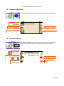
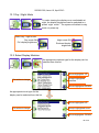
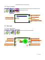
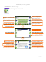
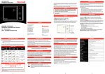
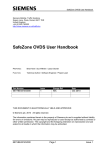
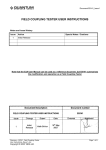
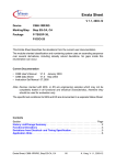
562300-000, Issue1.0, April 2013
PME 300
PME300+
Machine Envelope Controller
Operators Manual
This guide describes operation of the
PROLEC PME ENVELOPE SAFETY SYSTEM FOR CONSTRUCTION PLANT
Model covered :
PART No.
PME300
PME300+
MODEL Ref
PME300 - MEC SYSTEM
PME300+ - MEC SYSTEM
Prolec supports a nationwide network of fully trained service engineers. Warranty claims,
service work, technical information and spare parts are available by contacting :
Prolec Ltd
25 Benson Road
Nuffield Industrial Estate
Poole Dorset BH17 0GB
Telephone
Fax
E-mail
+44 (0) 1202 681190
+44 (0) 1202 677909
[email protected]
.
THIS ENVELOPE SAFETY SYSTEM IS NOT SUITABLE FOR USE IN EXPLOSIVE
ATMOSPHERES. ADJUSTMENT BY UNAUTHORISED PERSONS WILL INVALIDATE
ANY WARRANTY OR CERTIFICATION SUPPLIED. IF A PROBLEM ARISES WHICH
CANNOT BE RECTIFIED USING THIS GUIDE, AUTHORISED SERVICE SHOULD BE
SOUGHT.
Any alterations or modifications to machine components which affect this system and any
system component failure must be reported to Prolec Ltd or via the machine convertor/
service agreement holder. This manual must be kept with the product and be passed on
to any subsequent user of the product.
Whilst every effort has been made to ensure the accuracy of the information supplied in
this manual, Prolec Ltd cannot be held responsible for any errors or omissions.
Manufacturers original instructions.
Table of contents
1
Use of this Document
7
2
Notices
7
3
System Identification
8
4
Operating and Restriction Situation Recommendations
9
5
Operating Instructions
10
5.1 Power Up
10
5.2 Using the Display
11
5.3 User Login
12
5.4 User Logout
13
6
Top Menu
13
7
Envelope Monitoring
14
7.1 Limits Menu
15
7.1.1
Angular Slew Restriction - Using current Slew Angle
16
PME300+ only
7.1.2
Virtual Wall Restriction - using virtual wall
18
7.1.3
Twin Virtual Wall Restriction - using twin virtual wall
20
7.1.4
Multipoint Wall Restriction - using Multipoint Wall
22
7.1.5
Machine Envelope Controller (MEC) - Slew / Wall
25
7.2 Limit Control Override
26
7.2.1
Soft Override
26
7.2.2
Master Override Key Switch
26
Table of contents (continued)
8
System Messages
27
8.1 On Screen Messages
27
8.2 LED and Internal Alarm Warnings
27
9
Daily checks
28
10
Repair
28
11
Test / Diagnostics
29
11.1 Relay Function Test
29
11.2 Slew Angle
30
11.3 Beacon, LED Alarm Function Test
30
12
System Information
31
13
Display Settings
31
13.1 Day / Night Mode
32
13.2 Select Display Machine
32
13.3 Select Language
33
User Login
33
16.1 User Login Setup
33
16.2 Add New User to Login
34
16.3 Edit User Details
35
16.4 Select User to Delete
36
16.5 Edit User Access Code
36
16.6 Enable / Disable Users
37
16
Table of contents (continued)
14
User Login
33
14.1 User Login Setup
33
14.2 Add New User to Login
34
14.3 Edit User Details
35
14.4 Select User to Delete
36
14.5 Edit User Access Code
36
14.6 Enable / Disable Users
37
15
Taking Product out of Operation
37
16
Service and Repair
37
16.1 Maintenance Review
17
Definitions / Glossary
38
562300-000, Issue1.0, April 2013
1
Use of this Document
This user guide is intended for persons familiar with the use of construction plant undertaking lifting operations.
WARNING denotes information about particular risks which may be
generated by certain applications, by using certain fittings, and
about additional protective measures which are necessary for such
applications.
Caution, care, risk situation
HAZARD Actions that can lead to serious injury or death
2
Notices
Adjustment by unauthorised persons will invalidate any warranty or certification supplied.
If an error condition is displayed which cannot be rectified using this guide, halt any operation, seek authorised service immediately and do not continue operation until the fault
7 of 40
562300-000, Issue1.0, April 2013
3
System Identification
The PME system provides an envelope safety function
This safety function is achieved through real time monitoring some or all
of the machine’s moving parts (booms, other articulations, turret etc)
and its environment (ground pitch and inclination) and actively determining the safety of the current operation where appropriate limits have
been set.
Machine envelope controllers (MEC) prevent movements that
would bring parts of the machine into hazardous areas.
During operation the indicators shown here on the left are displayed on
the screen to clearly identify the function supported by your PME 300.
Functions may not be available i.e. when envelope monitoring is
switched off, if this is the case a cross will be painted over the function
icon.
PME300 and PME300+ are NOT height limiting devices
8 of 40
562300-000, Issue1.0, April 2013
4
Operating and Hazard Situation Recommendations
Operating Recommendations
When using envelope monitoring:
When setting a slew restriction , make sure any implement attached is in its least
favourable position
Check for correct operation once the restriction or restriction have been set
Reduce operating speed
Reset slew restriction if the machine
Do not move the equipment quickly when close to a restriction
Do not operate the machine in a reckless manor
Do not travel with a restriction set
Reset the slew restriction if the machine is relocated
Hazard Situation Recommendations
In a limit hazard state:
Return the control levers to neutral once a limit has been reached if appropriate
Operate the machine at a slow speed
4.1 MEC Override
The system can optionally be fitted with a key operated master override
switch. Turning the switch to the override position will allow normal operation
of any of the hydraulic services regardless of safety status. When the unit is
in override the external alarms will stay active, and the beacon (if fitted) will
indicate that the machine is overridden, the red LED will flash and an ‘In
Override’ message will appear on the display.
The override key switch should only be used if the safety system is not operational due to a fault and the machine needs to be moved due to its location
presenting a hazard.
The override status shall be recorded in the system data log. To access the override key
switch, the seal must be broken.
9 of 40
562300-000, Issue1.0, April 2013
5 Operating Instructions
5.1 Power Up
The PME system automatically powers up when the machines ignition is switched on.
The in-cab unit incorporates a 4.3” high resolution LCD display and is controlled with
three buttons at each side. Three status LEDs and an internal alarm provide further information.
The system will perform a self check at start up:
1.
All LEDs will flash, the internal display alarm and the external alarm will sound.
2.
The RED LED will light indicating the system is starting and performing a self test.
3.
Once the self test is complete, the GREEN LED will light and the system will become active. A safety warming message is displayed, pressing any button activates
slew limitation Mode. Any previous limits set will be enabled. The system is now
ready for use.
4.
The system can be configured to require a user login - if this is enabled, see section
5.3.
If the RED LED remains lit, a fault has been detected, halt any operation, seek authorised
service immediately and do not continue operation until the fault has been remedied.
The display is secured to the machine using a flexible ball mounting allowing easy adjustment for personal viewing preference.
10 of 40
562300-000, Issue1.0, April 2013
5.2 Using the Display
The display is operated by using the buttons adjacent to a function icon. The buttons can
open a sub menu, turn a function ON or OFF, set a value, toggle through multiple
screens, no one button has a single function. The button icon will turn black/purple when
the button has been activated. PME300 screen shown below. Note that the side view of
the machine shown in PME300+ is fixed and does not follow the movement of the machine.
Multifunction buttons:
The action of the button is
indicated by the adjacent
icon.
A secondary symbol can appear in the top left corner of an icon, these mean :
The plus symbol indicates a sub menu will be opened if selected.
The cycle symbol indicates that multiple features are available.
The on / off symbols indicate if a feature is ON or OFF. Red is ON and grey is OFF.
Help is available for each button. To access the
help, push and hold the button for three seconds.
The help screen can be cleared by pressing any of
the six buttons. PME is still active when displaying
help messages, if the Lifting Mode is active and or a
height limit is set any alarm or warning condition will
be indicated.
11 of 40
562300-000, Issue1.0, April 2013
5.3 User Login
If PME has been configured to work with the built-in user list, the system will prompt for a
user login pass code. Select the user name required and the login code screen will appear.
Moves highlighter UP
About Login
Select highlighted name
to open Enter Login
Code screen below
Moves highlighter DOWN
Using the arrow buttons to enter a valid pass code. The previous pass code digits will be
replaced with a star as the code is entered. Press the TICK button to confirm the login
pass code. If a valid pass code is entered the system will commence normal operation.
Cancel without
change
Cancel without change
Accept displayed
value
Moves highlighter UP
Accept highlighted duty
Moves highlighter DOWN
If an incorrect login code is entered, a failure screen will be
displayed. Press the TICK button to return to the Select
User screen.
12 of 40
562300-000, Issue1.0, April 2013
5.4 User Logout
If a user is logged in as the current user, they can select the logout screen by holding an
exit key down for three seconds.
Cancel to stay
logged in
Confirm logout
Once logout has been confirmed the login screen will be automatically displayed.
Press the CROSS button to stay logged in, the screen will return to that previously
shown.
6
Top Menu
The Top Menu screen allows access to all the system functions. To reveal the icons, if
hidden, press any button. To return to the Top Menu from a sub menu press the EXIT
button until the Top Menu is displayed.
Top Menu button functions:
Limits menu
Test / Diagnostics
Hide icons
Menu level indicator
Limits Menu
Test Diagnostics
Hide icons
To hide the icons when at the Top Menu, press the EXIT
button once more.
PME300 screen shown here.
13 of 40
562300-000, Issue1.0, April 2013
7
Envelope Monitoring
PME300 and PME300+ is configured for Machine Envelope Control (MEC)
only. MEC will warn and prevent equipment motion. MEC is achieved by interacting with the machines hydraulics, this allows motion to be cut to any section
of equipment that has reached a restriction but allow other sections to operate
unhindered unless they too reach the set restriction .
PME300 monitors the slew angle of the machine but is unaware of any articulation or implement fitted, therefore make sure any articulation or implement attached is in its least
favourable position.
PME300+ monitors the slew angle, the furthest part of the machine and the counterweight when used with a virtual wall type restriction but is unaware of any implement fitted therefore make sure any implement attached is in its least favourable position.
Slew Limiting
Exit to previous screen
MEC
OFF: when operating with an inactive limit the indicator will have a cross painted
on it.
ON: when operating with an active limit the indicator will not have a painted on
cross on it.
Care should be taken to test that the limit is set correctly.
Observe the operational limitations given in section 4.
14 of 40
562300-000, Issue1.0, April 2013
7.1 Limits Menu
Slew restriction can be set by manually moving the machine to
the desired limit. PME300+ Slew limits screen shown here.
Switches slew monitoring
ON
and OFF
Press this button
to start the setup
procedure
PME300+ Only
Current hazard zone
shown if a slew limit is
ON.
Exit to previous menu
Using the Slew Limits Menu, the Slew limit can be
switched ON and OFF (a Confirm Operation screen will
be displayed). The type of slew restriction can be selected (PME300+ only) and is be set by moving the machine.
With the slew limit ON:
The Green area indicates the safe zone
The Hatched area indicates the hazard zone
The type of slew restriction cannot
be altered if a limit is currently
ON. The warning message must
be acknowledged.
If altering the type of slew
Restriction (PME300+ only), the
current limit will be lost.
If the slew limit was not
successfully set then a warning
message which must be acknowledged will be displayed.
15 of 40
562300-000, Issue1.0, April 2013
7.1.1 Angular Slew Restriction- using Current Slew Angle
Select angular slew restriction, PME 300 is supports
angular slew only. PME300 Slew limits screen
shown here.
Icon appears in 300+ only
Press this button to start
the setup procedure
Step One
Step by step instructional banner
Position articulations and any implement attached
to the least favourable position.
Step two
Move to the left slew limit, press any button
to set the left limit. A marker will be placed
to indicate its position.
Continued on next page
16 of 40
562300-000, Issue1.0, April 2013
Step three
Move to the right slew limit, press any button
to set the left limit. Another marker will be placed
here.
Slew left restriction
marker
Step four
Press any button to complete.
The hatched hazard zone will be shown on the
main screen.
Check the limits are working as required.
Safe Directional indicators. The left and
right arrows indicate if it is safe GREEN,
or unsafe RED to slew in that direction
Once slew limits are set, the internal alarm will sound and the RED
LED will light if the equipment exceeds the either limit. Always
check that the slew limit activates at the set points. The restriction cannot be
deactivated if in the alarm state. Do not travel. Observe the operational limitations given in section 4.
17 of 40
562300-000, Issue1.0, April 2013
7.1.2 Virtual Wall Restriction- using Virtual Wall
Select single vertical wall restriction (PME300+
only), follow the on screen instructions.
Set to Virtual Wall
Press this button to start
the setup procedure
Step One
Step by step instructional banner
Move the dipper to one end of the virtual wall,
press any button to set the limit. A marker will be
placed here.
Step two
Virtual wall marker
Move the dipper to the other end of the virtual
wall, press any button to set the limit.
Continued on next page
18 of 40
562300-000, Issue1.0, April 2013
Step three
Move the equipment away from the limit and press
any button to complete.
The hatched hazard zone will be shown on the
main screen.
Check the limit is working as required.
Safe Directional indicators. The triangles
indicate if it is safe GREEN, or unsafe RED
to movement a particular articulation.
Safe Directional indicators. The left and
right arrows indicate if it is safe GREEN, or
unsafe RED to slew in that direction.
Once slew limits are set, the internal alarm will sound and the RED
LED will light if the equipment exceeds the either limit. Always
check that the slew limit activates at the set points. The restriction cannot be
deactivated if in the alarm state. Do not travel. Observe the operational limitations given in section 4.
19 of 40
562300-000, Issue1.0, April 2013
7.1.3 Twin Virtual Wall Restriction- using Twin Virtual Walls
Select twin vertical wall restriction (PME300+ only),
follow the on screen instructions.
Set to twin Virtual Wall
Press this button to start
the setup procedure
Step One
Step by step instructional banner
Move the end of the dipper to one end of the
FIRST virtual wall, press any button. A marker will
be placed here.
Virtual wall marker
Step two
Move the end of the dipper to the other end of the
FIRST virtual wall, press any button. A marker will
be placed here.
Step three
Move the end of the dipper to one end of the SECOND virtual wall, press any button. A marker will
be placed here.
20 of 40
Continued on next page
562300-000, Issue1.0, April 2013
Step four
Move the dipper to the other end of the SECOND
virtual wall, press any button. A marker will be
placed here.
Step four
Move the equipment away from the limit and press
any button to complete.
The hatched hazard zones will be shown on the
main screen.
Check the limits are working as required.
Safe Directional indicators. The triangles
indicate if it is safe GREEN, or unsafe RED
to movement a particular articulation.
Safe Directional indicators. The
left and right arrows indicate if it
is safe GREEN, or unsafe RED
to slew in that direction.
Once slew limits are set, the internal alarm will sound and the RED
LED will light if the equipment exceeds the either limit. Always
check that the slew limit activates at the set points. The limit cannot be deactivated if in the alarm state. Do not travel. Observe the operational limitations given in section 4.
21 of 40
562300-000, Issue1.0, April 2013
7.1.4 Multipoint Envelope Restriction- using Multipoint Wall
Select multipoint envelope restriction (PME300+
only), follow the on screen instructions.
Set to multipoint
Any number of points can be used, four are shown
in the example below.
Press this button to start
the setup procedure
Step by step instructional banner
Step One
Move the end of the dipper to the FIRST point of
the box, press any button. A marker will be placed
here.
Step two
Virtual wall marker
Move the end of the dipper
to the SECOND point of the box, press any button.
A marker will be placed here.
Step three
Move the end of the dipper to the THIRD point of
the box, press any button. A marker will be placed
here.
22 of 40
562300-000, Issue1.0, April 2013
Step four
Confirm if another position is needed, the tick is
selected in this example
Step five
Move the end of the dipper to the FORTH point of
the box, press any button. A marker will be placed
here.
Step six
Confirm if another position is needed, the cross is
selected in this example
Step seven
Move the end of the dipper the equipment away
from the limit and press any button to complete.
Continued on next page
23 of 40
562300-000, Issue1.0, April 2013
7.1.4 Multipoint Envelope Restriction- using Multipoint Wall continued
The hatched hazard zones will be shown on the
main screen.
Check the limits are working as required.
Safe Directional indicators. The triangles
indicate if it is safe GREEN, or unsafe RED
to movement a particular articulation.
Safe Directional indicators. The
left and right arrows indicate if it
is safe GREEN, or unsafe RED
to slew in that direction.
Once slew limits are set, the internal alarm will sound and the RED
LED will light if the equipment exceeds the either limit. Always
check that the slew restrictions activates at the set points. The restriction
cannot be deactivated if in the alarm state. Do not travel. Observe the
operational limitations given in section 4.
24 of 40
562300-000, Issue1.0, April 2013
7.1.5 Machine Envelope Controller (MEC) - Slew / Wall
If the equipment enters the approach limit* an
‘Approaching slew limit’ message will appear, the
internal alarm will beep and the amber LED will be
lit.
MEI systems will cut motion to any section of
equipment that has
reached a limit but allow
other sections to operate
unhindered unless they too
reach the set limit.
If the equipment reaches the limit, the appropriate
motion will be controlled.
The safe directional indicators will be red.
Unsafe motion is indicated by RED
arrows/triangles, safe motion is indicated
by GREEN arrows/ triangles
The red LED will flash
The internal alarm will sound
A warning message will be displayed
*The approach limit is configurable at point of calibration, check system operation before
commencing work.
See sections 7.1 for hydraulic override details.
Once slew limits are set, the internal alarm will sound and the RED
LED will light if the equipment exceeds the either limit. Always
check that the slew limit activates at the set points. The restriction cannot be
deactivated if in the alarm state. Do not travel. Observe the operational limitations given in section 4.
25 of 40
562300-000, Issue1.0, April 2013
7.2 Limit Control Override
7.2.1 Soft Override
After three seconds a soft override button will appear in the right hand middle
icon if the Top Menu screen is selected. If the soft override button is pressed,
the machine hydraulics will be re-enabled. However, the internal alarm will
stay active, the red LED will flash, the beacon (if fitted) will switch off and an In
Override message will appear on the display. Once the alarm condition has
been corrected the RCC will automatically clear the override request and revert to normal
operation.
Soft override
7.2.2 Master Override key Switch
The system can optionally be fitted with a key operated
Master override switch. Turning the switch to the override
position will allow normal operation of any of the hydraulic
services regardless of safety status. When the unit is in override the internal
alarm will stay active, and the beacon (if fitted) will indicate that the machine
is overridden, the red LED will flash and an In Override message will appear
on the display. See section 4.1 for further details.
Once slew limits are set, the internal alarm will sound and the RED
LED will light if the equipment exceeds the either limit. Always
check that the slew limit activates at the set points. The limit cannot be deactivated if in the alarm state. Do not travel. Observe the operational limitations given in section 4.
26 of 40
562300-000, Issue1.0, April 2013
8
System Messages
8.1 On Screen Messages
Approaching Slew limit
Slew Limit exceeded
Equipment within *10 degrees of set limit
Equipment has reached/exceeded set limit
*The approach limit is configurable at point of calibration, check system operation before
commencing work.
PME continuously monitors the presence and condition of the safety controller and sensors. If the safety controller or any sensor fails an error message box will appear at the
bottom of the display. In the event of a failure, the cab mounted beacon (if fitted) will indicate that the system is NOT active, the display red LED will flash and the internal and external alarms will sound.
8.2 LED and Internal Alarm Warnings
The table below shows the state of the three LEDs on the display and the internal alarm
with respect to system status.
LED and Internal Alarm status
System status
Off
Start up, Power Down
Operational: System OK, no warnings, hazards, or errors
1 Hz
Warning: Approach to envelope limit
Continuous
Hazard; breach of an envelope limit
Maintenance: Engineering access active
8 Hz
Error: PME hardware/software error, or sensor failure
27 of 40
562300-000, Issue1.0, April 2013
9
Daily Checks
Display - check for damage and correct operational
Safety Controller - check for damage and correct operational
Sensors and sensor cabling - check for damage
Connectors - check for damage
Alarm / beacon functionality
See section 11.1 for test / diagnosis features.
If an issue is discovered which cannot be rectified using this guide, halt any operation,
seek authorised service immediately and do not continue operation until the fault has
been remedied.
10 Repair
Once a repair has been carried out and tested, the following must be checked:
Required Checks
Section
Slew Angle Check
11.2
Relay Check
11.1
Alarm, LED and Beacon Check
11.3
Maintenance review
15.1
28 of 40
562300-000, Issue1.0, April 2013
11 Test / Diagnostics
The system test function is available from the main operating screen. This
option allows the functionality of the system to be verified, and basic troubleshooting to be performed. In this mode, the amber LED will flash to indicate
that the system is in maintenance mode. The system will continue to monitor
any limits that are active and the Lifting Mode (if active) will continue to monitor machine
safety status. Alarm conditions and warnings / controls will be issued as normal.
Relay / LED test
System information
Beacon and
Alarm test
Code protected access to calibration
Exit to previous menu
Display options
Equipment sensor angle
The image shown is an example only. The exact contents of the sensor list will depend
on machine type and PME specification.
11.1 Relay Function Test
Operate show
status of feature
Exit to previous
menu
29 of 40
562300-000, Issue1.0, April 2013
11.2 Slew Angle
Platform = Slew angle
Exit to previous menu
11.3 Beacon, LED Alarm Function Test
Press the Beacon
button to activate
the alarm
Press the Alarm
button to activate the
LEDs
Press the Alarm
button to activate the
beacon
30 of 40
562300-000, Issue1.0, April 2013
12 System Information
Information regarding the system can be found from this menu.
Software Version
information
Machine information
License information
Distributor information
Exit to previous menu
13 Display Settings
The display brightness, button click volume, and the displayed
machine colour and type can be adjusted from this menu.
Adjust button
click volume
Select day / night mode
ON
OFF
Select machine
colour / type
Language selection
Exit to previous
menu
31 of 40
562300-000, Issue1.0, April 2013
13.1 Day / Night Mode
To make viewing the display more comfortable at
night, the display brightness can be switched to a
preset ‘night mode’. The system will default to day
mode on power up.
Select day / night mode:
Day mode ON
Full display brightness
Night mode ON
Reduced display
brightness
13.2 Select Display Machine
An appropriate machine type for the display can be
selected from this list.
Moves highlighter UP
Exit without change
Accept highlighted
machine
Moves highlighter DOWN
An appropriate turret type for the
display can be selected from this list.
Moves highlighter UP
Exit without change
Accept highlighted turret
Moves highlighter DOWN
32 of 40
562300-000, Issue1.0, April 2013
13.3 Select Language
An appropriate machine type for the display can be
selected from this list.
Moves highlighter UP
Exit without change
Accept highlighted
language
Moves highlighter DOWN
14 User Login
14.1 User Login Setup
Requires supervisor access rights.
Add new user
Select user to edit
Select user to delete
Edit user login code
Select user(s) to be displayed on login screen
Exit to previous menu
33 of 40
562300-000, Issue1.0, April 2013
14.2 Add New User to Login
Requires supervisor access code
Toggle to / from keyboard
Scroll up though highlighted digits/ letters
Moves highlighter to right
Moves highlighter to left
Accept displayed name
Scroll down though highlighted digits/ letters
Highlight cross and press
tick to cancel without
Moves highlighter UP
Exit without change
Select highlighted Privilege
Moves highlighter DOWN
Cancel without change
Moves highlighter to right /
Hold to delete digit
Accept displayed value
Increases highlighted digit
Moves highlighter to left /
Hold to delete number
Decreases highlighted digit
34 of 40
562300-000, Issue1.0, April 2013
14.3 Edit User Details
Requires supervisor access rights.
Moves highlighter UP
Cancel without change
Select highlighted user
Moves highlighter DOWN
Toggle to / from keyboard
Scroll up though highlighted digits/ letters
Moves highlighter to right
Moves highlighter to left
Accept displayed name
Scroll down though highlighted digits/ letters
Highlight cross and press
tick to exit without change
Moves highlighter UP
Return to previous screen
Select highlighted Privilege
Moves highlighter DOWN
Cancel without change
Moves highlighter to right /
Hold to delete digit
Accept displayed value
Increases highlighted digit
Moves highlighter to left /
Hold to delete digit
Decreases highlighted digit
35 of 40
562300-000, Issue1.0, April 2013
14.4 Select User to Delete
Requires supervisor access rights.
Moves highlighter UP
Exit without change
Delete highlighted
Moves highlighter DOWN
16.5 Edit User Access Code
Requires supervisor access rights.
Moves highlighter UP
Exit without change
Accept highlighted user
Moves highlighter DOWN
Cancel without change
Moves highlighter to right /
Hold to delete digit
Accept displayed value
Increases highlighted digit
Moves highlighter to left /
Hold to delete number
Decreases highlighted digit
36 of 40
562300-000, Issue1.0, April 2013
14.6 Enable / Disable Users
Requires supervisor access rights
Select / deselect
all entries
Cancel without change
Select / deselect
highlighted entry
Edit user login code
Select user(s) to be displayed on login screen
Exit to previous menu
15 Taking Product out of Operation
Prolec Limited is committed to complying with the upcoming European
Directive of RoHS (Restriction of Certain Hazardous Substances) and
WEEE (Waste from Electrical and Electronic Equipment). PME is subject to the WEEE directive, therefore PME or any component must be
returned to Prolec Ltd for correct disposal or recycling.
The display and safety controller are fitted with internal batteries and
must not be disposed of in landfill.
16 Service and Repair
PME has very few user serviceable parts. The safety controller has internal fuses that, in
the event of a blown fuse, can be replaced. The service section describes daily, monthly
and yearly checks that must be carried out to ensure safe operation of the system.
16.1 Maintenance Review
Due to nature of the PME system operating environment, changes in usage can occur.
Prolec Ltd must be notified of any changes in the pattern of use of the system for consideration.
Any alterations or modifications to machine components which affect the system must be
reported to Prolec Ltd or via the service agreement holder.
To aid in the use of PME, all appropriate technical bulletins relating to PME are to be assessed and implemented as appropriate. This information is available from Prolec Ltd.
Prolec Ltd must be informed of any Prolec system component failure. Be it directly or via
the service agreement holder.
Technical consultation is available to the user, contact Prolec Ltd or the service agreement holder.
Prolec Ltd
Telephone
+44 (0) 1202 681190
25 Benson Road
Fax
+44 (0) 1202 677909
Nuffield Industrial Estate
Email
[email protected]
Poole Dorset BH17 0GB
37 of 40
562300-000, Issue1.0, April 2013
17 Definitions / Glossary
Definitions of words used to ensure understanding
P/N
Boom
Dipper
Pivot pin
Motion Cut
Part Number
First articulation connected to turret
Second articulation - third articulation when attached to
a hydraulically adjustable boom (Arm)
Second articulation of a hydraulically adjustable boom (luffing
boom, knuckle boom, two piece boom)
Section of machine above the undercarriage
Section which the tracks/wheels attach too
continuous band of treads, metal or rubber covered
An excavator fitted with wheels
An excavator fitted with tracks, also known as
Digging attachment
Tool fixed to the dipper other than a bucket
Safety Controller
Man Machine Interface (i.e. Display)
Cable connecting system components
Sensor detecting current equipment angle
Longitudinal base machine angle (fore / aft or gradient)
Lateral base machine angle (side to side or cant)
Direct control of component hydraulic service
DC supply voltage
Hydraulic Cylinder
heavy metal plate on the front of the machine, used for stability
and moving material
Hydraulically powered arms that can be lowered and raised to
increase the Stability of the machine
Weight attached to the rear of an excavator to increase digging
force and lifting capacity
Point at which the articulations rotate about
Restriction to a hydraulic or electronic circuit in
Slew restriction
Slew limit
Angular slew, virtual wall, multipoint wall
A settable angle or virtual wall
Artic
Turret
Undercarriage
Track
Wheeled excavator
Tracked excavator
Bucket
Attachment
SC
MMI
CAN cable
Angle sensor
Pitch
Roll
Motion Cut
Power Supply
Ram
Blade
Stabiliser
Counterweight
38 of 40
562300-000, Issue1.0, April 2013
Prolec Ltd
25 Benson Road
Nuffield Industrial Estate
Poole
England
BH17 0GB
Tel: +44 (0)1202 681190
E-mail: [email protected]
Prolec Ltd® is a James Fisher Company