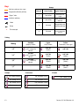
1
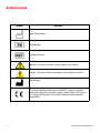
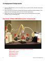
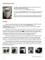
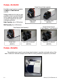
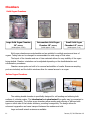
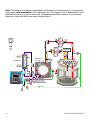
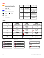
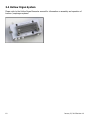
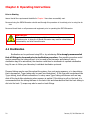
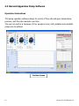
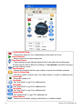
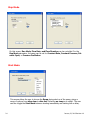
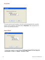
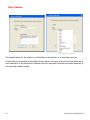
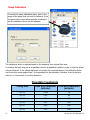
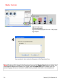
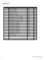
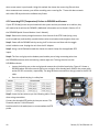
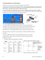
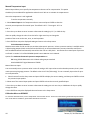
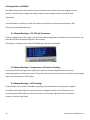
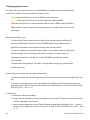
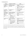
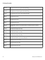
ORCA Bioreactor™ Operator’s Manual Harvard Apparatus Regenerative Technology, 84 October Hill Drive, Holliston, MA 01746 USA www.harvardbioscience.com ¨ 508.893.8999¨[email protected] 1 January 22, 2013 Revision 1.0 Contents Symbols 4 Overview 5 Chapter 1—Introduction 6 Chapter 2—Getting Started 2.1 Safety Requirements 7 7 2.2 Equipment Components 8 2.3 Heater Reservoir 9 2.4 Pumps 10 2.5 Chambers 11 Chapter 3—Assembly Instructions 3.1 Lung System 12-15 3.2 Heart 16 3.3 Aortic Valve System 17 3.4 Hollow Organ System 18 3.5 Pump Head Assembly / Disassembly 19 3.6 Accessories 19 Chapter 4—Operating Instructions 4.1 Sterilization 20 4.2 Reservoir Port Sizing 21 4.3 Controller Software 22-29 4.4 Decellularization 30 4.5 Recellularization 31 Chapter 5—Care & Maintenance 5.1 Parts List 2 32 33 Appendix A: Polestar Instructions 34-52 Appendix B: Frequently Asked Questions 53-55 January 22, 2013 Revision 1.0 Disclaimer: Use of the ORCA Bioreactor™ should be conducted by a trained and manufacturer qualified representative. Harvard Apparatus Regenerative Technology does not warrant unauthorized use of this product; Harvard Apparatus does not warrant that the operation of this product will be uninterrupted or error-free and makes no claim of warranty or condition. Harvard Apparatus reserves the right to change the instructions for use and any related products at any time without any prior notice and is not liable for any damages arising out of any change and/or alteration of the contents or product. This product is for RESEARCH USE ONLY. Copyright © 2013, Harvard Apparatus. All rights reserved. ORCA Bioreactor™ is a trademark of Harvard Apparatus. Harvard Apparatus, a division of Harvard Bioscience, owns the intellectual property rights to the ORCA Bioreactor. This material may not be reproduced, displayed, modified, or distributed without the expressed prior written permission of the copyright holder. U.S., international, and foreign patent applications are pending. 3 January 22, 2013 Revision 1.0 Symbols Used Symbol Definition Date of Manufacture Serial Number Catalogue Number Warning: This action will have a direct impact on the patient Caution: This action will have an impact on the product or operator Manufacturer This device complies with Directive 2006/95/EC relating to electrical equipment designed for use within certain voltage limits; this device also complies with Directive 2004/108/EC relating to electromagnetic compatibility. 4 January 22, 2013 Revision 1.0 Overview Harvard Apparatus Regenerative Technology partners with leading global scientists to provide specialized solutions. The company is uniquely positioned to develop advanced instrumentation to accelerate regenerative medicine, tissue engineering and cell therapy experimentation. From the beginning, in 1901, Harvard Bioscience companies worked closely with leading global researchers to produce products with the highest levels of performance, quality and support necessary for the new challenges of your life science research. We look forward to working with you to develop new tools to assist you in solving the new challenges of regenerative medicine from the lab bench to the patient. There are thousands of publications, in regenerative medicine to stem cell research, utilizing Harvard Apparatus products, but we are now introducing some newly developed products: one for regenerative organ generation and one for small volume cell delivery into organs. These products will serve researchers and physicians to accelerate both research and utilization of that research in patients. Harvard Apparatus Regenerative Technology provides: 5 Physiological bio-sensors and transducers to measure biological variables to better understand animal to cell physiology: mechanically, chemically, electronically Physiological data acquisition systems with advanced electronics, physiological data manipulation algorithms to measure, monitor, control and understand complex physiological events Physiological macro to nano fluidics infusion pumps Animal to cell electrophysiological monitoring systems Organ to cell perfusion bath and chambers to mimic physiological conditions to study drug, nutrient, gene and cell therapies Live cell imaging and perfusion chambers to better understand the affect of shear force, drugs, nutrition on cells and tissues Cell engineering tools from electroporation to pneumatic injectors January 22, 2013 Revision 1.0 Chapter 1: Introduction The ORCA Bioreactor is the first system designed to meet the needs of the modern regenerative medicine research scientist. The system is able to address the needs of both the decellularization and recellularization processes of various organs. Physiological conditions can be mimicked through control algorithms that regulate flow rates, profiles, and pressures. Critical readings can be taken from both inside the organ as well as in the support environment through the use of sensors. The Concurrent Method Development software logs all modifications and operator entries along with the result that was measured with the system sensors, allowing a complete review of an experiment and direct translation into a research method. A method storage system makes it easy to reproduce methods and conditions across multiple experiments. The image capture software allows for images to be captured in real time from cameras monitoring visible, IR, UV, and fluorescence; other systems such as ultrasound / ECHO are supported. 1.1 Warning and Caution Statements The use of a WARNING statement in this User Manual alerts you to a potential safety hazard. Failure to observe a warning may result in a serious injury to the user or patient. The use of a CAUTION statement in this User Manual alerts you to where special care is necessary for the safe and effective use of the product. Failure to observe a caution may result in minor injury to the user or damage to the product or other property. 1.2 Intended Use The ORCA Bioreactor is a system used for the purposes of monitoring and studying an isolated organ; it is intended for research use only. WARNING: Use of this device in non-research settings must be conducted under local Regulatory requirements; consult your local Regulatory Authority. 6 January 22, 2013 Revision 1.0 Chapter 2: Getting Started The following conditions must be met prior to using the In-Breath Bioreactor: 2.1 General Safety Requirements WARNING: The ORCA Bioreactor should only be used by qualified personnel who have been trained by the manufacturer or other Authorized Representative. Unauthorized use of this device is not recommended. WARNING: To prevent contamination, aseptic procedures must be followed and personal protective equipment must be worn at all times when handling and using the Bioreactor. WARNING: Wherever blood products are used, Universal Precautions must be followed. Facility Requirements Assure that the facility is able to provide a clean, safe, and suitable area for aseptic cell processing. It is recommend that all manipulations of the unit once sterile are performed in a biological safety cabinet of at least BCS Level 2 WARNING: Failure to provide a means to conduct aseptic cell processing may result in harmful contamination. 7 January 22, 2013 Revision 1.0 2.2 Equipment Components 1) Store the ORCA Bioreactor in a cool, dry place, free from dust and other potential contaminants until ready to use. 2) Assure that the ORCA Bioreactor package was received completely and without damage; if the package arrived as damaged contact your local technical support group. 3) Ensure that all parts the ORCA Bioreactor package and its peripheral devices are in good condition. Do not use damaged parts. Overview of Main ORCA Bioreactor Components E A B C B D A) Heater Reservoir & Temperature Control System B) Peristaltic Pumps C) Organ Chamber D) Pulsatile Pump E) Oxygenator 8 January 22, 2013 Revision 1.0 Heater Reservoir The heater is used to maintain temperature throughout the system to emulate physiological conditions. The reservoir holds a volume of 0.5L to 4L of media. The reservoir has built-in ports for interaction with the oxygenator and the organ chamber, as well as a port for a 12” temperature monitoring probe. There are two different sizes of bottles (large and small flow) that have different size ports to accommodate a wide variety of tubing and flows. Pumps Pumps are selected according to the organ and protocol requirements. The ORCA controller along with your pumps of choice address the needs of the decellularization and recellularization processes of various organs. All types of pumps may be controlled, including peristaltic, pulsatile and syringe. A maximum of four pumps are used simultaneously on a system. The ORCA controller may be configured to control either four peristaltic pumps or three peristaltic pump heads and a pulsatile blood pump. Both configurations typically include two single channel dual head peristaltic pumps. A 4th pump may be added to the four unit controller to serve as a spare unit. Pump head configurations may be altered at any time to meet the most demanding protocols. Selection of the pulsatile pump normally occurs when pulsatile flow rates in excess of 2L/min are required. This selection must be made at the time of purchase. If the “four peristaltic pump controller” is chosen, the fourth pump may be added at any time. A fourth peristaltic pump adds flexibility to accommodate elaborate protocols but is not required and can be added at a later time. These configurations can be used to accommodate protocols that require a perfusion pump, ventilation pump and a pump that will provide flow to the oxygenation system and a gas monitoring system. Exterior medium feed and waste bags can also be accessed using channels on the double head double channel pump. 9 January 22, 2013 Revision 1.0 Pumps—Peristaltic Single Channel (high capacity) Peristaltic pump heads are available in single and dual channel versions. Multiple heads may be used on each peristaltic pump to provide flexibility in flow range as well as the number of channels required for the most challenging protocols. High Capacity: Up to 1500mL/min Single Head (881001) Dual Offset Head (881003) Mid Capacity: Up to 500mL/min Dual Channel (mid capacity) Single Head (881002) Dual Head [4 channel] (881004) Single & Dual Channel (1 high capacity, 2 mid capacity) Dual Head [3 channel] (881005) Pumps—Pulsatile The pulsatile pump is used in some large animal systems to emulate ventricular action of the heart. It allows for minimal hemolysis and is ideal for moving emulsions, suspensions, and blood. 10 January 22, 2013 Revision 1.0 Chambers Solid Organ Chambers Large Solid Organ Chamber 14” (880420) Intermediate Solid Organ Chamber 10” (880429) Small Solid Organ Chamber 4.5” (880431) (holds approx. 32.8L) (holds approx. 11.6L) (holds approx. 1.4L) Solid organ chambers are autoclavable and are suitable for multiple species and sizes of organs. Tubing sets can be changed to accommodate the wide range of flow rates. The layout of the chamber and use of clear materials allows for easy visibility of the organ being studied. Chamber orientation can be adjusted depending on the decellularization and cellularization procedures. Chamber access ports are built in for removal and addition of media. Numerous sampling ports are included, and the built-in windows allow for manual access to an organ. Hollow Organ Chambers (880403) The rotating double chamber is specifically designed for cell seeding and culturing both surfaces of a tubular matrix. The intraluminal and extraluminal flow paths may be connected or maintained separately. The hollow organ chambers allow seeding and culturing of different cells types on either side of the tubular structure, providing homogeneity. The design allows for enhanced oxygenation and mass transport between the medium and cells. Large and small animal versions are available. 11 January 22, 2013 Revision 1.0 Chapter 3: Assembly Instructions 3.1 Lung System Note: The following is a diagram representing a configuration for the bioreactor for a large animal lung system (without cannulation of the pulmonary vein). This diagram is not a replacement for your laboratory’s protocols; be sure to follow your individual experimental procedures. Your individual laboratory’s setup may differ from what is depicted below. #2 #4 Ventilator (idle) #1 Gas in Oxygenator Gas out 1 PA trifold 11 tr out TC 4 5 10TC 9 #3 2 3 6 8 7 Reservoir (Port Details: pg. 25) 12 January 22, 2013 Revision 1.0 Key: Pumps Perfusion pathway into organ Oxygenation/Polestar pathway “Sipper” tube Ventilator pathway Pump # Head Config Typical Function 1 Dual offset Perfusion into organ 2 Dual offset Empty chamber to reservoir 3 4 channel Oxygenation and analytics pathway 4 3 channel Provides flexibility for the most challenging protocols Y Barb Clamp Thermocouple TC Tubing Sizing PharMed Opaque, flexible Tygon Clear, flexible Teflon Translucent, more rigid 1/8” L/S #16 (0.12”, 1.6mm ID) 881105 1/8” ID 721259 1/8” OD 1/4” L/S #17 (0.25”, 6.4mm ID) 881100 1/4” ID 721256 1/4” OD (30345) 3/8” L/S #18 (0.31”, 7.9mm ID) 881101 3/8” ID 721264 3/8” OD (30346) 1/2” — 1/2” ID 721268 1/2” OD (30347) Clamps Connectors 1/8” clamp (xxxxxx) 1/4” clamp (721670) 3/8” clamp (721671) 1/2” clamp (xxxxxx) 13 Y Barbs 1/8” connector (xxxxxx) 1/4” connector (xxxxxx) 3/8” connector 1/2” connector 3/8” Y barb (xxxxxx) (721577) (xxxxxx) January 22, 2013 Revision 1.0 Note: The following is a diagram representing a configuration for the bioreactor for a large animal lung system (with cannulation of the pulmonary vein). This diagram is not a replacement for your laboratory’s protocols; be sure to follow your individual experimental procedures. Your individual laboratory’s setup may differ from what is depicted below. #2 #4 Ventilator (idle) #1 Gas in Reservoir (Port Details: pg. 25) Oxygenator 1 Gas out 2 3 PA 11 O2 Pre #3 PV TC 4 5 10TC 9 tr 6 8 7 Trifold (post-organ) 14 January 22, 2013 Revision 1.0 Key: Pumps Perfusion pathway into organ Oxygenation/Polestar pathway Pump # Head Config Typical Function 1 Dual offset Perfusion into organ 2 Dual offset Empty chamber to reservoir 3 4 channel Oxygenation and analytics pathway 4 3 channel Provides flexibility for the most challenging protocols “Sipper” tube Ventilator pathway Polestar transducer pathway Y Barb T Barb Clamp TC Thermocouple Tubing Sizing PharMed Opaque, flexible Tygon Clear, flexible Teflon Translucent, more rigid 1/8” L/S #16 (0.12”, 1.6mm ID) 881105 1/8” ID 721259 1/8” OD 1/4” L/S #17 (0.25”, 6.4mm ID) 881100 1/4” ID 721256 1/4” OD (30345) 3/8” L/S #18 (0.31”, 7.9mm ID) 881101 3/8” ID 721264 3/8” OD (30346) 1/2” — 1/2” ID 721268 1/2” OD (30347) Clamps Connectors 1/8” clamp (xxxxxx) 1/4” clamp (721670) 3/8” clamp (721671) 1/2” clamp (xxxxxx) 15 Y Barbs 1/8” connector (xxxxxx) 1/4” connector (xxxxxx) 3/8” connector 1/2” connector (721577) (xxxxxx) 3/8” Y barb (xxxxxx) 3/8” to 1/8” T barb (xxxxxx) T Barbs January 22, 2013 Revision 1.0 3.2 Heart System Note: The following is a diagram representing a configuration for the bioreactor for a large animal heart system. Your individual laboratory’s setup may differ from what is depicted below. 16 January 22, 2013 Revision 1.0 3.3 Aortic Valve System Note: The following is a diagram representing a configuration for the bioreactor for a large animal aortic valve system. Your individual laboratory’s setup may differ from what is depicted below. 17 January 22, 2013 Revision 1.0 3.4 Hollow Organ System Please refer to the Hollow Organ Bioreactor manual for information on assembly and operation of trachea / esophagus systems. 18 January 22, 2013 Revision 1.0 Pump Head Assembly/Disassembly 3.6 Accessories Dino-Lite Cameras Refer to the Dino-Lite manual for instructions. PoleStar Gas Monitoring System For regenerative medicine applications, please see Appendix A for information regarding setup and calibration. For full manufacturer instructions, please refer to the PoleStar manual at http://polestartech.com/support/pdf/dsp4000-usermanual.pdf. 19 January 22, 2013 Revision 1.0 Chapter 4: Operating Instructions Prior to Starting Assure that all the requirements identified in Chapter 2 have been successfully met. Personnel using the ORCA Bioreactor should read through this procedure in its entirety prior to using the device. Personnel should train on all processes and equipment prior to operating the ORCA Bioreactor. WARNING: Failure to follow aseptic techniques and failure to train on all processes and procedures prior to using the In-Breath Bioreactor may result in critical delays, contamination, and other harmful events 4.1 Sterilization Sterilization can be performed using EtO or by autoclaving. It is strongly recommended that all fittings be loosened prior to sterilization procedure. One possible procedure would involve assembling the tubing set as it is to be used in the bioreactor and placing it into a sterilization bag to be autoclaved; the chamber could then be sterilized in a separate sterilization bag. Be sure to follow your laboratory’s individual sterilization protocols. Pharmed tubing may be used throughout the system. As a cost saving measure, or to have tubing that is transparent, Tygon tubing may be used (see illustrations). If the flow path is autoclaved has Tygon tubing, check all barb connections. In many cases Tygon tubing will become soft and may slide off the barb after autoclaving when pressure is applied. If the tubing is soft on the barb, it is recommended that the tubing that was on the barb is cut and discarded and that the fresh tubing is slid onto the barb. Ty-wraps may also be used on barb fittings. 20 January 22, 2013 Revision 1.0 4.2 Reservoir Bottle Configuration & Typical Usages Large Animal Note: This diagram depicts a typical usage for each of the reservoir bottle ports in a large animal system. Be sure to follow your laboratory’s individual protocols. 2 1 3 4 11 5 10 6 9 8 7 1) 3/4” tube; Pulsatile for trachea 2) 1/8” tube; Polestar transducer 3) 3/8” rigid tube; PA on lung or pressure control for valve peristaltic 4) 3/8” tube; PA on lung or pressure control for valve peristaltic 5) 1/8” rigid tube; Polestar transducer 6) 1/4” rigid tube; chamber circulation 7) 1/4” tube; chamber circulation 8) 1/4” rigid tube; oxygenator circulation 9) 1/4” tube; oxygenator circulation 10) 1/8”; thermocouple 11) 1/2” tube; Pulsatile for trachea Small Animal Note: This diagram depicts typical sizing & usage for each of the reservoir bottle ports in a small animal system. Be sure to follow your laboratory’s individual protocols. 1 2 3 4 11 10 5 6 9 8 21 7 1) 1/8” tube 2) 1/8” rigid tube; Polestar transducer 3) 1/4” rigid tube; PA on lung or pressure control for valve peristaltic 4) 1/4” rigid tube; PA on lung or pressure control for valve peristaltic 5) 1/8” tube; Polestar transducer 6) 1/4” rigid tube; chamber circulation 7) 1/4” rigid tube; chamber circulation 8) 1/4” rigid tube; oxygenator circulation 9) 1/4” rigid tube; oxygenator circulation 10) 1/8”; thermocouple 11) 1/8” rigid tube January 22, 2013 Revision 1.0 4.3 Harvard Apparatus Pump Software Operation Instructions This pump operation software allows for control of flow rate and gives temperature, pressure, and flow rate readouts over time. The user can control a maximum of four pumps at once; both pulsatile and peristaltic pumps can be utilized. The Main Screen 22 January 22, 2013 Revision 1.0 Enable/Disable Pump This primes a pump for use or deactivates a pump when not in use. Start/Stop Run Starts or stops the corresponding pump. Flow Rate Control These up/down arrows manually adjust the flow rate while the run takes place. The flow rate can also be altered by clicking on “x.xx ml/min” just below the pump icon and entering a value. Flow Direction Changes the direction that the pump rotates; a right arrow indicates clockwise. Create or Select Step Use this to create or select a Step. See “Step Creation” on pg.24 for additional info. Green Light Glows when pump is on. Step Mode See “Step Mode” on pg.22 for additional info. Start Mode See “Start Mode” on pg.22 for additional info. Stop Mode See “Stop Mode” on pg.23 for additional info. Repeat Mode See “Repeat Mode” on pg.23 for additional info. Pump Selector Choose from peristaltic, syringe, pulsed blood, or ventilator modes. 23 January 22, 2013 Revision 1.0 Step Mode On this screen, Run Mode, Flow Rate, and Flow Direction can be controlled. For the Run Mode parameter, the pump can be set for Constant Rate, Constant Pressure, Pulsatile Cycle, or Pressure Oscillation. Start Mode This screen allows the user to choose the Ramp during start-up of the pump, giving a range of options from ultra slow to ultra fast. Selecting no ramp is an option. The user can also toggle the Start Mode between starting immediately and starting with a delay. 24 January 22, 2013 Revision 1.0 Stop Mode This screen gives the user the option to have the run stop automatically after a specified amount of time has elapsed. The default setting is Stop Never, which continues the run until the user manually terminates it. Repeat Mode On this screen, the user can choose between No Repeat, Repeat Till (User Stop), Repeat Number of Times, and Repeat / Increase n Times. 25 January 22, 2013 Revision 1.0 Step Creation This window allows for the creation of a New Step or the selection of a previously used one. If the create box is checked, a New Step can be created, with input boxes for the Step Name and a brief description. If the select box is checked, the user may select from the drop-down menu any of the previously created presets. 26 January 22, 2013 Revision 1.0 Pump Calibration To access the pump calibration menu, click on the image of the pump that you wish to calibrate. From this menu, the correct tubing size can be selected and the calibration factor can be adjusted. The calibration factor is selected based on the deviation from optimal flow rate. In practice, the user may run at a specified rate into a graduated cylinder in order to test the actual volume delivered. If the volume delivered is less than the expected amount, the calibration factor can be set at a value greater than 1 to compensate for this deviation. Likewise, it can be set at a value 0<x<1 to account for positive deviation. Flow Rate Constraints 27 Tubing Size Flow Rate Minimum (ml/min) Flow Rate Maximum (ml/min) L/S 13 0.018 18 L/S 14 0.63 63 L/S 16 0.24 240 L/S 25 0.51 510 L/S 17 0.84 840 L/S 18 1.14 1140 January 22, 2013 Revision 1.0 Master Controls 1 2 3 4 1) starts all pumps 2) stops all pumps 3) incrementally adjusts flow rate of all pumps 4) notepad 4 Any experiment notes entered will appear on the Experiment Log. Note: All actions will be logged in the Experiment Log once the Master Start button is clicked. Any experimental changes will continue to be logged until the Master Stop icon is clicked. This is to prevent logging extraneous information while retaining valuable information about adjustments 28 January 22, 2013 Revision 1.0 Heater Temperature Control & Pressure Channel Calibration Access the Temperature Control menu through Tools—>Heater. Probe to Control allows the user to select between four different probes, labeled TC-1 to TC-4. Heater Control can be set to either Enabled or Disabled Set Point allows the user to set the temperature in degrees Celsius. The Pressure Channel Calibration menu can be accessed through Tools—>Calibration—>Pressure. First select the desired Pressure Channel. The Filter may be set to either Mean or Raw. The Actual Value is the instantaneous value for the pressure reading. Average Value is the average reading over a few seconds. The Average Cycle serves as an “update light” to let the user know when the average has been updated. Use the Zero button to zero the actual value reading, and Cal Value along with the Calibration button to calibrate pressure readings. 29 January 22, 2013 Revision 1.0 Decellularization 30 January 22, 2013 Revision 1.0 Recellularization 31 January 22, 2013 Revision 1.0 Chapter 5: Care & Maintenance Cross-Infection Prevention, Biohazardous Waste, and Product Disposal Cross-Infection Prevention/Universal Precautions All blood products or products potentially contaminated by blood or other body/animal fluids should be treated as potentially infectious materials. Personal protective equipment should be worn at all times when using the In-Breath Bioreactor to protect personnel from becoming contaminated as well as to help prevent cross-infection and cross-contamination. Bench tops, equipment, and other potentially contaminated surfaces should be cleaned and disinfected according to the manufacturers’ and/or the facility’s procedures. Any article used to clean potentially contaminated surfaces should be disposed of as Biohazardous Waste. CAUTION: Failure to use the manufacturers’ cleaning and disinfecting procedure could result in damage to the surface or equipment. Biohazardous Waste Dispose of biohazardous waste according to local Regulatory requirements. Accessories Peristaltic pumps with isolated heads capable of being used in a CO2 incubator. Cleaning Flush all fluid paths with deionized water and either follow with or wipe with 70% IPA. Stainless steel parts may be sonicated. 32 January 22, 2013 Revision 1.0 Parts List Amount 33 Equipment Part Number Clamp, 1/8” (3.18mm) xxxxxx Clamp, 1/4” (6.35mm) 721670 Clamp, 3/8” (9.53mm) 721671 Connector, 1/8” (3.18mm) xxxxxx Connector, 3/8” (9.53mm) 721577 PharMed tubing, L/S 16 (0.12”, 3.1mm ID) 881105 PharMed tubing, L/S 17 (0.25”, 6.4mm ID) 881100 PharMed tubing, L/S 18 (0.31”, 7.9mm ID) 881101 PharMed tubing, L/S 25 (0.19”, 4.8mm ID) 881102 Teflon tubing, 1/8” (3.18mm) OD xxxxxx Teflon tubing, 1/4” (6.35mm) OD 30345 Teflon tubing, 3/8” (9.53mm) OD 30346 Teflon tubing, 1/2” (12.7mm) OD 30347 Tygon tubing, 1/8” (3.18mm) ID 721259 Tygon tubing, 1/4” (6.35mm) ID 721256 Tygon tubing, 3/8” (9.53mm) ID 721264 Tygon tubing, 1/2” (12.7mm) ID 721268 Y Barb, 3/8” (9.53mm) 721588 3/8” to 1/8” T fitting xxxxxx January 22, 2013 Revision 1.0 Appendix A: PoleStar Setup and Operation Application Instructions Polestar Fluorescence-based Optical Biosensors Harvard Apparatus Version 1.21 061112 Written primarily for applications involving isolated organ and tissue. See manufacturer’s manual for details regarding use in standard applications. This guide is NOT a replacement for the manufacturer’s manual. 34 January 22, 2013 Revision 1.0 Table Of Contents 1 Introduc on, Manufacturer’s details 2 Safety Note 3 General Descrip on, Applica on 3.1 Measurement Specifica ons 4 Ini al Setup of DSP4000 Unit/Quick‐start Guide 4.1 Installing the USB onto Computer 4.2 Connec ng RTD Probes to Sensors 4.3 Integra ng Sensors into System Setup 4.4 Connec ng DSP4000 to Data Acquisi on System 5 Calibra ng Sensors, General 5.1 Set Barometric Pressure 5.2 Units Conversion, Data Acquisi on 2‐Point Calibra on 5.3 Oxygen Sensor Calibra on 5.4 Carbon Dioxide Sensor Calibra on 5.5 pH Sensor Calibra on 6 Viewing Data on DSP4000 6.1 Channel Readings – O2, CO2, pH Parameters 6.2 Channel Readings – Temperature and Pressure Readings 6.3 Channel Readings – ACG Readings 7 Changing expired sensors 7.1 Upda ng Lot Number for New Sensor Calibra on 8 Cleaning and Maintenance 9 Troubleshoo ng Guide/ Ordering Informa on 35 January 22, 2013 Revision 1.0 1 Introduc on, Supplier’s detail These Opera ng Instruc ons describe the func on and use of the DSP4000 Op cal Process Monitor. This manual is to be considered part of the system for its proper use and opera on and should be kept close to the system at all mes. The informa on provided on the DSP4000 has to be read in conjunc on with the remaining system documenta on for the applica on to which it is being put to use. All the informa on contained in these instruc ons has been drawn up a er careful examina on but does not represent a warranty of product proper es. Altera ons in line with technical progress are reserved. This DSP4000 unit is manufactured by: POLESTAR TECHNOLOGIES and supplied to you by HARVARD APPARATUS. All inquiries regarding this system addi on/applica on should be directed to Harvard Apparatus or to the Harvard Apparatus Authorized Distributor from whom this unit was purchased. Harvard Apparatus 84 October Hill Rd Holliston, MA 01746 Phone (United States) : 800‐272‐2775 Phone (others) : 508‐893‐8999 email: [email protected] Harvard Apparatus has loca ons in Canada, United Kingdom, Germany, Spain, and France. 2 Safety Note Opera on in hazardous areas and/or a flammable atmosphere is not permi ed. 3 General Descrip on, Applica on The DSP4000 Op cal Process Monitor can be configured for 1, 2, 3, or 4 Channels (defined by the number of LED modules present in the system). Units are iden cal in func onality 36 January 22, 2013 Revision 1.0 though the total sensor capacity may differ. In the descrip ons below all configura ons will be referred to as the “DSP4000.” The DSP4000 is an Op cal Process Monitor designed to emit and sense light in a specific range of wavelengths for the purpose of determining the concentra on of the presence of the parameter(s) for which the connected sensor(s) is (are) configured (pH, O2, CO2). The sensors are supplied in a range of configura ons to meet the various applica on specifica ons of the end users. Most frequently researchers who purchase the system from Harvard Apparatus will be u lizing flow‐through sensors for use in one of the many perfusion systems available; however, in vivo applica ons are also common in which a puncture probe may be used. General purpose probes can also be used and immersed in any fluid. O2 and CO2 sensors can operate with fluid or with gas and therefore a wide variety of applica ons is possible. The DSP4000 can be configured for 1, 2, 3, or 4 channels for one, two or all three of the parameters currently available (pH, O2, CO2). A dual channel system can be configured for measurement of 2 of the same parame‐ ters (requiring only one purchase of the firmware for that measurement) or 2 different parameters (as long as the firmware for the parameters of interest are both purchased) or 3 different parameters, with only 2 of the 3 sensors connected at any one me. This manual supplement is primarily designed to guide researchers u lizing the system for isolated perfused organ and ssue applica ons or who will be calibra ng their sensors in the ranges outlined in sec on 3.1 of this document. 3.1 Measurement Specifica ons Oxygen Measurement ranges available: High: 0‐500% Air Sat Low: 0‐20% Air Sat Units of Measurement available: O2 % O2 % Air Sat O2 PPM (or PPB, or SUB‐PPB) O2 mmHg O2 deg pH 37 January 22, 2013 Revision 1.0 Measurement ranges available: Low Physiologic: 4 ‐ 7 Mid Physiologic: 5.5 – 10 Carbon Dioxide Measurement range: 0 – 30 % Units of measurement available: CO2 % CO2 mmHg SMR 4 Ini al Setup of DSP4000 Unit/Quick‐start Guide Please refer to the Quick Start Guide that was supplied with your DSP4000 unit. It is especially important to do the following upon ini al setup: * Open the door to the unit (loosen screws with fingers or screwdriver) and do the following: ‐ Remove the USB Key and plug it into your PC and copy the contents to your Desktop (or ferred loca on on your computer). Take special note of the manual (recommended to print a copy if desired). Return the USB Key to the Unit ‐ Verify that the toggle switch (next to USB KEY) is in the “OFF” Posi on before plugging in the AC Power Adapter (See Figure 2‐3 of DSP4000 Op cal Process Monitor User’s Manual) pre‐ * Turn “ON” the DSP Monitor by flipping the toggle switch. The Monitor should warm up for 30 minutes before first me use and at any me when powering on from a full shut down (where the toggle switch inside the unit is in the “off” posi on). Generally the unit can be le in Standby Mode (the Main Menu is displayed) between uses unless one of the following requires a full shut down: • You are connec ng I/O as described in Sec on 4 (“Electrical Connec ons”) in the DSP4000 User’s Guide • You need to upgrade the opera ng system to a new version. The DSP4000 will prompt you to upgrade the so ware when you restart the system (see Figure 2‐12) • There will be an extended period between uses 38 January 22, 2013 Revision 1.0 * Refer to Quick Start Guide for connec on of Fiber Op c Cables. NOTE: You must align the small tab on the ST Connector on your sensor with the notch in the Fiber Op c cable or the fi ng will not connect. * Recommended not to re‐screw lid un l your setup is complete and the unit is fully calibrated and ready to use * NEVER use a Power Strip to power on and off your DSP Unit. This results in a “fuzzy” power cutoff that interferes with the memory and proper func oning of the unit. * Proper methods for powering down the DSP4000: ‐ Go to Main Menu and select “Turn Off DSP4000.” This allows you to put the unit into standby and avoid having to wait for a 60 minute warm‐up period at the next use ‐ If you wish for a full power shutoff, then a er the above step, open the DSP4000 and flip the toggle switch to “OFF.” * Saving the Log file is op onal. If you have performed a calibra on procedure or changed any other se ng, or recorded measurement data onto the log file, it is advisable to save the log file. 4.1 USB Key * It is important to iden fy which sensor was assigned to each channel in order to match the sensor/fiber op c cable and channel with the correct parameter, units and calibra on data that were used during tes ng. Instruc ons on how to do this are described in sec on 2.4 of the DSP4000 Op cal Process Monitor User’s Manual. You can change the assignments later by loading each sensor’s calibra on file to a different channel, as discussed in Chapter 3, “Managing Configura on Files.” * Removing the USB Key while unit remains under power (without powering off the DSP4000): For full instruc ons please refer to DSP4000 Op cal Process Monitor User’s Manual sec on 2.8. This is done when you wish to review the log file or update lot #/calibra on informa on (such as 39 January 22, 2013 Revision 1.0 when a new sensor is purchased). Using this method also closes the current log file such that when measurement resumes, you will be recording onto a new log file. **note this does not work with older USB Keys where the so ware may freeze 4.2 Connec ng RTD (Temperature) Probes to DSP4000 and Sensors If your RTD Probe(s) were not purchased with the system and are purchased as an add‐on, they will need to be wired into the DSP4000. (Addi onal informa on can be found in Sec on 4.2 of the DSP4000 Op cal Process Monitor User’s Manual.) Step 1: Remove the three‐pronged connector from the end of the RTD Probe (using a very small screwdriver) and carefully unwind the bare wire termina ons and straighten them out Step 2: Power off the DSP4000 unit by turning it off in the menu and then with the toggle switch inside the case. Unplug the unit from the AC Adapter. Step 3: Using a small flathead screwdriver loosen the metal clamps for the applicable RTD inputs. Step 4: The four cord grips on the bo om panel enable you to bring connec ng wires into the DSP4000 enclosure while maintaining a water‐ ght seal. To bring the wire into the DSP4000 enclosure: Loosen the locking nut on the cord grip and remove the cylindrical metal plug. Figure 4‐2 shows a DSP4000 where the le ‐most and right‐most cord grips have already been used for the power cable and an RS‐232 connec on, respec vely. The plug has been removed from the grip next to the RS‐232 cable. Store the cylindrical plug in a safe place. Step 5: Insert the bare wires as per the following table. Clamp down using screwdriver Connect the threaded RTD probe p into your sensor. The Flowcells and the Tri‐fold Flowcells both have built‐in threaded ports to accommodate the RTD probe. 40 January 22, 2013 Revision 1.0 4.3 Integra ng Sensors into System Setup The Flow cells in the cell mounts have male and female Luer termina ons. **Make sure that you always use a non‐gas permeable or low gas‐permeable tubing such as Tygon R‐3603 or Tygon S‐50‐HL.** Using a Luer‐Barb connector kit, you can fit mul ple barb sizes to the Luer termina ons or connect these to each other end‐to‐end (for mul ple sensor types). The Tri‐fold Flowcell has four threaded holes set in a square configura on (0.20" deep, 10‐32 Thread/M5 Thread) to accommodate mul ple moun ng op ons. It can also be placed on the lab bench or clamped using rod/clamp system to the relevant por on of the perfusion system. 4.4 Connec ng DSP4000 to Data Acquisi on System • If you purchased a DAQ‐DSP4000 Interface Cable, this has come preinstalled and configured to work with a standard 0‐10V Analog to Digital Data Acquisi on System (such as a PowerLab, Data, NI‐DAQ, iWorx, Biopac, or other). These cables terminate in a Male BNC connector. U lizing DAQ hardware that has analog inputs other than female BNC requires the use of an adapter to your input type or removal of the BNC connector to bare leads. • Connect the BNC output cables to the Analog Input BNC connectors on your Data Acquisi on System. Please connect to the channel on which you wish the par cular reading to be recorded. The output range of the analog output is as follows: Minimum measurement (4mA) is 2V output Maximum measurement (20mA) is 9.9V 41 January 22, 2013 Revision 1.0 5 Calibra ng Sensors, General Calibra on gas and solu on: The DSP4000 typically only requires a 1‐point calibra on at a value near the range in which you will be measuring: • pH measurements, use a buffer standard of 8.0. • When a 95% O2/5% CO2 gas mix is the gas used for aera on and pH maintenance of your perfusion buffer, this gas can be used for the 1 point calibra ons of both Oxygen and Carbon Dioxide (gas‐saturate a non‐bicarbonate buffered solu on). If your perfusion system requires buffers to be deoxygenated (such as in lung applica ons) or use buffer equilibrated with room air, then air‐saturated solu on (non‐bicarbonate buffered) should be used for calibra on. In these situa ons it is common to use some 5% CO2 gas mix for the 1 point calibra on of the CO2 sensor (such as 5% CO2) with balance air, or 95% N2/5% CO2. TECHNICAL NOTE: Oxygen Sensor calibra on is always performed based on air satura on and not dissolved oxygen satura on. 20.9% DO = 100% Air Satura on. 95% DO = 454% Air Satura on If a 2 point calibra on needs to be performed, then the following zero/low standards should be used: pH: buffer pH 5 or lower (this is the minimum output of the Polestar) CO2: Room Air‐equilibrated dis lled water, which has a CO2 level of 0% or Nitrogen Gas O2: pO2 zero solu on (Catalog Number 73‐3812) or Nitrogen gas saturated solu on The op cal sensing films consist of fluorescent indicator chemistries immobilized in either hydrophilic (pH sensor) or hydrophobic (DO and CO2 sensors) polymer membranes. The gaseous (O2/CO2) or ionic (H+) species of interest move freely between the solu on and interior por ons of the sensing membranes to maintain an equilibrium of par al pressure (O2, CO2) or chemical poten al (pH). The me to reestablish the equilibrium condi on following a change in the solu on is dependent upon the species rate of diffusion through the membrane (faster at 37°C). For the purpose of calibra on, it is recommended that the user allow a minimum of 10 minutes exposure of cycling the calibra on solu on through the sensor to ensure complete equilibra on of the sensing film. Note: it is important that the calibra on solu on flow over the sensor during the calibra on process. Failure to use a flowing calibra on solu on can affect the calibra on results 42 January 22, 2013 Revision 1.0 (flow through a flow‐through sensor or use a magne c s rrer). If calibra ng with gas, the gas should flow through the sensor for at least 5 minutes. Applica on Note: If you wish to scale the OUTPUT of the DSP4000 for higher resolu on within a smaller range of the total range of the sensor, use the DSP Configura on U lity (see sec on 4.6 “Scaling Values in the Calibra on File” of the DSP4000 Op cal Process Monitor User’s Manual). Temperature Influence on CO2 and O2 Measurements: For accurate calibra ons and measurements, the temperature needs to be known and ac vely compensated. You should have the temperature either manually set at the temperature at which the calibra on is taking place (you can put a small temperature probe into the line to measure) or you can use an RTD probe that is wired into the DSP4000 unit. The RTD probe is the preferred method as you will have con nuous temperature compensa on and therefore will not need to change any temperature se ngs on the DSP4000 between calibra on and measurement. The DSP4000 can be configured such that a single RTD probe can provide the con nuous temperature source for all channels. This is appropriate for a sensor like the Tri‐fold Flow Cell. If sensors are located in different areas, then mul ple RTD probes can be used. A Channel is instructed to look at either a Common Source RTD (for example, you can designate the RTD Probe on Channel 1 to be the Common Source and the other temperature‐dependent sensor on the Tri‐Fold Flow cell can be directed to use the Common Source). If another individual sensor is located elsewhere, then a second RTD probe can be installed on that channel and you would then direct the DSP4000 to use “RTD” as the source for that Channel. If an RTD probe is not used, then the temperature can be set manually. . 43 January 22, 2013 Revision 1.0 Manual Temperature Input Manual Input allows you to specify the temperature value to use for compensa on. This op on should only be considered for applica ons where there is li le or no varia on in temperature or where the temperature is well regulated. To set the temperature manually: 1. Select Manual Input in the Temperature Source menu and press ENTER to show the currently set temperature for manual input. The default is 20° C. The range is ‐20° C to 100° C. 2. Press the up or down arrow to increase or decrease the se ng by 0.1° C, or hold the key down to rapidly change the value. Press the le or right arrow keys to change the posi on of the cursor to the tens, ones, or tenths posi on. 3. Press ENTER to accept the displayed se ng and return to the Setup menu. 5.1 Set Barometric Pressure Measurements taken for CO2 and O2 are sensi ve to barometric pressure. Unless a pressure monitor is available with a 4‐20mA analog output (which can be fed into the DSP unit), an accurate barometric pressure should be read from a NIST cer fied barometer and manually entered into the unit on a daily basis. Instruc ons for manual input of pressure are found in sec on 5.6.1 of the DSP4000 Op cal Process Monitor User’s Manual. Op ons for con nuous barometric pressure compensa on are: RM Young 61302L Barometer with 4‐20mA analog output standard Vaisala BAROCAP® Digital Barometer PTB330 Manual Pressure Input You can manually enter a pressure value in units of mmHg or PSI. Input values must be absolute pressure, that is, baro‐ metric pressure plus gauge pressure. The default value is 14.7 PSI (760 mmHg). To use a manually input value for pres‐ sure compensa on: 1. Select Pressure from the Setup menu and press ENTER to display the current se ng, and then press ENTER to show the pressure input op ons. 2. Select one of the manual input op ons and press ENTER to show the currently specified input. 3. Press the up or down arrow to increase or decrease the se ng one unit at a me, or hold down the key to rapidly change the value. 4. Press ENTER to accept the displayed value and return to the Setup menu. Calibra on Menu on DSP4000 To reach the calibra on menu, select “Setup Mode” from the Main Screen. Choose the Channel being calibrated and press ENTER. Then scroll down to Calibra on, press ENTER and follow instruc ons. 44 January 22, 2013 Revision 1.0 5.2 Units Conversion, Data Acquisi on 2‐Point Calibra on A er the DSP4000 Op cal Process Monitor has undergone the 1‐point calibra on(s) for the channel(s) installed, you may proceed with applying the units conversion/calibra on to your data acquisi on system so ware. For units conversion in LabChart, follow these steps: 1. Connect the Analog Output Cables to the Powerlab 2. Ensure that the Range is set at 10V on the Input Amplifier. Set up the channel appropriately in the Channel Se ngs Window or individually on each channel as per LabChart instruc ons 3. Press Start and record the upper calibra on value that was used for the 1‐point calibra on. Once the reading is stable and you have your sample captured, proceed to step 4. Make note of the reading on the DSP4000 unit during this trace recording as this will be the value used in your units conversion. 4. Apply the low/zero condi ons to the flowcell. For example, for oxygen this may be the upper calibra on point of 95% O2 followed by buffer that has been aerated for 30 minutes or which is equilibrated with the aera on gas. Con nue recording un l the stable phase is reached and you have a suitable trace for calibra on. Make note of the reading on the DSP4000 unit during this trace recording as this will be the value used in your units conversion. 5. Highlight the full calibra on data trace (high and low point) for one sensor type at a me and choose “Units Conversion” from the right‐click drop down for that channel. Follow normal calibra on procedure using the values obtained from the DSP for the high and low points. 5.3 Oxygen Sensor Calibra on It is recommended to use the 1‐point calibra on on the DSP4000. When complete, put the DSP4000 into RUN MODE and collect data into LabChart. Switch to the lower oxygen solu on (such as aerated buffer), to capture the low value. Once done, stop data recording and highlight the full sec on of data that includes both the high and low calibra on points. Right click on the range in the channel and choose “Units Conversion” from the drop‐down menu. Use the values displayed on the DSP4000 for the 2 point calibra on in LabChart. 45 January 22, 2013 Revision 1.0 5.4 Carbon Dioxide Sensor Calibra on A 1‐point calibra on should be performed on the DSP4000 when a known gas concentra on, e.g. 5%, is not read accurately on the DSP Display. Typically this calibra on point is at 5% as that is the concentra on of CO2 that is used to maintain proper pH in most bicarbonate buffers used in perfusion systems. When the 1‐point calibra on is complete, put the DSP4000 into RUN MODE and collect data into LabChart. Switch to the zero gas or solu on for 5 or 10 minutes (respec vely) (or un l the reading has fully stabilized) and con nue to collect data for the low point. Once done, stop data recording and highlight the full sec on of data that includes both the high and low calibra on points. Right click on the range in the channel and choose “Units Conversion” from the drop‐down menu and use the values that are displayed on the DSP4000 for the 2 point calibra on in LabChart. 5.5 pH Sensor Calibra on When the pH reading on the DSP4000 is not accurate, a 1‐point calibra on can be performed on the DSP4000. A calibra on buffer of a value near the pKa of the sensor is used. For a 5.5‐10 pH sensor, the pKa, or midpoint of the response curve falls, at 8.2, therefore we choose pH 8 as the preferred calibra on buffer for this sensor. When complete, put the DSP4000 into RUN MODE and collect data into LabChart. Switch to pH 6 or other lower pH solu on that falls below your op mal area of interest. Calibra on Solu on for 10 minutes (or un l the reading has fully stabilized) and con nue to collect data. Once done, stop data recording and highlight the full sec on of data that includes both the high and low calibra on points. Right click on the range in the channel and choose “Units Conversion” from the drop‐down menu and use the values that are displayed on the DSP4000 for the 2 point calibra on in LabChart. 46 January 22, 2013 Revision 1.0 6 Viewing Data on DSP4000 Run Mode will by default show you the channel measurement data for the sensor plugged into that channel. The AUX bu on changes the display to give current readings of other channel‐specific informa on: If the AUX bu on is pressed, it scrolls the screen through displays of temperature/pressure, AGC Value, and Channel Measurements. 6.1 Channel Readings – O2, CO2, pH Parameters These are displayed as in the image to the le . The channel designa on followed by the numerical value and then the units that have been assigned to that channel. This display is showing a three channel DSP4000 with two channels disabled. 6.2 Channel Readings – Temperature and Pressure Readings Pressing the AUX key will give you a display that reads the channel designa on followed by the temperature/pressure values per channel. These will only show real me data from an ac vely compensa ng input source (barometer or RTD probe). 6.3 Channel Readings – AGC Readings These readings can be useful for feedback regarding sensor effec veness or placement in regards to the fiber op c cable. High AGC readings indicate a high gain applied to the LED which can be caused by photo‐bleaching of the sensor chemistry or by improper alignment of the chemistry in rela on to the fiber op c cable. 47 January 22, 2013 Revision 1.0 7 Changing expired sensors The Status LED in the upper right corner of the DSP4000 front panel provides a visual indica on of the AGC or RAGC level during opera on. The Status LED is: • Green when the AGC level is less than 3000 for all four channels • Yellow when the level for least one channel is between 3000 and 3500 • Red when the AGC for one channel exceeds 3500. An AGC or RAGC reading of 3500 or higher indicates a need to replace the sensing element, or an obstruc on or break in the op cal path. When the Status light is red: 1. Check the AGC level of each channel to iden fy the channel causing the Status LED alert. See “AGC Display” Sec on 5.8 of the DSP4000 Op cal Process Monitor User’s Manual for informa on on accessing the display from the Setup menu. 2. Inspect the BioProbe connec ons and the op cs on the problem channel to determine whether the high AGC is caused by an obstruc on or break in the op c path. See “Inspec on Procedures” in Sec on 6.1.1 of the DSP4000 Op cal Process Monitor User’s Manual. 3. Replace the sensing element if the AGC is s ll high a er resolving any problems with the fiber op c path. Flow‐cells (glass insert with chemistry painted internally): 1. Remove the glass insert by loosening the screw with an allen/hex wrench and sliding the flow cell out. 2. Contact Harvard Apparatus or your Harvard Apparatus Appointed Distributor for the correct re placement part number for the flow cell insert for your measurement (i.e. O2 PPB, O2 PPM, O2 Sub‐ PPB, CO2, pH 5.5 – 10 or 4 ‐ 7). Tri‐Fold sensor: 1. Remove the Fiber Op c cable(s). 2. Using a wrench (if unable to remove with fingers), unscrew the ST Connector on the channel that needs a replacement sensing disk. 3. Contact Harvard Apparatus or your Harvard Apparatus Appointed Distributor for the correct re‐ placement part number for your sensor type (i.e. O2 PPB, O2 PPM, O2 Sub‐PPB, CO2, pH 5.5 – 10 or 4 ‐ 7). 48 January 22, 2013 Revision 1.0 Puncture probe: 1. Remove the puncture probe from the fiber op c cable. This sensor is purchased as in the catalog as it has no replacement por ons as it is a disposable item. 2. Update the configura on file on the USB‐KEY, as described in “Loading the File onto the USB‐KEY” Sec on 3.4 of the DSP4000 Op cal Process Monitor User’s Manual. BioProbe: 1. Unscrew the p from the BioProbe by twis ng it counter‐clockwise. CAUTION: The sensing element is designed to seal when finger‐ ght. Never use pliers or any other tool to loosen or ghten the sensing element, as the tools can damage the sensing element and probe body. 2. Screw the replacement element onto the end of the probe. Calibra on informa on for the sensing element is contained in a calibra on file that includes the sensor type and the calibra on factors for all elements in the same manufacturing lot. You can download the calibra on file from the Support area on the Polestar Technologies web site. 3. Update the configura on file on the USB‐KEY, as described in “Loading the File onto the USB‐KEY” Sec on 3.4 of the DSP4000 Op cal Process Monitor User’s Manual. 7.1 Upda ng Lot Number for New Sensor Calibra on See Chapter 3 (“Managing Configura on Files) of the DSP4000 Op cal Process Monitor User’s Manual for using the Configura on U lity to assign new lot numbers to the measurement channel. The configura on u lity is also used to reassign channels to different measurements. 49 January 22, 2013 Revision 1.0 8 Cleaning and Maintenance Op cal Sensors are not affected by ambient light when in use; however, they are sensi ve to light and should be stored in the dark when not in use. The sensors can be cleaned using MUCASOL, which is preferred when using the sensors in conjunc on with a Hugo‐Sachs Isolated Organ or Tissue Perfusion System whereby there are we ed components constructed from Plexiglas. If the fiber op c cables have been detached and stored or if they are otherwise possible dirty you should use a piece of scotch tape to tap on the p to remove par culate ma er. Addi onal in‐depth maintenance informa on can be found in Chapter 6 “Care and Maintenance” of the DSP4000 Op cal Process Monitor User’s Manual. You will need the following items to inspect and maintain the DSP4000: De‐ionized water Chem Wipe® or so lint‐free cloth Scotch tape Magnifying glass Compressed air or nitrogen Adjustable wrench. All Polestar sensors (including sensing elements, iDots, peel and s cks, and puncture probes) are sensi ve to ambient light and will photo‐bleach over me unless stored in a dark place between uses. Bright sun light will accelerate the aging process of the sensor. Photo‐bleaching affects the useful life of the sensing element, but not the accuracy of measurements. 50 January 22, 2013 Revision 1.0 Troubleshoo ng Guide If none of the above apply and you are seeing “AGC Limit,” please check to make sure that the sensor chemistry is as close to the LED/fiber op c as possible. If using a glass flow‐cell, check to make sure that it is seated in the cell mount such that the chemistry is between the light and the perfusate/media. 51 January 22, 2013 Revision 1.0 Ordering Informa on 52 88‐0258 O2 Replacement Kit (sensor, glass window & O‐Ring) 88‐0260 pH Replacement Kit (sensor, glass window & O‐Ring) 88‐0261 CO2 Replacement Kit (sensor, glass window & O‐Ring) 880258 O2 Replacement sensor 880260 pH Replacement sensor 880261 CO2 Replacement sensor 88‐0263 REPLACEMENT QUARTZ 02 PPB SENSOR INSERT FOR SINGLE QUARTZ FLOWCELL MOUNT 72‐8161 BUFFER SOLUTION pH 8.00, 500ml 72‐8162 BUFFER SOLUTION pH 7.41, 500ml 72‐8163 BUFFER SOLUTION pH 6.00, 500ml 72‐8164 BUFFER SOLUTION KIT: pH 6, 7.41, 8, 500ml/EA 880194 Trifold Connec ons Kits 1/16” 880195 Trifold Connec ons Kits 1/8” 880196 Trifold Connec ons Kits 1/4” January 22, 2013 Revision 1.0 Appendix B: Frequently Asked Questions Hollow Organ Bioreactor Is the retainer clamp missing from my unit? The retainer clamp design did not fit as well as it was supposed to, and since it did not seem to be necessary, we have not been shipping it with the product. A new clamp is in the process of being developed to make sure the drive mechanism does not slip and disengage itself. How does the "seal wash inlet" and outlet work (for hollow organ systems)? This passage is designed to take a non-salt solution and flush it through a separate space between the two outside O-rings on the driveshaft. This will prevent any buildup of evaporated salt crystals from forming on the turning shaft during long periods of use. As an example, an intravenous drip bag with water set to between .1 and .5mL per minute to continuously flush the seal wash path could be used. For the hollow organ bioreactor, should I sterilize using plasma sterilization or would autoclaving work? The materials of construction are Teflon reservoir, stainless steel baseplate, driveshaft, and valves, silicone rubber O-rings, Kynar Luer fittings, polycarbonate cover, and PEEK arbor components. All of these materials will withstand steam sterilization. One CAUTION, however…. Please disassemble all the valve and driveshaft parts from the Teflon block before steam sterilization. The high temperature may cause the machined holes in the Teflon to become deformed by the parts pressed into them. Reinstall the valves and driveshaft after the Teflon cools down. The Kynar Luer fittings have been installed using silicone adhesive to hold them in place and prevent leaks. It should not be necessary to remove these fittings from the Teflon because of the sterilization process. Can washing be done with [reagent]? These materials of construction will withstand virtually all biological reagents and cold sterilization agents (such as Cidex, Cidex OPA, Mucasol, etc). 53 January 22, 2013 Revision 1.0 Appendix B: Frequently Asked Questions 54 January 22, 2013 Revision 1.0 Appendix B: Frequently Asked Questions 55 January 22, 2013 Revision 1.0 Harvard Apparatus Regenerative Technology, 84 October Hill Drive, Holliston, MA 01746 USA www.harvardbioscience.com ¨ 508.893.8999¨[email protected] 56 January 22, 2013 Revision 1.0