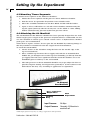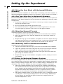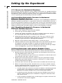
1
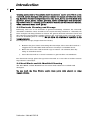
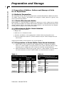
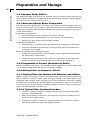
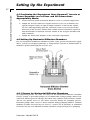
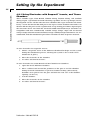
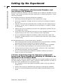
Diffusion
Chamber System
User’s Manual
Vertical Ussing & Horizontal
Diffusion Chamber Systems MA1 66-00XX
Publication 5403-007-REV-D
WEEE/RoHS Compliance Statement
EU Directives WEEE and RoHS
To Our Valued Customers:
We are committed to being a good corporate citizen. As part of that commitment,
we strive to maintain an environmentally conscious manufacturing operation. The
European Union (EU) has enacted two Directives, the first on product recycling
(Waste Electrical and Electronic Equipment, WEEE) and the second limiting the use
of certain substances (Restriction on the use of Hazardous Substances, RoHS).
Over time, these Directives will be implemented in the national laws of each EU
Member State.
Once the final national regulations have been put into place, recycling will be offered
for our products which are within the scope of the WEEE Directive. Products falling
under the scope of the WEEE Directive available for sale after August 13, 2005 will
be identified with a “wheelie bin” symbol.
Two Categories of products covered by the WEEE Directive are currently exempt
from the RoHS Directive – Category 8, medical devices (with the exception of
implanted or infected products) and Category 9, monitoring and control instruments.
Most of our products fall into either Category 8 or 9 and are currently exempt from
the RoHS Directive. We will continue to monitor the application of the RoHS
Directive to its products and will comply with any changes as they apply.
• Do Not Dispose Product with Municipal Waste
• Special Collection/Disposal Required
Table of Contents
Navicyte Diffusion Chamber System
1
SUBJECT
1.
2.
PAGE NO.
Using This Guide ........................................................................3
Introduction:
2.1
2.2
Product Definitions and Descriptions ................................4
2.1.1
Snapwell™ Cell Culture Insert ................................4
2.1.2
Vertical Diffusion Chamber ....................................5
2.1.3
Horizontal Diffusion Chamber System ....................6
2.1.4
Micro-Reference Electrodes ..................................7
Diffusion Chamber System Care and
Maintenance ......................................................................7
2.2.1
3.
Diffusion Chamber Cleaning ..............................7-8
2.3
Electrode Cleaning and Storage........................................8
2.4
Heat Block and Air Manifold Cleaning ..............................8
Preparation of Buffers, Culture and Storage of Cells
for an Experiment:
3.1
3.2
3.3
3.4
Buffer(s)Preparation ..........................................................9
3.1.1
Krebs Bicarbonate Buffer ......................................9
3.1.2
Bicarbonate Buffer Stock Solution ........................9
3.1.3
Preparation of Krebs Buffer From Stock
Solutions................................................................9
Transport Study Buffers ..................................................10
3.2.1
Mucosal (Apical) BufferPreparation ......................10
3.2.2
Preparation of Serosal (Basolateral) Buffer ..........10
Culturing Cells on Snapwell™. Filters ............................10
3.3.1
Coating Filters for Optimal Cell Adhesion
and Culture..........................................................10
3.3.2
A Typical Filter Coating Procedure ......................10
3.3.3
Seeding Cells On to Filters ..................................11
Caco-2 Cell Culture..........................................................11
3.4.1
Cell Culture Medium Preparation ........................11
3.4.2
Thawing Cells ......................................................12
3.4.3
Dimethyl Sulfoxide Removal ................................12
3.4.4
Culturing Caco-2 Cells in Plastic Flasks ..............12
3.4.5
Caco-2 Cell Subcultures ......................................13
3.4.6
Freezing Cells for Storage ....................................13
Publication 5403-007-REV-D
Table of Contents
Navicyte Diffusion Chamber System
2
SUBJECT
4.
PAGE NO.
Setting Up the Experiment:
4.1
Connecting the Diffusion Chamber Heat Block ..............15
4.2
Mounting Snapwell™ Inserts ............................................15
4.3
Mounting Tissue Segments ............................................16
4.4
Attaching the Air Manifold ................................................16
4.5
Continuing the Experiment ..............................................17
4.6
Setting Up Horizontal Diffusion Chambers ......................17
4.7
4.6.1
Pumps for Horizontal Diffusion Chambers............17
4.6.2
Using the Heat Block with Horizontal
Diffusion Chambers ............................................18
4.6.3
Cap Type Selection for Horizontal
Chambers. ..........................................................18
4.6.4
Mounting Snapwell™ Inserts ................................18
4.6.5
Mounting Tissue in Horizontal Chambers ............18
Fittings for Horizontal Chamber Systems ........................18
4.7.1
4.8
Controlling Hydrostatic Pressure in Horizontal
Diffusion Chamber Systems ............................................19
4.8.1
4.9
Screws for Horizontal Chambers ........................19
Equalizing Hydrostatic Pressure in Horizontal
Chamber Systems ..............................................19
Using Electrodes with Various Chamber Types ..............19
4.9.1
Using Electrodes with Snapwell™ Inserts,
8 x24 mm and 9 mm Tissue Chambers...............20
4.9.2
Use of Electrodes with Horizontal Chambers
and 9 mm Low Volume Chambers. ....................21
4.10 Use of Perfusion Caps for Operation of Snapwell™
Inserts and Tissue Chambers (excluding Low
Volume Chambers) for Operation in the Perfusive
Mode ............................................................................21
5.
Reference Literature for Tissue and Cell Culture
Diffusion Chamber Systems ..............................................22-23
6.
Appendix A: Minimal Usable Volumes Allowing Fluid in
Circulation in Vertical Chamber Systems (Snapwell™
Inserts and Tissue Diffusion Chambers)..........................24-26
Publication 5403-007-REV-D
Using This Guide
Navicyte Diffusion Chamber System
3
WARNING: NEVER USE ORGANIC SOLVENTS
AND CLEANERS WITH THE DIFFUSION
CHAMBERS AND THE FRONT PANEL!
1. Using This Guide
This User's Guide is divided into five sections and one appendix.
Section 1
This section describes the general organization of this User's Guide.
Section 2
This section is the introduction which provides descriptions and illustrations of the
Costar® Snapwell™ Cell Culture Insert, the Horizontal and Vertical Diffusion Chamber
Systems, and the separately-provided electrodes for the chamber systems.This section
also includes general information about diffusion chamber and electrode maintenance.
Section 3
This section describes preparations for using the diffusion chambers for a model
epithelial transport experiment with Caco-2 cells. Specific information includes
instructions for buffer preparation, collagen coating of Snapwell™ filters, cell seeding,
Caco-2 cell culture, culture expansion, cell freezing and storage.
Section 4
This section describes the experimental set up for using diffusion chambers with
Snapwell™ inserts or with tissues. Specific information includes the experimental set
up, use of the Heat Block with the chambers, mounting Snapwell™ inserts or tissues,
and electrode use.
Section 5
This section lists selected references for specific experimental applications using tissue and cell culture diffusion chamber systems.
Appendix A
Includes information on minimal diffusion chamber volumes and permeability
calculations.
Publication 5403-007-REV-D
Introduction
4
Navicyte Diffusion Chamber System
2. INTRODUCTION
Studies of fundamental cellular properties such as uptake and transport of materials
across membranes and membrane electrical resistance and conductivity have been
greatly facilitated by the availability of cell culture systems permitting access to basolateral and apical cell surfaces. Costar Snapwell™ cell culture devices and diffusion
chamber systems permit convenient permeability measurements using cultured cells
or tissues as models for drug absorption and transport studies. Use of diffusion chamber electrodes allows assessment of cell monolayer or tissue resistance and electrophysiological properties including short circuit current measurements.
The following User's Guide details the use of the Costar Snapwell™ cell culture device,
in conjunction with diffusion chamber systems, to perform transport and electrical
studies, with specific application to Caco-2 cells as a model system.
2.1 Product Definitions and Descriptions
This section describes Snapwell™ cell culture inserts, the Vertical and Horizontal
Diffusion Chamber Systems, and Micro-Reference Electrodes.
Diffusion Chamber
Perfusion Adapter
(Optional)
Open Top
Closed
Snapwell
Top
Tissue Diffusion
Chamber
Snapwell
Diffusion
Chamber
Tissue
Mounting
Ring
Vertical Diffusion
Chamber System
Horizontal Diffusion Chamber System
2.1.1 Snapwell™ Cell Culture Insert
Snapwell™ devices are two-piece Transwells™, which allow convenient polarized cell
culture on a permeable support. Snapwell™ cell culture devices consist of 12 mm
diameter, 0.4 micron pore-sized polycarbonate or polyester membranes housed in
detachable rings.These two-part assemblies are used together with Costar Diffusion
Chamber Systems for performing a variety of physiological studies. Once cell monolayer formation is complete, the bottom section of the Snapwell™ is easily detached
from its upper assembly for placement in the diffusion chamber system, without cell
monolayer disruption.
Publication 5403-007-REV-D
Introduction
5
Navicyte Diffusion Chamber System
2.1.2 Vertical Diffusion Chamber
The Vertical Diffusion Chamber System can be used for transport studies on both filter-grown cell monolayers and surgically excised tissue sections.The Vertical Diffusion
Chamber System includes six diffusion chambers, a 12-channel Gas Manifold, and a
Heat Block.Two general types of vertical chambers are currently available; one for use
with cells grown on Snapwell™ membrane supports and the other for use with tissues.
Tissue diffusion chambers are available with both circular and oblong openings,
depending upon the tissue type under study. For example, for intestinal tissue studies,
oblong openings can increase the effective surface area of the sample.A low volume
tissue chamber that reduces the amount of compound required to conduct permeability studies is also available. Up to six chambers of either type can be placed in the
Heat Block at one time, allowing convenient execution of six simultaneous transport
studies under precise experimental control.
Both the vertical and horizontal (described in 2.1.3) chambers permit the use of electrodes (not included with these systems, but which can be purchased separately) for
measurement of parameters including voltage potentials and transmembrane electrical resistance.
Electrode part
Closed Top
Open Top
Tissue Mounting
Ring
Snapwell
Heat Block
Externally supplied,
thermostaticallycontrolled H2O
Electrode port Closed top Open top Tissue mounting ring Snapwell
Heat Block Externally supplied, thermostatically-controled H2O
Publication 5403-007-REV-D
Introduction
6
Navicyte Diffusion Chamber System
2.1.3 Horizontal Diffusion Chamber System.
The Horizontal Diffusion Chamber System is designed for transport and toxicology
studies using cells and tissues which are exposed to an air interface in their normal in
vivo environment such as nasal, pulmonary, corneal or dermal cells.The chambers create an environment in which the apical surface of the tissue or cell monolayer is
exposed to liquids, semi-solid compounds or gases, while the basolateral surface is
perfused with medium.The Horizontal Diffusion Chamber consists of six horizontal
chambers, into which either Snapwell™ devices or Tissue Mounting Rings may be fitted on a horizontal plane, and a Heat Block.
Either a peristaltic or a syringe pump (not included with the system) can be used to
perfuse the lower surface of the Snapwell™ insert, usually the basolateral surface.
The apical (upper) surface of the diffusion chamber can be used in either open or
closed configuration, the cell surfaces being more accessible for drug transport or
cytotoxicity testing of liquids and semi-solid materials in the open configuration.
In the closed configuration, cells can be exposed to solutions, perfused with gas, or
gas pressure can be applied.The closed system also accepts diffusion chamber electrodes for resistance measurements and electrophysiological studies. Both open and
closed tops are included with the Horizontal Diffusion Chamber System; electrodes
can be purchased separately.
Chambers can be sterilized with ethylene oxide, allowing sterile cell culture under air
interface conditions to be examined.
Publication 5403-007-REV-D
Introduction
Navicyte Diffusion Chamber System
7
It should be noted that due to the horizontal orientation of the cells or tissue within the
horizontal device, a hydrostatic pressure gradient will occur and be maintained across
the cells or tissues. There are methods which can minimize these pressure differences,
but for experiments in which such pressure may be undesirable, the Vertical Diffusion
Chamber System is recommended. Please refer to Section 4.8 of this Users Guide for
hydrostatic pressure gradient minimization techniques.
2.1.4 Micro-Reference Electrodes
Harvard/Navicyte Micro-Reference Electrodes fit both Vertical and Horizontal
Chamber Systems without modification.These electrodes allow measurement of the
electrical parameters of tissues and cell monolayers.The electrodes have a shaft diameter of 2.5 mm and a shaft length of 5.0 cm.The silver/silver chloride electrode uses
a refillable glass barrel that can contain any suitable electrolyte solution. Usually, the
filling solution is the buffer used for the external medium, or silver chloride (AgCl)saturated 3 M potassium chloride (KCl).The glass barrel surrounds a chlorided silver
wire and terminates with a ceramic tip.The microporous ceramic tip limits the flux
of ions into and out of the electrode, and in most applications, serves as a suitable
replacement for bridge systems.
The electrode connects to a wire one meter in length, which terminates in a standard
1mm pin plug. Snapwell™ Diffusion Chambers, 4mm Round, 9mm Round, 4x8mm
oblong,6x9mm oblong,8x24mm oblong,and 5x24mm oblong require electrode caps
to position the electrodes correctly. The Low Volume and Horizontal Chambers do
not require these caps. Micro-Electrodes are not included with either the Vertical or
Horizontal Diffusion Chamber Systems, and must be ordered separately.
2.2 Diffusion Chamber System Care and Maintenance
This section describes the general care, cleaning, maintenance, and storage conditions
for Diffusion Chambers, Heat Block,Air Manifold and Micro-Reference Electrodes.
WARNING: NEVER USE ORGANIC SOLVENTS
AND CLEANERS WITH THE DIFFUSION
CHAMBERS! DIFFUSION CHAMBERS SHOULD
NOT BE WASHED IN ALCOHOL OR AUTOCLAVED!
2.2.1 Diffusion Chamber Cleaning
New diffusion chamber systems require an initial washing to remove all traces of
machining lubricants. Ultrasonic cleaning with a detergent is also recommended after
each use.
Diffusion chambers can be disinfected with 50% bleach, or sterilized with Wescodyne.
Publication 5403-007-REV-D
Introduction
Navicyte Diffusion Chamber System
8
Cleaning agents such as Ter-g-A-Zyme made by Alconox® can be used. This is a concentrated, anionic detergent with protease enzyme for manual and ultrasonic cleaning. Excellent for removal of proteinaceous soils, tissue, blood, and body fluids from
glassware, metals, plastic, ceramic, porcelain, rubber and fiberglass with no interfering residues. Ideal as a cleaning agent in Reverse Osmosis and Ultra-Filtration Systems.
USDA authorized. Dilute 1:100. pH 9.5
2.3 Electrode Cleaning and Storage
Following each use of an electrode in protein-containing solutions, the electrode
should be soaked for 10-15 seconds in an enzyme-cleaning solution or a chromic/sulfuric acid glass cleaning solution to remove the protein from the reference barrel and
the reference junction.This soaking prolongs the useful life of the electrode.Always
clean an electrode prior to storage. Do not allow salt solutions to crystallize in the
ceramic junction.
For long term storage (longer than four weeks):
1. Remove the glass barrel containing the electrolyte, then store the barrel in a
stoppered test tube filled with reference electrolyte or distilled water.
2. Rinse the silver wire and electrode cap to remove salt solution, then dry
using an absorbent towel.
3. Store the electrode in a closed container to prevent dust accumulation.
For short-term storage place the tip of the electrode in a test tube or beaker containing reference electrolyte.
2.4 Heat Block and Air Manifold Cleaning
The Heat Block and Air Manifold can be rinsed with ethanol or washed with
detergent.
Do not wa sh the He at Bl oc k' s a c ryli c front pa nel w ith e tha nol or other
organic solvents.
Publication 5403-007-REV-D
Preparation and Storage
Navicyte Diffusion Chamber System
9
3. Preparation of Buffers, Culture and Storage of Cells
for an Experiment
3.1 Buffer(s) Preparation
The following section details the preparation of Krebs Bicarbonate Buffer, bicarbonate buffer stock solution, and buffers for transport studies, Mucosal (apical) and
Serosal (basolateral) Buffers.
3.1.1 Krebs Bicarbonate Buffer
Krebs Buffer is a typical buffer to which test substances can be added, and in which
this experiment will be described. Krebs Buffer should be sterile filtered for long-term
storage. Shown below are recipes for stock solutions, and instructions for proportioning them to prepare the final Krebs Buffer.
3.1.2 Bicarbonate Buffer Stock Solution
To prepare each stock solution:
1.Weigh salts
2.Add salts to a volumetric flask.
3. Dissolve and dilute to the appropriate volume with reagent-grade water.
4. Store in refrigerator until use. (Stock solutions may be stored, refrigerated, for
one week.)
Sample Krebs Buffer Stock Solutions are given in Table 1.
3.1.3 Preparation of Krebs Buffer From Stock Solutions
1. Add 50 mL of each solution in the numbered order as depicted in Table 1
above to a small volume of reagent grade water (about 200 mL). Mix in each
solution prior to adding the next to prevent calcium salt precipitation.
2. Dilute the mixture with reagent grade water to a final volume of 1 liter. Final
salt concentrations of salts in Krebs Buffer are shown below in Table 2.
Table 1.
Table 2.
Krebs Buffer Stock Solutions
Krebs Bicarbonate Buffer, pH 7.4
Solution
Salt
Grams per
500 mL 200 mL
Solution 1
MgCl2/6H20
CaCl2/6H20
2.235
1.835
0.894
0.734
CaCl2
2.15
NaCl
KCl
66.60
3.750
26.640
1.50
NaCl
114.00
KCl
5.00
25.00
Solution 2
Salt
Final Concentration (mM)
MgCl2
1.10
Solution 3
Na2HPO4
NaH2PO4
4.420
0.415
1.768
0.166
Na2HCO3
Na2HPO4
1.65
Solution 4
NaHCO3
21.00
8.40
NaH2PO4
0.30
Publication 5403-007-REV-D
Preparation and Storage
10
Navicyte Diffusion Chamber System
3.2 Transport Study Buffers
The following buffer preparations are typically used in transport studies, but may not
necessarily be suitable for all applications. For information regarding specific applications, refer to the references in Section 5.
3.2.1 Mucosal (Apical) Buffer Preparation
For mucosal buffer preparation, add drug or test buffer substance. When glucose is
used in serosal buffers (3.2.2) add an equivalent mM amount of unlabeled mannitol
to the mucosal buffer. (The mannitol equalizes the osmotic load between the mucosal and apical buffers).
If the drug is radiolabeled:
1. Vacuum distill the drug to remove the organic solvents.
2. Distill tritiated compounds prior to use to remove any free tritium.
3. Dissolve the drug in the mucosal buffer solution.
If the drug is unlabeled:
1. Add the drug at a concentration that will dissolve completely in the buffer.
2. Adjust the mannitol concentration so that the drug plus the mannitol concentration totals 40 mM.
For both radiolabeled and unlabeled drugs:
1. Sample the mucosal buffer at the beginning of the experiment to determine
the initial drug concentration.
2. Sample the mucosal buffer at the end of the experiment to deter-mine the
decrease in donor drug concentration, if any, during the experiment.
3.2.2 Preparation of Serosal (Basolateral) Buffer
For Serosal Buffer preparation, add 40 mM unlabeled D-glucose to Krebs Buffer (pH.
7.4). D-Glucose helps maintain tissue or monolayer viability.
3.3 Culturing Cells on Snapwell™ Filters
3.3.1 Coating Filters for Optimal Cell Adhesion and Culture
While a variety of cell types can be successfully grown and maintained on Snapwell™
filters without a collagen coating, many cell types adhere to the filter surface more
efficiently with collagen. Some cell types may require substrates other than collagen
for adherence and growth. For specific application information, please refer to the references in Section 5. For cell types requiring collagen coatings, a filter coating procedure is described below in section 3.3.2.
3.3.2 A Typical Filter Coating Procedure
1. Prepare a collagen solution by mixing one part rat tail collagen with three
parts 60% ethanol (EtOH).
2. Add 100 µl collagen solution to each Snapwell™ filter insert, making sure to
cover the entire filter surface.
3. Completely evaporate ethanol by drying the filters for 4 hours in a laminar
flow hood with cluster plate lids slightly opened.
Publication 5403-007-REV-D
Preparation and Storage
11
Navicyte Diffusion Chamber System
3.3.3 Seeding Cells Onto Filters
1. Prewet coated or uncoated filters with phosphate buffer, 15 minutes outside
and 15 minutes inside.
2. Trypsinize cells from stock, centrifuge, and resuspend pellet.
3. Count cells and calculate concentration to seed at appropriate growth density.
Seeding density may depend upon cell type.Typical seeding densities for Caco-2
cells are 63,000 cells/cm2; for example, if plating 0.5 mL into each Snapwell™
insert at 63,000 cells/0.5 mL, adjust the concentration to 126,000 cells/mL.
4. Centrifuge and suspend cell pellet in the volume of medium required to
obtain the desired cell concentration.
5. Seed cells onto filters and add additional medium to cluster plate (0.5 mL
inside; 2 mL outside of each well).
6. Maintain the cells at culture conditions and change medium as required, usually every other day.
3.4 Caco-2 Cell Culture:
General Instructions
The following describes procedures for proper cell culture and maintenance. General
instructions for proper culture and maintenance include the following:
1. Perform all procedures in a sterile environment.
2. Keep the laminar flow hood clean by wiping with 70% ethanol after use.
3. Keep the UV light on in the hood when hood is not in use.
4. Have all supplies at hand in the hood to minimize movement in and out of the
hood when the cells are out of the incubator.
5. Properly dispose of all pipettes, flasks, vials, etc. that have been used to handle
the cells.
6.Treat spent medium with bleach, and flush down the sink if appropriate.
7. Following medium preparation, thawing and resuspension of cells (see below
for specific instructions) cells should be incubated at 37°C, with 90% humidity in 5% CO2 and 95% O2.
3.4.1 Cell Culture Medium Preparation
To Prepare the Caco-2 cell culture medium, add the following to Dulbecco's modified
Eagle's Medium (DMEM/high) containing 25 mM HEPES:
10% fetal bovine serum
1% non-essential amino acids
1% L-glutamate
100 units/mL penicillin
100 g streptomycin
Medium components can be divided into aliquots in individual vials and frozen to
facilitate complete medium preparation.
Publication 5403-007-REV-D
Preparation and Storage
12
Navicyte Diffusion Chamber System
3.4.2 Thawing Cells
Prior to removing cells from liquid nitrogen, prepare an ice bath, a 50 mL conical centrifuge tube, and have on hand cold complete medium.
To thaw cells:
1. Remove the cells from the liquid nitrogen storage tank, placing them on ice
while transferring to the laboratory.
2. Warm cells immediately to 37°C in a water bath, shaking occasionally.
3. Thaw cells until no ice crystals remain.
4. Transfer cells gently to the 50 mL centrifuge tube.
5. Mix cell suspension with about 10 mL of cold complete medium.
6. Mix the medium with the cell suspension by performing 1:1 dilutions until a
complete volume of medium has been added. For example, add 1 mL of
medium to 1 mL of cell suspension and mix, add 2 mL of medium and mix,
add 4 mL and mix, etc. Dilution should occur over a 2-minute time period.
3.4.3 Dimethyl Sulfoxide Removal
The dimethyl sulfoxide (DMSO) used in freezing cells must be removed from the cells
carefully since it is toxic to cells at higher temperatures.To remove DMSO:
1. Centrifuge cells at 300 x g for 5 minutes.
2. Decant supernatant and gently resuspend cells in 10 mL of complete medium.
3. Transfer cells to a T-75 flask and incubate.
3.4.4 Culturing Caco-2 Cells in Plastic Flasks
Following thawing and/or trypsinization, cells require a few days to recover and
resume normal growth. Speed of cell division and growth depends upon cell density,
as well as culture conditions such as pH and timely medium replacement. Monolayer
formation should occur in about 7-8 days under normal conditions. For culture in plastic flasks following thawing:
1. Maintain the cells in about 15 mL of medium in a T-75 flask or 30 mL of
medium in a T-150 flask.
2. Change the culture medium every other day by removing spent medium
from the flask with a sterile pipette and replacing it with fresh medium.
3. Note the color of the culture medium. Color changes as pH changes.While a
slight color change is normal, drastic color changes indicate abnormal conditions. (A change toward yellow indicates acidity; toward red, more basicity).
Publication 5403-007-REV-D
Preparation and Storage
13
Navicyte Diffusion Chamber System
3.4.5 Caco-2 Cell Subculture
To expand Caco-2 cell colonies:
1. Decant medium from flask and rinse 3 times with phosphate buffered saline
(PBS).
2. Add trypsin solution (0.25% trypsin with 0.2% EDTA) to the flask, distributing it gently over the cell monolayer.
3. Maintain the culture at 37°C for about 5 minutes. (Overexposure of cells to
trypsin can damage cell membranes, and can either kill the cells or retard
their recovery. Care should be taken to minimize exposure to the least
amount of time required to release the cells from the flask.)
4. Terminate the trypsinization process by adding about 10 mL of culture medium to the flask.
5. Resuspend the cells by gently shaking the flask, or by scraping them with a
rubber policeman if necessary, then shaking.
6. Centrifuge the cell suspension for 5 minutes.
7. Decant the supernatant and resuspend the cell pellet in 10 mL of fresh medium.
8. Divide the suspension among three new flasks, adding additional medium to
achieve the appropriate volume.
3.4.6 Freezing Cells For Storage
(For additional information, refer to the Corning guide for Cryogenically Storing
Animal Cells)
To minimize mutations or viral contamination, cells should be frozen relatively early
in their growth cycle. Prior to freezing cells, have on hand a 10% DMSO solution
cooled on ice, as well as labeled and cooled 1.2 mL freezing vials. (DMSO prevents
crystal formation, and thus aids in maintaining cell membrane structure during freezing.) To freeze cells for storage:
1. Trypsinize the cells and centrifuge the suspension.
2. Resuspend the cell pellet in the ice cold 10% DMSO solution.
3. Dispense 1 mL aliquots of the cell suspension into the cooled freezing vials
and seal tightly.
4. Place vials in the center of a 10 cm2 freezer box.
5. Place the freezer box in a –80°C freezer for at least two hours.The temperature of the cells will decrease approximately 1°C per minute. (Vials can be
left in the freezer overnight. )
6. Transfer the frozen cells to the vapor or liquid phase of a liquid nitrogen storage tank. Keep the vials on dry ice during the transfer process.
Publication 5403-007-REV-D
Setting Up the Experiment
14
Navicyte Diffusion Chamber System
4. Setting Up the Experiment
In any experiment, the minimal usable volume of tissue culture medium (that volume
allowing fluid circulation across the bottom of the open reservoir) should be used in
the diffusion chambers. See Appendix A, for usable volumes.
The following steps should be followed for all diffusion chamber set-ups.
1. The Heat Block should be connected to a circulating water bath.
2. The Snapwell™ inserts, or Tissue Mounting Rings (Horizontal Diffusion
Chamber System only) should be mounted.
3. The Air Manifold should be attached to the chamber (Vertical Diffusion
Chamber System only).
These steps are described in detail below.
A 25% antifreeze in distilled water solution should be circulated through the external
heating unit and aluminum block to prevent corrosion and to retard mold growth in
the tubing. Prior to use, Diffusion Chambers and Heat Blocks should be preheated (or
cooled) for about 30-40 minutes. Since adding cold solutions to the tissue or cell
monolayer may cause damage, the temperature of buffer solutions should also be
appropriately adjusted.
For Snapwell™ insert and diffusion chamber surfaces and volumes, as well as permeability calculations, See Appendix A
Publication 5403-007-REV-D
Setting Up the Experiment
15
Navicyte Diffusion Chamber System
4.1 Connecting the Diffusion Chamber Heat Block
Connect the Heat Block to a circulating water bath to permit temperature control.The
acrylic stand provided with the units should be used in conjunction with the Heat
Block to prevent radiated heat loss from the back and bottom of the Heat Block. Use
of a high-throughput rate, large heating capacity pump ensures the best temperature
control and allows multiple heat blocks to run from one unit. Since the Heat Block
operates with high efficiency however, almost any circulating water bath can adequately maintain one complete chamber system.
For Vertical Diffusion Chamber Systems:
1. Connect the outflow from the thermocirculator pump to the lower fitting on
the back of the Heat Block.
2. Connect the upper fitting on the back of the block with an 8-10 inch section
of tubing to the lower fitting on the front panel of the Heat Block.
3. Connect the upper fitting on the front panel back to the pump.
4.2 Mounting Snapwell™ Inserts
To Mount Snapwell™ Inserts:
1. Rinse medium from the filter with 1-2 mL of Krebs Buffer, pH 7.4.
2. Remove the lower filter ring from the Snapwell™ insert upper assembly.
3. Insert the filter as shown in figure at right with the O-ring in place on the
chamber half-cell.
4. Join the matching half-cell and seal the chamber with the retaining rings.
5. Place the assembled chambers in the Heat Block and fill with the buffers.
6. Add buffers to each side of the chamber simultaneously, if possible. Fill the
apical (mucosal) side first if only one buffer can be added at a time. See
Appendix for appropriate half-cell buffer volumes.) Simultaneous buffer addition prevents hydrostatic pressure from forcing cells off the filter surface.
O-Ring
Snapwell
Publication 5403-007-REV-D
Setting Up the Experiment
16
Navicyte Diffusion Chamber System
4.3 Mounting Tissue Segments
To mount tissue segments in the diffusion chambers:
1. Mount the tissue segments on the pins of a Tissue Diffusion Chamber.
2. Trim the tissue if it protrudes beyond the outer chamber sides.
3. Place the assembled chambers in the Heat Block and fill with the buffers.
4. Again, as above, add buffers to each side of the chamber simultaneously, filling the apical (mucosal) side first if only one can be added at a time.Adding
buffers simultaneously prevents hydrostatic pressure effects.
4.4 Attaching the Air Manifold
The Air Manifold for this diffusion chamber has been specially designed for use with
mixed oxygen gases. Oxygen in the presence of hydrocarbons is combustible. Do not
use this manifold to deliver gases which contain traces of hydrocarbons. Medical
grade gases are recommended.
Other than to replace air lines, do not open the Air Manifold by removing fittings as
this may introduce contaminants into the oxygen-cleaned environment.
To attach the Air Manifold:
1. Attach air lines to the chambers using the holes on the outside edge at the
top of each half-cell.
2. Place a bubble trap between the air supply tank and the air manifold; then
bubble the gas through water in this trap. Low humidity gas directly from the
gas supply tank will cause significant fluid loss from the chamber if it is not
humidified prior to delivery to the air manifold.
3. The inlet pressure to the Air Manifold should be 20-30 psi.Adjust the flow to
provide adequate mixing and oxygenation, generally to 15-20 cc/mm in each
half-cell, but this may vary according to application or experiment.
12 Channel
Gas Manifold
Press to Release
Output Hose
Locking
Ring
Input Pressure:
20-30ps.
Output Pressure:
Generally 15-20cc/min in
each half cell
NOTE: Output pressure may vary according to application and experiment.
Publication 5403-007-REV-D
Flow
Adjustment
Setting Up the Experiment
Navicyte Diffusion Chamber System
17
4.5 Continuing the Experiment Once Snapwell™ Inserts or
Tissue Segments are in Place and All Connections
Appropriately Made:
1. Secure the front panel of the Heat Block to ensure a constant temperature.
2. Sample the receiver half-cell at regular intervals (every 15-30 minutes) for
typical transport studies.A typical sample volume is 1 mL, but the volume
can be varied depending upon the sensitivity of the assay used for analyte
detection in the receiver solution.The volume removed should be replaced
with fresh buffer to maintain constant volume in the receptor chamber and
sink conditions.
3. Sample the donor side chamber at the end of the experiment.
4.6 Setting Up Horizontal Diffusion Chambers
For use of Horizontal Diffusion Chamber Systems, some special considerations apply.
These systems are designed primarily as semi-perfused systems, in which buffer or
medium is perfused through the receiver area.
4.6.1 Pumps for Horizontal Diffusion Chambers
To adequately perfuse the cells or tissues in the Horizontal Diffusion Chamber
System, syringe or peristaltic pumps are recommended. Syringe pumps deliver constant flow without pressure changes, but allow only a limited stock of donor volume,
and do not permit access to the donor reservoir during the pumping process.
Peristaltic pumps allow access to donor solution during pumping. Either a common
medium or buffer reservoir may be used as a source for all channels, or individual
reservoirs may be used. Medium or buffer should be oxygenated prior to pumping.
Publication 5403-007-REV-D
Setting Up the Experiment
Navicyte Diffusion Chamber System
18
4.6.2 Using the Heat Block with Horizontal Diffusion
Chambers
Horizontal Diffusion Chambers are heated with a circulating water bath similarly to
the Vertical Diffusion Chamber Systems. (See Sections 4, and 4.1 of this Users Guide.)
4.6.3 Cap Type Selection for Horizontal Chambers
Horizontal Diffusion Chamber Systems permit the use of either a closed or open configuration on the donor (upper) reservoir. Consider the following in choosing either
configuration:
1. To prevent evaporation or to maintain a constant gas content or pressure, the
closed cap should be used.
2. To use electrodes, the closed cap must be used.
3. For semi-solid materials or applications in which evaporation is not a concern, the open cap provides easier access to the upper chamber.
4.6.4 Mounting Snapwell™ Inserts
To mount Snapwell™ inserts on horizontal chambers:
1. Unscrew and remove the top cap to gain access to the inside of the chamber.
2. Place the Snapwell™ insert with the membrane area toward the bottom of
the chamber.
3. Replace the top cap on the chamber and tighten. Do not over tighten the top
cap! Excessive pressure is not required to create a seal. If you encounter difficulty turning the cap, place a small amount of Vaseline on the threads.
4.6.5 Mounting Tissue in Horizontal Chambers
To mount tissues in horizontal chambers:
1. Unscrew and remove the top cap to gain access to the inside of the chamber.
2. Open the optional tissue insert and place the tissue across the pins.Trim the
tissue so that it does not extend past the outer edge of the ring.
3. Place the lower portion of the insert back on the pins, then insert with the
pins facing the chamber bottom.
4. Replace the top cap on the chamber and tighten as above, taking care not to
over tighten.
4.7 Fittings for Horizontal Chamber Systems
Luer fittings supplied with the Horizontal Diffusion Chamber Systems are used to connect tubing for fluid and gas flow within these chambers.This flexibility permits the
choice of larger tubing for higher flow rates or smaller tubing to minimize the overall volume of the receiver chamber. For lower and upper chamber connections:
1. The lower chamber fluid inlet can be found on the chamber front. Fluid exits
the chamber from the back. If, following the initial setup, bubbles occur in the
lower chamber, tilt the chamber toward the front to help clear the bubbles
from the back. If the lower chamber is used as a stagnant reservoir, a Pasteur
pipette can be used in the exit channel to add media and take samples.
2. The upper chamber fittings are not directional.To create a completely closed
system, place a short loop of tubing between the two fittings.Additionally, a
Pasteur pipette fits through the upper channels for sampling when the
closed configuration is used.
Publication 5403-007-REV-D
Setting Up the Experiment
19
Navicyte Diffusion Chamber System
4.7.1 Screws for Horizontal Chambers
Four electrode, and four alternate screws without center holes are supplied with the
Horizontal Diffusion Chamber System.While the use of the electrode screws will be
described in a later section, the alternate screws, for applications in which electrodes
are not required, prevent fluid leakage from the chamber.
4.8 Controlling Hydrostatic Pressure in Horizontal
Diffusion Chamber Systems
Equalization of hydrostatic pressure across a membrane can be challenging in Horizontal
Diffusion Chamber Systems.This is of particular concern for cell monolayers because a
net pressure from the basolateral to the apical side can force the cells from the membrane.To minimize the potential for hydrostatic pressure problems, keep the perfusion
tubing on both the inlet and outlet tubing as close to the benchtop as possible.
4.8.1 Equalizing Hydrostatic Pressure in Horizontal
Diffusion Chamber Systems
1. Place a bare Snapwell™ insert into the chamber.
2. Leave the top reservoir empty of fluid.
3. Connect the tubing and pump to the lower chamber, and fix the tubing at
the same height that will be used during the experiment.
4. Pump fluid through the lower chamber at the same rate as the rate to be
used during the experiment. Fluid will begin to accumulate in the upper
chamber as pressure forces it through the membrane.
5. Run the system until the rising fluid reaches a steady state level.
6. Mark the fluid level in the top chamber.This level is the fluid level that must
be applied to the upper chamber to equalize the hydrostatic pressure.
Alternatively, the pressure may be equalized by using the closed top configuration and applying a gas pressure through the luer fittings.
4.9 Using Electrodes with Various Chamber Types
Prior to using Harvard/Navicyte Micro-Reference Electrodes in any configuration, the
reference barrel must be filled with internal reference solution.To fill the barrel:
1. Remove the glass barrel from the electrode cap by grasping each end of the
cap and pulling until it comes apart.
Note: The top and bottom cap sections are matched sets and should not be
interchanged with other electrode sections.
2. Fill the glass barrel with reference solution using the polyethylene tubing
(filling fiber) provided with the electrode.A 26 gauge or 27 gauge syringe
needle will fit inside the tubing.
3. Insert the silver wire into the glass barrel and reassemble the electrode cap.
4. Before use, place the tip of the electrode into a test tube or beaker containing the experimental buffer electrolyte for 1 hour or until there is no drift in
measurements. If little or no response occurs:
1. Visually inspect the reference electrode for broken or dissolving internal
Ag-AgCl wire or for inadequate volume of reference electrolyte.The
Reference electrolyte should cover at least the Ag-AgCl element.
2. Soak the tip of the electrode in warm (not hot) distilled water for 5-10
minutes if the liquid junction is blocked or clogged.An ultrasonic bath
may also be used.
3. Soak overnight in distilled water if still clogged, or replace reference barrel with the extra barrel supplied.
Publication 5403-007-REV-D
Setting Up the Experiment
Navicyte Diffusion Chamber System
20
4.9.1 Using Electrodes with Snapwell™ Inserts, and Tissue
Chambers
These chamber types, 4mm Round, 4x8mm oblong, 6x9mm oblong, and 5x24mm
oblong require a specialized electrode mounting cap.There are two cap designs,one for
the Snapwell™ device and the other for tissue chambers.The cap is fastened to the chamber by a screw that fits the threaded port at the top rear of the chambers.Electrodes can
then be slid into the ports on the cap.Electrode set-up zeroing procedures depend upon
the electronic device used with the electrodes.While Harvard/Navicyte electrodes are
compatible with most commercially available voltage clamps, single and six channel
voltage clamps from Precision Instrument Design and Physiologic Instruments are recommended, with the initialization procedures described in their respective manuals.
To zero electrodes for Snapwell™ inserts:
1. Mount a Snapwell™ insert in the diffusion chamber.This helps seal the system
during the initialization process, allowing the system to be set with a bare
membrane in place.)
2. Place the electrodes in the chamber.
3. Set offset and fluid resistances.
To zero electrodes for 9 mm Round and 8x24 mm Tissue Chambers:
1. Open the Tissue Diffusion Chamber.
2. Place a rubber band around the perimeter of the pins to seal the chamber
during electrode initialization to prevent chamber leaking. (Alternatively,
Parafilm can be placed over the pins and hole the same size as the chamber
opening can be cut.)
3. Seal the chamber.
4. Place the electrodes in the chamber.
5. Set offset and fluid resistances.
Publication 5403-007-REV-D
Setting Up the Experiment
Navicyte Diffusion Chamber System
21
4.9.2 Use of Electrodes with Horizontal Chambers and
Low Volume (LV) Chambers
Horizontal Diffusion Chambers and Low Volume Tissue Diffusion Chambers do not
require a cap system to position electrodes. Electrodes are held in position by a screw
and O-ring assembly.
For mounting electrodes in Horizontal Diffusion Chambers:
1. Place the electrode through the screw and then the O-ring.
2. Insert the completed assembly into the electrode port and begin to tighten
the screw.
3. Slide the electrode back and forth in the assembly once the O-ring begins to
compress. (As the screw is tightened, the O-ring begins to compress around
the electrode.)
4. Tighten the screw to hold the electrode in the appropriate position. (Do not
over tighten the screw!)
5. Loosen the screw and slide the electrode out of the chamber without removing the O-ring or the screw at the conclusion of the experiment.
6. For use of Horizontal Diffusion Chambers without electrodes, replace the
electrode assembly with the screw set without the center hole, with or without the O-ring.
For Mounting Electrodes in Low Volume Tissue Chambers:
1. Place voltage-passing electrodes through the two screw-mounting assemblies
provided with the Low Volume Tissue Diffusion Chamber.
2. Place current-passing electrodes vertically into the tube where air bubbles
rise at the outside of the chamber, to rest on the bottom of the tube.
3. Loosen, but do not remove the screw at the conclusion of the experiment
and slide the electrode out of the chamber.
4. For use of Low Volume Tissue Diffusion Chambers without electrodes, a
change of screw is not required.
4.10 Use of Perfusion Caps for Operation of Snapwell™
Inserts and Tissue Chambers (excluding LV Chambers) for
Operation in the Perfusive Mode
Snapwell™ inserts and tissue chambers other than Low Volume chambers may be fitted with perfusion adapters. These allow continuous buffer perfusion of either or
both sides of the chamber. For use of Perfusion Caps:
1. Fit a pumping system to the diffusion chamber similar to that described in
Section 4.6.1.
2. Preheat and oxygenate medium before perfusing it through the chamber.
3. Do not use the Air Manifold for perfused chamber half-cells which are perfused.
Publication 5403-007-REV-D
Reference Literature
Navicyte Diffusion Chamber System
22
5. Reference Literature for Tissue and Cell Culture
Diffusion Chamber Systems
1. G.M. Grass and S.A. Sweetana, In vitro measurement of gastrointestinal tissue
permeability using a new diffusion cell., Pharm. Res., 5:372-76 (1988).
2. G.M. Grass and S.A. Sweetana,A correlation of permeabilities for passively
transported compounds in monkey and rabbit jejunum., Pharm. Res., 6:857862 (1989).
3. G.M. Grass, S.A. Sweetana, and C. Bozarth,The effects of enprostil and RS86505-007 on in vitro intestinal permeability of rabbit and monkey., J. Pharm.
Pharmacol, 42:40-44 (1990).
4. N. Jezyk, R. Kos,W. Rubas, and G.M. Grass, In vitro intestinal segment permeability differences in rabbit, dog, and monkey., Pharm Res., 7:S117 (1990).
5. W. Rubas, N. Jezyk, R. Kos and G. M. Grass, In vitro transport characteristics of
Peyer's patches for passively and actively transported compounds., Proceed.
Intern. Symp. Control. Rel. Bioact. Mater., (1990).
6. K.L.Audus, R.L. Bartel, I.J. Hidalgo, and R.T. Borchardt,The use of cultured
epithelial and endothelial cells for drug transport and metabolism studies.,
Pharm. Res., 7:435-451 (1990).
7. I.J. Hidalgo, K.M. Hilgren, G.M. Grass and R.T. Borchardt, Characterization of
the unstirred water layer in Caco-2 cell monolayers using a novel diffusion
apparatus., Pharm. Res., 8:222-227 (1991).
8. G.M. Grass,W. Rubas, and N. Jezyk, Evaluation of CACO-2 monolayers as a predictor of drug permeability in colonic tissues., FASEB Journal, 6:4,A1002
(1992).
9. S.C. Sutton,A.E. Forbes, R. Cargill, J.H. Hochman, and E.L. LeCluyse,
Simultaneous in vitro measurement of intestinal tissue permeability and
transepithelial electrical resistance (TEER) using Sweetana-Grass diffusion
cells., Pharm. Res., 9:316-319 (1992).
10. W. Rubas, N. Jezyk, and G.M. Grass, Linear relationship between the permeability of a human colon adenocarcinoma cell line (Caco-2) and rabbit colon.,
Proceed. Intern. Symp. Control. Rel. Bioact. Mater., 12:306-7 (1992).
11. M.E. Dowty, K.E. Knuth, B.K. Irons, and J.R. Robinson,Transport of thyrotropin
releasing hormone in rabbit buccal mucosa in vitro., Pharm Res., 9:1113-1121
(1992).
12. W. Rubas, M. Cromwell,T. Gadek,T. Nguyen, and R. Mrsny, Physicochemical
properties of drugs determine diffusion across Caco-2 monolayers., Pharm.
Res., 9:S-231 (1992).
13. J. Karlsson and P.Artursson,A new diffusion chamber for the determination of
drug permeability coefficients across the human intestinal epithelium that
are independent of the unstirred water layer., Pharm. Res., 9:S-180(1992).
14. I.J. Hidalgo, K.M. Hillgren, G.M. Grass, and R.T. Borchardt,A new side-by-side
diffusion cell for studying transport across epithelial cell monolayers., In Vitro
Cell Dev. Biol., 28A: 578-580 (1992).
Publication 5403-007-REV-D
Reference Literature
Navicyte Diffusion Chamber System
23
15. N. Jezyk,W. Rubas, and G.M. Grass, Permeability characteristics of various
intestinal regions of rabbit, dog, and monkey., Pharm. Res., 9:1580-1586
(1992).
16. M.J. Rutten, Use of commercially available cell culture inserts for primary culture and electrophysiologic studies of Guinea pig gastric mucous epithelial
cells., J.Tiss. Cult. Meth., 14:235-246 (1992).
17. W. Rubas, N. Jezyk and G.M. Grass, Comparison of the permeability characteristics of a human colonic epithelial (Caco-2) cell line to colon of rabbit, monkey, and dog intestine and human absorption., Pharm. Res., 10: 113-118
(1993).
18. K. Ng, H. Lane, G. Grass, and R.T. Borchardt, Characterization of the unstirred
water layer in cultured brain microvessel endothelial cells., In Vitro Cell. Dev.
Biol., 29A:627-629 (1993).
19. B. Haeberlin, H. Nolen,W. Rubas, and D.R. Friend, In vitro studies in the evaluation of glucuronide prodrugs for novel therapy of ulcerative colitis.,
Proceed. Intern. Symp. Control. Rel. Bioact. Mater., 20:172-173 (1993).
20. G.M. Grass, C.A. Bozarth, and J.J.Vallner, Evaluation of the performance of controlled release dosage forms of ticlopidine using in vitro intestinal permeability and computer simulations., J. Drug Targeting, 2:23-33 (1994).
21. V. Bohner, P. Langguth, J. Biber, H.P. Merkle, Intestinal mucosal transport and
metabolism of pentapeptides., Proceed. Intern. Symp. Control. Rel. Bioact.
Mater., 21:895 (1994).
22. W. Rubas, N. Jezyk, and G.M. Grass, Mechanism of dextran Transport across
rabbit intestinal tissue and human colon cell-link (Caco-2), J. Drug Targeting,
3:15-21 (1995).
23. G.I. Gorodeski, U. Hopfer, B.J. DeSantis, R.L. Eckert, E.A. Rorke, and W.H. Utian,
Biphasic regulation of paracellular permeability in human cervical cells by
two distinct nucleotide receptors,Am. J. Physiol., 26: (Cell Physiol. 37): C1215C1226 (1995).
24. W. Rubas, J.Villagran, M. Cromwell,A. McCleod, J.Wassenberg, and R. Mrsny,
Correlation of solute flux across Caco-2 monlayers and colonic tissue in vitro
S.T.P., Pharma. Sciences, 5(1):93-97 (1995).
25. W. Rubas, M. Cromwell,T. Gadek, D. Narindray and R. Mrsny, Structural
Elements which govern the resistance of intestinal tissues to compound
transport., Mat. Res. Soc. Symp. Proc.,Vol 331:179-185 (1994).
26. E. P. Eddy, C.Wood, J. Miller, G.Wilson, and I. J. Hidalgo,A comparison of the
affinities of dipeptides and antibiotics for the di-/tripeptide transporter in
Caco-2 cells., International Journal of Pharmaceutics, 115:79-86 (1995).
Publication 5403-007-REV-D
Appendix: A
Navicyte Diffusion Chamber System
24
Minimal Usable Volumes Allowing Fluid Circulation Across Open
Reservoir Bottoms
Snapwell™ Inserts and Tissue Diffusion Chambers
Chamber
TYPE
Exposed
SURFACE AREA (CM2)
Half-Cell
Volume (mL)
Snapwell™ Chamber
1.13
4.0 – 6.0
8 x 24 Tissue
1.78
5.0 – 7.0
9 mm Round Tissue
0.64
5.0 – 7.0
9 mm LV Tissue
0.64
1.0 – 2.0 (1.5ml)
5 mm LV Tissue
0.20
0.2 – 0.4
12mm LV Tissue
1.78
2.0 – 4.0
Calculation of Permeability
Permeability coefficients may be calculated from the following equation:
P=
V • ∂C/∂t
A•C
where:
V
A
C
∂C/∂t
=
=
=
=
Volume of the receiver half-cell
Exposed surface area (filter or isolated tissue)
Initial donor concentraion
Change in receiver concentration over time.
Generally a plot is made of the concentrations determined in
the receiver solution versus time.This is a flux curve (∂c/∂t).
The permeability coefficient normalizes this curve for the
starting concentraion and surface area so that comparisons can
be made between dissimilar experiments.
Publication 5403-007-REV-D
Appendix: A
25
Navicyte Diffusion Chamber System
Calculation for Sampling with Replacement
When samples are removed from the receiver chamber and replaced with blank buffer,
a correction must be made to account for the mass of drug the sampling procedure.This
correction is additive for successive samples and can be calculated as follows:
M = mass of drug transported during the sample interval
S = Sample Volume removed
V = Total volume of the half-cell (receiver volume)
C = Concentration in the chamber at the time of sampling
C* = Corrected Concentration (for no dilution)
X = C/C* = correction factor or, C = C* • X
For the initial sample:
Mass = M
V =V
C = M/V
C* = M/V
Since there has been no previous dilution: X = 1 and C* = C.
For the second sample,
M+
[ ]
V–S
V
M=
M
V
(2V – S)
So that,
C=
M
(2V – S)
V2
and,
C2 =
2M
V
Therefore,
X–
[ ]
2V
2V – S
and
Publication 5403-007-REV-D
1
X
–1–
1
2
Appendix: A
Navicyte Diffusion Chamber System
26
Subsequent samples can be calculated in a similar manner and results in
the following series for 1/X:
Sample 1:
1
X
=1
Sample 2:
1
X
=1 –
1
2
[]
S
V
Sample 3:
1
X
=1 –
2
2
[] []
S
V
+
1
S
3
V
2
Sample 4:
1
X
=1 –
3
2
[] [] []
S
V
+
3
S
3
V
2
–
1
S
4
V
3
Sample 5:
1
X
=1 –
4
2
[] [] [] []
S
V
+
6
S
3
V
2
–
4
S
4
V
3
+
1
S
5
V
4
The following patterns exist and make it possible to predict the
correction factor for any sample number:
1. Each correction factor contains a (S/V) term raised to each power from 0
to (n-1), where n is the sample number.
2. The denominator for each coefficient term is equal to the power of
(S/V) + 1.
3. The numerator of each coefficient is equal to the corresponding number of
Pascal's triangle.
Publication 5403-007-REV-D