1
silhouettestudio
V3
Table of Contents
Software Usage Agreement.............................................. 2
Registered Trademarks..................................................... 2
Disclaimer........................................................................ 2
About this Manual............................................................ 2
1. General Information..................................................... 2
1.1 System Requirements......................................................3
1.2 Features Overview..........................................................3
1.3 Software File Formats......................................................3
1.4 Available Digital Content.................................................4
2. Installing Silhouette Studio®......................................... 4
2.1 Installing on PC................................................................4
2.2 Installing on Mac.............................................................4
3. Basic Software Overview.............................................. 4
3.1 Opening the Software.....................................................4
3.2 Software Sections............................................................5
3.3 Cutting/Drawing Area......................................................6
3.4 Opening Documents........................................................6
3.5 Document Tabs................................................................6
3.6 Document Sizes...............................................................7
3.7 Cutting Orientation..........................................................7
3.8 Viewing and Zooming......................................................8
3.9 Preferences.....................................................................8
4. Drawing/Editing Images.............................................. 10
4.1 Basic Drawing Tools.......................................................10
4.2 Editing Images...............................................................11
4.3 Line Tools......................................................................12
4.4 Fill Tools........................................................................13
5. Text............................................................................ 14
5.1 Creating Text.................................................................14
5.2 Manipulating Text.........................................................15
5.3 Text to Path...................................................................16
6. Manipulating Images.................................................. 16
6.1 Basics............................................................................16
6.2 Grouping/Ungrouping...................................................17
6.3 Compound Paths...........................................................18
6.4 Moving Images..............................................................19
6.5 Rotating........................................................................19
6.6 Sizing.............................................................................20
6.7 Mirroring.......................................................................21
6.8 Arranging......................................................................21
6.9 Aligning.........................................................................22
6.10 Replicating..................................................................23
6.11 Nesting (Designer Edition only)....................................24
6.12 Welding & Modify Options..........................................24
6.13 Offset Options.............................................................25
6.14 Tracing Options...........................................................26
7. Library and Online Store............................................. 26
7.1 Library...........................................................................26
7.2 Silhouette Online Store.................................................27
8. Saving......................................................................... 30
9. Cutting/Sketching ...................................................... 30
9.1 Cut Settings...................................................................30
9.2 Performing a Test Cut....................................................33
9.3 Cutting / Sketching........................................................33
10. Print & cut................................................................ 33
10.1 Registration Marks......................................................33
10.2 Cutting Printed Images................................................34
11. Troubleshooting ....................................................... 34
11.1 Common Troubleshooting Tips....................................34
11.2 Calibration...................................................................36
11.3 Further Support Contact Information...........................37
Software Usage Agreement
Silhouette America Corporation ("Silhouette America") hereby grants the purchaser
and authorized User (the "User") the right to use the software (the “Software”) in
accordance with the terms and conditions specified. By its
purchase and/or use of the Software, the User hereby accepts and agrees to abide
by the terms and conditions set forth herein.
1. Copyrights
All copyrights relating to the Software and accompanying printed materials such
as manuals shall be retained by the individuals or organizations indicated in the
Software or printed material.
2. License
The User may use the Software on one computer at a time.
3. Copying and modification
(1) The User may copy the Software for backup purposes.
(2) The User may not modify, combine, amend, or otherwise adapt the Software by
any means, including disassembly and decompiling.
4. Third-party use
The User may not transfer, assign, or otherwise dispose of the rights relating to the
Software or its use to third parties.
5. Warranty
(1) Should the Software not operate correctly due to physical defects in the
Software installation CD, contact Silhouette America. The Software CD will be
exchanged in the case of a physical manufacturing defect, or a link to download the
software will alternately be provided at Silhouette America’s discretion.
(2) Silhouette America only guarantees the CD under the above situation.
(3) Silhouette America provides the Software on an “as is” basis. Neither Silhouette
America nor the supplier guarantees the performance or results that may be
achieved using the Software and accompanying documentation. Neither Silhouette
America nor the supplier gives any explicit or implicit guarantees regarding the
infringement of a third party's rights arising from the use of the Software or
accompanying manuals, their commercial performance, or their suitability for
specific purposes. Neither Silhouette America nor the supplier assumes any
responsibility for incidental, secondary, or special damages resulting from the use
of the Software or accompanying manuals under any circumstances, including cases
in which the possibility of that particular damage arising is indicated to the User
by the retailer. Moreover, neither Silhouette America nor the supplier assumes any
responsibility for claims from third parties.
2
Registered Trademarks
The company names and product names described in this manual are registered
trademarks of their respective owners.
Disclaimer
Some of the software images used in this manual are those that were used when
the software was under development, and they may be slightly different from those
actually displayed. There are no differences between the functions and setting
layouts shown here and those of the actual version.
About this Manual
This manual is intended to provide an overview on how to use the Silhouette
Studio® software. While other cutting devices may be compatible, this manual
assumes the use of Silhouette electronic cutting tools. Instructions on using
the Silhouette cutting tool may be found in subsequent manuals regarding the
Silhouette hardware itself, including instructions on setting up the Silhouette for
cutting or sketching, loading materials, and using the SD card feature (SD and
CAMEO models only) to cut directly from the Silhouette hardware device.
(1) The contents of this manual may not be copied in part or in whole without
permission.
(2) The details and product specifications in this manual are subject to change
without notice.
(3) The greatest effort has been taken to ensure the clarity and accuracy of the
information in this manual. Please contact Silhouette America or your retailer with
any questions you may have.
(4) Please note that Silhouette America assumes no responsibility for any liabilities
arising out of the use of this manual and product.
1. General Information
Silhouette Studio® is drawing/editing/output software that enables the creation of
outline and print data consisting of objects and text, and the output of the created
data to the Silhouette electronic cutting tool for a variety of applications including
cutting and perforating media materials for 2-dimensional projects, fabricating
3-dimensional fold-together models from cut-out templates, and sketching line art.
The software is compatible with all Silhouette models. The software also interfaces
with other Graphtec plotter models CC100 – CC300 series models. Features and
cutting results cannot be guaranteed for compatible plotter units or electronic
cutting tools not offered by Silhouette America. Some features, such as print & cut
applications, may not be available for other compatible cutting tools not offered
by Silhouette America. Silhouette Studio® also supports convenient functions that
enable the capturing of image data into the software and the automatic creation of
registration marks for print & cut applications.
1.1 System Requirements
The following system environment is required to use Silhouette Studio®.
Operating System:
Windows –XP/Vista/7 (32-bit & 64-bit)
Mac – OS X 10.6.8 or later
CPU: Pentium III 800 MHz or higher
Memory: 1GB RAM recommended
Monitor: 1024 x 768 True-color recommended (compact button mode available for
notebook computers)
Mouse and/or Graphic Tablet
CD-ROM drive (for installation)
Supported cutting tool: Silhouette (original), Silhouette SD, Silhouette CAMEO®,
Silhouette Portrait®, Craft ROBO, and Graphtec models (CC100, CC200, CC300/
CC330, CC300L/CC330L)
Supported printers: Windows-compatible or Mac-compatible printers (inkjet
printers strongly recommended for print & cut applications)
1.2 Features Overview
The Silhouette Studio® software includes, but is not limited to, the following
software features and benefits:
• Imports a variety of file formats
• Print & cut technology (requires printer)
• Download exclusive digital content
• Organize and optimize the library collection of images
• Cut font files already installed on your computer
• Manipulate Text with:
o Word and letter wrapping
o Alignment justification
o Letter spacing control
o Fit text to path
• Draw your own images in printing and cutting formats, including
o Lines
o Circles, Squares, and Rounded Rectangles
o Polygons & Curved lines
o Free-hand drawing tool
• Resize images to exact specifications
• Un-group/Group sets of lines for manipulation
• Edit and manipulate points of text and images
• Erase image parts with freehand eraser tool
• Weld images together
• Create shadowed mat effects
• Arrange images with following abilities:
o Transform
o Rotate
o Align
o Replicate
o Modify
• Manipulate line types for differing cutting actions
• Create your own print & cut images by filling images with custom colors,
gradients, pattern fills
• Unlimited “Undo” and “Redo” actions
1.3 Software File Formats
The Silhouette Studio® software uses a proprietary .STUDIO file format, which
consist of vector art for line and color/gradient fill type data intended for printing
and/or cutting. The Silhouette also is able to open* the following vector file formats
in a Ready to Cut format:
• GSD/GST (ROBO Master program files)
• DXF
• SVG (Designer Edition only)
The Silhouette Studio® software can also import some other vector and raster file
formats for the purpose of being able to trace these images to create cut lines for
Print and Cut images. The following additional file types can be imported:
• JPG
• BMP
• PNG
• GIF
• WMF
• PDF (Designer Edition only)
In addition to files that may be opened or imported, Silhouette Studio® can also
access font. Please note that Silhouette America cannot guarantee the quality or
success of fonts not offered by our company as not all fonts are designed with
cutting or sketching in mind.
You are also able to create your own images to cut with the Silhouette software.
There are simple line drawing functions built into the Silhouette software that will
allow you to do so from within the Silhouette program.
*Not all features of these file types may be able to be imported into the Silhouette Studio®
software
3
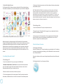
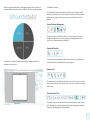
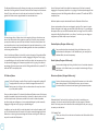
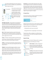
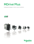
1.4 Available Digital Content
The Silhouette Studio® software comes pre-loaded with 50 ready-made designs.
These become available as you connect and power on your electronic cutting tool.
E
L
P
M
SA
Pre-loaded shapes will vary between Silhouette electronic cutting tools.
Additional content is available through the Silhouette Online Store (accessed
through the Silhouette Studio® software). The online store will allow you to access
and purchase additional digital content for the software, available both from
Silhouette America artists as well as independent artists and various companies,
thus ensuring a variety in look and feel of available pre-made content. Further
information on the store and downloading content will be provided later in this
manual.
2. Installing Silhouette Studio®
2.1 Installing on PC
1. Insert the installation CD into your computer’s CD-ROM drive.
2. Windows Vista,Windows 7, and 8 users: You may need to allow permission
to run the installer program that is automatically launched, or select to Run
SilhouetteInstaller.exe if given the option to do so.
3. When the installer is launched, click Next to proceed.
4. The license agreement will then be displayed. Carefully read and review the
information provided and then click on Yes to continue the installation process.
4
5. Continue to follow the prompts to install to the desired directory and complete
the installation process.
NOTE FOR WINDOWS USERS ONLY: Upon hooking up the USB cord from the Silhouette
electronic cutting tool to your computer and powering on the Silhouette unit, you may
be prompted with a “New Hardware Wizard” to install a driver. You may proceed to
automatically find and install the driver as located on the installation CD. The driver is not
required for proper operation of the Silhouette Studio® software, but may be installed to
resolve the Windows automatic “Plug and Play” feature of prompting to install a driver for the
hardware whenever the Silhouette is powered on.
2.2 Installing on Mac
1. Insert the installation CD into your computer’s disc drive.
2. Drag and drop the Silhouette Studio® program into your Application folder to
launch the installation process.
3. As the program is initially launched, the license agreement will be displayed.
Carefully read and review the information provided and then click on Yes to
continue to complete the installation process.
3. Basic Software Overview
3.1 Opening the Software
To open the software on PC, locate the desktop icon and double-click. If a desktop
icon was not created during installation, go to the Windows Start menu and select
to run Silhouette Studio®.
To open the software on Mac, open the Applications folder and launch Silhouette
Studio®.
The Silhouette Studio® icon will appear as follows:
When you open Silhouette Studio, a homepage will appear that will allow you to
navigate to different locations within the software. Click Design to begin designing.
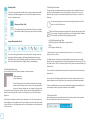
3.2 Software Sections
The software offers several sectioned areas. Details as to each button’s specific
function are discussed in later sections. However, so that you may be familiarized
with where everything is located, a brief overview is provided for each of the
sections.
General Document Management
This section along the top left-hand side of the screen is for general document
management functions, such as opening, saving, and sending documents to a
printer or your Silhouette electronic cutting tool.
Standard Editing Tools
Once opened, the software should show an available starting document and
workspace as shown below:
This section along the top left-hand side of the screen is for basic copy/paste/cut
and undo/redo actions commonly found in many programs.
Zooming Tools
This section along the top left-hand side of the screen is for basic zoom-in or zoomout functions to view parts of the document from a closer perspective or at a more
distant range.
Silhouette Studio® Tools
This section along the top right-hand side of the screen provides a range of tools
for filling images, altering lines, adjusting text attributes, adjusting and replicating
images, and adjusting page and cutting conditions.
5
Drawing Tools
This section along the left-hand side of the screen provides tools used for
selecting, and drawing images as well as the ability to drop text directly
into your workspace area.
Library and Store Tools
This section along the left-hand side of the screen provides
tools used for accessing the library and online store section.
Image Manipulation Tools
This section along the bottom of the screen provides a range of tools for
grouping and selecting images, duplicating and deleting items, image
placement priority (such as bringing images to the forefront or sending
them to the back behind other images), welding, and offsetting.
3.3 Cutting/Drawing Area
You will note there are two different sections in your workspace:
• White workspace
• Grey holding area
The white workspace notes the active document area. Images
may be placed or drawn onto this area, or they may be placed
or drawn in the grey holding area. Any images in this grey area
are invisible to your cutting tool or printer. You may wish to place images off to the
side to be set aside as you do not wish to include them in your job to be printed
and/or cut.
You will note a red border inside this white workspace. The red line represents the
active cutting area. The cutting tool will only be able to see and be able to cut what
is inside this red line. All images being sent to the Silhouette to cut should be within
this red line area.
6
3.4 Opening Documents
Though opening the software will always provide you with a new document, you
may select a new workspace to start a new project at any time. To start a new
document you may either use the New option from the File menu, or select the
New icon:
To open existing files you may either use the Open option from the File
menu, or select the Open icon:
You will then be prompted to navigate to the location where your desired
file is located. Through the Open feature, the Silhouette Studio® software
has the ability to open the following cutting-type files:
• STUDIO (Silhouette Studio® files)
• GSD/GST (Graphtec “ROBO Master” program files)
• DXF *
• SVG (Designer Edition only)
* Silhouette Studio® supports the following DXF features only: Arc, Circle, Ellipse, Line,
DWPolyline, Spline, and Text
The Open feature can also access simple image file types that are not in cutting
format, but may be imported for printing or tracing purposes. When using a PC, you
will need to select “All Files” under the type of file as you seek to open another type
of file format.
A list of recently used documents may also be accessed from the File menu under
Open Recent.
You may also use the Merge option from the File menu to open any file into the
same workspace you are using rather than opening a new document workspace.
Finally, compatible file types may also be accessed by dragging the saved file from
your computer directly onto your workspace in the software.
3.5 Document Tabs
Each new document or opened document will provide you with a new document
tab at the bottom left hand corner of your screen.
The tab will be labeled as “Untitled” until you save your file with a name, or if you
have opened a file that already had a name, in which case the file’s name will be
displayed. The white tab will always be the active document while all other opened
inactive documents will be grey. You may click on any inactive tabs to make it the
active workspace and toggle between open documents. Clicking on the “X” will
close any open workspace.
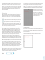
As you slide the bar to the right or increase the percentage number, the white page
workspace will become more transparent and show the cutting mat beneath. A
setting of 100%, or having this bar slid all the way to the right, will allow you to see
the cutting mat completely and your white workspace will be entirely transparent.
When viewing in this manner, the red line
will still represent your cutting area. Images
falling outside of this red cutting area will
not be cut. The darker area on the cutting
mat represents your printer’s print margin
area and is only for reference.
3.6 Document Sizes
When a new document is opened, the default document size will always start at
a standard Letter size (8.5” x 11”) for the original Silhouette, Silhouette SD, and
Silhouette Portrait® models or a 12” x 12” size for the Silhouette CAMEO® model.
To adjust your document size to another setting, you may either use the
Page Tools option from the View menu, or select the Page Tools icon:
The Page Tools will allow you to alter the width or length of your document. There
are pre-set common sizes you may select, or you may set measurements manually
for any custom page sizes of material you may wish to use.
With custom page sizes the width may be adjusted up to a maximum 8.5 inch
material width (original Silhouette, Silhouette SD, and Silhouette Portrait®) or a
12 inch width (Silhouette CAMEO®) depending on the cutting model used. The
minimum recommended width for a custom size is 3 inches. The height may be
adjusted up to any desired measurement. However, the maximum recommended
height is 40 inches. While longer materials ranges may be selected, lengths
exceeding 40 inches may have the possibility of becoming misaligned on the
Silhouette machine’s rollers as the cutting process continues beyond this maximum
recommendation. The minimum recommended height for a custom size is 3 inches.
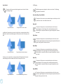
3.7 Cutting Orientation
Documents may be viewed in Landscape or Portrait orientation. Depending on how
you may wish to view your workspace, images being sent to the Silhouette will vary
based on your orientation.
Landscape is the default orientation whenever a new document is opened.
While viewing the Page Settings menu, if your material is sized to fit onto the cutting
mat, the cutting mat will be displayed to help you see how your material may be
placed onto the cutting mat to feed into the Silhouette when it is time to cut. Later,
as you go to cut, this will also be displayed to help ensure you are feeding your
material into the Silhouette correctly. This cutting mat animation may be selected to
always be displayed under the Preferences settings (discussed in section 3.9).
When the cutting mat is shown, you may select the Reveal Cutting mat option in the
Page Settings menu in order to show exactly on your mat where images will be cut
in reference to the grid that is printed on the actual cutting mat.
7
When a document is in landscape orientation, it will be sent to the Silhouette with
the upper left-hand corner of the screen coinciding with the upper right-hand side
of your material, as seen below:
3.8 Viewing and Zooming
Often as you view your workspace, you may either wish to zoom in to get a closer
look at smaller images or parts of an image that may be more difficult to work with.
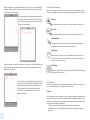
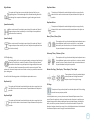
Portrait orientation is an optional orientation that
may be switched to through the Page Tools. Using
this orientation will provide you with a screen that
appears as the following:
Zoom In
This tool will zoom into the center of your workspace for a closer view.
Zoom Out
This tool will zoom out from your view for a more broad perspective.
Selection Zoom
This tool will allow you to zoom to specific areas of your workspace by
drawing a box around the area you wish to zoom into.
Drag Zoom
After clicking on this tool, your icon will appear as the Drag Zoom icon
above. You may then click and hold down your mouse to zoom in or out
manually to any selected scale.
When a document is in portrait orientation, it will be sent to the Silhouette with the
upper right-hand corner of the screen matching the upper-right hand side of your
material, as seen below:
The Page Tools also provides the ability to rotate how
you are viewing your page. While the Page Orientation
will dictate the way your cutting job is being sent to
the Silhouette to cut, the Rotate View option will
simply rotate your workspace on the screen for a
different perspective.
Fit to Page
Clicking the Fit to Page icon will immediately fit the full defined workspace
to the center of your screen.
3.9 Preferences
There are a number of user-controlled options that may be found in the File menu
(PC) or Silhouette Studio® menu (Mac) under Preferences.
General
This section allows you to manually select the program language and how often you
may wish the program to check for available software updates automatically. This
section also provides preferences regarding units of measurement displayed in the
program. You may adjust the following:
• Unit of Length – Adjust all displayed measurements to desired unit.
• Dimensions – Turn on or off image’s measurement properties as images are
selected.
8
Defaults
Import Options
This section will allow you to adjust the default settings when Silhouette Studio®
software is opened. You may adjust the following settings:
Allows you to determine the behavior of various file types when opened.
• Default Fill Style – Provides the ability to select how new user-drawn images
are created as to whether they are displayed as an outline only (as red line
images or grey line image), or as solid fill images (which may be preferable for
the creation of print & cut images that are made by the user).
• Registration Marks Preference – Adjusts the program to default to have
registration marks turned on or off.
• Page Orientation – Define whether Landscape or Portrait orientation is desired
whenever a new document is started.
• Blade Type – Defines which cutting blade is being used with the Silhouette.
• Page Border – Gives the option to cut to the edge of your page.
Display
This section provides display options including:
• Anti-aliasing – Helps smooth jagged lines as they are created and viewed.
Higher sample rates will increase the smoothness of lines. The “off” setting will
produce rougher edges, but increases drawing speed.
• Button sizing – Allows for larger or smaller buttons to be displayed.
• Animation – Controls speed of animating actions, such as images being moved
on undo or redo actions, or during zooming in and out. Can be adjusted to
“Instant” to turn animations off.
Selection
This section provides preferences for adjusting how the program selects images or
how various drawing tools either continue to draw or finish upon completion of
using the drawing tools.
Silhouette Devices
Controls how Silhouette models are detected when connected to the computer.
Advanced
This section provides additional advanced options. In this section, you may adjust
the following:
• Restore Factory Defaults – Resets all preferences.
• Reindex My Library –Performing this action will re-index the library to ensure
corruption or errors may be resolved should you experience any concerns with your
library loading properly or being able to use the library’s Search function properly.
• Set Library Permissions – Allows library to be properly accessed according to
computer account permissions.
• Restore Pre-loaded Designs –Restores pre-loaded designs according to the
Silhouette model detected.
• Reset Library – This action will remove all images and folders from your library
and reset the library back to its original software installation settings.
• Background Color Preference – Allows you to determine the color of the
inactive workspace area.
• OpenGL Settings – Attends to select display issues.
• Curve Quality – Enhances the visual appearance of lines on screen. Does not
affect actual cut quality.
• HTTP Sockets – Depending on your internet connection speed, this option may
be adjusted to a higher number of sockets to increase the download speed when
purchasing images from the online store.
Editing
• IME Setting – Allows for typing of non-western characters.
This section provides preferences for how you may wish to view bezier control
handles and how you would like images to behave when certain modifications are
applied.
• Proxy Settings – Used for proxy connection setups.
• Packet Size – Rate at which information is sent to the Silhouette.
9
Another program option not in the Preferences menu is the Software Color
Theme button located in the bottom right-hand corner of the software
screen.
Clicking on this button will cycle through a pre-selected list of color themes for the
software’s overall appearance, should you prefer some color other than the default
dark grey interface.
4. Drawing/Editing Images
4.1 Basic Drawing Tools
Silhouette Studio® allows users to draw and create images very easily through a set
of basic drawing tools. All drawing tools are located on the left side of the software
screen.
Line Tool
The Circle Tool allows for the creation of an oval or circle. Holding down
the Shift key on your keyboard while drawing will create a circle, while
holding down the Alt key on your keyboard will make the initial cursor
point where your image is started as the exact center of your object.
Polygon Tool
The Polygon Tool allows for the creation of multiple straight lines. A point
will be created upon each mouse click. Lines will continue to be drawn
until the image is closed by aligning the end point with the starting point,
or by double-clicking the mouse to stop drawing. Holding down the Shift
key on your keyboard while drawing will force a straight vertical, horizontal, or
45-degree increment line from the start point or last point dropped.
Curved Shape Tool
The Line Tool allows for the creation of single straight lines. Holding down
the Shift key on your keyboard while drawing will force a straight vertical,
horizontal, or 45-degree increment line from the start point.
Rectangle Tool
The Rectangle Tool allows for the creation of a square or rectangle.
Holding down the Shift key on your keyboard while drawing will create a
square, while holding down the Alt key on your keyboard will make the
initial cursor point where your image is started as the exact center of your
object.
Rounded Rectangle Tool
The Rounded Rectangle Tool allows for the creation of a square or
rectangle with rounded corners. Holding down the Shift key on your
keyboard while drawing will create a rounded square, while holding down
the Alt key on your keyboard will make the initial cursor point where your
image is started as the exact center of your object. As a rounded rectangle is
selected, you will find two red control points on the rectangle’s upper left-hand
corner. These may be dragged to adjust the curves of the rectangle’s top and
bottom or sides, or you may select both simultaneously by holding down the Shift
key on your keyboard and dragging one of the control points.
10
Circle
The Curved Shape Tool allows for the creation of multiple curved lines. A
point will be created upon each mouse click. Lines will continue to be
drawn until the image is closed by aligning the end point with the starting
point, or by double-clicking the mouse to stop drawing.
Freehand Tool
The Freehand Drawing Tool allows for the creation of a continuous
free-form line. Lines drawn with this tool will continue until the mouse
button is released, or the image is closed by aligning the end point with
the start point.
Smooth Freehand Tool
The Smooth Freehand Drawing Tool allows for the creation of a smooth,
continuous free-form line. Lines drawn with this tool will have smooth
transitions and no sharp angles. Lines drawn with this tool will continue
until the mouse button is released, or the image is closed by aligning the
end point with the start point.
In Point Editing Mode, you will also be shown the Point Editing toolbar on the righthand side of the screen. You may do the following actions in Point Editing Mode:
4.2 Editing Images
All line points on images may be edited, if changes to the existing image are desired.
Move/Adjust Points
Select Tool
Move a point by hovering with your mouse over any point on the line. Once over
a point that may be edited, the cursor will adjust to show you may click and grab
the point to move it to any desired location. With curved lines, you may similarly
grab the blue points and drag them around the screen to adjust the curve of the
associated line segment.
The Select Tool determines which image is selected as the active image
and allows you to move images around on your screen. This is your
default tool to click on images to show they are selected.
Edit Points
Add Points
To enter the Point Editing Mode, you may either double-click on a
selected image, or use the Edit Points tool. This tool will allow you to edit
any points of your image to move them around or remove them. Only
single ungrouped line selections may be edited. Ungrouping will be
discussed in later sections.
Add a point by hovering over the line where no points currently exist where you
may wish to drop a new point to edit your image. Once over a line where a point
may be dropped, the cursor will be adjusted to show you may click to drop a point
onto the desired line location.
To exit the Point Editing Mode, you may double-click on your image again, or return
to the regular select mode by clicking on the Select tool.
Point Editing Mode
When you enter the Point Editing Mode, selected images will change from
displaying the resizing and rotating control handles around the image to showing
the points, or nodes, of the image. Points on lines are where the line may take a
new direction or change from being flat (or straight) to being curved.
Delete Point
Any selected point will be deleted by using the Delete Point tool, or by
right clicking on the selected point and choosing the Delete Point option.
Deleting a point will cause the closest points on either side of the deleted
point to join and create a new connecting line. Note that this tool is
different from deleting an image and is only intended to delete individual points. It
will only be available while in Point Editing Mode.
Break Path
You may break the path of any line point by using the Break Path tool, or
by right clicking on the selected point and choosing the Break Path option.
Breaking a path will create two new points from the originally selected
point where the path was broken.
You will note that a broken path, or two unconnected end points of opposite ends
of the same line, may be re-joined by dragging one end point onto the opposite end
point of the image.
Regular Selection Mode
Point Editing Mode
In Point Editing Mode, the selected point will be displayed in white while all other
points will be dark grey. The selected line associated with the selected point will be
emphasized as a bolded red line. Additional lines that have blue points are handles
to adjust curved lines.
Corner
The Corner tool will allow a selected point to be so that the control
handles at the selected intersecting point can be adjusted each
individually to create a sharp corner.
11
Smooth
Knife Tool
The Smooth tool will allow a selected point to be adjusted to make a
smooth transition point at the selected intersecting point.
Make Flat
You may segment images using the Knife tool. This tool delivers a straightline cut to separate parts of images to create a new separate independent
shape. The Designer Edition of the software features several options for
knife path shapes and allows you to choose between creating an open or closed
knife path.
The Make Flat option will adjust the selected line (the line emphasized in
bold red that is associated with whichever currently selected point) to a
flat, straight line.
Make Curve
The Make Curve option will adjust the selected line (the line emphasized
in bold red that is associated with whichever currently selected point) to a
curved line.
Simplify
Some library images or other imported images from other sources may
contain a very large number of points. The Simplify tool will automatically
re-adjust the image’s points and simplify the image to its simplest possible
point form while maintaining the image’s original overall line form.
Aside from the tools found in Point Edit Mode, there are two additional editing tools
found on the left-hand side of the screen.
Eraser Tool
You may erase any part of any image using the Eraser tool to easily and
immediately remove inner parts or edges of the line image. The Designer
Edition of the software features several options for eraser shapes and
allows you to choose between creating an open or closed eraser path.
12
Original Image
New Image Using Eraser Tool
New Image Using Eraser Tool
4.3 Line Tools
Lines in the program, including text, images created using the drawing tools, and
library images, may be altered to have different properties.
Line Color Options
While lines will default to be displayed in red, you may alter lines to any
desired color. Altering line colors will not affect their properties in how
they may cut. Altering line colors may be helpful to allow you to more
easily view different images or image parts, see lines in whichever color you may
prefer to view them, or adjust image parts specifically with printing in mind for print
& cut jobs where it may be important that line colors are selected to be printed.
To adjust line colors, select your image and access the Line Color menu by clicking
on the icon shown above. You may then select any of the Basic Menu color options.
The hash line selection will always represent “clear”. The color picker tool will allow
you to select any color from another object in the drawing area to duplicate the
desired color.
Clear
Original Image
Color Picker
The Advanced Options menu will allow you to create lines in any desired custom
color. You may either drag the target on the color spectrum to visually match
the color you are looking for, or type in the RGB (Red Green Blue) or HSL (Hue
Saturation Lightness) value of your desired color. You will also have the ability to
adjust the Transparency of the line.
Line Style Options
Within the Line Style menu, you may adjust the style of your line to be a
solid (default) or dashed style line. Lines will accordingly be cut or printed
in the selected style.
Lines are viewed in point sizes regarding their width. The point size may be adjusted
to any desired specification. While line width may be adjusted, the line will always
be cut or sketched in a fixed width; that is, according to how thick the blade or pen
is that you are using.
Line thickness may be adjusted by either manually dragging the Thickness option
bar or by typing in the desired point thickness.
The Corner Style option will adjust how lines appear at any of the image’s corner
points where Corner is a sharp edge whereas Rounded will be a smoother edge.
The End Cap Style option will only adjust lines that have open ends. Flat or Square
provide varying sharper flat edges at the line tip whereas Rounded provides a
smoother rounded edge to the line tip.
The Position option will adjust if the line is In Front of a filled image, or Behind the
filled image.
If you desire to send your document to a printer to print your images, the Print
Lines of Selected Shapes option will enable all lines of selected images to be printed
as they appear on the screen.
4.4 Fill Tools
Closed images (where the starting point of the line connects with the ending point
of the line) including Text, images created using the drawing tools, and library
images, may be altered to have different filled properties. Only closed images may
have filled attributes. If the path is broken on any closed images, any applied fill
attributes will immediately disappear.
Fill Color Options
While closed images will default to be displayed as empty, you may fill any
closed image with any desired color. Altering fill colors may be helpful to
allow you to more easily view different images or image parts, see shapes
and text in whichever color you may prefer to view them, or adjust images
specifically with printing in mind for print & cut jobs.
To apply fill colors, select your closed line image and access the Fill Color menu
by clicking on the icon shown above. You may then select any of the Basic Menu
color options. The hash line selection will always represent “clear”. The color picker
tool will allow you to select any color from another object in the drawing area to
duplicate the desired color.
Clear
Color Picker
The Advanced Options menu will allow you to create fill colors in any desired
custom color. You may either drag the target on the color spectrum to visually
match the color you are looking for, or type in the RGB (Red Green Blue) or HSL
(Hue Saturation Lightness) value of your desired color, if you are seeking a specific
known color. You will also have the ability to adjust the transparency of the filled
color by manually dragging the Transparency option bar or by typing in the desired
percentage of how transparent you wish the filled color to be, where 0% is solid and
100% is completely clear.
Fill Gradient Options
Similar to filling images with solid colors, you may also select to fill any
closed line images with a gradient fill.
To apply gradient fill options, select your closed line image and access the Fill
Gradient menu by clicking on the icon shown above. You may then select any of
the Basic Menu pre-created gradient options. The hash line selection will always
represent “clear”.
Clear
You may also alter the basic direction of the gradient by clicking on any of the
Direction options at the bottom of the Basic Options panel.
13
The Advanced Options menu will allow you to create your own custom gradient fills
based off of the last gradient fill selected. Gradient fills will always have a minimum
of two (2) colors, with one color at the top and one color at the bottom. The
gradient will then create a range between the two selected colors.
You will also have the ability to adjust the transparency of the line by manually
dragging the Transparency option bar or by typing in the desired percentage of how
transparent you wish the filled gradient effect to be, where 0% is solid and 100% is
completely clear.
Additional patterns may be downloaded from the Silhouette Online Store.
You may change either of these colors in the range by clicking on the color arrow
bars on the left-hand side of this gradient creator tool. Once the color is selected,
you may then select any new color from the Select Color tools directly below. You
may also add new bars at any interval between the top and bottom colors, or slide
any color bars in between the top and bottom gradient color bars up and down to
create new gradient effects.
Also in the Advanced Options is the ability to rotate the angle of the gradient effect
to any customized degree by either manually dragging the Angle tool or by typing
in a specified degree. You will also have the ability to adjust the transparency of the
line by manually dragging the Transparency option bar or by typing in the desired
percentage of how transparent you wish the filled gradient effect to be, where 0% is
solid and 100% is completely clear.
Fill Pattern Options
You can create patterns from your own images by going to File > Import > Import
Options. Navigate to the image you would like to use and select it. A new dialogue
box appears where you can add information about the image. Press OK to add the
image to the My Own Design folder in your library. From there, you can drag your
image onto any fillable shape on your workspace.
Shadow Options (Designer Edition only)
You can add and adjust a shadow by clicking the Shadow icon in the
toolbar above the workspace. In the Shadow menu, you can adjust the
shadow offset, color and transparency.
Sketch Options (Designer Edition only)
Create a sketch design by clicking the Sketch icon in the toolbar above the
workspace. In the Sketch menu, you can adjust the sketch edge, fill type,
and fill effect.
Rhinestone Options (Designer Edition only)
Create a rhinestone design by clicking the Rhinestone icon in the toolbar
above the workspace. In the Rhinestone menu, you can choose a
rhinestone effect, rhinestone size and spacing, and placement options.
The final fill option is used to fill any closed line images with a pattern fill.
To apply pattern fills, select your closed line image and access the Fill
Pattern menu by clicking on the icon shown above. You may then select
any of the pattern options.
Once your desired pattern fill is selected, the Advanced Options menu will allow you
to adjust the pattern’s direction Horizontally or Vertically, or adjust to either a Fixed
or Stretch aspect ratio. Options are provided in this menu to rotate the pattern
by either simple pre-set degrees, or to any customized degree by either manually
dragging the Angle tool or by typing in a specified degree.
In addition, you have the ability to scale the pattern’s size to alter the pattern itself
as it fills the selected shape. You may do this by either manually dragging the Scale
Pattern bar or entering a new percentage value of how much larger or smaller you
may wish to make the filled pattern.
14
5. Text
Silhouette Studio® has the ability to utilize any font that is installed on your
computer. You do not need to install these fonts into the program. Silhouette
Studio® will simply access all installed font files and display them for you as you go
to create your desired text.
5.1 Creating Text
To use your fonts, click on the text tool located on the left-hand side of the
software screen.
Clicking this will allow you to place a text cursor onto your workspace and begin
typing directly onto the screen.
The red blinking line is your cursor to show where you are typing. You may back up
or move forward by either clicking your mouse or using your computer’s right and
left arrow keys.
The surrounding green box is your text box. This box may be adjusted by clicking
and holding the black bar on the right edge of the text box. Dragging this bar to the
left will allow you to wrap your text. Dragging this bar to the right will allow you to
bring text back toward being on a single linear path.
You may double-click or click outside of the text to exit the Text Editing Mode. You
may return at any time to re-edit any words or letters by double-clicking again on
your created text.
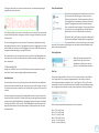
Font Characteristics
Some fonts are programmed to enable the use of certain
style characteristics allowing you to bold, italicize, or
underline text or letters. These characteristics will only
be highlighted to be available for selecting if the font in
question is programmed with that characteristic and
such characteristics can be applied. To apply one of these
characteristic, you may highlight the intended letters or
words and then click on the available characteristic.
While Bold, Italic, and Underline options are displayed, if
there are any additional available options programmed
for the selected font, a scroll bar will appear on the righthand side of this option box allowing you to scroll down and view whatever other
options may be programmed.
Text Justification
While text will be automatically be
justified to the left, if your text is
wrapped on multiple lines, you may
alter your text justification as desired.
5.2 Manipulating Text
During the creation of your text, the Text Style menu will be opened on the righthand side of your screen providing multiple adjustment options.
Available Fonts
The first section of this menu will display the current selected font with additional
font options that are installed on your computer you may scroll through. The top of
this section may be used to search for any specific font by typing in a font name if it
is known.
You may change fonts during the Text Editing Mode and use a new font within the
same text box with other fonts. Different fonts may also be applied to existing text
or letters during Text Editing Mode by highlighting the desired string and selecting
the newly desired font. If you are not in Text Editing Mode, new fonts may still be
applied to selected text, but such adjustments will change the font for the entire
selected text box.
Text Size
Text size will always default to 72 point size. This refers to the font’s printed font
size. Though fonts vary as they are programmed by a wide variety of sources,
this will generally equate to roughly a one (1) inch height (or 25 mm). The most
common point sizes for print-format fonts are included in the available drop-down
list, though any custom number may be manually typed into this size preference.
Other common equivalent measurements in the list include:
18 pt = 0.25 inch (6 mm)
24 pt = 0.33 inch (8 mm)
36 pt = 0.5 inch (13 mm)
48 pt = 0.66 inch (17 mm)
144 pt = 2 inches (50 mm)
288 pt = 4 inches (100 mm)
15
Again, these measurements are approximations and will vary from font to font, so
if you are seeking to obtain a specific measurement, you may wish to alternately
re-size your text to your desired specification after creation.
As text is applied to a path in this manner, you will note a vertical bar to the left
of the text. This allows for a new control bar which can be used to adjust the
placement of your text relative to the line onto which the text has been applied so
that it may be placed on, above, in line with, or below the path.
Character Spacing
Note also that the object used as a path will turn grey. This indicates that this image
is now turned off for cutting purposes. If you wish to re-enable the object being
used as a path to cut, you may visit the Cut Style Options as previously discussed
and select Enable Cut Style as the grey path object is selected.
Letters may be adjusted from their normally programmed spacing to either bring
them closer together or push farther apart with the Character Spacing option.
6. Manipulating Images
Spacing will always start at 100% indicating spacing between characters are
normally distanced. As the number is lowered or the bar is slid to the left, letters
will come closer together. As the number is raised or the bar is slid to the right,
letters will become spaced farther apart.
Line Spacing
If your created text is wrapped to multiple lines, you may similarly increase or
decrease the Line Spacing option to adjust the distance between lines of text.
Spacing will always start at 100% indicating spacing of lines are normally distanced.
As the number is lowered or the bar is slid to the left, text lines will come closer
together. As the number is raised or the bar is slid to the right, text lines will
become spaced farther apart.
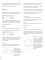
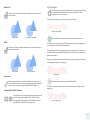
5.3 Text to Path
As text is created, or while in Text Editing Mode, you will find a control
point located on the left-hand side of the text being created:
This control point may be
dragged to rest directly on any
line path within your workspace.
For example, you may create an
oval with the Circle tool and then
drag your text onto this line to
achieve an arced effect:
16
There are many tools in Silhouette Studio® allowing for basic and advanced
manipulation of images and text. The following section provides an overview for all
of these included tools and how they may be used.
6.1 Basics
Like most any software program, Silhouette Studio® has a set of common basic
editing tools as follows:
Selecting
Images may of course be selected by clicking on them. Multiple images may be
selected by holding down the Shift key on your computer keyboard and clicking
on another image. You may repeat this action to select as many images as desired.
Holding down the Shift key and clicking on an image that is already selected will deselect that image.
Multiple images may be also be selected
by clicking above an image and dragging
your mouse to enclose all desired shapes
to be selected at the same time. As you
hold your mouse button down and drag
your mouse, you will see a dashed line
creating a selection box showing what
you are selecting. Upon letting go of your
mouse, all enclosed images in this box
will be selected together in the same
bounding box.
If you wish to select all available images on the screen together, you may
click on the Select All button located along the bottom of the software
screen.
If you wish to select only those images that are the same color, you may
click on the Select by Color button located along the bottom of the
software screen.
If you wish to deselect all currently selected images, you may click on the
Deselect All button.
Copy/Paste/Cut Tools
These tools perform the basic expected actions of copying
selected images, pasting them, or cutting them from view.
Images copied or cut will reside in your computer’s memory on
a virtual clipboard. You may only have one object on this clipboard at a time. This
means if you copy one image and then copy another, only the most recent image
will be waiting on the clipboard to be pasted. These actions may be accessed from
the top tool bar, in the Edit menu, or by right-clicking on an image, as well as by
using standard shortcut keys for these actions.
Pasting copied images will place the copy directly to the right of your original image
so you may easily see and find your copy. An additional Paste in Front option is
also provided to be able to paste a copy of an image directly on top of itself and is
found in the Edit menu, in the right-click menu for the selected image, or by using
standard shortcuts for this action.
Duplicate
The Duplicate option performs the same action as copying and pasting the
selected image to the side, but does so without the need of utilizing your
clipboard and is a one-click operation. This toolbar button is located along
the bottom of the software screen and can alternately be located in the Edit menu
or by right-clicking on a selected image.
Undo/Redo
Any action taken, including simply moving an image, may be undone.
To back up to the previous action taken, click the Undo button. There
are an unlimited number of actions you may go back to with the
Undo button, including going back to when you first opened your new workspace.
Similarly, you may click the Redo button to repeat any actions you may have
undone. You may continue to use this button until you return to the last action
taken.
Transfer Properties (Designer Edition only)
Properties such as line color and cut style can be transferred from one
shape to another by selecting the shape you want to transfer properties
to, selecting the Eye Dropper icon in the toolbar below your workspace,
and then clicking on the shape you want to imitate.
Layers (Designer Edition only)
When you import a project with layers created in another program, you
can access those layers in the Layers panel. You can also the +/- keys to
add or remove layers in Studio.
6.2 Grouping/Ungrouping
These two actions are commonly used and are invaluable tools for helping to
manipulate and adjust images. To understand these concepts we must first
understand what grouped and ungrouped images are.
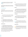
The following is an example of a single line:
While the image may have many parts, it is still just one
line with a single starting point and end point.
Delete
Selected images may be deleted from your workspace by clicking on the
Delete button located along the bottom of the software screen, by
accessing the Edit menu and selecting Delete, right-clicking a selected
image and choosing the Delete option, or by simply pressing the Delete key on your
computer keyboard.
17
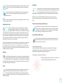
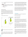
The following is an example of a multiple line image:
This image has two line sets with the body of
the leaf and stem being one part and the inner
details of the leaf being another. This image is
grouped together so that if moved around on
your screen, you do not have to move the outer
line of the leaf and then move the center part
independently and try to align it inside.
6.3 Compound Paths
The concept of compound paths is important in order to understand why certain
attributes may be applied differently to seemingly identical situations. Compound
paths are a collection of two or more line sets where inner lines are embedded into
the image. A compound path may appear the same as a grouped set of lines, but is
quite different in the way it will react to being filled with color, for example.
Compound paths are only really a concern when you are creating print & cut
images.
While it is not necessarily important to know exactly how many line parts an image
has, it is important to understand that single line images are not grouped together
with anything, while anything that has multiple parts is or can be grouped.
Grouping
Any two sets of lines can be grouped together so they are fixed in their
relative positions, even if moved, by using the Group option.
To use the Group option, select two or more images at the same time and click on
the Group icon located along the bottom of the software screen. This can alternately
be located in the Object menu or by right-clicking on the multiple selected images
and selecting Group.
Ungrouping
Any image that contains more than one line set can be ungrouped so that
parts of the image may be treated independently, removed, rotated,
resized, or otherwise manipulated rather than having to manipulate the
image as a whole.
For example, you may wish to cut out this cake image, but want to ungroup the
image in order to remove some of the inner decorations of the image:
Once ungrouped, the image will be displayed
showing individual selection boxes around
each new ungrouped image part that can
now be manipulated:
To access the individual ungrouped parts,
you may unselect your image and then
click onto any independent desired part for
further removal or manipulation.
18
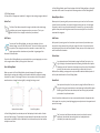
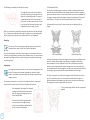
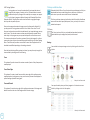
Non-compound Image
Compound Path Image
In the previous examples, the top two images are seen straight on and appear to be
identical. However, when looking at the bottom set of images the differences
become apparent. With the image on the left, from a side view we are actually
looking at a grey butterfly with white spots resting on top. This is an image that is
not a compound path. With the image on the right, from a side view we see that we
are looking at a grey butterfly with white spots embedded into the image.
Of course, as we go to cut or sketch both images with the Silhouette, they will cut
out in the exact same manner, but it is important to understand that there is a
difference between these images as you may wish to achieve certain effects with
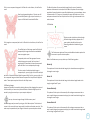
filling images for print & cut applications. For example:
This is the same image unfilled. All parts are grouped
together.
If this is a non-compound image and it is filled with a color feature, this will be the
result:
Even though grouped together, all line sets are still
just individual pieces lying on top of each other, so
they are all filled with the selected fill effect.
The Move By option will move selected images from the current location by
whatever measurement is entered, while the Move To option will move images
regardless of present location to a specific plotted course on your workspace, where
a measurement of 0, 0 (zero, zero) represents the upper left-hand corner of your
workspace and moves out from that point either to the right or downward as the
values increase.
6.5 Rotating
Objects may be rotated to any desired angle.
Selected images will always appear with a
green rotation handle-bar that may be
manually grabbed and rotated using your
mouse.
If this image has a compound path and it is filled with a color feature, this will be the
result:
The unfilled parts of the image cannot be filled with
compound path images because these embedded
areas are negative space.
Compound paths can still be ungrouped to move
multiple image parts around, but the action of
ungrouping will immediately release the compound
path and make it a non-compound path image
To make a series of multiple selected images a
compound path, you may right-click until the multiple
parts are all selected and select Make Compound Path. Similarly, you may right-click
on a compound image and select Release Compound Path to perform the opposite
action. These options may also be found in the Object menu.
6.4 Moving Images
Images may obviously be moved by selecting them and then dragging them around
the screen with your mouse to any desired location. Selected image may also be
moved by using the arrow keys on your computer keyboard.
You may also move images through the Move menu panel.
Selected images may be moved by using any of the Move options. The directional
arrows in this screen will move images subtly in whichever direction you select. This
action may be repeated until your image is located on your workspace as desired.
The Rotate menu options will also provide additional rotation options for
more exact or specific rotation options.
Within the Rotate menu you may select any of the following options.
Rotate By
These options will rotate the selected image by the selected common angle from
the image’s current angle.
Rotate To
These options will rotate the selected image to the selected angle based on the
image’s original fixed 0° point.
Custom Rotate By
This option will allow you to either manually slide a degree measurement bar or
enter a specific degree measurement and apply to rotate the selected image from
the image’s current angle.
Custom Rotate To
This option will allow you to either manually slide a degree measurement bar or
enter a specific degree measurement and apply to rotate the selected image based
on the image’s original fixed 0° point.
19
Center of Rotation (Designer Edition only)
To adjust the point around which your shape rotates, you can adjust the center of
rotation. To do so, select the shape you want to rotate, press the letter ‘O’ on your
keyboard to display a small crosshair icon in the center of the shape. You can then
move the crosshair icon to the desired new point of rotation.
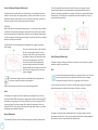
The Lock Aspect Ratio option when checked will ensure your image is resized
proportionately when only one measurement is being altered but you wish to
maintain the image’s proportions. For example, if we take our original leaf example
that started at 1 inch height by 2 inches width and adjust the width to 1 inch, you
can see the following results:
6.6 Sizing
Objects may be sized to any desired measurement. It is important to note, however,
that while you may customize images to any desired size, the quality of cuts made
may vary, especially when cutting thicker materials such as cardstock. Reducing the
size of an image with intricate parts and cutting it in a thicker material is an example
where the cut quality could suffer.
You will be able to view the measurement alongside your image as you draw or
select images.
There are also control points on the selection
box for resizing images manually. To resize
manually, simply click on any of these boxes
and drag your mouse in the desired direction
to make your shape larger or smaller. The
corner control points will proportionately
resize the image and maintain the relative
height and width, while the side control points
will stretch your image in the direction your
mouse is dragged.
The Scale menu options will also provide additional sizing options for
more exact or specific rotation re-sizing options.
Within the Scale menu you may select any of the following abilities.
With Lock Aspect Ratio
Without Lock Aspect Ratio
Shear (Designer Edition only)
Use Shear to skew your design vertically or horizontally. You can select from preset
amounts or specify a custom shear.
Grid
To assist with viewing measurements, you may also opt to turn on the grid
by either right-clicking on your workspace while there are no images
selected and clicking on Show Grid, or by going to the Grid menu.
In the Grid menu you may turn the grid on and off, adjust the grid spacing to any
desired measurement, and define the number of divisions in the grid.
Scale
These options will resize any selected images by a percentage of its current size.
Any number under 100% will make your image smaller and any number over 100%
will make your image larger. For example, selecting to resize your image to 50% of
the current size will make your image half as large while selecting to resize your
image to 200% of the current size will make your image twice as large. Any custom
percentage may be applied as desired.
Specify Dimensions
This option will allow you to resize a selected image to any specific measurement.
20
Single Division
Multiple Sub-Division
The Snap to Grid option when enabled will force the image to conform to grid’s
measurement and divisions. This may be especially helpful when drawing images to
force them to conform to specific desired measurements.
The grid’s Style may be selected to be either a traditional Square grid or an Isometric
grid. Again, the different styles may be helpful while drawing images within the
software to provide a reference for measurement as you draw.
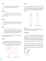
You may additionally create mirror copies of selected images with the Mirror menu
options, where you may create a mirrored copy to the left, to the right, mirrored
above, or mirrored below.
To mirror an image, you may right-click any selected image to select the Mirror
Horizontally or Mirror Vertically option.
Square Grid
Isometric
The grid’s Color can also be adjusted as desired and offers a pre-selected set of color
suggestions which may provide a non-intrusive appearance for your grid, though
any custom color may of course be selected.
Original Image
Mirror Copy Above
Mirror Copy Below
In Designer Edition, you also have the ability to activate Rulers and Crosshairs to
help make layout easier.
6.7 Mirroring
Some materials or situations require images to be cut in a mirror image format,
or you may simply want to flip objects around to achieve your desired image
appearance.
To mirror an image, you may right-click any selected image to select the Mirror
Horizontally or Mirror Vertically option.
Mirror Copy Left
Mirror Copy Right
6.8 Arranging
Multiple images may overlap each other. The order of which image is in front and
which is in back can be arranged. This is mostly used with filled images for print &
cut applications so you can determine which image should be in front of the other.
Bring to Front
No Mirror Effect
Mirrored Horizontally
Mirrored Vertically
Mirrored Horizontally and Vertically
This option will take your selected image and move it in front of all other
overlapping images.
Further mirroring options may be accessed in the Object menu under the Transform
sub-menu listed as Mirror Options.
In this menu, you may likewise flip your images around (as displayed above) under
the listed Flip menu options.
Original Image Order
Circle Selected and Brought to Front
21
Send to Back
6.9 Aligning
This option will take your selected image and move it behind all other
overlapping images.
Multiple images may be aligned in relation to each other. The following
Align options are available:
Centralize (Align Center-Middle)
This option will center two or more selected objects so that they are lined
up with each other in the middle of each other.
Align Left
Original Image Order
Triangle Selected and Sent to Back
In addition to these options, you may also right-click on an image and select Send
Backward to send the selected image one level back rather than all the way to the
back.
This option will align two or more selected objects so that they are
aligned together to the left edge of the shared bounding box while
maintaining their respective distances in regard to being above or below
each other.
Align Center
This option will align two or more selected objects so that their center
points are aligned together while maintaining their respective distances in
regard to being above or below each other.
Align Right
Original Image Order
Triangle Selected and Sent Backward
Similarly, you may right-click on an image and select Bring Forward to bring the
selected image one level forward rather than all the way to the front.
This option will align two or more selected objects so that they are
aligned together to the right edge of the shared bounding box while
maintaining their respective distances in regard to being above or below
each other.
Align Top
This option will align two or more selected objects so that they are
aligned together on the top edge of the shared bounding box while
maintaining their respective distances in regard to being next to each
other.
Align Middle
Original Image Order
22
Circle Selected and Brought Forward
This option will align two or more selected objects so that their center
points are aligned together while maintaining their respective distances in
regard to being next to each other.
Align Bottom
This option will align two or more selected objects so that they are
aligned together on the bottom edge of the shared bounding box while
maintaining their respective distances in regard to being next to each
other.
Space Horizontally
When a minimum of three objects are selected, this option will take all
images and space them horizontally so that all objects are equidistant
from each other horizontally.
Space Vertically
Duplicate Above
This option will duplicate the selected object and place a copy directly
above with the most minimal amount of space between the objects as
possible.
Duplicate Below
This option will duplicate the selected object and place a copy directly
below with the most minimal amount of space between the objects as
possible.
Row of Three / Row of Four
These options will copy the selected object and replicate two or
three additional copies next to each other in a row, stacked
horizontally next to each other, with the most minimal amount
of space between the objects as possible.
When a minimum of three objects are selected, this option will take all
images and space them vertically so that all objects are equidistant from
each other vertically.
Column of Three / Column of Four
6.10 Replicating
Replicating while similar to copying and pasting an image or duplicating it
allows for the ability to create any number of copies and place them at
once without the need to copy and paste the images multiple times and
then have to place them manually around the screen as desired. These
options will also create copies next to each other as closely as possible to maximize
your cutting area.
These options will copy the selected object and replicate two or
three additional copies next to each other in a column, stacked
vertically on top of each other, with the most minimal amount
of space between the objects as possible.
Rotate One Copy / Two Copies / Three Copies / Five Copies
These options will copy the selected object
and replicate one through five rotated
copies on top of the original image.
You will find the following options in the Replicate options basic menu.
Duplicate Left
This option will duplicate the selected object and place a copy directly to
the left with the most minimal amount of space between the objects as
possible.
Duplicate Right
This option will duplicate the selected object and place a copy directly to
the right with the most minimal amount of space between the objects as
possible.
Fill Page
This option will copy and replicate the selected object and fill the cutting
area with as many copies possible.
In the Replicate menu, you may also access an Advanced Options menu. Here
you will have the option to select any desired number of copies to replicate your
selected image and the distance between these replicated images, including the
ability to select any custom direction. Once the desired number of copies and
direction has been selected, you may click on the Replicate button at the bottom of
the Advanced Options menu to apply the selected attributes.
23
6.11 Nesting (Designer Edition only)
To minimize the space required to cut a certain design, the Nesting
feature can be used. You can choose to use your entire media surface to
nest you shapes or create a specific area for them to nest in.
Intersect
This option will leave only the overlapping part, or intersecting part, of
the selected images when applied.
Use Media
If you choose to Use Media, your entire media surface can be used to nest shapes.
Use Selected
If you would like to nest your shapes within a certain area, first draw that area on
your workspace. Next, click on Use Selected in the Nesting menu. Nesting will occur
within this defined area.
Select all the shapes you would like to nest. In the Nesting menu, you can adjust
the rotations and padding of the shapes to be nested. Increasing rotations and/or
decreasing padding will yield a tighter nest.
Original Image
With Intersect Applied
Subtract
This option will remove all overlapping parts of images that are in front of
other images, so that only the image located in back will remain with the
overlapping parts removed.
After making any necessary adjustments, click Nest and the shapes will nest
together to maximize space. If you have selected more shapes than will fit in the
nesting area, the software will determine which shapes fit best in the defined area.
6.12 Welding & Modify Options
Overlapping images may be altered in a variety of ways. The Modify menu
options provide welding and other advanced options to allow overlapping
images to be adjusted.
Within the Modify menu you may select any of the following abilities.
Weld
With Subtract Applied
Crop
While the Weld option may be found in the Modify menu, there is also a
quick access button located along the bottom tool panel of the software
screen. Welding will take two or more selected overlapping images and
join them together into one single continuous image.
Non-welded image with overlapping lines
This option will remove all areas that are not shared by at least two
shapes when overlapping.
Welded image with overlapping lines removed
Welding can be particularly useful when cutting so that the cut lines don’t overlap
during the cutting process.
24
Original Image
Original Image
With Crop Applied
Subtract All
6.13 Offset Options
This option will remove any portion of an image that is in back behind
another image.
The Offset option may be used to outline cut-line images giving the image
a shadowed mat effect underneath it. It may also be used to create
contoured inner lines for images.
To apply offset conditions, you will first need to select an image.
Original Starting Image
Original Image
With Subtract All Applied
Divide
This option will create individual images from the intersections of up to
eight selected images.
Within the Offset menu you may start by selecting the offset action.
You may select to either have your offset image have a sharper Corner appearance,
or have a softer more bubbly Round appearance.
Though clicking the offset action button provides a starting point, you may fine tune
the offset effect to any specified Offset Distance with the slider bar, or by typing in a
specific measurement.
At any point your desired effect is achieved you may set the properties of the newly
created image into place by clicking Apply.
Original Image
With Divide Applied
Offset Image
Detach Lines
When images are filled or have thick lines defined, this option may be
used to detach and move the outline to create two separate images; one
with just the lines and one with just the filled effects left behind.
Compound Paths (Make / Release)
These options are the same options previously discussed in the
section 6.3 regarding Compound Paths. This tool will take
overlapping embedded images and either Make them into a
compound path or Release the compound path.
You may conversely create an internal offset condition.
This feature is generally better suited for the creation of internal lines for use with
sketch pens.
Internal Offset Image
25
6.14 Tracing Options
Tracing options can be used to automatically trace imported external
images for the purpose of creating cut lines. Silhouette America cannot
guarantee the quality of images not created by our company nor support
any third-party images not offered through the Silhouette Online Store.
Silhouette Studio® should not be used to trace licensed or copyrighted images
which you do not specifically own.
Once you have opened an external image you own (as discussed in Section 3.4),
you may open the Tracing options and then click on Select Trace Area. This will
allow you to draw a box around the intended area of your imported image you may
wish to trace. This selection area once drawn may be adjusted or moved like any
other object in the program as you may need to expand or refine the trace area.
The trace area selection will provide a preview of the original image with a yellow
area overlay where the trace area would be applied according to the Trace Settings
filters. These filters will provide a more refined or more liberal application of the
intended traced effect depending on the settings selected.
Once the desired tracing effect preview is achieved, you may then opt to apply the
trace method by selecting one of the following:
7. Library and Online Store
Silhouette Studio® offers a library feature to keep and categorize all of your
downloaded and user-created image for easy reference, as well as an
online store to provide new content for users to download.
The library and store views may be found on the left-hand side of software
screen and show which panel (workspace, library, or store) is the current
selected active panel.
7.1 Library
The library is where all of your pre-loaded and purchased content is
contained and may be categorized, sorted, and accessed.
Viewing
You are able to view your images as icons by clicking on the Icon View
option:
Trace
This option will provide a traced line contour around all parts of the yellow preview
area displayed.
Trace Outer Edge
This option will create a traced line around the outer edge of the yellow preview
area displayed only and ignore any inner parts that may otherwise be displayed in
yellow showing a potential tracing path.
Trace and Detach
This option will trace the outer edge of the yellow preview areas of the image and
detach them from the rest of the background of the raster image.
Library in Icon View mode
You may alternately view your library images in a list view to see more
detail by clicking on the List View option:
Library in List View mode
26
In List View mode you may sort your images by Name, Category, Artist, Date
Downloaded, or Size by clicking on these column header titles.
In addition to how you view your library content, you also have the ability
to adjust how your library is viewed as to whether you are viewing the
library only or if you are viewing the library and your workspace. You will
find these viewing options on the left-hand side of the software under
library and online store buttons.
The top icon showing only one panel will display only your library or online store as
they are accessed:
Accessing Library Content
To access library images, you may:
• Double-click on your image to open it onto your workspace
• Drag images from your library onto your workspace (only if your workspace is
being displayed)
Categorizing & Library Management
As your library continues to grow with additional content, you may find it
convenient to customize your library with new folders and sort images according to
your liking.
You may add new custom folders by clicking on the Add Folder icon.
As new Untitled Folders are created, you may immediately name your folder to
the desired name. Once your new folder has been created, you may drag and drop
images into the folder. Right-clicking on a folder will allow you to create a new subfolder for that selected folder, delete the folder (along with all contained content),
or rename the folder.
While the bottom icon showing two panels will display your library or online store
along side your workspace:
In addition to customizing folders, you may also adjust any of your images within the
library. Right-clicking on an image will allow you to delete the image, re-name the
image, sort the images in the current folder, or show/hide the images properties.
Image properties will provide you with the image’s description (as downloaded from
the online store) and display any associated keywords.
As images or folders are deleted, they will be moved into the library’s Recycle Bin.
You may still restore any of these images or folders by dragging them back into your
library. However, once you have deleted any content from your Recycle Bin, this
content will be permanently deleted from your computer.
7.2 Silhouette Online Store
The Silhouette Online Store provides additional downloadable content
from not only Silhouette America, but also a variety of independent
artists and contributing companies. The Silhouette Online store can only
be accessed from within the Silhouette Studio® software and requires an Internet
connection.
The Silhouette’s “Purchase Online” shopping section is accessible at any time, 24
hours a day, 7 days a week.
27
While images may be purchased individually to customize your library experience,
subscription options are also available for a monthly fee. Further information on
subscriptions may be found in the Silhouette Online Store.
You may sign in, or sign up for an account if you do not already have one created, by
clicking on the link in the upper right-hand corner noting that “You are not signed
in”.
All images are provided with the following benefits:
To create an account, you will need to provide your name, your email address
(which will be your log-in name), and any desired password.
• You may download images using any major credit card, through download
cards, or by using subscription credits
• Indefinite usage (you do not have to be connected to the Internet to access
once purchased)
My Account Options
• Recoverable (in case of computer crash or replacement)
Once logged into your account, you will find a link in the upper right-hand corner
called My Account which will provide you with tools to manage your account. You
will have the following options:
• Resizable and customizable to your specifications (using Silhouette Studio®
tools discussed in previous sections)
Change My Account Information – This will allow you to alter your email and
password.
Download Cards
Silhouette America offers download cards which provide download credit valid
toward any of the store’s download content you may wish to purchase and add to
your library. You will find two codes on the back of each card. In the lower righthand corner is the card’s identification number. Behind the silver security strip is the
actual download code. It is a 16-digit code.
Logging into the Store
Upon accessing the Silhouette Online store by clicking on the Silhouette Online
Store button, you will be brought to the store’s homepage.
My Download History – This will allow you to view a copy of all orders placed.
When viewing specific orders, you may also opt to recover a specific order if there
was any break in connection during the download process.
Recover All Downloaded Designs – This will allow you to recover any and all
previously downloaded content if you are seeking to load the software onto a new
computer in the case your computer has crashed or you are simply replacing your
computer.
Add a Download Card to My Balance – This is where you may enter any download
card codes to apply the available balance onto your account.
Manage My Credit Cards – Allows you to manage any credit card information on file
used to pay for subscriptions or individual purchases.
Shopping
You are free to browse all available Silhouette images without any obligation to
purchase. You will find a navigation aide on the left-hand side of your shopping
window. As categories are selected or as you search for images, you will also find
related suggestions listed.
For specific images you are looking for, you may search for specific image names or
terms in the upper right-hand corner:
28
As you browse through the different themes and releases or make specific searches,
once you find an image you would like to download, you may either add it to your
cart by clicking on the add to cart option:
or your account balance does not cover the total of the images you are seeking to
purchase, you will be prompted to either provide credit card information or add a
download card code to your account.
Once ready, you will be prompted for your password to authorize your purchase.
Upon entering your password to confirm the purchase, the library will appear
in a panel above the store and you will be able to view your images as they are
downloaded into your library.
Or you may click on the shape for additional details and listing of similar or related
shapes you may be interested in as well.
You may then continue to navigate through the online store, or close it as desired.
Once your images are all downloaded, you may then drag them from the recent
download section and sort them as desired into any of your library folders.
Downloaded images will remain in this Recent Downloads folder until sorted.
You will note that while all purchased images are stored in your library, purchased
fonts will also be referenced in the library in a special “My Fonts” section. You many
then either access these fonts purchased through the online store by double-clicking
on these from the library, which will bring you to your workspace with a text cursor
ready to place to type, or by access your fonts as previously discussed in section 5.
Recovering Images
Note that images that have already been purchased cannot be added to your cart
and will show that you already own it.
Downloading
You may continue to browse and add additional images until you are ready
to check out. Once you are ready, you may either click on the my cart link
in your mini cart preview, or click on the cart icon in the upper right-hand
corner of the shopping window.
When you are ready to download, simply click the Checkout button. If you have
a balance on your account from a download card or subscription credit, the total
charges will be taken from your balance automatically. If you do not have a balance
Silhouette America maintains a database of all Silhouette users and their download
histories. In the event of a computer crash or computer replacement, after reloading the software onto your new computer, you may log into your Silhouette user
account with your email address and password. Once logged into your account, you
may go to the my account options to select Recover All Download Designs.
If you have multiple computers you own (such as a desktop and a laptop) and are
simply seeking to recover your most recently purchased images to a secondary
computer, rather than using the Recover All option, you may visit your My Download
History in your account options to access a list of your previous purchases. In this
section, you may click on any previous order number and recover your order. Again,
you may only perform individual order recoveries to a limited number of computers
which you expressly own.
29
Using the recovery features will not, of course, recover any user-created designs
you may have created. Only downloaded images purchased through the shopping
section may be recovered. You may back-up your user-created designs by simply
locating where you have saved your user-created files and saving them onto a disc
or other storage device.
Silhouette America does regulate the number of unique computers you log into and
reserves the right to suspend or remove accounts of registered Silhouette users
whose account activity may be suspicious or indicative of public file sharing.
8. Saving
After you have created an image or document layout, you will have a variety of
options to save your images.
Save
The Save option is the basic saving function to allow you to create a
STUDIO file and save to any location on your computer. These files may be
backed up on any removable memory device.
Save As
This option found in the File menu will allow you to name your image as it is saved.
It is saved to any specified location on your computer and can be backed up to a
removable or external memory device as desired.
Save Selection
This option found in the File menu will save a STUDIO file of only the actively
selected images from your document. It is saved to any specified location on your
computer and can be backed up to a removable or external memory device as
desired.
Save to Library
This option found in the File menu will save your file into the Library in Silhouette
Studio®. Upon selecting this option, you will be prompted to enter the name,
keywords (which will become searchable upon re-indexing the library, as found
under the Advanced Preferences), a description, the artist, and the shape’s category
type. Upon saving images to your library, they will be added to a section labeled My
Own Designs in the Library. These images cannot be navigated to on your computer
for manually backing them up, so it is highly recommended to also save a copy of
any images using the regular Save option.
30
Save to SD
The Save to SD feature will format images to a GSP file type that can be
read directly by the Silhouette unit. This feature is only compatible with
the Silhouette SD and CAMEO models. GSP files can only be read by the
Silhouette’s SD slot reader. They are not intended to be opened by Silhouette
Studio® or any other software once saved.
In order for the Silhouette SD machine to read GSP files, all files need to be saved
in a folder on the SD card’s main directly labeled “SD”. If a folder called “SD” does
not exist, you may simply create a new folder and name it “SD”, and then move or
save all GSP files into this folder. GSP files may be saved to any destination on an SD
card with the CAMEO model. The Silhouette SD is compatible with SD cards only,
whereas the CAMEO model is compatible with SD and SDHC cards.
Import to Library
This option differs from the Save to Library option in that this option will allow you
to browse to an image on your computer to import it into your library, rather than
saving an image you have created from within the software.
Import Portfolio CD
This option is used to import content from Portfolio CDs or other special CD
offerings from Silhouette America. To import CD content from these offerings, load
your CD into your computer’s disc drive and cancel any auto-run or installation
feature called up by the CD. You may then navigate to this option found in the File
menu.
9. Cutting/Sketching
9.1 Cut Settings
Once you have all desired images and/or text on your workspace ready to
cut or sketch, you may select the Cut Settings option.
To switch between Design Preview and Cut Preview, use the button at the
top right corner of the menu.
For simple projects that can be cut all at once, choose the
Standard Cut Mode. For more complex projects (such as
multi-colored sketch, or layered projects) use the Advanced
Cut Mode.
Standard Cut Mode
In Standard Cut Mode, all lines are scheduled to cut at the same time. Cut lines can
be turned on or off individually, but cannot be sorted to cut in a specific order.
In Standard Cut Mode, you can
adjust the Cut Style of individual
lines in your project. When clicking
on this option, your workspace will
immediately emphasize all lines
and their selected attributes for
easy reference. To change a line’s
cut style, simply click on the
desired image and then select the
new desired line style from the list.
The following line styles are
available:
or with projects that are to be sketched and then cut out. You can schedule cuts by
line color, fill color, or by layer (Designer Edition only).
By Line Color - All of the line colors present in your project will be visible
in the cut menu. Based on line color, you can turn cut lines on or off,
activate or deactivate auto-weld, and arrange a cutting order.
By Fill Color - All of the fill colors present in your project will be visible in
the cut menu. Based on fill color, you can turn cut lines on or off, activate
or deactivate auto-weld, and arrange a cutting order.
By Layer (Designer Edition Only) - All of the layers present in your project
will be visible in the cut menu. Based on the layers you’ve created, you
can turn cut lines on or off, activate or deactivate auto-weld, and arrange
a cutting order.
Turning cut lines on or off - You can turn cut lines on or off by
checking (or unchecking) the box next to the cut color or layer.
No Cut – This option will turn off the line from being sent to the
Silhouette. While you will still be able to see it on your screen, it will be
suppressed from being cut.
Cut Edge – This option will cut the outer edge of any overlapping lines and
will suppress any lines with the same attribute if they are contained inside
a larger image. This option may be preferable for the creation of print &
cut images.
Cut – This option ensures the selected line will be cut regardless of where
it is placed, whether overlapping or inside a larger image. Lines with this
attribute will cut even if they are contained within other lines that are
defined as “Cut Edge” or “Perforate Edge” line types.
Perforate Edge – This option will cut a dashed line on the outer edge of
any overlapping lines and will suppress any lines with the same attribute if
they are contained inside a larger image.
Perforate – This option will cut the selected with a dashed line regardless
of where it is placed, whether overlapping or inside a larger image. Lines
with this attribute will cut a dashed line even if they are contained within
other lines that are defined as “Cut Edge” or “Perforate Edge” line types.
Advanced Cut Mode
in Advanced Cut Mode, you have the option to break up your project into multiple
stages. This is especially handy if your project is designed to be cut in several colors
Turning auto-weld on or off - You can turn auto-weld on or off by
clicking the auto-weld box next to the cut color or layer. With
auto-weld activated, overlapping shapes of the same color or
layer will be welded together.
Arranging cutting order - To arrange the order that different colors or layers are cut,
simply click and drag the desired color or layer to a higher or lower in position in the
cut order.
Adding pauses - Pauses are especially helpful in sketch projects where it is necessary
to change pens or blades between colors. To schedule a pause after a color or layer
is finished, right-click (control-click on a Mac) the color or layer and select “add
pause”.
Material Type
In the Material Type menu, you will be
provided with a list of common
materials that can be cut with the
Silhouette as well as all specialty
materials offered from Silhouette
America. Click on a material from the
list to select it.
31
You may add User Defined media types into this list by clicking on the
plus sign in the media list, and likewise remove any unwanted material
types by clicking on the minus sign.
When you select a material type from the
list (or create your own), recommended
cut settings will appear. If you need to
adjust these settings for your specific
material, you may do so. Your changes
will be saved for future projects, so it is
generally preferable to create custom
settings rather than altering existing
settings.
Blade Setting Recommendation – Though the software and actual Silhouette unit
will not know what blade level you are actually using, the recommendation will
provide you with a visual cue on what blade setting should be used for the intended
media based on the blade type for your cutting tool model. The Sketch Pen selection
refers to Silhouette sketch pens that fit directly into the Silhouette unit where the
blade would usually be loaded and is intended to be used when sketching rather
than cutting.
Speed – The Speed is measured in centimeters per second x 10. In other words,
the Silhouette can cut from 10 centimeters per second up to 100 centimeters per
second. To achieve the best results, slower speeds may be recommended for thicker
materials or designs that are more intricate.
Thickness – The Thickness is measured in approximately 7 grams force per setting
and has 33 levels. In other words, the Silhouette can cut from 7 grams up to 230
grams force. Thicker materials will likely require higher Thickness levels.
Double Cut – This check box will have the Silhouette cut through all lines present in
your cutting area twice. It may be necessary when cutting thicker materials in order
to obtain a cleaner cut.
Cutting Mat – This check box notifies the program as to whether or not you are
using the Silhouette’s cutting mat (sticky cutting mat). This option may only be
selected for material sizes that do not exceed the ability to load materials onto the
cutting mat. Many specialty material types offered by Silhouette America will have
their own backing and so do not require the use of the cutting mat. However, if your
material is either too narrow to be gripped by the rollers or does not have its own
adhesive backing, you must check this option.
32
Track Enhancing – This check box notifies the program that you wish to enable
the Track Enhancing feature, which will roll your material into the Silhouette and
back out several times prior to cutting in order to create a track where the rollers
are gripping the material in order to ensure the material stays on track during the
cutting process. This option should only be used if it is already pre-selected for your
material type or if you are having issues with a specific material type slipping during
cutting and causing the resulting cuts to be misaligned.
Line Segment Overcut
Once a material type is selected, you will find a Line Segment Overcut option that
can be turned on or off by clicking on the desired option:
Selecting the “Off” option will have all lines cut normally. Selecting the “On” option
will have all straight corners cut with a slight overcut. This option is beneficial for
providing cleaner cutting results in the following conditions:
• Cutting thicker/denser material types (such as chipboard)
• Cutting smaller block fonts or sharp edged images on various material types
The option will have no effect on rounded edges. It is only effective for images
containing sharp edges in order to achieve the best cutting results possible under
the conditions listed above.
Advanced Cut Setting
The Advanced Cut Settings menu offers several options
for specialized cutting with your Silhouette.
After Cut Job options - The Return to Origin option will
simply return the material back to the original starting
point after the job is completed. The Feed option will
continue to feed the material forward beyond the original
point of origin.
Layer Sorting - The No Sort option will retain your images
as originally laid out while the Group Layers by Condition
will sort your images according to any layers that exist in
the document.
Cut Line Sorting - This series of options allows you to control the cutting order
of your job. The No Sort option will not take any special order action and will
simply cut your images according to their layout. The Maximize Speed option will
set the cutting order to cut the job as quickly as possible. The Minimize Roller
Movement option will cut the job according the least amount of back and forth
roller movement possible to aid in the cutting more more delicate materials where
decreased roller movement may be beneficial. The checkbox option for Sort Interior
Contours First allows you to control whether the interiors of images will be cut first
(checked), or if the interior is simply cut in line with all other portions of the image
during the cutting process (un-checked).
9.2 Performing a Test Cut
When going to cut a new material type you have not previously cut, whether it be a
pre-defined media-type setting or a new User Defined media type you are trying to
find the correct settings for, it is advisable to perform a Test Cut in order to ensure
your settings are correct and you will be able to obtain a clean quality cut for your
intended job.
To perform a Test Cut, click on the Blade Position Arrows to move your
blade so that it is resting over your loaded material in the Silhouette
unit.
Once your blade is in position where you wish to make a small cut, you may click on
the Test Cut button. The Silhouette will then cut a small square with an imbedded
triangle so that you may gauge your results and determine if any settings need to
be adjusted. You may continue to make further test cuts until results are to your
satisfaction.
9.3 Cutting / Sketching
Once you have selected the correct settings and are ready to send the active
workspace to the Silhouette, you will want to ensure your material has been loaded
properly and that you have selected the correct blade cap or setting for cutting, or
that you have loaded a pen in the case you are sketching.
Please refer to the “Silhouette Quick Start Guide” received with your Silhouette
for further instruction on proper blade and cutting mat preparation with your
Silhouette electronic cutting tool.
When using the CAMEO model you will also want to make sure you have adjusted
the rollers to the proper distance setting according to whether you are using a
cutting mat or according to the media size being used. The Send to Silhouette page
as you go to cut will instruct you which roller setting to use if you are unsure. Again,
please refer to the “Silhouette Quick Start Guide” for further information on how to
adjust the CAMEO rollers, if necessary.
Performing the Cut
When your material is loaded into the Silhouette and the proper cut
setting are selected, you’re ready to send your project to the Silhouette.
Simple press the Send to Silhouette icon or button to begin.
Upon completion, you may unload your cutting mat and/or material by manually
rolling the feed knob (original Silhouette model) or by pressing the Enter key on the
Silhouette (Silhouette SD and CAMEO models) or the Unload button on the Portrait.
10. Print & cut
Silhouette electronic cutting tools have the special ability to read printed jobs sent
from Silhouette Studio® in order to cut the contour lines defined in your workspace
as they outline print information. In other words, you are able to print an image
with filled color or effects to your regular home printer and then feed the printed
sheet into the Silhouette to cut out around the printed image.
10.1 Registration Marks
The original Silhouette, Silhouette SD, CAMEO, and Portrait models have an optic
scanner for reading marks that can be printed by Silhouette Studio®. These marks
are called Registration Marks. These marks will print around the border of your
workspace and will be read by the Silhouette’s optic scanner prior to cutting so that
the Silhouette can triangulate according to where these marks are located and know
exactly where the cut lines are defined around your printed images. Registration
marks are only used when printing images for the purpose of performing print & cut
jobs.
To access these marks, click on the Registration Marks icon.
You may enable the registration marks by clicking on the Show Reg Marks check
box. If desired according to the job being performed, these marks can be adjusted.
Please note that while you may make the marks smaller, if the Silhouette fails to
locate these marks, you may need to adjust the registration mark size to ensure the
optic scanner is able to successfully locate these marks.
33
You will note that the marks have a hash mark fill around
them.
This hash mark fill indicates that print information cannot
be contained in this area in order for the optic scanner to
operate properly.
10.2 Cutting Printed Images
With the registration marks displayed, you are ready to perform print & cut jobs.
Again, this does not mean that the Silhouette will scan and cut around any print
information. Rather the Silhouette is using the registration marks to know where
your cut lines are defined around your printed image. Your image must have lines
around your printed image which are defined to be cut (see the Line Styles section
on page 13).
The following is an example of a print & cut job.
In this case, your printer will
see the following to print out:
To use the Silhouette’s Automatic Registration Mark Reading feature, set up your
job as directed in the previous section. Prior to cutting, you will be asked if you wish
to Detect Registration Marks. Select this option to proceed on to the automatic
detection process. The Silhouette’s optic scanner will then locate the marks for you.
Once all marks are successfully detected, you may then select to cut, at which point
the Silhouette will cut the defined lines around your printed image.
As previously noted, Silhouette Studio® allows you to fill any image with fill colors,
gradients, and patterns. Though Silhouette America does offer pre-made special
print & cut images that are designed to only have print information inside and a cut
edge around the outside of the image, literally any image can be turned into a print
& cut image by using the tools provided in Silhouette Studio®.
11. Troubleshooting
If you experience problems, a list of common trouble-shooting tips and further
support information may be found below.
11.1 Common Troubleshooting Tips
Blade won’t cut through material
If using the original Silhouette, make sure the notch on the blade (the black “fin” on
the base of your blade) is turned to the right, facing the blue power light in the 3
o’clock position. When the notch is faced in this direction and locked into place, the
blade will be lowered slightly and thus deliver more cutting force. Again, this would
be for the original Silhouette only.
While the Silhouette will see
the following to cut:
When your job is ready, you may print it by accessing the Print option.
Once printed, it is important to remember not to make any further adjustments
to the document as it appears on your screen. If any objects are moved and the
location of printed or cut information is altered, you will need to re-print your
document.
34
Regardless of which Silhouette model you have, blade positioning could still be
an issue if the blade had been removed recently to change the cap or make an
adjustment to the blade level (depending on the blade type being used). The blade
may not be fully seated in the holder and thus not delivering clean results when
cutting. To check this, unlock the blade and while holding the lock lever in place,
twist and push the blade down to make sure it is seated all the way down in the
holder.
You may also check the Silhouette Cut Settings. If you are cutting with a depth that
is too shallow, you may need to adjust your cutting settings or blade cap/setting
according to the type of paper or media you are trying to cut. Use the Test Cut
button to ensure your settings are set up correctly for the media type you are using
prior to going through the entire cutting process. If the test cut does not work, you
most likely need to re-adjust the settings. If the test cut works, the actual cut job
should work.
If you find for any reason that there are areas not giving a clean cut, you may also
wish to select to use the Double Cut option in the Silhouette Cut Settings to ensure
any problem areas are given an extra pass during the cut job.
Images are not aligned when cut
When cutting regular paper or cardstock that does not have its own adhesivebacking, please ensure you have loaded your paper onto your cutting mat. This
issue may be experienced if you are not using the cutting mat properly or are not
using it with materials that would require the use of a cutting mat.
If you are using the cutting mat, you will want to ensure the mat’s liner has been
removed to expose the sticky surface so that your material is being held down in
place firmly during the cutting process. If the mat has lost its adhesive quality for
any reason and is not holding the paper firmly in place, this may cause your paper
to drift as it is being cut.
If you are using the cutting mat and your paper is being loaded onto the cutting mat
correctly and held firmly in place, you may be experiencing this issue if you have
loaded your cutting mat or material into the Silhouette lined up with the far lefthand side of the machine, as opposed to lining up the cutting mat or material with
the raised guide. If the cutting mat or material being cut is not lined up correctly
with this guide and is not being initially grabbed between the two white rollers, you
would experience the issue of your cutting mat or material drifting as it is being cut
and your image would not be aligned properly.
button and proceed with the driver installation process.
Unload Media is displayed immediately after loading (SD and CAMEO
models only)
This is not an error. Once you have selected one of the loading options, whether or
not you have actually loaded anything into the machine, the Silhouette will think
that material has been loaded and await further action to cut either through your
computer or through a SD card. As it is waiting to cut, the initial option displayed
will show Unload Media. This is displayed in case you had loaded your material
incorrectly or if it was not loaded into the machine straight. After the cutting
process has ended, you will likewise be shown this option displayed to unload your
material.
If there is no material actually loaded yet and the Enter key was accidentally
pressed, you may simply press the Unload Media button and then scroll over to
again find the loading options on the Silhouette SD’s LCD screen to properly load
your material to cut.
Cutting mat stuck in Silhouette (SD model only)
Turn on the Silhouette SD and press the arrow keys on the LCD screen of your
Silhouette until the Unload Media option is displayed. Once displayed, press the
Enter key. If the mat is not fully ejected, please perform these actions again until the
mat is fully ejected. You may alternately power off the Silhouette SD and manually
pull the mat from the machine.
New Hardware Wizard appears each time Silhouette is powered on
Silhouette is loud during operation
If your computer is asking you to install the software (even though it is already
installed), this is likely when you are turning on the Silhouette or if you have
unplugged the USB and are plugging it back in. Your computer is simply thinking
there is a new hardware device it has not yet recognized. You may safely navigate
through the automatic recommended installation as it simply is referring to the
driver. The driver is contained on your installation CD, or in the case of downloading
the software may be obtained from www.silhouetteamerica.com in the Support
section. The driver is actually not necessary for proper use of the software, but
may be used to quiet the Windows Plug & Play feature which tries to find hardware
drivers when new devices are connected. After re-installing the driver, you should
no longer receive this prompt to install.
Please lift the Silhouette’s lid to ensure any tape that is connecting the motor to the
side of the unit has been removed. If this was not previously removed, this would
be the cause of the noises experienced when your machine was powered on. If the
tape had been left on, no damage should have been experienced, but the noises
heard would be atypical. Please remove the tape and again power the Silhouette
unit back on.
NOTE: You may see a threatening message from Microsoft during driver installation
that mentions the driver is a potential risk or has not passed Windows logo testing.
Please note that the driver has been tested extensively and will safely work with
Windows XP, Windows Vista, and Windows 7. Click on the “Continue Anyway”
When in the Send to Silhouette screen to send your job to the Silhouette, if this
message is displayed, you will need to check your USB connection to ensure it is
firmly connected from the computer into the Silhouette. You may wish to power
Otherwise, please note that the Silhouette is unfortunately not a whisper quiet unit.
The sounds you are hearing are likely normal.
ERROR: Could not connect to the Silhouette
35
off the Silhouette and then unplug both ends of the USB cord. You may then power
the Silhouette back on and plug the USB cord back in to your computer and the
Silhouette. If problems persist, close Silhouette Studio® and restart your computer.
Once the blade is in position, click on the Calibrate option. This will engage the
Silhouette to attempt to read the mark and sketch/cut along the cross lines
accordingly.
ERROR: Detection of registration marks failed
If either line is off, you will want to make adjustments according to the
measurement of exactly how far above or below/how far to the left or right the
resulting sketch or cut line was performed. To do this, measure the distance
between the original printed mark and the actual performed mark.
When using Registration Marks for print & cut jobs, if this message is displayed,
remove your media or cutting mat from the Silhouette and re-load. Most commonly,
this error is encountered if the media or cutting mat was loaded so that it was not
aligned properly with the loading guide marks, or the incorrect loading method was
selected (“Load Media” versus “Load w/Carrier”).
Download progress stops or download time continues to increase
If during the download process the progress stops and/or the estimated time
continues to increase while the progress of how many remaining images to
download stays the same, you may go to the Preferences screen and select
Advanced. In this screen raise the HTTP Sockets setting until the remaining number
of downloads begins to decrease showing further progress.
11.2 Calibration
Calibration of the tool is only required for adjustment of the cutting alignment as
it relates to print & cut jobs and the alignment of cuts as they relate to printed
information. This should only be performed if you specifically experience concerns
with your cut lines not aligning with the contour of printed images during print &
cut jobs that use Registration Marks. These options may be found in the File menu
under Calibration.
For this operation, it is recommended to use a sketch pen in order to more clearly
view the results and make adjustments accordingly.
To start, you will first need to select to Print the Calibration Test Page in order to
print the test page to your home printer. Do not make any adjustments to the
Calibration Test Page on your computer screen. Once printed, you will need to place
the printed sheet onto your cutting mat as displayed on the screen. You will need to
select the Load w/ Carrier option on the unit when using the Silhouette SD model or
Load Cutting Mat option when using the CAMEO model.
Once loaded, use the arrow buttons on the screen to align your
blade so it is pointing to the first cross mark in the area that is
represented in green on your computer screen, or in other words,
the upper left corner of the first mark.
36
If the performed horizontal mark is above or below the printed mark,
you will need to adjust the vertical slider bar on screen according to
the precise measurement observed between the printed and actual
marks.
If the performed vertical mark is above or below the printed
mark, you will need to adjust the horizontal slider bar on
screen according to the precise measurement observed
between the printed and actual marks.
You may then repeat this action as needed by again using the arrow buttons on
screen to align with the green area as noted on screen with the next cross mark,
click the Calibrate button, then observe results and continue to make corrections as
needed until the actual marks performed align with the printed marks.
Also included on the Calibration screen is a Distance Adjustment tool. This should
only be used if noted that the measurement of your image noted on screen differs
from the actual exact measured size. Necessary adjustments should be exceptionally
rare.
To use this tool, select to Print the Calibration Test Page to your home printer and
place the printed sheet onto your cutting mat as displayed on the screen. You will
need to select the Load w/ Carrier option on the unit when using the Silhouette SD
model or Load Cutting Mat option when using the CAMEO model. Once loaded, click
on the option to Cut the Distance Adjustment Test Lines.
There will be two lines cut at positions 1 and 2 as labeled on your page. You will
then need to measure the exact distance between the two lines and adjust the
horizontal slider bar for under the Distance Adjustment section to match the exact
measurement made. Once the measurement has been adjusted, the distance
correction will be in effect. You may close the Calibration screen and continue to cut
as desired. Additional test results are not necessary as further resulting test cuts
will yield the same results on the test page and fall in line with the new adjusted
number. You should only perform this test once.
11.3 Further Support Contact Information
Further support information may be obtained through the following sources:
Web: www.silhouetteamerica.com
Email: [email protected]
Phone: 800.859.8243 (Toll-free U.S. & Canada only)
Silhouette America, Inc. is based out of Orem, Utah and is open M-F
8am to 5pm (Mountain time).
Training on software usage or techniques is not offered by support staff. Further
training and techniques may be located on Silhouette America’s website in the
Tutorial section.
The specifications, etc., in this manual are
subject to change without notice.
________________________________________
April 17, 2014 6th edition
Silhouette America, Inc.
37