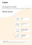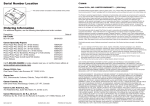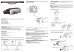
1
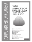
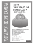
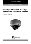
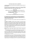
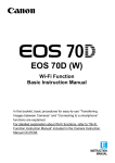
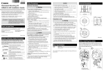
BIE-7067-000 Caution Please be sure to read the “Safety Precautions” section for correct use. After reading this Installation Guide, keep it in a readily accessible location for future reference. This camera is for indoor use only. * Some cameras are not available in certain countries or regions. camera yourself. Doing so may result in unforeseen accidents such as dropping the camera or electric shock. Template Setup CD-ROM Ceiling Plate Dedicated wrench Caution Dedicated accessory used to install the camera recessed into a wall or ceiling. Plenum Mounting Kit SR11-P-VB Pendant Mounting Kit PC640-VB Dedicated accessory is used to install the camera to the end of pipe that extends from high ceilings, such as in big-box stores. Dome Unit DU10-S-VB Canon AC Adapter PA-V18 Dedicated AC adapter for this camera. © CANON INC. 2015 Printed in Japan Symbols Indicating Safety Precautions This Installation Guide uses the following symbols to indicate important information the user should know in order to use the product safely. Explanations are provided for each symbol so that users will understand the level of importance for each. Be sure to observe these items. Warning Failure to follow the instructions accompanied by this symbol may result in death or serious injury. Caution Failure to follow the instructions accompanied by this symbol may result in injury. Caution Failure to follow the instructions accompanied by this symbol may result in property damage. Part Names 10 11 1 9 Warning 3 4 Serial_ _ _ _ _ _ _ _ _ _ _ _ _ _ _ _ _ 12 Please refer to the installation procedures or the Appendix – Specifications for specifications not listed below. Camera Lens Viewing Angle Min. Subject Illumination Pan Angle Range Tilt Angle Range 30x optical zoom (20x digital zoom) lens with auto focus For 16:9 aspect ratios Horizontal: 58.4° (W) – 2.1° (T) Vertical: 34.1° (W) – 1.2° (T) For 4:3 aspect ratios Horizontal: 58.4° (W) – 2.1° (T) Vertical: 45.0° (W) – 1.6° (T) Day Mode (color): 0.03 lux (F1.4, shutter speed 1/30 sec., when smart shade control is off, 50IRE) Night Mode (monochrome): 0.002 lux (F1.4, shutter speed 1/30 sec., when smart shade control is off, 50IRE) When using the Dome Unit (Smoked) (sold separately) Day Mode (color): 0.06 lux (F1.4, shutter speed 1/30 sec., when smart shade control is off, 50IRE) Night Mode (monochrome): 0.004 lux (F1.4, shutter speed 1/30 sec., when smart shade control is off, 50IRE) 360° continuous panning 180º (ceiling-mounted position: 0º – 180º) When the horizontal direction of the camera is 0° Memory card slot •Insert a memory card before installing the camera. •When using a memory card with the camera for the first time, it is recommended to format the card after inserting it into the camera (please refer to the “Operation Guide” > “Setting Page” > “Memory Card”). •Always unmount the memory card before removing it (please refer to the “Operation Guide” > “Setting Page” > “Memory Card”). Using the Dome Unit (sold separately) Remove the dome case from the camera, then remove the dome cover holder and dome flange, and replace with the smoked dome. Important •Take care when replacing so as not to scratch the dome cover. Dome flange 13 Notes on Power Supply 1. Dome case lock screw / 2. Dome case / 3. Interface cover lock screw / 4. Interface cover 5. Power connection terminal / 6. 100Base-TX LAN connector / 7. Audio input terminal (common LINE IN and MIC IN) / 8. Audio output terminal (LINE OUT) / 9. External device I/O terminals / 10. Reset switch / 11. Memory card slot / 12. Lens unit / 13. Mounting-release button Network Terminal LAN x 1 (RJ45, 100Base-TX (auto/full-duplex/half-duplex)) Audio Input Terminal 3.5 mm ( 0.14 in.) mini-jack connector (monaural) (Common for LINE IN & MIC IN) LINE IN (connect to an amplifier microphone) or MIC IN (connect to a microphone w/o amplifier) Switch LINE IN/MIC IN in the setting page. Audio Output Terminal 3.5 mm ( 0.14 in.) mini-jack connector (monaural) (LINE OUT) LINE OUT (connect to an amplifier speaker) External Device I/O Terminal Input x 2, Output x 2 Memory Card* SD Memory Card, SDHC Memory Card, SDXC Memory Card Compatible. Recorded Content: Log, Video (Event, Manual, ONVIF, Timer, Upload) Frame Rate: Max. 1 fps (JPEG) Max. 30 fps (H.264) * Use CLASS 10 cards. Cards under CLASS 10 may not have sufficient performance for tasks such as video recording. Dome cover Smoked dome cover Dome cover holder Others MAC_ _ _ _ _ _ _ _ _ _ _ _ _ _ _ _ _ _ Failure to do so may result in fire or electric shock. The contents of this guide are subject to change without any prior notice. Specifications Interface 2 Installation Precautions Failure to do so may result in fire or electric shock. Remove the dome case and place the memory card in the memory card slot. To remove the memory card, push it in all the way until the card slightly pops out and remove. *1 Ceiling mount holes *2 Junction box fixing holes *3 Ceiling mount holes position *4 Junction box fixing holes position Important •If thunder starts, stop installation or inspection etc. and do not touch the camera or continue connecting the cable. •Do not disassemble or modify the camera. •Do not damage the connecting cable. •Do not spray the camera with water, or otherwise make it wet. •Do not insert foreign objects such as water or metal into the camera. •Do not use flammable sprays near the camera. •Do not leave LAN cables, external power supply, or the power connector for the AC adapter (sold separately) connected when the camera is not in use for long periods. •Do not use flammable solvents such as alcohol, paint thinner or benzine when cleaning the camera. Failure to do so may result in fire or electric shock. 5 6 7 8 •Only use the dedicated AC Adapter (sold separately) for AC power. •Do not set any heavy objects on the power cable (or the LAN cable for a PoE power supply). •Do not pull, forcibly bend, scratch, or modify the power cable (or the LAN cable for a PoE power supply). •Do not cover or wrap the AC adapter (sold separately) with cloth or blankets. Unit: mm (in.) Using a Memory Card Warning Safety Precautions •Places in direct sunlight, near heat-generating objects, or locations subject to high temperatures •Places near fire sources or flammable solvents (alcohol, thinner, fuel, etc.) •Humid or dusty places •Places subject to oily smoke or steam •Places subject to sea air •Confined or enclosed places 83.5 (3-9/32) (*4) 85.7 (3-3/8) (*3,*4) Precautions for Use Contains reference information for operation or additional explanations. Do not install in the following places: 1. Align the marks on the camera and the dome case and turn it clockwise to attach it. 2. Tighten the dome case lock screw with the dedicated wrench. Unit: mm (in.) 10- 4.5 ( 0.18) (*2) •We recommend the installation of a lightning arrester (a surge protection device) as a measure against failures caused by lightning strikes. Refer to our website for details. Important This symbol indicates important or restricted items. Note Attaching the dome case 4- 4.5( 0.18) (*1) •Take care not to damage wiring or piping. Failure to do so may result in damage to peripheral items. •If you discover defective conditions such as smoke, strange sounds, heat or strange odors, immediately stop using the camera and contact your nearest dealer. Fire or electric shock may result from continued use of the product. Smoked dome cover. Loosen the dome case lock screw with the dedicated wrench and rotate it counter-clockwise to remove it. Camera mounting tab Important Dedicated accessory used to install the camera recessed into a ceiling. The part projecting out within the ceiling can be covered. Dome case removal method 8.2 (0.32) 46 (1-13/16) (*4) Recessed Mounting Kit SR11-S-VB 165 ( 6.50) 27 (1.06) 15(0.59) (*4) The following accessories can be purchased separately as necessary. Some accessories are not available in certain countries or regions. •Do not turn the camera rotator by hand. •Do not install on an unstable surface. Also, make sure the camera is installed ±5°or less horizontal. •After turning off the power, do not turn the power on again for at least five seconds. •Take measures to remove static electricity before performing any procedures. •If there is condensation, please wait to power on, until the condensation dissipates. Failure to do so may result in malfunction. 85.7(3-3/8) (*3) Accessories Dome case attachment/detachment method Dedicated wrench 26 (1.02) •Do not touch the edges of metal parts with bare hands. •Take care not to catch your fingers when installing. Failure to do so may result in injuries. Check Included Items Camera Installation Guide (This document) Warranty Card Notice Power connector •Do not install in unstable places, places subject to significant vibration or impact, or places subject to salt damage or corrosive gas. •Be sure to attach the safety wire when installing the camera. Failure to do so may result in the camera falling or other accidents. ) Caution Request a professional installer for all installation work. Never try to install the Cover at open position 15 3. (R moisture. Camera mounting tab slots 80 R WARNING To reduce a risk of fire or electric shock, do not expose this product to rain or •This installation should be made by a qualified service person and should conform to all local codes. •When installing, make sure the surface is capable of withstanding the total weight of the camera and accessories, and that it is sufficiently reinforced. •Be sure to use installation screws designed for the type of surface the camera is to be installed. •Periodically check the parts and screws for rust and loosening, in order to prevent injuries and equipment damage due to falling items. Set the IP address and other network information on the camera using the “Camera Management Tool” on the Setup CD-ROM. For details on how to operate the “Camera Management Tool”, please refer to the “Camera Management Tool User Manual”. 199 (7.83) Installation Guide Before installing the camera 30 (1.18) (RJ45 connector location) For installation or inspection of this camera, consult the dealer where you purchased the product. 9 ) 19 .83 7 ( Network Camera External Dimensions 85.7 (3-3/8) (*4) ENGLISH Operating Environment Temperature: AC, DC, PoE: -10°C – +50°C (+14°F – +122°F) Humidity: 5% – 85% (without condensation) Storage Environment Temperature: -30°C – +60°C (-22°F – +140°F) Humidity: 5% – 90% (without condensation) Installation Method Ceiling mount Canon will not guarantee proper operation if the cameras are installed on surfaces where the angle is more than ±5° from horizontal or on walls, because this will put a heavy load onto sliding mechanical parts and may affect durability. PoE: PoE power supply via LAN connector (IEEE802.3at Type1 compliant) Power Supply AC Adapter: PA-V18 (100 – 240 V AC) (sold separately) External power source: 24 V AC/12 V DC Power Consumption PoE: Max. approx. 9.5 W AC Adapter PA-V18: Max. approx. 9.6 W (100 V AC) Max. approx. 9.8 W (240 V AC) DC: Max. approx. 8.8 W AC: Max. approx. 9.2 W Weight Approx. 1990 g (4.39 lb.) Dedicated wrench 2 Installing the Camera 3 External Device I/O Terminals Removing the camera External device I/O terminals consist of two input and output systems each. Viewer can be used to check external device input status and control output to an external device (please refer to the “Operation Guide” > “External device output operation” and “Event display panel”). Remove the dome case, and while pushing the mounting-release button, rotate it counterclockwise to remove. 1 Direct-mounting on ceiling 1 -1 1 -2 External Device Input Terminals (IN1, IN2) External device input terminals consist of two sets (IN1, IN2) of two terminals, with the negative terminals connected to the camera interior GND. Connecting cables to the positive and negative terminals and opening or closing the circuit notifies the Viewer. c d a Important •When connecting sensors and switches, connect terminals that are electrically isolated from the respective power and GND. •Do not push the external device I/O terminal button with too much force. Doing so may cause the button to remain pushed-in. Dedicated wrench FRONT d. Safety wire External device output terminals consist of two sets (OUT1, OUT2) of two terminals. The sets have no polarity. Controls from the viewer can be used to open and close the circuit between the terminals. Using optical couplers, the output terminals are isolated from the camera’s internal circuit. Connecting the Camera 4 a. Template Using an external power supply 1 -3 Power Connection Power can be supplied to the camera in the three ways described below. Please be sure to read the user manual for the dedicated power supply before use. b Note e •Power supply should conform to all local codes. •The power supply should also comply with IEC/UL60950-1 (SELV/LPS) standards. •The camera does not have a power switch. Connecting and disconnecting the LAN cable (PoE power supply), AC adapter, or external power supply plug turns the power ON and OFF, respectively. •When the camera needs to be rebooted, perform the reboot operation from the camera setting page (please refer to the “Operation Guide” > “Setting Page” > “Maintenance”). Note Connect the cable after hooking around the tab, to prevent accidental removal. b. Ceiling plate If the cables cannot be stored above a ceiling Important If the cables cannot be stored above a ceiling made of concrete, etc., break the cutout section of the dome case using pliers to remove the section to guide the cables. 5 6 Dedicated wrench Cutout section ❷ Attaching to a junction box Attach the ceiling plate to the junction box after confirming the fixing holes locations with the external dimensions diagram. ❶ Ceiling recessed mounting •Check with your dealer for more information about PoE HUB and Midspan technology. Midspan (a LAN cable power supply device) is a device that, like a PoE HUB, supplies power to the camera via a LAN cable. •Some PoE HUBs allow the limitation of currents for each port, but applying limits may interfere with performance. If using this type of PoE HUB, do not limit the operating current. •Some PoE HUBs have limits for the total current consumption for the ports which can interfere with performance when multiple ports are in use. For more information, check the instruction guide for your PoE HUB. •When the camera is connected to both a PoE HUB and an external power supply (12 V DC or 24 V AC), power from the power supply first connected is given priority. But when both power supplies are connected, according to the combination, problems such as failure of the network connection may occur. When a problem has occurred, either shut off the PoE HUB power supply setting or use the AC adapter that is sold separately as the external power supply. Mount using Recessed Mounting Kit or Plenum Mounting Kit (each sold separately). For details please refer to the Installation Guide included with the kit. External Power Supply 12 V DC or 24 V AC input can be used. Connect the power connector included in the package, as shown below. Resetting the camera Screwdriver Tightening torque: 0.25 N·m (max.) Remove the dome case, and push in the power cable while pressing the reset switch. Release the switch once the LED starts to flash. When the LED stops flashing, the reset procedure is complete. Approx. 5 – 7 mm (0.20 – 0.28 in.) Mount using the Pendant Mounting Kit (sold separately). For details please refer to the Installation Guide included with the kit. 1 -1 12 V DC can be connected in a non-polar configuration. Important Strip Ceiling pendant mounting Power connector (included) 1 -2 ❷ •The power supply should be within the following voltage range. •24 V AC: Voltage fluctuation within ±10% of 24 V AC (50 Hz or 60 Hz ±0.5 Hz or less) Current supply capacity of at least 1.0 A per camera •12 V DC: Voltage fluctuation within ±10% of 12 V DC Current supply capacity of at least 1.5 A per camera •When using a 12 V DC battery power supply, be sure to connect resistors of at least 0.5 – 1.0 Ω/20 W in series to the power line. •For an external power supply, use a double-insulated device. Recommended Power Cables [Reference] Cable (AWG) ❸ LED ❶ 2.5 cm (1.0 in.) M3* Pass necessary cables for connecting the camera through the pipe. ❹ 24 22 20 18 16 Conductor size mm (in.) 0.52 ( 0.020) 0.65 ( 0.026) 0.82 ( 0.032) 1.03 ( 0.041) 1.30 ( 0.051) 12 V DC maximum cable lengthm (ft.) 5 (16.4) 9 (29.5) 14 (45.9) 23 (75.5) 32 (105.0) 24 V AC maximum cable lengthm (ft.) 11 (36.1) 18 (59.1) 29 (95.1) 46 (150.9) 64 (210.0) Use UL cable (UL-1015 or equivalent) for 12 V DC or 24 V AC wiring. The load connected to the output terminals should be within the following rating range. Rating between output terminals: Internal Connection Diagram Maximum voltage 50 V DC +3.3 V Continuous load current at or below 100 mA 1 kΩ 10 kΩ 10 kΩ On resistance: Max. 30 Ω Note Adaptive wiring for external device cables Solid conductor AWG: No. 28 – 22 Conductor size: 0.32 – 0.65 mm ( 0.013 – 0.026 in.) Cable strip should be approx. 8 – 9 mm (0.31 – 0.35 in.). *Included with Pendant Mounting Kit Input terminal IN1, IN2 External device Output terminal OUT1, OUT2 AC Adapter Each audio input/output terminal only has one input system and one output system. Connecting the camera to an audio input/output device such as a microphone or a speaker with an amplifier allows you to send/receive audio through the Viewer. Use the 3.5 mm ( 0.14 in.) monaural mini-jack connector to connect an audio input/output device. Audio Input Terminal Common LINE IN/MIC IN (monaural input) Although the camera only has a single audio input system, it supports two types of microphone input: LINE IN and MIC IN. Before using the audio input, please confirm the [Audio Input] on the Setting Page (please refer to the “Operation Guide” > “Audio Input”). LINE IN is selected by default. Input terminal: 3.5 mm ( 0.14 in.) mini jack (monaural) •Dynamic MIC IN Input impedance: 1.75 kΩ ±20% * Supported microphones: Output impedance: 400 – 600 Ω •Condenser MIC IN Input impedance (microphone bias resistance): 2.2 kΩ ±20% Microphone power supply: plug-in power (voltage: 1.8 V) * Supported microphones: Condenser microphones with plug-in power support •LINE IN Input level: Max. 1 Vp-p * Use a microphone with an amplifier. Audio Output Terminal LINE OUT (monaural output) Connect the camera to a speaker with an amplifier. Audio can be sent to the speaker from the Viewer. Output terminal: 3.5 mm ( 0.14 in.) mini jack (monaural) Output level: Max. 1 Vp-p * Use a speaker with an amplifier. Only for European Union and EEA (Norway, Iceland and Liechtenstein) These symbols indicate that this product is not to be disposed of with your household waste, according to the WEEE Directive (2012/19/EU), the Battery Directive (2006/66/EC) and/or national legislation implementing those Directives. If a chemical symbol is printed beneath the symbol shown above, in accordance with the Battery Directive, this indicates that a heavy metal (Hg = Mercury, Cd = Cadmium, Pb = Lead) is present in this battery or accumulator at a concentration above an applicable threshold specified in the Battery Directive. This product should be handed over to a designated collection point, e.g., on an authorized one-for-one basis when you buy a new similar product or to an authorized collection site for recycling waste electrical and electronic equipment (EEE) and batteries and accumulators. Improper handling of this type of waste could have a possible impact on the environment and human health due to potentially hazardous substances that are generally associated with EEE. Your cooperation in the correct disposal of this product will contribute to the effective usage of natural resources. For more information about the recycling of this product, please contact your local city office, waste authority, approved scheme or your household waste disposal service or visit www. canon-europe.com/weee, or www.canon-europe.com/battery. Please use the dedicated AC Adapter (sold separately). M4* × 4 External device 0.1 µF Audio Input/Output Terminals PoE (Power over Ethernet) The camera supports PoE functions. Power can be supplied to the camera by using a LAN cable connected to a PoE HUB that conforms to the IEEE802.3at Type1 standard. e. LAN cable External Device Output Terminals (OUT1, OUT2) Internal controller c. Interface cover CANON INC. 30-2, Shimomaruko 3-chome, Ohta-ku, Tokyo 146-8501, Japan CANON EUROPA N.V. Bovenkerkerweg 59, 1185 XB Amstelveen, The Netherlands