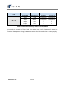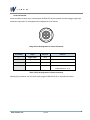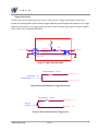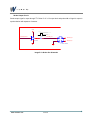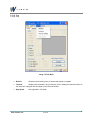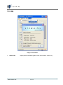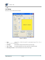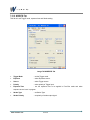
1
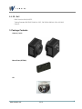
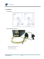
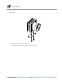
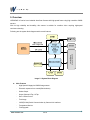
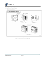
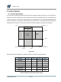
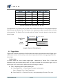
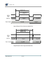
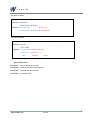
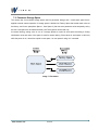
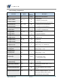
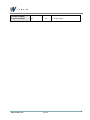
User Manual
Model : VC-3MC-M/C280
Revision History
Revison
Date
1.0
2010/10/01
Initial release
1.1
2010/12/13
Insert the missing commands (”scl”,”gcl”). page 31
1.2
2011/01/03
New Manual Design
www.vieworks.com
Descriptions
2 of 46
Contents
1. Precautions ---------------------------------------------------------------------------------------------------------------------------- 5
2. Compliance & Certifications-------------------------------------------------------------------------------------------------------- 5
2.1. FCC Declaration ------------------------------------------------------------ 5
3. Package Contents -------------------------------------------------------------------------------------------------------------------- 6
Mount Plate (OPTION) ------------------------------------------------------------ 6
CD
6
4. Installation ------------------------------------------------------------------------------------------------------------------------------ 7
PC Connection ----------------------------------------------------------------- 7
Camera (Camera Link Interface) ---------------------------------------------------- 7
Mount Plate 8
5. Overview -------------------------------------------------------------------------------------------------------------------------------- 9
5.1. Specifications ------------------------------------------------------------- 10
5.2. Spectral Response ---------------------------------------------------------- 11
5.3. Camera Interface ----------------------------------------------------------- 11
Camera Link Connector---------------------------------------------------------- 12
Power Input Connector ---------------------------------------------------------- 16
Control Connecter ------------------------------------------------------------- 17
Trigger Input Circuit ------------------------------------------------------------ 18
Strobe Output Circuit ----------------------------------------------------------- 19
5.4. Mechanical Specification ----------------------------------------------------- 20
Mechanical Dimension ---------------------------------------------------------- 20
6. Camera Features ------------------------------------------------------------------------------------------------------------------- 21
6.1. Area Of Interest (AOI)-------------------------------------------------------- 21
6.2. Trigger Mode -------------------------------------------------------------- 22
FreeRun Mode ---------------------------------------------------------------- 22
External Sync Mode ------------------------------------------------------------ 24
6.2.1.1. Overlap Trigger input ------------------------------------------------------------------------------------------------------- 25
6.3. Camera Link Output --------------------------------------------------------- 26
6.4. Gain and Offset ------------------------------------------------------------ 27
6.5. Temperature Monitor -------------------------------------------------------- 28
6.6. Status LED --------------------------------------------------------------- 28
6.7. Test Image --------------------------------------------------------------- 29
6.8. Strobe Out ---------------------------------------------------------------- 30
Strobe out Polarity ------------------------------------------------------------- 30
www.vieworks.com
3 of 46
6.9. Field Upgrade ------------------------------------------------------------- 31
6.10. Dark Image Correction ------------------------------------------------------ 31
7. Serial Communication ------------------------------------------------------------------------------------------------------------- 32
7.1. Setup command ----------------------------------------------------------- 32
Types of Error Code ------------------------------------------------------------ 33
7.2. Parameter Storage Space----------------------------------------------------- 34
Camera Setting Command List ---------------------------------------------------- 35
Camera Configuration Command List ----------------------------------------------- 37
7.3. Configurator GUI ----------------------------------------------------------- 38
Camera Scan ----------------------------------------------------------------- 38
Menu
39
7.3.1.1. File
39
7.3.1.2. Start-Up 40
7.3.1.3. Tool
41
7.3.1.4. Help
42
Tab
43
7.3.1.5. VIEW tab 43
7.3.1.6. MODE/EXP Tap ------------------------------------------------------------------------------------------------------------- 44
7.3.1.7. ANALOG Tab ----------------------------------------------------------------------------------------------------------------- 45
www.vieworks.com
4 of 46
1. Precautions
General
Do not drop or damage the device.
Do not disassemble, repair or alter the device.
Do not let children touch the device without supervision.
Do not use the device for any other purpose than specified.
Contact your nearest distributor in case of trouble or problem.
Installation & Maintenance
Do not install the device in a place subject to direct sun light, humidity, dust or soot.
Do not place magnets near the product.
Do not place the device next to heating equipments.
Be careful not to let liquid like water, drinks or chemicals leak inside the device.
Clean the device often to remove dust on it.
In clearing, do not splash water on the device but wipe it out with smooth cloth or towel.
Power Supply
It is recommended the use of 12V DC with ±10% of voltage, over 1A of output current with KC, CE
or other local certification. (※ Vieworks Co., Ltd. DO NOT provide power supplies with the
devices.)
If voltage over 16V is supplied, it will cause damages to the device.
2. Compliance & Certifications
2.1. FCC Declaration
This equipment has been tested and found to comply with the limits for a Class A digital device,
pursuant to part 15 of the FCC Rules. These limits are designed to provide reasonable protection
against harmful interference when the equipment is operated in a commercial environment. This
equipment generates, uses, and can radiate radio frequency energy and, if not installed and used
in
accordance
with
the
instruction
manual,
may
cause
harmful
interference
to
radio
communications. Operation of this equipment in a residential area is likely to cause harmful
interference in which case the user will be required to correct the interference at own expenses.
www.vieworks.com
5 of 46
2.2. CE : DoC
EMC Directive 2004/108/EC.
Testing Standard EN 55022:2006+A1:2007, EN 55024:1998+A1:2001+A2:2003
Class A
3. Package Contents
Camera (1 unit)
Mount Plate (OPTION)
CD
www.vieworks.com
6 of 46
4. Installation
PC Connection
Camera (Camera Link Interface)
-
Camera Link Cable Connection
-
Power Cable Connection
-
Control Cable Connection
www.vieworks.com
7 of 46
Mount Plate
-
The Mount Plate is provided as Option.
-
The camera can be fix without using this Mount Plate.
www.vieworks.com
8 of 46
5. Overview
VIEWORKS VC series is an industrial Area Scan Camera with high-speed frame using high resolution CMOS
sensors.
With its high reliability and durability, this camera is suitable for machine vision requiring high-speed
continuous shooting.
Following are the system block diagram and the main features.
CameraLink Full
Configuration
Image 5.1 System Block Diagram
Main Features
-
High Speed 3 Mega-pixel CMOS image sensor
-
Electronic exposure time control(Global shutter)
-
Strobe Output
-
Output Channel 8 Tap, 10 Tap
-
Gain / Offset Control
-
Test Image
-
LVDS(RS-644) Serial Communication by Camera Link Interface
-
Temperature Monitor
-
Field Upgrade
www.vieworks.com
9 of 46
5.1. Specifications
Model
Image Sensor
Active Size
Pixel Size
Quantum Efficiency
VC-3MC-M/C280
Cypress LUPA3000
1696 X 1710 ( 3 Mega pixels)
8.0 µm × 8.0 µm
37 %
at
680 nm with micro lens
Imaging Area
H × V : 13.56 × 13.68 mm (Diagonal : 18.55 mm)
Sensor Type
CMOS ( Mono / Color)
8 Taps (Full)
: 227 FPS
10 Taps (Full)
: 284 FPS
8 Taps (Full)
: 4.41 ms
10 Taps (Full)
: 3.51 ms
Frame Rate (at full Image)
Transfer Time (at full Image)
Dynamic Range
Exposure Control
60 dB
Electronic Global shutter
Pixel Clock
85 MHz
Data Output
8 bit
Camera-Link : CC1
Trigger Input
External Port : 3.3 – 5.0V Logic level input, optically isolated.
Gain Control
Offset Control
Range: 0~ 12 dB, 64-step Gain Control
Range: 0 ~ 63 LSB, 64-step Offset Control
Mechanical Spec.
68 mm x 68 mm x 54 mm, 420 g (With F-mount)
(W×H×L), weight
Lens Mount
Power Requirements
C Mount , F Mount
12 VDC ± 20% MAX 6.0 W @ 12 V DC
Case temperature : 0 °C ~ 50°C
Operation Temperature
Inner temperature : 0 °C ~ 70°C
Data Transfer/ Communication : Two, 26 pin, Female MDR connector
Connectors
Power : 6 pin, Hirose HR connector ,
Control : 4 pin, Hirose HR connector
Table 5.1 Specifications of VC Series
www.vieworks.com
10 of 46
5.2. Spectral Response
Image 5.2 Spectral Response for Mono and Color
5.3. Camera Interface
As shown in the following figure, 3 types of connectors and status indicator LED are located on the back of the
camera and have the functions as follows:
6 pin Power Input Connector : camera power input,
4 pin Control Connector : external trigger signal input and Strobe output
26 pin Camera-Link Connector #1 : video data transmission, camera control
26 pin Camera-Link Connector #2: video data transmission
Status LED : power and operation mode display
www.vieworks.com
11 of 46
Image 5.3 VC Series Connectors and LED
Camera Link Connector
CAMERA LINK 1
13
1
26
14
Image 5.4 Camera Link Connector
www.vieworks.com
12 of 46
Following list shows the pin configuration of connector.
PAIR List
Pin
Signal Name
Type
Description
1
Ground
Ground
Cable Shield
14
Ground
Ground
Cable Shield
2
-X0
LVDS - Out
Camera Link Transmitter
15
+X0
LVDS - Out
Camera Link Transmitter
3
-X1
LVDS - Out
Camera Link Transmitter
16
+X1
LVDS - Out
Camera Link Transmitter
4
-X2
LVDS - Out
Camera Link Transmitter
17
+X2
LVDS - Out
Camera Link Transmitter
5
-X3
LVDS - Out
Camera Link Transmitter
18
+X3
LVDS - Out
Camera Link Transmitter
6
-XCLK
LVDS - Out
Camera Link Transmitter
19
-XCLK
LVDS - Out
Camera Link Transmitter
7
- SerTC
LVDS - In
Serial Data Receiver
20
+ SerTC
LVDS - In
Serial Data Receiver
8
- SerTFG
LVDS - Out
Serial Data Transmitter
21
+ SerTFG
LVDS - Out
Serial Data Transmitter
9
- CC 1
LVDS - In
Software External Trigger
22
+ CC 1
LVDS - In
Software External Trigger
10
N/C
N/C
N/C
23
N/C
N/C
N/C
11
N/C
N/C
N/C
24
N/C
N/C
N/C
12
N/C
N/C
N/C
25
N/C
N/C
N/C
13
Ground
Ground
Cable Shield
26
Ground
Ground
Cable Shield
PAIR 0
PAIR 1
PAIR 2
PAIR 3
PAIR 4
PAIR 5
PAIR 6
PAIR 7
PAIR 8
PAIR 9
PAIR 10
PAIR 11
PAIR 12
Table 5.2 Pin Assignents for Camera Link Connector 1
www.vieworks.com
13 of 46
PAIR List
Pin
Signal Name
Type
Description
1
Ground
Ground
Cable Shield
14
Ground
Ground
Cable Shield
2
-Y0
LVDS - Out
Camera Link Transmitter
15
+Y0
LVDS - Out
Camera Link Transmitter
3
-Y1
LVDS - Out
Camera Link Transmitter
16
+Y1
LVDS - Out
Camera Link Transmitter
4
-Y2
LVDS - Out
Camera Link Transmitter
17
+Y2
LVDS - Out
Camera Link Transmitter
5
-Y3
LVDS - Out
Camera Link Transmitter
18
+Y3
LVDS - Out
Camera Link Clock Tx
6
-YCLK
LVDS - Out
Camera Link Channel Tx
19
+YCLK
LVDS - Out
Camera Link Channel Tx
PAIR 0
PAIR 1
PAIR 2
PAIR 3
PAIR 4
PAIR 5
7
Not Used
20
Not Used
Connected with 100 ohm
PAIR 6
8
-Z0
LVDS - Out
Camera Link Transmitter
21
+Z0
LVDS - Out
Camera Link Transmitter
9
-Z1
LVDS - Out
Camera Link Transmitter
22
+Z1
LVDS - Out
Camera Link Transmitter
10
-Z2
LVDS - Out
Camera Link Transmitter
23
+Z2
LVDS - Out
Camera Link Transmitter
11
-Z3
LVDS - Out
Camera Link Transmitter
24
+Z3
LVDS - Out
Camera Link Clock Tx
12
-ZCLK
LVDS - Out
Camera Link Channel Tx
25
+ZCLK
LVDS - Out
Camera Link Channel Tx
13
Ground
Ground
Cable Shield
26
Ground
Ground
Cable Shield
PAIR 7
PAIR 8
PAIR 9
PAIR 10
PAIR 11
PAIR 12
Table 5.3 Pin Assignments for Camera Link Connector 2
www.vieworks.com
14 of 46
Camera-Link
Camera-Link
Camera-Link
Camera-Link
Output Mode
Configuration
Connector 1
Connector 2
2 Tap’s
BASE
Not Supported
Not Supported
4 Tap’s
MEDIUM
Not Supported
Not Supported
8 Tap’s
FULL
O
O
10 Tap’s
FULL
O
O
Model
VC2 – 3M
Table 5.4 Connector Connection per Camera Link Output Mode
In connecting the connector to Frame Graber, it is required to be careful of sequence of Camera Link
Connector. If the sequence is changed, camera image output and serial communication do not work properly.
www.vieworks.com
15 of 46
Power Input Connector
Power input connector of camera is Hirose 6 pin connector(part # HR10A-7R-6PB). Pin arrangement and
configuration are as follows:
1
6
3
4
2
5
Image 5.5 Pin Arrangement of Power Input Connctor
Pin Number
Signal
Direction
Function
1, 2,3
+ 12V DC
Input
DC Power Input
4,5,6
DC Ground
Input
DC Ground
Table 5.5 Pin Configuration of Power Input Connector
Power plug can be configured using the Hirose 6 pin plug (part # HR10A-7P-6S) or compatible parts enclosed
in the camera box. For power supply, it is recommended to use the power adapter twith over 1A current output
at 12VDC ±10% voltage output.
Cautions for Power Input
Make sure to connect the power wiring of camera after checking the camera input power is turned
off. If not, it may result in damage of camera.
If the voltage over 16V is applied beyond the power voltage input of camera, circuit inside camera
can be damaged.
www.vieworks.com
16 of 46
Control Connecter
control connector is Hirose 4 pin connector(part # HR10A-7R-4S) and consists of external trigger signal input
and strobe output port. Pin arrangement and configuration are as follows:
4
1
3
2
Image 5.6 Pin Arrangement of Control Connector
Pin Number
Signal
Direction
Function
1
Trigger Input +
Input
2
Trigger Input -
Input
3
DC Ground
-
DC Ground
4
Strobe Out
Output
3.3V TTL Output
Output resistance : 47 Ω
Table 5.6 Pin Arrangement of Control Connector
Matching plug connector can use Hirose 4 pin plug(part # HR10A-7P-4P) or equivalent connector.
www.vieworks.com
17 of 46
Trigger Input Circuit
Following figure shows trigger signal input circuit of 4 pin connector. Trigger signal entered is delivered to
internal circuit through photo coupler. Minimum trigger width that can be recognized at camera is 1us. If trigger
signal entered is less than 1us, trigger signal is ignored in camera. External trigger signal can approve signals
to the circuits in the 2 methods shown below.
+5V
1 kΩ
330 Ω
STROBE_OUT +
4
1
3
2
TRIGGER_IN+
TRIGGER_IN
TRIGGER_IN-
PHOTO COUPLER
HR10A-7R-4SB
Image 5.7 Trigger Input Schematic
Output Resistance < 100 Ω
TRIGGER_IN + : Pin 1
Pulse Width > 1us
Amplitude Range : 3 V ~ 5 V
TRIGGER_IN - : PIN 2
Image 5.8 Recommended Pulse Trigger Driver Input
ON Resistance < 100 Ω
TRIGGER_IN - : Pin 2
Minimum
ON Time > 1us
GROUND
Image 5.9 Recommended Contact Trigger Input
www.vieworks.com
18 of 46
: PIN 3
Strobe Output Circuit
Strobe output signal is output through TTL Driver IC of 3.3 V output level and pulse width of signal is output in
synchronization with exposure of camera.
+3.3V
3.3 V
3.3 V
0 V
47 Ω
STROBE_SIGNAL
STROBE_OUT
TTL Driv er
4
1
TRIGGER_IN +
3
2
TRIGGER_IN -
HR10A-7R-4SB
Image 5.10 Strobe Out Schematic
www.vieworks.com
19 of 46
5.4. Mechanical Specification
Mechanical Dimension
Image 5.11 Mechanical Dimensions(in mm)
www.vieworks.com
20 of 46
6. Camera Features
6.1. Area Of Interest (AOI)
AOI is the area containing the data required by the user among total areas of image. The user can obtain the
image faster, with the quality same as when obtaining overall areas by designating the area as AOI when part
of area is required in all areas. AOI is determined as the overlapping area of 2 areas when designating Start
point and End point in horizontal and vertical direction as shown in Fig 6.1. Start point and End point mean the
starting and end of the area. The narrower Vertical and Horizontal AOI gets, the faster the frame speed.
(0, 0)
(HSIZE -1 , 1)
Horizontal
AOI
V Start
Vertical
AOI
Area Of
Interest
V End
(0, VSIZE - 1 )
(HSIZE -1, VSIZE - 1)
H Start
H End
Fig 6.1 AOI
Maximum frame speed depending on change of AOI size as shown in the following table.
AOI Size
2 Tap
4 Tap
8 Tap
10 Tap
640 X 480
-
-
1830 fps
2288 fps
1024 X 768
-
-
807 fps
1010 fps
1280 X 1024
-
-
486 fps
632 fps
1600 X 1200
-
-
346 fps
432 fps
1680 X 1680
-
-
229 fps
296 fps
1696 X 1710
-
-
227 fps
284 fps
Table 6.1 Maximum Frame Rate per AOI setting
www.vieworks.com
21 of 46
AOI Size
H Start
H End
V Start
V End
640 X 480
528
1167
615
1094
1024 X 768
336
1359
471
1238
1280 X 1024
208
1487
343
1366
1600 X 1200
48
1647
255
1454
1680 X 1680
8
1687
15
1694
1696 X 1710
0
1695
0
1709
Table 6.2 Optimum AOI Setting Value per AOI Size
The CMOS sensor for VC Series uses the Global Shutter method. Below Exposure Timing Diagram shows the
CMOS Exposure and Readout Time. The Readout of the photoelectron signals is proceed from the first line
and progressively. The Readout Time is normally called as Transfer Time and it shows the time that takes 1
frame of image.
Start of exposure
End of exposure
Trigger Signal
Input
Image
Read-out
Read-out Time
Image 6.1 Exposure Timing Diagram
6.2. Trigger Mode
Trigger mode of camera is divided into Free-Run mode where image is synchronized to Internal Trigger signal
created inside camera, and External Sync mode where image is synchronized to the trigger signal entered in
external port.
FreeRun Mode
In FreeRun mode, the cycle of internal trigger signal is determined by Transfer Time (1 Frame data
transmission time) and Exposure setting value, and image is obtained with such periodic signal. Cycle of
internal signal, that is, Frame Rate, is determined with the following 2 conditions.
Case 1 : Exposure Time < Frame Transfer time
Frame Rate(FPS) =
-
Case 2 : Exposure Time > Frame Transfer time
1/ Frame Tranfer Time (sec) : has fixed value
Frame Rate(FPS) = 1 / Exposure Time (sec) : change depending on Exposure Time value.
-
www.vieworks.com
22 of 46
Image 6.2 Exposure Time is Shorter than Readout Time
Image 6.3 Exposure Time is longer than Readout Time
www.vieworks.com
23 of 46
External Sync Mode
In External Sync Mode, camera keeps standby status until trigger signal is entered and performs image
transmission (Frame Transfer) after exposure process if trigger input occurs as shown in Image 6.4.
To
operate camera in External Sync mode, it is required to set Trigger Source regarding which input, CC1 input
port or External Trigger port, will be used for trigger signal, as well as Polarity and Exposure source of signal
entered.
Image 6.4 External Sync Mode
Following is the summary of basic setting items.
Trigger Source
: select either of CC1(Camera Control Port 1) and External Connector
as source of external trigger input signals.
Trigger Polarity
: set whether polarity of Trigger signal entered is Active High or
Active Low.
Exposure Source
: select to synchronize exposure time with pulse width of trigger
input signal or with exposure time programmed inside the camera.
www.vieworks.com
24 of 46
6.2.1.1. Overlap Trigger input
When trigger input occurs in the course of Frame Transfer and Image 6.5, it simultaneously performs exposure
of next image for new trigger input. In this case, image shooting is possible up to the speed of 1/Transfer
Time(sec), the Maximum Frame Rate conditions regardless of exposure time.
Image 6.5 Camera Operation at Input of Overlap Trigger
Following list shows the operation of camera on exceptional trigger input.
When the trigger signal with cycle faster than maximum FrameRate conditions, next Frame
Transfer is performed while one Frame Transfer is not completed, failing to obtain overall
image.
When new trigger input occurs in Exposure section while Exposure Source is set in Program,
the signal is ignored. It is the case that exposure setting value is set longer than trigger input
cycle, and since it is not synchronized for all trigger signal entered in camera, Frame Rate gets
slower than Trigger input cycle.
www.vieworks.com
25 of 46
6.3. Camera Link Output
VC-3M model supports 8 Tap and 10 Tap output modes according to user interface. Tap setting value means
the number of pixel data output for each cycle of Pixel Clock (85 MHz), and speed of Frame Data transmission
varies depending on tap setting. Frame Data is output in interleaved type and as shown in Image 6.6. This Tap
setting can be set using “scl” command.
Image 6.6 Camera Link Output configuration
www.vieworks.com
26 of 46
6.4. Gain and Offset
Gain and Offset can be changed through Voltage Reference adjustment applied commonly to all ADCs. Gain
adjustment scope can be set between 0 ~ 12 dB and setting value has values in 64 steps. Relation between
setting value and actual Gain(dB) are as shown below:
Gain(dB) = (setting value) x 0.19dB
Image 6.7 Register Setting vs Gain
Offset can be set between 0 ~ 64 (LSB) based on 8 bit Data output and setting value has a total of 64 steps
value.
www.vieworks.com
27 of 46
6.5. Temperature Monitor
Camera has sensor chip for monitoring internal temperature. “gct” command is used to check the temperature
of camera.
6.6. Status LED
Green LED on back of camera shows the operation status of camera. LED status and camera status
corresponding to this are as follows:
Continuous ON Status – camera operates in Free-Run Mode
ON for 0.5 sec. and OFF for 0.5 sec. repeats – camera operates in Trigger Mode.
ON for 1 sec. and OFF for 1 sec. repeats – Test Image is output.
ON for 0.25 sec. and OFF for 0.25 sec. repeats – operates in Trigger Mode and Test Image is
output
www.vieworks.com
28 of 46
6.7. Test Image
It can be set to output test image created inside instead of image data output from image sensor, in order to
check normal operation of camera. 3 types of test image are available; image with different values in horizontal
direction (Image 6.8), images with different values in diagonal direction (Image 6.9), and moving image with
different values in diagonal direction (Image 6.10). Test image can be applied to all operation modes of camera
and set using “sti” command.
Image 6.8 Test Image 1
Image 6.9 Test Image 2
www.vieworks.com
29 of 46
Image 6.10 Test Image 3 (Moving Pattern)
6.8. Strobe Out
Strobe output is the function to output the signal synchronized to exposure time of camera in operation, to
External Port. The wave form of the output signal is as below.
Image 6.11 Strobe Signal in Trigger Mode
Strobe out Polarity
Polarity can be set fur Strobe signal output. “ssp” command is used to set the polarity of strobe signal.
www.vieworks.com
30 of 46
6.9. Field Upgrade
This camera has the function to upgrade firmware and FGPA logic through RS-644 interface of CameraLink,
rather than disassembly of camera in the field. See Appendix A for how to change in details.
6.10. Dark Image Correction
Fixed Pattern Noise of CMOS sensor varies depending on operating temperature of camera due to change in
features according to temperature of ADC and sensor cell It may result in lower sensitivity at Dark Level.
Sensitivity change due to temperature change is less than 1 dB/10 degree. The variation due to temperature
change is not big and acquisition condition of corrected data is 25 degree based on case temperature. For
optimization of user to environmental conditions, it is recommended to correct after the temperature of camera
case gets stabilized while camera is installed.
Correction Sequence of Camera Dark Image
Fig. 6.12 Items of Dark Image Correction at Configurator
- How to Correct Image using Configurator
1. Prevent penetration of light into camera image sensor.
2. Click “Generate” button in “Dark Image Correction” item of “View” tab to generate correction data.
3. Click “Save Flash” button of “Dark Image Correction” item of “View” tab to save correction data in the flash
memory.
- How to Correct Image using Serial Command
1. Prevent penetration of light to camera image sensor.
2.Use terminal command “gop” to generate correction data in camera.
3. Use terminal command “sop” to save correction data in flash memory.
www.vieworks.com
31 of 46
7. Serial Communication
7.1. Setup command
All setup in camera is carried out RS-644 serial interface of camera link. With the following communication
setting, it can be controlled using terminal or direct control at user application.
BOUD Rate
: 19200 bps
Data Bit
: 8 bit
Parity Bit
: No Parity
Stop bit : 1 stop bit
Flow control
: None
All types of camera setting commands except Firmware Download, requiring massive data transmission are
delivered in ASCII command type. All camera setup commands start from user application and the camera
returns the response(“OK”, “Error” or information) for command The camera informs the completion of
command execution through response with write command, while the camera returns the error response or
information with read command.
Command format
<command> <parameter1> <parameter2> <cr>
0~2 parameters follow the command.
Response:
- If execution of write command is successfully completed
OK <cr> <lf> <prompt>
- If execution of read command is successfully completed
<parameter1> <cr> <lf> <prompt>
- If execution of command is not completed
Error : <Error Code> <cr> <lf> <prompt>
www.vieworks.com
32 of 46
ex) Write command
In response to a “set 100” command the camera will return (in hex value)
Command : set 100<cr>
( 73 65 74 20 31 30 30 0D )
Response : Set 100<cr><lf>
OK<cr><lf> >
( 73 65 74 20 31 30 30 0D 0A 4F 4B 0D 0A 3E)
Echo
ex) Read command
result
prompt
In response to a “get” command the camera will return (in hex value)
Command : get <cr>
67 65 74 0D
Response : 67 65 74 0D 0A 31 30 30 0D 0A 3E
get<cr><lf> 100<cr><lf>
echo
response
>
prompt
Types of Error Code
0x80000481 : values of parameter not valid
0x80000482 : number of parameter is not matched
0x80000484 : command that does not exist
0x80000486 : no execution right
www.vieworks.com
33 of 46
7.2. Parameter Storage Space
The camera has 3 non-volatile storage space used for parameter storage and 1 volatile work space that is
applied to actual camera operation. 3 storage space is divided into Factory Space that contain basic value at
the factory, and 2 user space(User Space 1, User Space 2) that can save parameter value temporarily set by
the user. User space can be read and written, but Factory space can be read only.
At camera booting, setting value in one of 3 storage spaces is copied to work space according to Config
Initialization value and value of the space is used for camera setting. Since values in work space is valid only
while the power is on, it should be copied to user space 1 or user space 2 using “sct” command.
.
Image 7.1 Parameter
www.vieworks.com
34 of 46
Camera Setting Command List
Value
Command
Syntax
Description
Returned
Help
h
Set Read-Out Mode
srm
Get Read-Out Mode
grm
String
Displays a list of all commands
0 : Nomal Mode
0|1
OK
1 : AOI(Area Of Interest) Mode
0|1
(AOI area is set using “sha” and “sva” commands)
Set Horizontal Area
sha n1 n2
Get Horizontal Area
gha
Set Vertical Area
sva n1 n2
Get Vertical Area
gva
Set Trigger Mode
stm
Get Trigger Mode
gtm
Set Trigger Source
sts
Get Trigger Source
OK
n1 n2
n2 : End point of horizontal direction
OK
n1 : Starting point of vertical direction
n1 n2
0|1
n1: Starting point of horizontal direction
n2 : End point of vertical direction
OK
0 : Free Run Mode
0|1
1 : Trigger/Overlap Mode
OK
1 : CC1 Port Input
gts
1|2
2 : External Input
Set Trigger Polarity
stp 0|1
OK
0 : Active Low
Get Trigger Polarity
gtp
0|1
1 : Active High
Set Exposure Time
set
OK
n : Exposure Time in us
Get Exposure Time
get
N
(Setting range : 10 ~ 7,000,000 us)
Set Analog Gain
sag n
OK
n :Analog Gain Parameter
get Analog Gain
gag
Set Analog Offset
sao n
get Analog Offset
gao
Set Test Image
sti
Get Test Image
gti
1|2
n
n
OK
n
0|1|2|3
OK
0|1|2|3
(Setting Range : 0 ~ 63)
n :Analog Gain Parameter
(Setting Range : 0 ~ 63)
0 : OFF
1,2 : Fixed Pattern Image
3 : Moving Pattern Image
Set Strobe Polarity
ssp 0|1
OK
0 : Active Low
Get Strobe Polarity
gsp
0|1
1 : Active High
Generate Offset-Calibration
god
OK
Generate offset Calibration Data to the
Data
Save Offset-Calibration Data
volatile Memory
sod
OK
Save offset Calibration Data to the Flash
Memory
Load Offset-Calibration Data
Lod
OK
Load offset Calibration Data from the Flash
Memory (the calibration data is loaded
Automatically at the Stat-up status)
www.vieworks.com
35 of 46
Set Camera-Link Mode
scl 2|3
OK
2 : 8 Tap’s Output
Get Camera-Link Mode
gcl
2|3
3 : 10 Tap’s Output
www.vieworks.com
36 of 46
Camera Configuration Command List
Value
Command
Syntax
Description
Returned
Save Config To
sct 1|2
OK
1 : Save to User 1 Setting
2 : Save to User 2 Setting
Load Config From
lcf
0|1|2
OK
0 : Load from Factory Setting
1 : Load from User 1 Setting
2 : Load from User 2 Setting
Set Config Initialization
sci 0|1|2
Get Config Initialization
gci
OK
0 : Load from Factory Setting when initializing
0|1|2
1 : Load from User 1 Setting when initializing
2 : Load from User 2 Setting when initializing
Get Model Name
gmn
String
Displays Model Name
Get MCU Version
gmv
String
Displays MCU Version
Get FPGA Version
gfv
String
Displays FPGA Version
Get Serial Number
gsn piece
String
Display Serial Number
Get Current Temperature
gct
String
Display Temperature Value
www.vieworks.com
37 of 46
7.3. Configurator GUI
Camera Scan
When you execute the program while the camera is turned on, Camera Scan window appears as shown in
Image 7.2. At this time, the program checks serial port of computer and DLL provided by CameraLink to scan
whether the camera is connected. If there is a camera connected, it displays model name on the screen. If the
camera is not properly displayed on the screen, check the connection of cable with power of camera and press
refresh button. When you double-click model name displayed on the screen, Configurator is executed and
displays current setting value of camera connected.
Image 7.2 Camera Cofigurator Loading Window
www.vieworks.com
38 of 46
Menu
7.3.1.1. File
Image 7.3 File Menu
-
Load Setting
: load setting value of camera, from setting value storage space(Factory,
User1, User2) inside the camera or file in the computer.
-
Save Setting
: save setting value of camera in setting value storage space(User1,
User2) inside the camera or file in the user computer.
-
Defect Pixel
:
Defect pixel download /upload not supported in VC-3M model.
-
System Upgrade
:
upgrade MCU program or FPGA logic.
-
Exit
:
exit program.
www.vieworks.com
39 of 46
7.3.1.2. StartStart-Up
The menu to select the space to load the setting value from, when the camera is turned on.
Image 7.4 Start-Up Menu
-
Factory Setting
: load the setting value from Factory space when camera is turned on.
-
User1 Setting
: load the setting value from User1 space when camera is turned on.
-
User2 Setting
: load the setting value from User2 space when camera is turned on.
www.vieworks.com
40 of 46
7.3.1.3. Tool
Image 7.5 Tool Menu
-
Refresh
: Read the current setting value of camera and display on program.
-
Terminal
: Display user command in GUI in terminal. Click to display the terminal window on
the lower part of program and click again to hide Terminal window.
-
High Speed
www.vieworks.com
: Not supported in VC Model.
41 of 46
7.3.1.4. Help
Image 7.6 About Menu
-
Camera Info
www.vieworks.com
: display camera information (product name, serial number, version, etc.).
42 of 46
Tab
7.3.1.5. VIEW tab
This tab is to control overall functions of camera.
Image 7.7 VIEW Tab
.
-
Mode
: Normal 모드는 카메라의 Full 해상도의 영상을 출력하며 AOI 모드는 미리 설
정된 국소 영역의 영상을 출력한다.
-
Test Image
: select whether to apply test image and the type of test image.
-
Tap’s Output
: set camera link(Camera-Link) output mode.(Only VC-4M110C Model)
-
Dark Image Correction : correct Fixed Pattern Noise at camera dark image
www.vieworks.com
43 of 46
7.3.1.6. MODE/EXP Tap
This tab is to set Trigger mode, exposure time and Strobe setting.
Image 7.8 MODE/EXP Tab
-
Trigger Mode
: set the Trigger mode.
-
Exposure
: select Exposure source.
-
Source
: select Trigger source.
-
Polarity
: select polarity of Trigger input.
-
Exposure Time
: set the exposure time to be applied in Free-Run mode and when
exposure source is set in program.
-
Strobe Type
: set Strobe Type.
-
Strobe Polarity
: set polarity of strobe output signal.
www.vieworks.com
44 of 46
7.3.1.7. ANALOG Tab
This tab is to set gain and Offset setting of image.
Image 7.9 ANALOG Tab
-
Analog Gain
: set gain value.
-
Analog Offset
: set offset value.
www.vieworks.com
45 of 46
Vieworks Co., Ltd.
#604 SuntechcityⅡ, 307-2 Sangdaewon-dong,
Jungwon-gu, Seongnam-city, Gyeonggi-do, 462-806
Tel: +82-70-7011-6161
www.vieworks.com
South Korea
Fax: +82-31-737-4954
[email protected]