1
WPI Robotics
Library User’s Guide
Worcester Polytechnic Institute Robotics Resource Center
Brad Miller, Ken Streeter, Beth Finn, Jerry Morrison, Dan Jones, Ryan
O’Meara, Derek White, Stephanie Hoag
January 7, 2010
Jan
Brad Miller
November 2009
Rev 1.0
Stephanie Hoag December 2009
Rev 2.0
Contents
Stuff to do ..................................................................................................................................... 6
Using the WPI Robotics Library............................................................................................. 7
What is the WPI Robotics Library?..................................................................................................... 7
Using the WPI Robotics Library User’s Guide ............................................................................... 8
Choosing Between C++ and Java ......................................................................................... 11
Language Differences ........................................................................................................................... 11
WPILib Differences .............................................................................................................................. 12
Our version of Java ............................................................................................................................... 12
Sensors........................................................................................................................................ 14
Types of supported sensors ................................................................................................................. 14
Digital I/O Subsystem ............................................................................................................. 15
Digital Inputs .......................................................................................................................................... 15
Digital Outputs ....................................................................................................................................... 16
Accelerometer (2009 part) ..................................................................................................... 17
Accelerometer (2010 part) ..................................................................................................... 18
Gyro ............................................................................................................................................ 19
Using the Gyro class ............................................................................................................................. 19
Setting the gyro sensitivity.................................................................................................................. 19
HiTechnicCompass .................................................................................................................. 22
Ultrasonic rangefinder............................................................................................................ 23
Counter Subsystem.................................................................................................................. 25
Counter Objects ...................................................................................................................................... 25
Encoders ................................................................................................................................................... 25
Gear Tooth Sensor ................................................................................................................................. 26
Encoders ................................................................................................................................................... 27
Quadrature Encoders ............................................................................................................................ 28
Analog Inputs ........................................................................................................................... 30
Analog Triggers ..................................................................................................................................... 32
Controlling Actuators ............................................................................................................. 33
Motors ....................................................................................................................................................... 33
PWM ......................................................................................................................................................... 34
Victor......................................................................................................................................................... 34
Jaguar ........................................................................................................................................................ 34
Servo .......................................................................................................................................................... 35
RobotDrive .............................................................................................................................................. 35
Relays.......................................................................................................................................... 38
Using the serial port ................................................................................................................ 40
Using I2C ................................................................................................................................... 41
Pneumatics ................................................................................................................................ 42
Compressor .............................................................................................................................................. 42
C++ Object Life Span........................................................................................................................... 43
Solenoid .................................................................................................................................................... 43
Getting Feedback from the Driver Station ........................................................................ 45
Getting Data from the Digital and Analog Ports .......................................................................... 45
Other Driver Station Features ............................................................................................................ 46
Joysticks ................................................................................................................................................... 46
Enhanced I/O through the Cypress Module ....................................................................................... 49
Configuring the Enhanced I/O ........................................................................................................... 50
Enhanced I/O data ................................................................................................................................. 50
Sending data to the dashboard ........................................................................................................... 51
Adding dashboard data to your robot program ............................................................................. 51
2010 Camera and Image Processing ................................................................................... 53
Using the camera ................................................................................................................................... 53
Working with images............................................................................................................................ 53
Use of image memory .......................................................................................................................... 54
Image types .............................................................................................................................................. 54
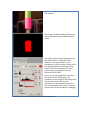
Common ColorImage operations ...................................................................................................... 55
Threshold detection ............................................................................................................................... 55
Plane extraction and replacement ..................................................................................................... 57
Ellipse detection ..................................................................................................................................... 57
Miscellaneous ............................................................................................................................ 59
PID Programming .................................................................................................................................. 59
Multitasking (C++)................................................................................................................................ 60
Creating tasks .......................................................................................................................................... 60
Synchronizing tasks .............................................................................................................................. 61
Timers ....................................................................................................................................................... 62
Notification .............................................................................................................................................. 62
System Architecture ................................................................................................................ 64
Contributing to the WPI Robotics Library ....................................................................... 65
Appendix A: 2009 Camera and Vision ............................................................................... 66
Camera ...................................................................................................................................................... 66
Camera task management.................................................................................................................... 66
Camera sensor property configuration ............................................................................................ 66
Sensor property configuration using a text file ............................................................................. 67
Simple Camera initialization .............................................................................................................. 67
Configurable Camera initialization .................................................................................................. 68
Image Acquisition ................................................................................................................................ 68
Camera Metrics ...................................................................................................................................... 69
Images to PC ........................................................................................................................................... 69
Vision / Image Processing ................................................................................................................... 69
Color Tracking........................................................................................................................................ 70
Example 1: Using Defaults ................................................................................................................. 70
Example 2: Using Specified Ranges ................................................................................................ 71
Example 3: Using Return Values ...................................................................................................... 71
Example 4: Two Color Tracking ....................................................................................................... 72
Stuff to do
TODO: redo Joe’s pictures and get some better explanations.
TODO: make the serial and I2C sections about communications.
TODO: Find the comments in the Java and C++ forums about the documentation
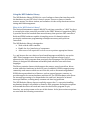
Using the WPI Robotics Library
The WPI Robotics library (WPILib) is a set of software classes that interfaces with
the hardware in your FRC robot’s control system. There are classes to handle
sensors, motors, the driver station, and a number of other utility functions such as
timing and field management.
What is the WPI Robotics Library?
The National Instruments compact RIO-9074 real-time controller or “cRIO” for short
is currently the robot controller provided by the FIRST Robotics Competition (FRC).
It provides about five hundred times more memory than previous FRC controllers.
Dedicated FPGA hardware capable of sampling across 16 channels replaces
previously cumbersome programming techniques necessary with previous
controllers.
The WPI Robotics library is designed to:
Work with the cRIO controller.
Handle low level interfacing of components.
Allow users of all experience levels access to experience appropriate features.
C++ and Java are the two choices of text-based languages available for use on the
cRIO. These languages were chosen because they represent a better level of
abstraction for robot programs than previously used languages. The WPI Robotics
Library is designed for maximum extensibility and software reuse with these
languages.
The library contains classes which support the sensors, speed controllers, driver
station, and other hardware in the kit of parts. In addition, WPILib supports many
commonly used sensors which are not in the kit, such as ultrasonic rangefinders.
WPILib has a generalized set of features, such as general-purpose counters, to
provide support for custom hardware and devices. The FPGA hardware also allows
for interrupt processing to be dispatched at the task level, instead of as kernel
interrupt handlers, reducing many common real-time bug problems.
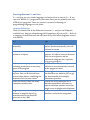
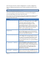
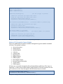
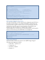
The WPI Robotics library does not explicitly support the C++ exception handling
mechanism, though it is available to teams for their programs. Uncaught exceptions
will unwind the entire call stack and cause the whole robot program to quit,
therefore, we caution teams on the use of this feature. In the Java version exceptions
are used with the following conventions:
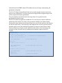
Exception type
Checked exceptions
How they are used
Used in cases where runtime errors should be caught by
the user program. Library methods that throw checked
exceptions must be wrapped in a try-catch block.
Unchecked exceptions Used for cases like bad port numbers in initialization code
that should be caught during the most basic testing of the
program. These don’t require try-catch blocks by the user
program.
Objects are dynamically allocated to represent each type of sensor. An internal
reservation system for hardware is used to prevent reuse of the same ports for
different purposes (though there is a way around it if necessary).
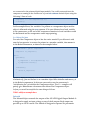
In the C++ version the source code for the library will be published on a server for
teams to review and make comments. In the Java version the source code is included
with each release. There will also be a repository for teams to develop and share
community projects for any language including LabVIEW.
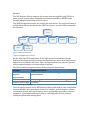
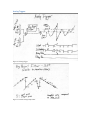
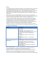
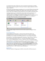
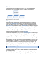
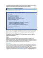
Using the WPI Robotics Library User’s Guide
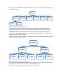
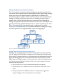
This document is designed to help you use WPILib to program your robot. The
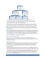
general architecture of the WPI Robotics Library documentation is shown below.
WPI Robotics
Library
Programming
environment
C++
Hardware and
control
Java
Sensors
Feedback
Actuators
Control
Figure 1: WPILib Structure Flowchart
As shown by the flowchart above, the WPI Robotics Library supports environments
for both the C++ and Java programming languages. These environments and
programming languages are discussed and explained in the “Getting Started With
Java For FRC” and “Getting Started With C++ For FRC” documents. Both of these
documents, along with other supportive materials, can be found online at
http://first.wpi.edu in the FIRST Robotics Competition section.
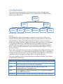
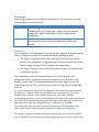
The WPI Robotics Library User’s Guide addresses the Hardware and Control branch
of the WPILib structure. A more detailed view of what this involves is shown in the
series of charts below.
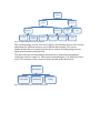
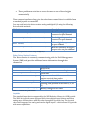
The first primary section of the user’s guide is the sensors section. This section
discusses how to use the sensors provided in the FRC kit of parts, as well as a few
other sensors commonly used on FRC robots. The structure of this section is shown
in the chart below:
Sensors
Vision system
Camera
Accelerometer
Gyro
Compass
Rangefinder
Encoders
Image
processing
Figure 2: WPILib Sensors section organization
As shown in the sensors flowchart above, each sensor subsection includes basic
information about the sensor, any necessary calibration or settings, as well as an
example of how to implement the sensors in your robot program. The camera
section also includes information about image processing and color tracking, both
commonly used with FRC robots.
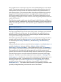
The next primary section discusses actuators, such as motors and pneumatics, and is
represented in the chart below:
Actuators
Motors
Victors
Jaguars
Pneumatics
Servos
Solenoids
Relays
Figure 3: WPILib Actuators section organization
The actuator section describes different types of motor control and solenoid control,
including the use of speed controllers, relays and solenoids.
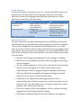
The next section, feedback, is outlined in the chart below:
Feedback
To robot
From robot
Regular I/O
Joysticks
Enhanced I/O
Digital and
analog inputs
PWM inputs
Encoders
Dashboard
output
Accelerometer
Video
Touchpad
Figure 4: WPILib feedback section organization
The second primary section of the user’s guide is the feedback section. This section
talks about two different aspects: user feedback and response. This covers
feedback/data that you can get from the driver station, including using buttons,
lights, potentiometers and joysticks.
The miscellaneous section primarily discusses more advanced programming
techniques used for control, i.e. PID control, multitasking (in C++), and other select
topics. The structure of the control section is shown in the chart below:
Miscellaneous
Control (PID)
Multitasking
Figure 5: WPILib miscellaneous section organization
Timing
Choosing Between C++ and Java
C++ and Java are very similar languages; in fact Java has its roots in C++. If you
can write WPILib C++ programs for your robot, then you can probably also write
WPILib Java programs. There are, however, reasons for choosing on
programming language over the other.
Language Differences
There is a detailed list of the differences between C++ and Java on Wikipedia
available here: http://en.wikipedia.org/wiki/Comparison_of_Java_and_C++. Below is
a summary of the differences that will most likely effect robot programs created
with WPILib.
C++
Java
Memory allocated and freed
manually.
Objects must be allocated manually,
but are freed automatically when no
references remain.
References to objects instead of
pointers. All objects must be allocated
with the new operator and are
referenced using the dot (.) operator.
(e.g. gyro.getAngle() )
Header files are not necessary and
references are automatically resolved
as the program is built.
Only single inheritance is supported,
but interfaces are added to Java to get
the most benefits that multiple
inheritance provides.
Checks for array subscripts out of
bounds, uninitialized references to
objects and other runtime errors that
might occur in program development.
Compiles to byte code for a virtual
machine, and must be interpreted.
Pointers, references, and local
instances of objects.
Header files and preprocessor used for
including declarations in necessary
parts of the program.
Implements multiple inheritance
where a class can be derived from
several other classes, combining the
behavior of all the base classes.
Does not natively check for many
common runtime errors.
Highest performance on the platform,
because it compiles directly to
machine code for the PowerPC
processor in the cRIO.
Table 1: Java/C++ Difference Summary
WPILib Differences
In order to streamline transitions between C++ and Java, all WPILib classes and
methods have the same names in both languages. There are some minor
differences between the language conventions and utility functions. These
differences are detailed in the table below:
Item
Method naming
convention
Utility functions
C++
Upper case first letter and
camel case after.
e.g. GetDistance()
Call function.
e.g. Wait(1.0) will wait for
one second.
Java
Lower case first letter and
camel case thereafter.
e.g. getDistance()
Library functions are
implemented as methods.
e.g. Timer.delay(1.0) will
wait for one second.
Table 2: Java/C++ Differences within WPILib
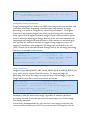
Our version of Java
The Java virtual machine and implementation used with WPILib is the Squawk
platform based on the Java ME (micro edition) platform. Java ME is a simplified
version of Java designed for the limitations of embedded devices. As a result,
there are no user interface classes or other classes that are not meaningful in this
environment. The most common Java platform is the Java Standard Edition (SE).
Some of the SE features that are not included in our version of Java are described
in the list below.
Dynamic class loading is not supported for class loading or unloading.
Reflection, a way of manipulating classes while the program is running, is
also not supported.
The Java compiler generates a series of byte codes for the virtual machine.
When you create a program for the cRIO with Java ME, a step is
automatically run after the program compiles (called pre-verification).
This pre-verification pass simplifies the program loading process and
reduces the size of the Java virtual machine (JVM).
Finalization is not implemented, meaning the system will not
automatically call the finalize() method of an unreferenced object. If you
need to be sure code runs when a class is no longer referenced, you must
explicitly call a method that cleans up.
Java Native Interface (JNI) is not supported. This is a method of calling C
programs from Java using a standard technique.
Serialization and Remote Method Invocation (RMI) are not supported.
The user interface APIs (Swing and AWT) are not implemented.
Threads are supported, but thread groups are not.
Java ME is based on an earlier version of Java SE (1.3), so it doesn’t include
newer Java features, such as generics, annotations and autoboxing.
Sensors
The WPI Robotics Library supports the sensors that are supplied in the FRC kit of
parts, as well as many other commonly used sensors available to FIRST teams
through industrial and hobby robotics outlets.
The WPILib supported sensors are listed in the chart below. The supported sensors
include those that are provided in the FIRST kit of parts, as well as other commonly
used sensors.
Sensors
Vision system
Camera
Accelerometer
Gyro
Compass
Rangefinder
Encoders
Image
processing
Figure 6: WPILib sensor section
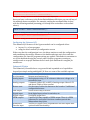
Types of supported sensors
On the cRIO, the FPGA implements all the high-speed measurements through
dedicated hardware ensuring accurate measurements no matter how many sensors
and motors are added to the robot. This is an improvement over previous systems,
which required complex real-time software routines.
The library natively supports sensors of the categories shown below.
Category
Wheel/motor
position
measurement
Robot orientation
Generic pulse output
Supported Sensors
Gear-tooth sensors, encoders, analog encoders, and
potentiometers
Compass, gyro, accelerometer, ultrasonic rangefinder
Counters
Table 3: List of Supported Sensors
There are many features in the WPI Robotics Library that make it easy to implement
sensors that don’t have prewritten classes. For example, general-purpose counters
can measure period and count from any device generating output pulses. Another
example is a generalized interrupt facility to catch high-speed events without
polling and potentially missing them.
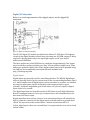
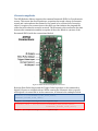
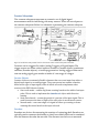
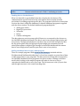
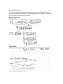
Digital I/O Subsystem
Below is a visual representation of the digital sidecar, and the digital I/O
subsystem.
Figure 7: Digital I/O Subsystem Diagram
The NI 9401 digital I/O module provided in the kit has 32 GPIO lines. Through the
circuits in the digital breakout board, these lines map into 10 PWM outputs, 8 Relay
outputs for driving Spike relays, the signal light output, an I2C port, and 14
bidirectional GPIO lines.
The basic update rate of the PWM lines is a multiple of approximately 5 ms. Jaguar
speed controllers update at slightly over 5ms, Victors update at slightly over 10ms,
and servos update at slightly over 20ms. Higher update rates may be possible using
the CAN bus and a community developed software available from
http://firstforge.wpi.edu.
Digital Inputs
Digital inputs are generally used for controlling switches. The WPILib DigitalInput
object is typically used to get the current state of the corresponding hardware line: 0
or 1. More complex uses of digital inputs, such as encoders or counters, are handled
by using the appropriate classes. Using these other supported device types
(encoder, ultrasonic rangefinder, gear tooth sensor, etc.) doesn’t require a digital
input object to be created.
The digital input lines are shared from the 14 GPIO lines on each Digital Breakout
Board. Creating an instance of a DigitalInput object will automatically set the
direction of the line to input.
Digital input lines have pull-up resistors so an unconnected input will naturally be
high. If a switch is connected to the digital input it should connect to ground when
closed. The open state of the switch will be 1 and the closed state will be 0.
In Java, digital input values are true and false. So an open switch is true and a closed
switch is false.
Digital Outputs
Digital outputs are typically used to run indicators or to interface with other
electronics. The digital outputs share the 14 GPIO lines on each Digital Breakout
Board. Creating an instance of a DigitalOutput object will automatically set the
direction of the GPIO line to output. In C++, digital output values are 0 and 1
representing high (5V) and low (0V) signals. In Java, the digital output values are
true (5V) and false (0V).
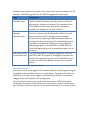
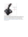
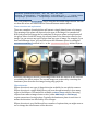
Accelerometer (2009 part)
The two-axis accelerometer provided in the kit of parts (shown in the picture
below) is a two-axis accelerometer. This device can provide acceleration data in the
X and Y axes relative to the circuit board. In the WPI Robotics Library you treat it as
two separate devices, one for the X axis and the other for the Y axis. This provides
better performance if your application only needs to use one axis. The
accelerometer can be used as a tilt sensor – actually measuring the acceleration of
gravity. In this case, turning the device on the side would indicate 1000 milliGs or
one G.
Figure 8: FRC supplied 2 -axis accelerometer board connected to a robot
Accelerometer (2010 part)
The 2010 accelerometer is not currently available as a built-in class, but we expect it
will be available shortly after the kickoff. It will operate using the I2C interface to
the robot controller. Teams are free to interface it themselves using the I2C class
already built into WPILib.
Gyro
Gyros typically in the FIRST kit of parts are provided by Analog Devices, and are
actually angular rate sensors. The output voltage is proportional to the rate of
rotation of the axis normal to the top package surface of the gyro chip. The value is
expressed in mV/°/second (degrees/second or rotation expressed as a voltage). By
integrating (summing) the rate output over time, the system can derive the relative
heading of the robot.
Another important specification for the gyro is its full-scale range. Gyros with high
full-scale ranges can measure fast rotation without “pinning” the output. The scale is
much larger so faster rotation rates can be read, but there is less resolution due to a
much larger range of values spread over the same number of bits of digital to analog
input. In selecting a gyro, you would ideally pick the one that had a full-scale range
that matched the fastest rate of rotation your robot would experience. This would
yield the highest accuracy possible, provided the robot never exceeded that range.
Using the Gyro class
The Gyro object should be created in the constructor of the RobotBase derived
object. When the Gyro object is used, it will go through a calibration period to
measure the offset of the rate output while the robot is at rest. This requires that the
robot be stationary and the gyro is unusable until the calibration is complete.
Once initialized, the GetAngle()(or getAngle() in Java) method of the Gyro
object will return the number of degrees of rotation (heading) as a positive or
negative number relative to the robot’s position during the calibration period. The
zero heading can be reset at any time by calling the Reset() (reset() in Java)
method on the Gyro object.
Setting the gyro sensitivity
The Gyro class defaults to the settings required for the 80°/sec gyro that was
delivered by FIRST in the 2008 kit of parts.
To change gyro types call the SetSensitivity(float sensitivity) method
(or setSensitivity(double sensitivity) in Java) and pass it the sensitivity in
volts/°/sec. Take note that the units are typically specified in mV (volts / 1000) in
the spec sheets. For example, a sensitivity of 12.5 mV/°/sec would require a
SetSensitivity() (setSensitivity() in Java) parameter value of 0.0125.
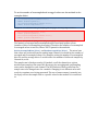
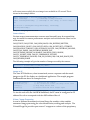
The following example programs cause the robot to drive in a straight line using the
gyro sensor in combination with the RobotDrive class. The RobotDrive.Drive
method takes the speed and the turn rate as arguments; where both vary from -1.0
to 1.0. The gyro returns a value indicating the number of degrees positive or
negative the robot deviated from its initial heading. As long as the robot continues to
go straight, the heading will be zero. This example uses the gyro to keep the robot
on course by modifying the turn parameter of the Drive method.
The angle is multiplied by Kp to scale it for the speed of the robot drive. This factor is
called the proportional constant or loop gain. Increasing Kp will cause the robot to
correct more quickly (but too high and it will oscillate). Decreasing the value will cause
the robot correct more slowly (maybe never getting back to the desired heading). This is
known as proportional control, and is discussed further in the PID control section of the
advanced programming section.
class GyroSample : public SimpleRobot
{
RobotDrive myRobot; // robot drive system
Gyro gyro;
static const float Kp = 0.03;
public:
GyroSample():
myRobot(1, 2),
// initialize the sensors in initialization list
gyro(1)
{
GetWatchdog().SetExpiration(0.1);
}
void Autonomous()
{
gyro.Reset();
while (IsAutonomous())
{
GetWatchdog().Feed();
float angle = gyro.GetAngle();
// get heading
myRobot.Drive(-1.0, -angle * Kp); // turn to correct heading
Wait(0.004);
}
myRobot.Drive(0.0, 0.0);
// stop robot
}
};
Example 1:
A C++ program example to drive in a straight line using a gyro.
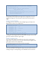
package edu.wpi.first.wpilibj.templates;
import
import
import
import
edu.wpi.first.wpilibj.Gyro;
edu.wpi.first.wpilibj.RobotDrive;
edu.wpi.first.wpilibj.SimpleRobot;
edu.wpi.first.wpilibj.Timer;
public class GyroSample extends SimpleRobot {
private RobotDrive myRobot; // robot drive system
private Gyro gyro;
double Kp = 0.03;
public GyroSample()
{
getWatchdog().setExpiration(0.1);
}
protected void Autonomous() {
gyro.reset();
while (isAutonomous()) {
getWatchdog().feed();
double angle = gyro.getAngle();
// get heading
myRobot.drive(-1.0, -angle*Kp); // drive to heading
Timer.delay(0.004);
}
myRobot.drive(0.0, 0.0);
// stop robot
}
};
Example 2:
Java program example to drive in a straight line using a gyro.
HiTechnicCompass
The compass uses the earth’s magnetic field to determine the heading. This field is
relatively weak causing the compass to be susceptible to interference from other
magnetic fields such as those generated by the motors and electronics on your
robot. If you decide to use a compass, be sure to mount it far away from interfering
electronics and verify tits accuracy. Additionally, the compass connects to the I2C
port on the digital I/O module. It is important to note that there is only one I2C port
on each of these modules.
HiTechnicCompass compass(4);
compVal = compass.GetAngle();
Example 3:
A C++ program to create a compass on the I2C port of the digital module plugged into slot 4.
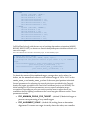
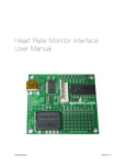
Ultrasonic rangefinder
The WPI Robotics library supports the common Devantech SRF04 or Vex ultrasonic
sensor. This sensor has two transducers, a speaker that sends a burst of ultrasonic
sound, and a microphone that listens for the sound to be reflected off of a nearby
object. It requires two connections to the cRIO, one that initiates the ping and the
other that tells when the sound is received. The Ultrasonic object measures the time
between the transmission and the reception of the echo. Below is a picture of the
Devantech SRF04, with the connections labeled.
Figure 9: SRF04 Ultrasonic Rangefinder connections
Both the Echo Pulse Output and the Trigger Pulse Input have to be connected to
digital I/O ports on a digital sidecar. When creating the Ultrasonic object, specify
which ports it is connected to in the constructor, as shown in the examples below.
Ultrasonic ultra(ULTRASONIC_ECHO_PULSE_OUTPUT,
ULTRASONIC_TRIGGER_PULSE_INPUT);
Example 4:
C++ example of creating an ultrasonic rangefinder object
Ultrasonic ultra = new Ultrasonic(ULTRASONIC_ECHO_PULSE_OUTPUT,
ULTRASONIC_TRIGGER_PULSE_INPUT);
Example 5:
Java example of creating an ultrasonic rangefinder object.
In this case, ULTRASONIC_ECHO_PULSE_OUTPUT and
ULTRASONIC_TRIGGER_PULSE_INPUT are two constants that are defined to be
the digital I/O port numbers.
Do not use the ultrasonic class for ultrasonic rangefinders that do not have these
connections. Instead, use the appropriate class for the sensor, such as an
AnalogChannel object for an ultrasonic sensor that returns the range as a voltage.
The following two examples read the range on an ultrasonic sensor connected to the
output port ULTRASONIC_PING and the input port ULTRASONIC_ECHO.
Ultrasonic ultra(ULTRASONIC_PING, ULTRASONIC_ECHO);
ultra.SetAutomaticMode(true);
int range = ultra.GetRangeInches();
Example 6:
C++ example of creating an ultrasonic sensor object in automatic mode and getting the range.
Ultrasonic ultra = new Ultrasonic(ULTRASONIC_PING, ULTRASONIC_ECHO);
ultra.setAutomaticMode(true);
int range = ultra.getRangeInches();
Example 7:
Java example of creating an ultrasonic sensor object in automatic mode and getting the range.
Counter Subsystem
The counters subsystem represents an extensive set of digital signal
measurement tools for interfacing with many sensors. There are several parts to
the counter subsystem. Below is a schematic representing the counter subsytem.
Figure 10: Schematic of the possible sources and counters in the Counter Subsystem in the cRIO.
Counters can be triggered by either Analog Triggers or Digital Inputs. The
trigger source can either control up/down counters (Counter objects), quadrature
encoders (Encoder objects), or interrupt generation. Analog triggers count each
time an analog signal goes outside or inside of a set range of voltages.
Counter Objects
Counter objects are extremely flexible elements that can count input from either a
digital input signal or an analog trigger. They can operate in a number of modes
based on the type of input signal, some of which are used to implement other
sensors in the WPI Robotics Library.
Gear-tooth mode – enables up/down counting based on the width of an input
pulse. This is used to implement the GearTooth object with direction
sensing.
Semi-period mode – counts the period of a portion of the input signal. This is
used to measure the time of flight of the echo pulse in an ultrasonic sensor.
Normal mode – can count edges of a signal in either up counting or down
counting directions based on the input selected.
Encoders
Encoders are devices for measuring the rotation of a spinning shaft. Encoders are
typically used to measure the distance a wheel has turned which can be translated
into the distance the robot has traveled. The distance traveled over a measured
period of time represents the speed of the robot, and is another common use for
encoders. The following table lists the WPILib supported encoder types:
Type
Simple encoders
(Counter class)
Quadrature
encoders
(Encoder class)
Gear tooth sensor
(GearTooth class)
Description
Single output encoders that provide a state change as the
wheel is turned. With these encoders there is no way of
detecting the direction of rotation. The Innovation First
VEX encoder and the index outputs of a quadrature
encoder are examples of this type of device.
Quadrature encoders have two outputs, typically referred
to as the A channel and the B channel, and are is out of
phase from each other. Looking at the relationship
between the two intputs provides information about the
direction the motor is turning. The relationship between
the inputs is identified by locating the rising edge and
falling edge signals. The quadrature encoder class can
look at all edges and give an oversampled output with 4x
accuracy.
The gear tooth sensor is typically supplied by FIRST as
part of the FRC kit of parts. It is designed to monitor the
rotation of a sprocket or gear. It uses a Hall-effect device
to sense the teeth of the sprocket as they move past the
sensor.
Table 4: Encoder types that are supported by WPILib
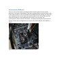
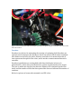
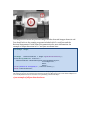
Gear Tooth Sensor
Gear tooth sensors are designed to be mounted adjacent to spinning ferrous gear
or sprocket teeth and detect whenever a tooth passes. The gear tooth sensor is a
Hall-effect device that uses a magnet and solid state device that can measure
changes in the field caused by the passing teeth.
The picture below shows a gear tooth sensor mounted on a VEX robot chassis
measuring a metal gear rotation. Notice that a metal gear is attached to the plastic
gear. The gear tooth sensor needs a ferrous material passing by it to detect rotation.
Figure 11: Gear tooth sensor with a ferrous gear cemented to the plastic Vex gear so the gear tooth senor would
detect the rotation.
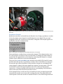
Encoders
Encoders are devices for measuring the rotation of a spinning shaft. Encoders are
typically used to measure the distance a wheel has turned, which can be translated
into distance traveled by the robot. Distance traveled over a measured period of
time represents the speed of the robot, and is another common measurement for
encoders.
Encoders typically have a rotating disk with slots which spins in front of a
photodetector. As the slots pass the detector, pulses are generated on the output.
The rate at which the slots pass the detector indicates the rotational speed of the
shaft, and the number of slots that have passed the detector indicates the number of
rotations.
Below is a picture of an encoder mounted on a VEX robot:
Figure 12: A Grayhill quadrature optical encoder. Note the two connectors, one for the A channel and one for the
B channel.
Quadrature Encoders
Quadrature encoders are handled by the Encoder class. Using a quadrature encoder
is done by simply connecting the A and B channels to two digital I/O ports and
assigning them in the constructor for Encoder. A diagram of the output signals of a
quadrature encoder is shown below.
Figure 13: Quadrature encoder phase relationships between the two channels.
Some quadrature encoders have an extra index channel. This channel pulses once
for each complete revolution of the encoder shaft. If counting the index channel is
required for the application it can be done by connecting that channel to a simple
Counter object which has no direction information.
There are four QuadratureEncoder modules in the cRIO’s FPGA and 8 Counter
modules that can operate as quadrature encoders. One of the differences between
the encoder and counter hardware is that encoders can give an oversampled 4X
count using all 4 edges of the input signal, but counters can only return a 1X or 2X
result based on one of the input signals. If 1X or 2X is chosen in the Encoder
constructor, a Counter module is used with lower oversampling. If 4X (default) is
chosen, then one of the four FPGA encoders is used.
In the example below, 1 and 2 are the port numbers for the two digital inputs and
true tells the encoder to not invert the counting direction. The sensed direction
could depend on how the encoder is mounted relative to the shaft being measured.
The k4X makes sure that an encoder module from the FPGA is used and 4X accuracy
is obtained. To get the 4X value you should use the GetRaw() method on the
encoder. The Get() method will always return the normalized value by dividing
the actual count obtained by the 1X, 2X, or 4X multiplier.
Encoder encoder(1, 2, true, k4X);
Example 8:
C++ code creating an encoder on ports 1 and 2 with reverse sensing and 4X encoding.
Encoder encoder;
encoder = new Encoder(1, 2, true, EncodingType.k4X);
Example 9:
Java code craeating an encoder on ports 1 and 2 with reverse sensing and 4X encoding.
Analog Inputs
The NI 9201 Analog to Digital module has a number of features not available on
simpler controllers. It will automatically sample the analog channels in a roundrobin fashion, providing a combined sample rate of 500 ks/s (500,000 samples /
second). These channels can be optionally oversampled and averaged to provide the
value that is used by the program. There are raw integer and floating point voltage
outputs available in addition to the averaged values. The diagram below outlines
this process.
Figure 14: Analog Input System
When the system averages a number of samples, the division results in a fractional
part of the answer that is lost in producing the integer valued result. Oversampling
is a technique where extra samples are summed, but not divided down to produce
the average. Suppose the system were oversampling by 16 times – that would mean
that the values returned were actually 16 times the average. Using the oversampled
value gives additional precision in the returned value. The oversample and average
engine equations are shown below.
oversample bits
average bits
Figure 15: Oversample and Average Engine Equations
To set the number of oversampled and averaged values use the methods in the
examples below:
void SetAverageBits(UINT32 bits);
UINT32 GetAverageBits();
void SetOversampleBits(UINT32 bits);
UINT32 GetOversampleBits();
Example 10: C++ methods for setting oversampling and averaging on an analog to digital converter.
void setAverageBits(int bits);
UINT32 getAverageBits();
void setOversampleBits(UINT32 bits);
UINT32 getOversampleBits();
Example 11: Java methods for setting oversampling and averaging on an analog to digital converter.
The number of averaged and oversampled values are always powers of two
(number of bits of oversampling/averaging). Therefore the number of oversampled
or averaged values is two bits, where ‘bits’ is passed to the methods:
SetOversampleBits(bits) and SetAverageBits(bits). The actual rate
that values are produced from the analog input channel is reduced by the number of
averaged and oversampled values. For example, setting the number of oversampled
bits to 4 and the average bits to 2 would reduce the number of delivered samples by
16x and 4x, or 64.
The sample rate is fixed per analog I/O module, so all the channels on a given
module must sample at the same rate. However, the averaging and oversampling
rates can be changed for each channel. The WPI Robotics Library will allow the
sample rate to be changed once for a module. Changing it to a different value will
result in a runtime error being generated. The use of some sensors (currently just
the Gyro) will set the sample rate to a specific value for the module it is connected
to.
Analog Triggers
Figure 16: Analog Trigger
Figure 17: 3 Point Average Reject Filter
Controlling Actuators
This section discusses the control of motors and pneumatics through speed
controllers, relays, and WPILib methods. The overall structure of this section is
shown in the chart below.
Actuators
Motors
Victors
Jaguars
Pneumatics
Servos
RobotDrive
Solenoids
Relays
Figure 18: Actuator section organization
Motors
The WPI Robotics library has extensive support for motor control. There are a
number of classes that represent different types of speed controllers and servos.
The WPI Robotics Library currently supports two classes of speed controllers,
PWM-based motor controllers (Jaguars or Victors) and servos, but is also designed
to support non-PWM motor controllers that will be available in the future. In
addition, while not actually an actuator, the RobotDrive class handles standard 2
motor, 4 motor, and Mecanum drive bases incorporating either Jaguar or Victor
speed controllers.
Motor speed controllers take speed values in floating point numbers that range from
-1.0 to +1.0. The value of -1.0 represents full speed in one direction, 1.0 represents
full speed in the other direction, and 0.0 represents stopped. Motors can also be set
to disabled, where the signal is no longer sent to the speed controller.
There are a number of motor controlling classes included in WPILib. These classes
are given in the table below:
Type
PWM
Victor
Usage
Base class for all the pwm-based speed controllers and servos
Speed controller with a 10ms update rate, supplied by Innovation
First, commonly used in robotics competitions.
Jaguar
Advanced speed controller used for 2009 and future FRC
competitions with a 5ms update rate.
Servo
Class designed to control small hobby servos as typically supplied
in the FIRST kit of parts.
RobotDrive General purpose class for controlling a robot drive train with either
2 or 4 drive motors. It provides high level operations like turning. It
does this by controlling all the robot drive motors in a coordinated
way. It’s useful for both autonomous and tele-operated driving.
Table 5: Types of motor control
PWM
The PWM class is the base class for devices that operate on PWM signals and is the
connection to the PWM signal generation hardware in the cRIO. It is not intended to
be used directly on a speed controller or servo. The PWM class has shared code for
Victor, Jaguar, and Servo subclasses that set the update rate, deadband elimination,
and profile shaping of the output signal.
Victor
The Victor class represents the Victor speed controllers provided by Innovation
First. They have a minimum 10ms update period and only take a PWM control
signal. The minimum and maximum values that will drive the Victor speed control
vary from one unit to the next. You can fine tune the values for a particular speed
controller by using a simple program that steps the values up and down in single
raw unit increments. You need the following values from a victor:
Value
Max
DeadbandMax
Center
DeadbandMin
Min
Description
The maximum value where the motors stop changing speed
and the light on the Victor goes to full green.
The value where the motor just stops operating.
The value that is in the center of the deadband that turns off
the motors.
The value where the motor just starts running in the opposite
direction.
The minimum value (highest speed in opposite direction)
where the motors stop changing speed.
Table 6: Necessary information about Victors
With these values, call the SetBounds method on the created Victor object.
void SetBounds(INT32 max,
INT32 deadbandMax,
INT32 center,
INT32 deadbandMin,
INT32 min);
Example 12: A C++ method for setting the bounds on a Victor object.
Jaguar
The Jaguar class supports the Texas Instruments Jaguar speed controller. It has an
update period of slightly greater than 5ms and currently uses only PWM output
signals. In the future the more sophisticated Jaguar speed controllers might have
other methods for control of its many extended functions.
The input values for the Jaguar range from -1.0 to 1.0 for full speed in either
direction with 0 representing stopped.
Use of limit switches
TODO
Example
TODO
Servo
The Servo class supports the Hitechnic servos supplied by FIRST. They have a 20ms
update period and are controlled by PWM output signals.
The input values for the Servo range from 0.0 to 1.0 for full rotation in one direction
to full rotation in the opposite direction. There is also a method to set the servo
angle based on the (currently) fixed minimum and maximum angle values.
For example, the following code fragment rotates a servo through its full range in 10
steps:
Servo servo(3);
float servoRange = servo.GetMaxAngle() - servo.GetMinAngle();
for (float angle = servo.GetMinAngle();
angle < servo.GetMaxAngle();
angle += servoRange / 10.0)
{
servo.SetAngle(angle);
// set servo to angle
Wait(1.0);
// wait 1 second
}
Example 13: C++ example that rotates a servo through its full range in 10 steps.
RobotDrive
The RobotDrive class is designed to simplify the operation of the drive motors
based on a model of the drive train configuration. The idea is to describe the layout
of the motors. Then the class can generate all the speed values to operate the motors
for different situations. For cases that fit the model, it provides a significant
simplification to standard driving code. For more complex cases that aren’t directly
supported by the RobotDrive class it may be subclassed to add additional features
or not used at all.
First, create a RobotDrive object specifying the left and right Jaguar motor
controllers on the robot, as shown below.
RobotDrive drive(1, 2);
// left, right motors on ports 1,2
Example 14: Creating a Robot drive object in C or Java.
Or
RobotDrive drive(1, 2, 3, 4);
// four motor drive configuration
Example 15: Creating a robot drive object with 4 motors.
This sets up the class for a 2 motor configuration or a 4 motor configuration.
There are additional methods that can be called to modify the behavior of the
setup.
SetInvertedMotor(kFrontLeftMotor, true);
Example 16: Inverting the motor direction in C++.
This sets the operation of the front left motor to be inverted. This might be
necessary depending on the setup of your drive train.
Once set up, there are methods that can help with driving the robot either from the
Driver Station controls or through programmed operations. These methods are
described in the table below.
Method
Drive(speed, turn)
TankDrive(leftStick,
rightStick)
ArcadeDrive(stick)
HolonomicDrive(magnitud
e, direction, rotation)
SetLeftRightMotorSpeeds
(leftSpeed, rightSpeed)
Description
Designed to take speed and turn values ranging
from -1.0 to 1.0. The speed values set the robot
overall drive speed; with positive values
representing forward and negative values
representing backwards. The turn value tries to
specify constant radius turns for any drive speed.
Negative values represent left turns and the
positive values represent right turns.
Takes two joysticks and controls the robot with
tank steering using the y-axis of each joystick.
There are also methods that allow you to specify
which axis is used from each stick.
Takes a joystick and controls the robot with
arcade (single stick) steering using the y-axis of
the joystick for forward/backward speed and the
x-axis of the joystick for turns. There are also
other methods that allow you to specify different
joystick axes.
Takes floating point values, the first two are a
direction vector the robot should drive in. The
third parameter, rotation, is the independent rate
of rotation while the robot is driving. This is
intended for robots with 4 Mecanum wheels
independently controlled.
Takes two values for the left and right motor
speeds. As with all the other methods, this will
control the motors as defined by the constructor.
Table 7: C++ options for driving a robot. The Java methods are the same except with leading lower case
characters.
The Drive method of the RobotDrive class is designed to support feedback based
driving. Suppose you want the robot to drive in a straight line despite physical
variations in its parts and external forces. There are a number of strategies, but two
examples are using gear tooth sensors or a gyro. In either case an error value is
generated that tells how far from straight the robot is currently tracking. This error
value (positive for one direction and negative for the other) can be scaled and used
directly with the turn argument of the Drive method. This causes the robot to turn
back to straight with a correction that is proportional to the error – the larger the
error, the greater the turn.
By default the RobotDrive class assumes that Jaguar speed controllers are used. To
use Victor speed controllers, create the Victor objects then call the RobotDrive
constructor passing it pointers or references to the Victor objects rather than port
numbers.
Example TODO
Relays
The cRIO provides the connections necessary to wire IFI spikes via the relay outputs
on the digital breakout board. The breakout board provides a total of sixteen
outputs, eight forward and eight reverse. The forward output signal is sent over the
pin farthest from the edge of the sidecar, labeled as output A, while the reverse
signal output is sent over the center pin, labeled output B. The final pin is a ground
connection.
When a Relay object is created in WPILib, its constructor takes a channel and
direction, or a slot, channel and direction. The slot is the slot number that the digital
module is plugged into (the digital module being what the digital sidecar is
connected to on the cRIO) – this parameter is not needed if only the first digital
module is being used. The channel is the number of the connection being used on
the digital sidecar. The direction can be kBothDirections (two direction
solenoid), kForwardOnly (uses only the forward pin), or kReverseOnly (uses
only the reverse pin). If a value is not input for direction, it defaults to
kBothDirections. This determines which methods in the Relay class can be
used with a particular instance of the object. The methods included in the relay class
are shown in the table below.
Method
void Set(Value value)
void
SetDirection(Direction
direction)
Description
This method sets the the state of the relay –
Valid inputs:
All Directions: kOff – turns off the Relay
kForwardOnly or kReverseOnly: kOn – turns on
forward or reverse of relay, depending on
direction
kForwardOnly: kForward – set the relay to
forward
kReverseOnly: kReverse – set the relay to
reverse
Sets the direction of the relay – Valid inputs:
kBothDirections: Allows the relay to use both the
forward and reverse pins on the channel
kForwardOnly: Allows relay to use only the
forward signal pin
kReverseOnly: Allows relay to use only the
reverse signal pin
Table 8: Relay class methods
In the example below, m_relay is initialized to be on channel 1. Since no
direction is specified, the direction is set to the default value of
kBothDirections. m_relay2 is initialized to channel 2, with a direction of
kForwardOnly. In the following line, m_relay is set to the direction of
kReverseOnly, and is then turned on, which results in the reverse output being
turned on. m_relay2 is then set to forward – since it is a forward only relay, this
has the same effect as setting it to on. After that, m_relay is turned off, a
command that turns off any active pins on the channel, regardless of direction.
Relay m_relay(1);
Relay m_relay2(2,Relay::kForwardOnly);
m_relay.SetDirection(Relay::kReverseOnly);
m_relay.Set(Relay::kOn);
m_relay2.Set(Relay::kForward);
m_relay.Set(Relay::kOff);
Example 17: C++ example of controlling relays using the Relay class.
Using the serial port
Using I2C
Pneumatics
Controlling pneumatics with WPILib is quite simple. The two classes you will
need are shown in the table below.
Class
Solenoid
Compressor
Purpose
Can control pneumatic actuators directly without the need for
an additional relay. (In the past a Spike relay was required
along with a digital output port to control a pneumatics
component.)
Keeps the pneumatics system charged by using a pressure
switch and software to turn the compressor on and off as
needed.
Table 9: Classes for controlling pneumatics
Compressor
The Compressor class is designed to operate the FRC supplied compressor on the
robot. A Compressor object is constructed with 2 input/output ports:
The Digital output port connected to the Spike relay that controls the
power to the compressor. (A digital output or Solenoid module port alone
doesn’t supply enough current to operate the compressor.)
The Digital input port connected to the pressure switch that monitors the
accumulator pressure.
The Compressor class will automatically create a task that runs in the
background twice a second and turns the compressor on or off based on the
pressure switch value. If the system pressure is above the high set point, the
compressor turns off. If the pressure is below the low set point, the compressor
turns on.
To use the Compressor class create an instance of the Compressor object and use
the Start() method. This is typically done in the constructor for your Robot
Program. Once started, it will continue to run on its own with no further
programming necessary. If you do have an application where the compressor should
be turned off, possibly during some particular phase of the game play, you can stop
and restart the compressor using the Stop() and Start() methods.
The compressor class will create instances of the DigitalInput and Relay
objects internally to read the pressure switch and operate the Spike relay.
For example, suppose you had a compressor and a Spike relay connected to Relay
port 2 and the pressure switch connected to digital input port 4. Both of these ports
are connected to the primary digital input module. You could create and start the
compressor running in the constructor of your RobotBase derived object using the
following 2 lines of code:
Compressor *c = new Compressor(4, 2);
c->Start();
Example 18: Starting the compressor in a C++ program fragment.
In the example above, the variable c is a pointer to a compressor object and the
object is allocated using the new operator. If it were allocated as a local variable
in the constructor, at the end of the constructor function its local variables would
be deallocated and the compressor would stop operating.
C++ Object Life Span
You need the Compressor object to last the entire match. If you allocate it with
new, the best practice is to store the pointer in a member variable, then delete it
in the Robot’s destructor, as shown in the example below:
class RobotDemo : public SimpleRobot
{
Compressor *m_compressor;
public:
RobotDemo()
{
m_compressor = new Compressor(4, 2);
m_compressor->Start();
}
~RobotDemo()
{
delete m_compressor;
}
}
Example 19: Making the compressor run for the entire match in a C++ program.
Alternatively, you can declare it as a member object then initialize and Start() it
in the Robot’s constructor. In this case you need to use the constructor’s
“initialization list” to initialize the Compressor object. The C++ compiler will
quietly give RobotDemo a destructor that deletes the Compressor object.
In Java you would accomplish the same thing as follows:
TODO: add Java example here
Solenoid
The Solenoid object controls the outputs of the NI 9472 Digital Output Module. It
is designed to apply an input voltage to any of the 8 outputs. Each output can
provide up to 1A of current. The module is designed to operate 12v pneumatic
solenoids used on FIRST robots. This makes the use of relays unnecessary for
pneumatic solenoids.
The NI 9472 Digital Output Module does not provide enough current to operate a
motor or the compressor, so relays connected to Digital Sidecar digital outputs will
still be required for those applications.
The port numbers on the Solenoid class range from 1-8 as printed on the
pneumatics breakout board.
The NI 9472 indicator lights are numbered 0-7 for the 8 ports, which is different
numbering than used by the class or the pneumatic bumper case silkscreening.
Setting the output values of the Solenoid objects to true or false will turn the outputs
on and off respectively. The following code fragment will create 8 Solenoid objects,
initialize each to true (on), and then turn them off, one per second. Then it turns
them each back on, one per second, and deletes the objects. You can observe the
operation of the Solenoid class by looking at the indicator lights on the 9472
module.
Solenoid *s[8];
for (int i = 0; i < 8; i++)
s[i] = new Solenoid(i + 1);
for (int i = 0; i < 8; i++)
{
s[i]->Set(true);
//
}
Wait(1.0);
for (int i = 0; i < 8; i++)
{
s[i]->Set(false);
//
Wait(1.0);
}
for (int i = 0; i < 8; i++)
{
s[i]->Set(true);
//
Wait(1.0);
delete s[i];
//
}
// allocate the Solenoid objects
turn them all on
turn them each off in turn
turn them back on in turn
delete the objects
Example 20: Controlling Solenoids in a C++ program fragment.
Getting Feedback from the Driver Station
The driver station is constantly communicating with the robot controller. You
can read the driver station values of the attached joysticks, digital inputs, analog
inputs, and write to the digital outputs. In addition there is Enhanced I/O
provided through the Cypress module. The DriverStation class has methods for
reading and writing everything connected to it, including joysticks. There is
another object, Joystick that provides a more convenient set of methods for
dealing with joysticks and other HID controllers connected to the USB ports. The
general relationships of feedback from the driver station are shown in the chart
below. The enhanced I/O is provided through an additional class called
DriverStationEnhancedIO. This class has methods for reading and writing
all the I/O options on the Cypress module as well as configuring it.
Feedback
To robot
Regular I/O
Joysticks
Enhanced I/O
From robot
Dashboard
output
Video
Digital and
analog inputs
Figure 19: Feedback section organization
Getting Data from the Digital and Analog Ports
Building a driver station with just joysticks is simple and easy to do, especially
with the range of HID USB devices supported by the Microsoft Windows based
driver station. Custom interfaces can be constructed and implemented using the
digital and analog I/O on the driver station. Switches can be connected to the
digital inputs, the digital outputs can drive indicators, and the analog inputs can
read various sensors, like potentiometers. Here are some examples of custom
interfaces that are possible:
Set of switches to set various autonomous modes and options
Potentiometers on a model of an arm to control the actual arm on the
robot
Rotary switches with a different resistor at each position to generate
unique voltage to effectively add more switch inputs
Three pushbutton switches to set an elevator to one of three heights
automatically
These custom interfaces often give the robot better control than is available from
a standard joystick or controller.
You can read/write the driver station analog and digital I/O using the following
DriverStation methods:
Method
Description
float GetAnalogIn(UINT32 channel)
Read an analog input value
connected to port channel
Read a digital input value
connected to port channel
Write a digital output value
on port channel
Read the currently set digital
output value on port channel
bool GetDigitalIn(UINT32 channel)
void SetDigitalOut(UINT32 channel,
bool value)
bool GetDigitalOut(UINT32 channel)
Table 10: Using the driver station analog and digital I/O
Other Driver Station Features
The Driver Station is constantly communicating with the Field Management
System (FMS) and provides additional status information through that
connection:
Method
bool IsDisabled()
bool IsAutonomous();
bool IsOperatorControl();
UINT32 GetPacketNumber();
Alliance GetAlliance();
UINT32 GetLocation();
float GetBatteryVoltage();
Description
Robot state
Field state (autonomous vs. teleop)
Field state
Sequence number of the current driver
station received data packet
Alliance (red, blue) for the match
Starting field position of the robot (1, 2, or
3)
Battery voltage on the robot
Table 11: Communicating with the FMS
Joysticks
The standard input device supported by the WPI Robotics Library is a USB joystick.
The 2009 kit joystick comes equipped with eleven digital input buttons and three
analog axes, and interfaces with the robot through the Joystick class. The Joystick
class itself supports five analog and twelve digital inputs – which allows for joysticks
with more capabilities.
The joystick must be connected to one of the four available USB ports on the driver
station. The startup routine will read whatever position the joysticks are in as the
center position, therefore, when the station is turned on the joysticks must be at
their center position. The constructor takes either the port number the joystick is
plugged into, followed by the number of axes and then the number of buttons, or
just the port number from the driver’s station. The former is primarily for use in
sub-classing (For example, to create a class or a non-kit joystick), and the latter for a
standard kit joystick.
The following example would create a default joystick called driveJoy on USB port 1
of the driver station. Something like a Microsoft Sidewinder joystick (which has five
analog axes and eight buttons) – which would be a good candidate for a subclass of
Joystick.
Joystick driveJoy(1);
Joystick opJoy(2,5,8);
Example 21: Creating a default Joystick object.
There are two methods to access the axes of the joystick. Each input axis is labeled
as the X, Y, Z, Throttle, or Twist axis. For the kit joystick, the applicable axis are
labeled correctly; a non-kit joystick will require testing to determine which axes
correspond to which degrees of freedom.
Each of these axes has an associated accessor; the X axis from driveJoy in the above
example could be read by calling driveJoy.GetX(); the twist and throttle axes
are accessed by driveJoy.GetTwist() and driveJoy.GetThrottle(),
respectively.
Alternatively, the axes can be accessed via the the GetAxis() and GetRawAxis()
methods. GetAxis() takes an AxisType – kXAxis, kYAxis, kZAxis,
kTwistAxis, or kThrottleAxis – and returns that axis’ value. GetRawAxis()
takes a number (1-6) and returns the value of the axis associated with that number.
These numbers are reconfigurable and are generally used with custom control
systems, since the other two methods reliably return the same data for a given axis.
There are three ways to access the top button (defaulted to button 2) and trigger
(button 1). The first is to use their respective accessor methods – GetTop() and
GetTrigger(), which return a true or false value based on whether the button is
currently being pressed. A second method is to call GetButton(), which takes a
ButtonType which can be either kTopButton or kTriggerButton. The last
method is one that allows access to the state of every button on the joystick –
GetRawButton(). This method takes a number corresponding to a button on the
joystick (see diagram below), and return the state of that button.
Figure 20: Diagram of a USB joystick
In addition to the standard method of accessing the Cartesian coordinates (x and
y axes) of the joystick’s position, WPILib also has the ability to return the position
of the joystick as a magnitude and direction. To access the magnitude, the
GetMagnitude() method can be called, and to access the direction, either
GetDirectionDegrees() or GetDirectionRadians() can be called. (See
the example below)
Joystick driveJoy(1);
Jaguar leftControl(1);
Jaguar rightControl(2);
if(driveJoy.GetTrigger())
//If the trigger is pressed
{
//Have the left motor get input from Y axis
//and the right motor get input from X axis
leftControl.Set(driveJoy.GetY());
rightControl.Set(driveJoy.GetAxis(kXAxis));
}
else if(driveJoy.GetRawButton(2))
//If button number 2 pressed (top)
{
//Have both right and left motors get input
//from the throttle axis
leftControl.Set(driveJoy.GetThrottle());
rightControl.Set(driveJoy.GetAxis(kThrottleAxis));
}
//If button number 4 is pressed
else if(driveJoy.GetRawButton(4))
//If button number 4 is pressed
{
//Have the left motor get input from the
//magnitude of the joystick’s position
leftControl.Set(driveJoy.GetMagnitude());
}
Example 22: Using buttons to determine how to interpret the joystick inputs.
Enhanced I/O through the Cypress Module
There are additional I/O options available through the Cypress module extended
I/O class. The module contains:
An accelerometer
Analog inputs
Analog outputs
A button
A status LED
Digital inputs
Digital outputs
PWM outputs
Fixed digital output
Encoder inputs with index
Touch sensor
PWM outputs
All these are accessible through the DriverStationEnhancedIO class. The class is a
singleton, i.e. there is never more than a single instance of it in the system. You can
get a reference to the class through the DriverStation object as shown:
DriverStationEnhancedIO &dseio =
DriverStation.GetInstance().GetEnhancedIO();
Example 23: Getting a reference to the DriverStationEnhancedIO object in C++
DriverStationEnhancedIO dseio =
DriverStation.getInstance().getEnhancedIO();
Example 24: Getting a reference to the DriverStationEnhancedIO object in Java
Once you have a reference to the DriverStationEnhancedIO object you can call any of
the methods that are available. For example, reading the touchpad slider is done
with the following method (assuming you already have an instance as described
above).
double slider = dseio.GetTouchSlider();
Example 25: Getting the value of the touchpad slider on the Cypress module in C++
double slider = dseio.getTouchSlider();
Example 26: Getting the value of the touchpad slider on the Cypress module in Java
Configuring the Enhanced I/O
The enhanced I/O features of the Cypress module can be configured either:
in your C++ or Java program
using the driver station I/O configuration screen
Either way that the configuration is set, the driver station records the configuration
and remembers the settings. Whenever the dashboard starts up it first reads the
configuration file, then the program settings are applied. This makes it convenient to
set up the dashboard using the control panel. However programs counting on
settings made on a specific dashboard won’t work if the dashboard is swapped for
another one.
Enhanced I/O data
The Enhanced I/O module has a very powerful and expanded set of capabilities
beyond just simple analog and digital I/O. Here are some of the available options:
Function
Accelerometer
Analog inputs
Analog outputs
Button state
LED output
Digital input
Digital output
PWM outputs
Quadrature
encoder input
Information
Returns acceleration in Gs
Analog inputs using a 3.3V reference either as a voltage or in
ratiometric form
2 channels (either A01 or A02) of analog output. About 0-3V
and about 100uA of drive current
Get the state of either the button on the board or 5 additional
configurable buttons
Set the state of any of 8 LEDs
Read digital input values for switches, etc.
Set digital output lines
2 pairs of I/O lines capable of PWM output. There is a PWM
generator for each pair. Pairs have common periods but
independent duty cycles.
There are 2 signed 16 bit 4X quadrature encoder inputs with
optional index functionality.
Capacitive touch
slider
There is a touch sensitive capacitive slider on the board.
Returns value between 0-1 with -1 indicating no touch.
Sending data to the dashboard
Often it is desirable to get feedback from the robot back to the drivers. The
communications protocol between the robot and the driver station includes
provisions for sending program specific data. The program at the driver station that
receives the data is called the dashboard. A default dashboard program is supplied
with the driver station. The default dashboard program displays:
Analog port values
Digital I/O port values
Solenoids
Relays
Camera tracking data
The data values are sent in groups called Clusters to correspond to the clusters on
the LabVIEW dashboard program. The data is sent in two groups, high priority and
low priority. The high priority data is sent first, then errors, then low priority data.
On any given update only the high priority data might get transmitted, but on
subsequent updates it might all get through. In the default dashboard the camera
data is sent as high priority and the port data is sent as low priority.
Adding dashboard data to your robot program
There is a sample program called DashboardDataExample included with the
Workbench and NetBeans distributions. Look at those samples to get an idea of how
to add custom data to your programs. The data structures being sent correspond to
the LabVIEW dashboard client program at the driver station. Looking at the data
model while looking at the sample program will make it clear as to how to
customize the dashboard or write your own. The left structure is the I/O port data
and the right structure is the camera tracking data.
2010 Camera and Image Processing
New for 2010 there is a new API to access the camera and the related image
processing classes. Java implements the new API and the C++ library includes both
the new and the old APIs. Access to the camera and all the image types are now
objects and can be accessed using methods on the appropriate object type.
Using the camera
The camera is accessed through the AxisCamera class. It is a singleton, meaning that
you can get an instance of the AxisCamera using the static method GetInstance() in
C++ or getInstance() in Java. Methods on the camera object can be used to set
various parameters on the camera to programmatically control its operation.
Typically your robot program would retrieve image from the camera and process
them. Here is a portion of a program that retrieves images and performs some
processing on them.
HSLImage image;
// Create and set up a camera instance
AxisCamera &camera = AxisCamera::getInstance();
camera.writeResolution(k160x120);
camera.writeBrightness(0);
Wait(3.0);
// loop getting images from the camera and finding targets
while (IsOperatorControl())
{
// Get a camera image
camera.GetImage(image.image);
// do something with image here
.
.
.
}
Example 27: A C++ program that sets up the camera, gets images, and processes them. Notice how the
HSLImage object is used with the camera.
The camera supports video back to the dashboard. When your dashboard program
does a network connection to the PCVideoServer object on the robot, a stream of
JPEG images will be sent back to the dashboard. The sample LabVIEW dashboard
application will make connections to the video server and you will be able to see
what the robot camera is seeing in real-time as it is driving in your lab or in
competition. Once you retrieve an instance of the camera the server will be
automatically available for video back to the dashboard. You don’t have to write any
code to enable this.
Working with images
There are a number of image classes that represent the types of images that are
supported by the NI IMAQ (Image Acquisition) library. For each image type there
are methods that can be called to do various operations on the image. Cascading
these image operations together is the way to do more complex operations such as
target recognition.
A good way to prototype image processing code is to use the NI Vision Assistant that
is included with the FRC Software DVD. Images taken with the FRC camera can be
saved to disk. Then using the Vision Assistant you can try different operations with
varying parameters you set and will show the result of each operation. You can
cascade a number of image operations together and see the result of them
combined. Once it is working on a number of test images then it is easy to write the
corresponding code and add it to your robot program. Here is an example of
cascading a Color Threshold and a Particle Analysis:
All of the sample images shown in this section were produced using the Vision
Assistant.
Use of image memory
In Java images are stored using C++ data structures and only pointers are
manipulated, all the actual processing is done at the C/C++ level for optimum
performance. For example, a threshold operation on a color image it is actually
performed by C code and the image itself is stored as a C data structure. This is to
prevent unnecessary copies from C/C++ to Java for large image structures.
In C++ the actual IMAQ image is stored as a member of the corresponding image
object. Whenever new images are produced as a result of an operation, for example,
returning a BinaryImage as the result of a threshold operation, a pointer
(BinaryImage*) is returned from the C++ method. It is the responsibility of the
caller to free the newly allocated image when finished with it. Be sure to delete
the image objects when you are finished using them. See the example programs
supplied with the C++ FRC Toolkit for more information.
Image types
There are a number of image types available, each used for a different purpose.
Image
ColorImage
HSLImage
RGBImage
MonoImage
BinaryImage
This shows the hierarchy diagram of the types of images and the class relationships between them.
Image is the base class for all other image types. If provides height and width
accessor methods that work across all image types.
ColorImage is the basic color image type and can either be a HSLImage or an
RGBImage representing the two most commonly used image formats. ColorImage
objects have three planes each representing some part of the total image. In an
RGBImage, the three planes represent the red, green, and blue values that make up
the total picture.
MonoImage objects represent a single color. BinaryImage objects have a single
bit for each pixel. They are often the result of a color or edge detection operation on
a ColorImage. For example looking for objects of a particular color might use a
threshold operation on a ColorImage resulting in a BinaryImage with each set
pixel corresponding to a pixel in the ColorImage.
Common ColorImage operations
Once you have a ColorImage (either HSLImage or RGBImage) there are a
number of operations that can be done it. Most of these operations results in a new
image of the same size.
Threshold detection
Threshold detection takes a three ranges corresponding to the three color planes in
the image type. A BinaryImage is returned where each pixel that is on in the
BinaryImage corresponds to a pixel in the ColorImage that was within the
threshold range.
Locating color targets from the 2009 Lunacy game consists of finding the pink and
green targets and making sure they were one over the other in the right order. Using
a threshold operation to detect only the pink portion of the image is done using a set
of values that correspond to the pink color found on the targets. The result is a
bitmap (BinaryImage) that represents the pixel locations in the original images
that represent the matching colors.
Image
ColorImage operation
This is the original image taken using the
FRC camera.
This is the resultant bitmap with just the
pixels that matched the pink threshold
values.
One of the easiest ways to determine the
threshold values is using the Vision
assistant. You can tune the 6 color
parameters to find a set that results in the
best discrimination of the image being
tested. Then those parameters can be
copied into your program to do the
detection in the robot.
Here you can see graphs that represent
the values of Hue, Saturation, and
Luminance in the original color image and
the min-max values that are the
parameters to the threshold operation.
You can manipulate the values to see the
effectiveness of the parameters changing.
The code to do this threshold operation is shown below:
Threshold pinkThreshold(226, 255, 28, 255, 96, 255);
HSLImage *targetImage = new HSLImage(“/testImage.png”); // create image
BinaryImage *pinkPixels = targetImage->thresholdHSL(pinkThreshold);
This code produces a BinaryImage object using the threshold ranges shown. You can
see how the values are taken from the Vision Assistant window above.
Plane extraction and replacement
There are a number of methods that will extract a single plane from a color image.
The meaning of the plane will depend on the type of the image. For example in a
RGB (red-green-blue) image the second plane is the green plane and represents all
the green values. In an HSL image, the second plane is the saturation value for the
image. You can extract any type of plane from any type of image. For example, if you
have an RGBImage object, you can still extract the luminance plane by calling the
GetLuminancePlane() method in C++ or the getLuminancePlane() method in Java.
Above are two images, the first a color image taken with the camera on the robot as
recorded by the driver station. The second image was produced by extracting the
luminance plane from the first image leaving only greyscale.
Ellipse detection
Ellipse detection is one type of shape detection available for use with the camera.
Ellipse detection is a single IMAQ library call even though internally it does many
steps to find ellipses. This method is available on MonoImage objects. Detecting
ellipses from camera images that are color (either RBGImage or HSLImage)
require extraction of a single plane. Typically the luminance plane is used since it
makes the detection less effected by color changes.
Ellipse detection is very flexible and has a number of options that you might want to
use to change the effectiveness of the detection.
The image above shows the previous image with the detected images shown in red.
You should refer to the sample programs included with C++ and Java and the
National Instruments Vision library documentation for more information. An
example of ellipse detection in C++ and Java are shown here:
ColorImage *image;
.
.
.
MonoImage *luminancePlane = image->getLuminancePlane();
vector<EllipseMatch> *results =
luminancePlane->DetectEllipses(&ellipseDescriptor,
&curveOptions,
NULL,
NULL);
printf("Found %d ellipses\n", results->size());
delete luminancePlane;
Example 28: Ellipse detection taken from one of the C++ sample programs provided with the C++ FRC toolkit.
The luminance plane is extracted from the ColorImage producing a MonoImage. The results of DetectEllipses is a
vector of EllipseMatch structures with each one representing one detected ellipse.
<java example of ellipse detection here>
Miscellaneous
This section discusses more advanced control of your robot, such as with PID
programming. The structure of this section is outlined in the chart below.
Miscellaneous
Control (PID)
Multitasking
Timing
Figure 21: Miscellaneous section organization
PID Programming
PID controllers are a powerful and widely used implementation of closed loop
control. The PIDController class allows for a PID control loop to be created
easily, and runs the control loop in a separate thread at consistent intervals. The
PIDController automatically checks a PIDSource for feedback and writes to a
PIDOutput every loop. Sensors suitable for use with PIDController in WPILib
are already subclasses of PIDSource. Additional sensors and custom feedback
methods are supported through creating new subclasses of PIDSource. Jaguars
and Victors are already configured as subclasses of PIDOutput, and custom
outputs may also be created by sub-classing PIDOutput.
The following example shows how to create a PIDController to set the position
of a turret to a position related to the x-axis on a joystick. This turret uses a single
motor on a Jaguar, and a potentiometer for angle feedback. As the joystick X value
changes, the motor should drive to a position related to that new value. The
PIDController class will ensure that the motion is smooth and stops at the right
point.
A potentiometer that turns with the turret will provide feedback of the turret angle.
The potentiometer is connected to an analog input and will return values ranging
from 0-5V from full clockwise to full counterclockwise motion of the turret. The
joystick X-axis returns values from -1.0 to 1.0 for full left to full right. We need to
scale the joystick values to match the 0-5V values from the potentiometer. This can
be done with the following expression:
(turretStick.GetX() + 1.0) * 2.5
Example 29:
Example of scaling Joysticks in C++.
The scaled value can then be used to change the setpoint of the control loop as
the joystick is moved.
The 0.1, 0.001, and 0.0 values are the Proportional, Integral, and Differential
coefficients respectively. The AnalogChannel object is already a subclass of
PIDSource and returns the voltage as the control value and the Jaguar object is a
subclass of PIDOutput.
Joystick turretStick(1);
Jaguar turretMotor(1);
AnalogChannel turretPot(1);
PIDController turretControl(0.1, 0.001, 0.0, &turretPot, &turretMotor);
turretControl.Enable();
// start calculating PIDOutput values
while(IsOperator())
{
turretControl.SetSetpoint((turretStick.GetX() + 1.0) * 2.5);
Wait(.02);
// wait for new joystick values
}
Example 30: Using the PIDController object.
The PIDController object will automatically (in the background):
Read the PIDSource object (in this case the turretPot analog input)
Compute the new result value
Set the PIDOutput object (in this case the turretMotor)
This will be repeated periodically in the background by the PIDController. The
default repeat rate is 50ms although this can be changed by adding a parameter
with the time to the end of the PIDController argument list. See the reference
document for details.
Multitasking (C++)
There are a number of classes in the C++ version of WPILib to aid in creating
programs that use concurrent programming techniques. The underlying operating
system, VxWorks has a full support for multitasking, but the classes simplify
programming for the more common cases.
Creating tasks
A task is a thread of execution in a program that runs concurrently with other tasks
in a program. Each task has a number of attributes including a name and priority.
Tasks share memory with each other. To create a task you write a function that
should is the starting point for that thread of execution. Using the Task class you can
run that function as a separate task. Creating an instance of Task looks like this:
Task myTask(“taskname”, (FUNCPTR) functionToStart);
The task name will be seen in the task list in Workbench when you are debugging
the program. The functionToStart is the name of a function to run when the task is
started. FUNCPTR is a typedef that defines the type (signature) of the function. The
task is started using the Start() method.
myTask.Start();
Once started, the function will run asynchronously along with the other tasks in the
system.
Synchronizing tasks
Starting tasks is easy – and for many cases that’s all that’s required. A good example
is the Compressor class. The compressor class creates a task that simply loops
checking the pressure switch and operating the compressor relay. It doesn’t interact
with other tasks and doesn’t really share data with the rest of the program.
The difficulties with multitasking come in when there is data that’s shared between
two tasks. If one task is writing to the data and gets half of it written, then the reader
task starts up, it will find inconsistent data. Only half of the data will have been
changed and that can cause very hard to track down problems in your code. An
example is the Camera class. It’s reading camera images in one task and your
program is consuming them in a different task. If the consumer tries to read an
image while the camera is writing it, half the image will be new and the other half
will be old. Not a good situation!
VxWorks provides a facility to help this called a Semaphore. Semaphores let you
synchronize access to data ensuring that only one task will have access to it at a
time. You lock the block of data, read or write it, then unlock it. While it’s locked, any
other task trying to access it will have to wait until it’s unlocked. WPILib has a class
called Synchronized that simplifies the use of semaphores for this purpose. It is
modeled after the Java style of synchronization.
The model for synchronizing data access is to first create a semaphore that will be
used. Here is an example from the AnalogModule class in WPILib.
static SEM_ID m_registerWindowSemaphore;
Then to protect access to data using the semaphore, create a new block with a
Synchronized object on the first line.
INT16 AnalogModule::GetValue(UINT32 channel)
{
INT16 value;
CheckAnalogChannel(channel);
tAI::tReadSelect readSelect;
readSelect.Channel = channel - 1;
readSelect.Module = SlotToIndex(m_slot);
readSelect.Averaged = false;
{
Synchronized sync(m_registerWindowSemaphore);
m_module->writeReadSelect(readSelect, &status);
m_module->strobeLatchOutput(&status);
value = (INT16) m_module->readOutput(&status);
}
wpi_assertCleanStatus(status);
return value;
}
This will “take” the semaphore, declaring that this piece of code owns the associated
data. Access the data inside the block, and when the block exits, the synchronized
object will be automatically freed by C++ and the semaphore will be released
allowing access from other parts of your code.
You should use the same semaphore in all the places where you write code that
access that protected data.
Timers
Timers provide a means of timing events in your program. For example, your
program can start a timer, wait for an even to happen, then read the timer value as a
way of determine the elapsed time. The Timer class can get the time value as well as
start, stop, and reset the current time associated with that timer.
Notification
There is a facility in WPILib to let you do regular timed operations. The Notifier
class will run a function that you write after a period of time or at regular intervals.
The function runs as a separate task and is started with optional context
information. An example is the PIDController class which requires calculations
to be done on a regular basis. It creates a Notifier object using the function to be
called.
m_controlLoop = new Notifier(PIDController::CallCalculate, this);
Then when it is time to start the function running, in this case CallCalculate
from the PIDController class, it does it using the StartPeriodic() method.
m_controlLoop->StartPeriodic(m_period);
The CallCalculate method will be called every m_period seconds (typically
the period is a fraction of a second). You can also have single instance notification –
the notifier function is only called one time after the interval, using the
StartSingle() method. Periodic notification can also be stopped by calling the
Stop() method on the Notifier.
System Architecture
This section describes how the system is put together and how the libraries
interact with the base hardware. It should give you better insight as to how the
whole system works and its capabilities.
Digital Sources
Figure 22: Digital source breakdown
Digital Filter
Figure 23: Digital filter diagram and example
Contributing to the WPI Robotics Library
TODO: fill In this sction
Appendix A: 2009 Camera and Vision
TODO: the captions appear to be incorrect in this chapter. Compare them with
the original document and fix as necessary.
Camera
The camera provided in the 2009 kit is the Axis 206. The C camera API provides
initialization, control and image acquisition functionality. Image appearance
properties are configured when the camera is started. Camera sensor properties
can be configured with a separate call to the camera, which should occur before
camera startup. The API also provides a way to update sensor properties using a
text file on the cRIO. PcVideoServer.cpp provides a C++ API that serves images to
the dashboard running on a PC. There is a sample dashboard application as part
of the LabVIEW distribution that can interface with C and C++ programs.
Camera task management
A stand-alone task, called FRC_Camera, is responsible for initializing the camera
and acquiring images. It continuously runs alongside your program acquiring
images. It needs to be started in the robot code if the camera is to be used.
Normally the task is left running, but if desired it may be stopped. The activity of
image acquisition may also be controlled, for example if you only want to use the
camera in Autonomous mode, you may either call StopCameraTask() to end the
task or call StopImageAcquisition() to leave the task running but not reading
images from the camera.
Camera sensor property configuration
ConfigureCamera () sends a string to the camera that updates sensor properties.
GetCameraSetting () queries the camera sensor properties. The properties that
may be updated are listed below along with their out-of-the-box defaults:
brightness =50
whitebalance=auto
exposure=auto
exposurepriority=auto
colorlevel=99
sharpness=0
GetImageSetting() queries the camera image appearance properties (see the
Camera Initialization section below). Examples of property configuration and
query calls are below:
// set a property
ConfigureCamera(“whitebalance=fixedfluor1”);
// query a sensorproperty
char responseString[1024];
// create string
bzero (responseString, 1024);
// initialize string
if (GetCameraSetting(“whitebalance”,responseString)=-1) {
printf(“no response from camera \n);
} else {printf(“whitebalance: %s \n”,responseString);}
// query an appearance property
if (GetImageSetting(“resolution”,responseString)=-1) {
printf(“no response from camera \n);
} else {printf(“resolution: %s \n”,responseString);}
Example 31: The example program CameraDemo.cpp will configure properties in a variety of ways and take
snapshots that may be FTP’d from the cRIO for analysis.
Sensor property configuration using a text file
The utility ProcessFile() sets obtain camera sensor configuration specified from a
file called “cameraConfig.txt” on the cRIO. ProcessFile() is called the first time
with 0 lineNumber to get the number of lines to read. On subsequent calls each
lineNumber is requested to get one camera parameter. There should be one
property=value entry on each line, i.e. “exposure=auto” A sample
cameraConfig.txt file is included with the CameraDemo project. This file must be
placed on the root directory of the cRIO. Below is an example file:
#######################
! lines starting with ! or # or comments
! this a sample configuration file
! only sensor properties may be set using this file
! – set appearance properties when StartCameraTask() is called
#######################
exposure=auto
colorlevel=99
Simple Camera initialization
StartCameraTask() initializes the camera to serve MJPEG images using the
following camera appearance defaults:
Frame Rate = 10 frames / sec
Compression = 0
Resolution = 160x120
Rotation = 0
if (StartCameraTask() == -1) {
dprintf( LOG_ERROR, “Failed to spawn camera task; Error code %s”,
GetErrorText(GetLastError()) );
}
Example 32:
C++ program showing how to initialize the camera.
Configurable Camera initialization
Image processing places a load on the cRIO which may or may not interfere with
your other robot code. Depending on needed speed and accuracy of image
processing, it is useful to configure the camera for performance. The highest
frame rates may acquire images faster than your processing code can process
them, especially with higher resolution images. If your camera mount is upside
down or sideways, adjusting the Image Rotation in the start task command will
compensate and images will look the same as if the camera was mounted right
side up. Once the camera is initialized, it begins saving images to an area of
memory accessible by other programs. The images are saved both in the raw
(JPEG) format and in a decoded format (Image) used by the NI image processing
functions. An example is shown below.
int frameRate = 15;
// valid values
int compression = 0;
// valid values
ImageSize resolution = k160x120;
// k160x120,
ImageRotation rot = ROT_180;
// ROT_0,
0 - 30
0 – 100
k320x240, k640x480
ROT_180
StartCameraTask(frameRate, compression, resolution, rot);
Example 33:
C++ program showing how to save images.
Image Acquisition
Images of types IMAQ_IMAGE_HSL, IMAQ_IMAGE_RGB, and IMAQ_IMAGE_U8
(gray scale) may be acquired from the camera. To obtain an image for
processing, first create the image structure and then call GetImage() to get the
image and the time that it was received from the camera:
double timestamp;
// timestamp of image returned
Image* cameraImage = frcCreateImage(IMAQ_IMAGE_HSL);
if (!cameraImage) { printf(“error: %s”, GetErrorText(GetLastError()) };
if ( !GetImage(cameraImage, ×tamp) ) {
printf(“error: %s”, GetErrorText(GetLastError()) };
Example 34: Getting images from the camera.
reads the most recent image, regardless of whether it has been
previously accessed. Your code can check the timestamp to see if it’s an image
you already processed.
GetImage()
Alternatively, GetImageBlocking() will wait until a new image is available if the
current one has already been served. To prevent excessive blocking time, the call
will return unsuccessfully if a new image is not available in 0.5 second. This is
shown in the example below.
Image* cameraImage = frcCreateImage(IMAQ_IMAGE_HSL);
double timestamp;
// timestamp of image returned
double lastImageTimestamp; // timestamp of last image, to ensure image is
new
int success = GetImageBlocking(cameraImage, ×tamp,
lastImageTimestamp);
Example 35: Getting images from the camera.
Camera Metrics
Various camera instrumentation counters used internally may be accessed that
may be useful for camera performance analysis and error detection. Here is a list
of the metrics:
CAM_STARTS, CAM_STOPS, CAM_NUM_IMAGE, CAM_BUFFERS_WRITTEN,
CAM_BLOCKING_COUNT, CAM_SOCKET_OPEN, CAM_SOCKET_INIT_ATTEMPTS,
CAM_BLOCKING_TIMEOUT, CAM_GETIMAGE_SUCCESS, CAM_GETIMAGE_FAILURE,
CAM_STALE_IMAGE, CAM_GETIMAGE_BEFORE_INIT,
CAM_GETIMAGE_BEFORE_AVAILABLE, CAM_READ_JPEG_FAILURE,
CAM_PC_SOCKET_OPEN, CAM_PC_SENDIMGAGE_SUCCESS,
CAM_PC_SENDIMAGE_FAILURE, CAM_PID_SIGNAL_ERR, CAM_BAD_IMAGE_SIZE,
CAM_HEADER_ERROR
The following example call gets the number of images served by the camera:
int result = GetCameraMetric(CAM_NUM_IMAGE);
Example 36:
Retrieving the image number.
Images to PC
The class PCVideoServer, when instantiated, creates a separate task that sends
images to the PC for display on a dashboard application. The sample program
DashboardDemo shows an example of use.
StartCameraTask();
PCVideoServer pc;
pc.Stop();
pc.Start();
Example 37:
// Initialize the camera
// The constructor starts the image server task
// Stop image server task
// Restart task and serve images again
Sending images to the PC dashboard program.
To use this code with the LabVIEW dashboard, the PC must be configured as IP
address 10.x.x.6 to correspond with the cRIO address 10.x.x.2.
Vision / Image Processing
Access to National Instrument’s nivison library for machine vision enables
automated image processing for color identification, tracking and analysis. The
VisionAPI.cpp file provides open source C wrappers to a subset of the proprietary
library. The full specification for the simplified FRC Vision programming
interface is in the FRC Vision API Specification document, which is in the
WindRiver\docs\extensions\FRC directory of the Wind River installation with this
document. The FRC Vision interface also includes high level calls for color
tracking (TrackingAPI.cpp). Programmers may also call directly into the low
level library by including nivision.h and using calls documented in the NI Vision
for LabWindows/CVI User Manual.
Naming conventions for the vision processing wrappers are slightly different from
the rest of WPILib. C routines prefixed with “imaq” belong to NI’s LabVIEW/CVI
vision library. Routines prefixed with “frc” are simplified interfaces to the vision
library provided by BAE Systems for FIRST Robotics Competition use.
Sample programs provided include SimpleTracker, which in autonomous mode
tracks a color and drives toward it, VisionServoDemo, which also tracks a color with
a two-servo gimbal. VisionDemo demonstrates other capabilities including storing a
JPEG image to the cRIO, and DashboardDemo sends images to the PC Dashboard
application.
Image files may be read and written to the cRIO non-volatile memory. File types
supported are PNG, JPEG, JPEG2000, TIFF, AIDB, and BMP. Images may also be
obtained from the Axis 206 camera. Using the FRC Vision API, images may be copied,
cropped, or scaled larger/smaller. The intensity measurement functions available
include calculating a histogram for color or intensity and obtaining values by pixel.
Contrast may be improved by equalizing the image. Specific color planes may be
extracted. Thresholding and filtering based on color and intensity characteristics
are used to separate particles that meet specified criteria. These particles may then
be analyzed to find the characteristics.
Color Tracking
High level calls provide color tracking capability without having to call directly
into the image processing routines. You can either specify a hue range and light
setting, or pick specific ranges for hue, saturation and luminance for target
detection.
Example 1: Using Defaults
Call GetTrackingData() with a color and type of lighting to obtain default ranges
that can be used in the call to FindColor(). The ParticleAnalysisReport returned
by FindColor() specifies details of the largest particle of the targeted color.
TrackingThreshold tdata = GetTrackingData(BLUE, FLUORESCENT);
ParticleAnalysisReport par;
if (FindColor(IMAQ_HSL, &tdata.hue, &tdata.saturation,
&tdata.luminance, &par)
{
printf(“color found at x = %i, y = %i”,
par.center_mass_x_normalized, par.center_mass_y_normalized);
printf(“color as percent of image: %d”,
par.particleToImagePercent);
}
Example 38:
Color tracking example.
The normalized center of mass of the target color is a range from –1.0 to 1.0,
regardless of image size. This value may be used to drive the robot toward a
target.
Example 2: Using Specified Ranges
To manage your own values for the color and light ranges, you simply create
Range objects as shown in the example below.
Range hue, sat, lum;
hue.minValue
hue.maxValue
sat.minValue
sat.maxValue
lum.minValue
lum.maxValue
=
=
=
=
=
=
140;
// Hue
155;
100;
// Saturation
255;
40; // Luminance
255;
FindColor(IMAQ_HSL, &hue, &sat, &lum, &par);
Example 39: Using specified ranges of colors to limit the found color values.
Tracking also works using the Red, Green, Blue (RGB) color space, however HSL
gives more consistent results for a given target.
Example 3: Using Return Values
Here is an example program that enables the robot to drive towards a green
target. When it is too close or too far, the robot stops driving. Steering like this is
quite simple as shown in the example below.
The following declarations in the class are used for the example:
RobotDrive *myRobot
Range greenHue, greenSat, greenLum;
Example 40:
C++ program declarations.
This is the initialization of the RobotDrive object, the camera and the colors for
tracking the target. It would typically go in the RobotBase derived constructor.
if (StartCameraTask() == -1) {
printf( “Failed to spawn camera task; Error code %s”,
GetErrorText(GetLastError()) );
}
myRobot = new RobotDrive(1, 2);
// values for tracking a target - may need tweaking in your environment
greenHue.minValue = 65; greenHue.maxValue = 80;
greenSat.minValue = 100; greenSat.maxValue = 255;
greenLum.minValue = 100; greenLum.maxValue = 255;
Example 41:
C++ program showing the use of return values.
Here is the code that actually drives the robot in the autonomous period. The
code checks if the color was found in the scene and that it was not too big (close)
and not too small (far). If it is within the limits, the robot is driven forward full
speed (1.0), and with a turn rate determined by the center_mass_x_normalized
value of the particle analysis report.
The center_mass_x_normalized value is 0.0 if the object is in the center of the
frame; otherwise it varies between -1.0 and 1.0 depending on how far off to the
sides it is. That is the same range as the Drive method uses for the turn value. If the
robot is correcting in the wrong direction then simply negate the turn value.
Example 4: Two Color Tracking
An example of tracking a two color target is in the demo project TwoColorTrackDemo.
The file Target.cpp in this project provides an API for searching for this type of target.
The example below first creates tracking data:
while (IsAutonomous())
{
if ( FindColor(IMAQ_HSL, &greenHue, &greenSat, &greenLum, &par)
&& par.particleToImagePercent < MAX_PARTICLE_TO_IMAGE_PERCENT
&& par.particleToImagePercent > MIN_PARTICLE_TO_IMAGE_PERCENT )
{
myRobot->Drive(1.0, (float)par.center_mass_x_normalized);
}
else myRobot->Drive(0.0, 0.0);
Wait(0.05);
}
myRobot->Drive(0.0, 0.0);
Example 42:
Autonomous color tracking and driving the robot towards the target.
// PINK
sprintf (td1.name, “PINK”);
td1.hue.minValue = 220;
td1.hue.maxValue = 255;
td1.saturation.minValue = 75;
td1.saturation.maxValue = 255;
td1.luminance.minValue = 85;
td1.luminance.maxValue = 255;
// GREEN
sprintf (td2.name, “GREEN”);
td2.hue.minValue = 55;
td2.hue.maxValue = 125;
td2.saturation.minValue = 58;
td2.saturation.maxValue = 255;
td2.luminance.minValue = 92;
td2.luminance.maxValue = 255;
Example 43:
Typical color values for the green and pink targets.
Call FindTwoColors() with the two sets of tracking data and an orientation (ABOVE,
BELOW, RIGHT, LEFT) to obtain two ParticleAnalysisReports which have details of a
two-color target.
Note: The FindTwoColors API code is in the demo project, not in the WPILib project
// find a two color target
if (FindTwoColors(td1, td2, ABOVE, &par1, &par) {
// Average the two particle centers to get center x & y of combined
target
horizontalDestination = (par1.center_mass_x_normalized +
par2.center_mass_x_normalized) / 2;
verticalDestination = (par1.center_mass_y_normalized +
par2.center_mass_y_normalized) / 2;
{
Example 44:
Finding a 2 color target.
To obtain the center of the combined target, average the x and y values. As
before, use the normalized values to work within a range of -1.0 to +1.0. Use the
center_mass_x and center_mass_y values if the exact pixel position is desired.
Several parameters for adjusting the search criteria are provided in the Target.h
header file (again, provided in the TwoColorTrackDemo project, not WPILib). The
initial settings for all of these parameters are very open to maximize target
recognition. Depending on your test results you may want to adjust these, but
remember that the lighting conditions at the event may give different results. These
parameters include:
FRC_MINIMUM_PIXELS_FOR_TARGET – (default 5) Make this larger to
prevent extra processing of very small targets.
FRC_ALIGNMENT_SCALE – (default 3.0) scaling factor to determine
alignment. To ensure one target is exactly above the other, use a smaller
number. However, light shining directly on the target causes significant
variation, so this parameter is best left fairly high.
FRC_MAX_IMAGE_SEPARATION (default 20) Number of pixels that can
exist separating the two colors. Best number varies with image resolution.
It would normally be very low but is set to a higher number to allow for
glare or incomplete recognition of the color.
FRC_SIZE_FACTOR (default 3) Size difference between the two particles.
With this setting, one particle can be three times the size of the other.
FRC_MAX_HITS (default 10) Number of particles of each color to analyze.
Normally the target would be found in the first (largest) particles. Reduce
this to increase performance, Increase it to maximize the chance of
detecting a target on the other side of the field.
FRC_COLOR_TO_IMAGE_PERCENT (default 0.001) One color particle
must be at least this percent of the image.