1
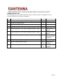
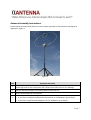
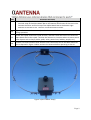
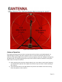
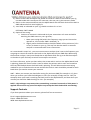
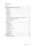
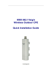
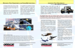
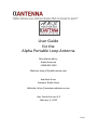
User Guide
for the
Alpha Portable Loop Antenna
Manufactured by:
Alpha Antenna
1.888.482.3249
Website: http://AlphaAntenna.com
Available from:
Amateur Radio Store
Website: https://amateurradiostore.com
User Guide Version 3.2
February 3, 2015
Page 1
Table of Contents
Introduction .................................................................................................................................... 3
Product Overview ........................................................................................................................... 3
Safety Tips ....................................................................................................................................... 4
Antenna Diagram ............................................................................................................................ 5
Antenna Parts List ........................................................................................................................... 6
Antenna Assembly Instructions ...................................................................................................... 7
Antenna Operation ....................................................................................................................... 10
Support Contacts .......................................................................................................................... 11
Page 2
Introduction
Thank you for purchasing the Alpha Micro-Tune Loop Antenna. We hope that you will enjoy
using this product, as we continue to receive written testimonials from Amateur Radio
Operators (Hams) who are surprised by the antenna’s ability to make many long distance
contacts, using low power.
The Alpha Loop is a magnetic loop antenna that is easy to tune, has acceptable bandwidths, and
offers coverage for 40, 30, 20, 17, 15, 12, & 10 meter bands. The antenna is only 34 inches in
diameter and has a built in tuner at the base of the antenna. This antenna is so efficient that it
can be used indoors, from a porch or balcony with only a 2-3db reduction in performance.
Finally, if you require assistance assembling or using this product, please do not hesitate to call
us at 1-888-482-3249 or send email to: [email protected]
Product Overview
The Alpha Micro-Tune Loop Antenna is designed to operate on the 10, 12, 15, 17, 20, 30, and 40
Meter amateur radio bands. It will accept up to 30 Watts (PEP) of transmitter power on SSB.
Using the antenna’s Micro-Tuner, your radio’s transmission line SWR can be continuously tuned
to a match of less than 1.5:1 on any frequency from the 10 Meter through the 40 Meter band.
When manufacturing this antenna, we use only brass bolts and nuts at the connection points
that feed the antenna, as well as silver plated shield and gold plated pin connectors at the feed
point of the antenna. We then place the Alpha Match inside a High Voltage UL-Rated housing.
We put safety first and insert a nylon shaft between the knob on the front of the Alpha Match
and the 6:1 reduction drive that connects to the Variable Air Capacitor, which is designed to
keep RF burns from occurring. This design also helps to minimize your body’s capacitive
interference when tuning the Alpha Loop.
Additional Product Details
• Antenna Weight: 1.5 pounds
• Tripod Weight: 3 pounds
• Bag Weight: .25 pounds
• Antenna Configuration: Circular Loop
• Frequency Coverage: 7 MHz to 29.7 MHz
• Maximum Power Rating: 30 Watts PEP SSB
• Height to top of Alpha Loop (if mounted on tripod):
o Minimum; Approximately 6 Feet
o Maximum; Approximately 9 ½ Feet
Page 3
Safety Tips
When installing or operating this antenna or any other antenna/tower, please observe the
following safety tips.
NOTE – High voltages are present when transmitting, no matter how much or little power is
applied. Do not touch any part of the Alpha Loop while transmitting.
WARNING: INSTALLATION OR OPERATION OF THIS PRODUCT NEAR POWER LINES IS
DANGEROUS! FOR YOUR SAFETY, FOLLOW THE ENCLOSED INSTALLATION DIRECTIONS. THOUGH
THIS ANTENNA IS CONSTRUCTED OF INSULATED WIRE, PROPER CARE MUST BE TAKEN DURING
INSTALLATION. INSTALLER ASSUMES ALL LIABILITY FOR PROPERTY AND LIFE SAFETY.
YOU, YOUR ANTENNA, AND SAFETY
Each year, hundreds of people are killed, mutilated, or receive severe and permanent injuries
when attempting to install an antenna. In many of these cases, the victim was aware of the
danger of electrocution, but did not take adequate steps to avoid the hazard. For your safety,
and to help you achieve a good installation, please READ and FOLLOW the safety precautions
below. THEY MAY SAVE YOUR LIFE!
1. If you are installing an antenna for the first time, please, for your own safety as well as
others, seek PROFESSIONAL ASSISTANCE.
2. Select your installation site with safety, as well as performance, in mind. REMEMBER:
ELECTRIC POWER LINES AND PHONE LINES LOOK ALIKE. FOR YOUR SAFETY, ASSUME THAT ANY
OVERHEAD LINES CAN KILL YOU.
3. Call your electric power company. Tell them your plans and ask them to come take a look at
your proposed installation. This is a small inconvenience, considering YOUR LIFE IS AT STAKE.
4. Plan your installation procedure carefully and completely before you begin. Successful raising
of a mast or tower is largely a matter of coordination. Each person should be assigned a specific
task, and should know what to do and when to do it. One person should be designated as the
leader/coordinator of the operation to call out instructions and watch for signs of trouble.
5. When installing your antenna, REMEMBER: DO NOT USE A METAL LADDER. DO NOT WORK
ON A WET OR WINDY DAY. DO DRESS PROPERLY: shoes with rubber soles and heels, rubber
gloves, long sleeved shirt or jacket.
6. If the assembly starts to drop, get away from it and let it fall. Remember, the antenna, mast,
cable and metal guy wires are all excellent conductors of electrical current. Even the slightest
touch of any of these parts to a power line completes an electrical path through the antenna
and the installer – THAT’S YOU!
7. If ANY PART of the antenna system should come in contact with a power line, DON’T TOUCH
IT OR TRY TO REMOVE IT YOURSELF. CALL YOUR LOCAL POWER COMPANY. They will remove
it safely. If an accident should occur with the power lines, call for qualified emergency help
IMMEDIATELY.
Page 4
Antenna Diagram
The major components of the antenna, and their relative positions, are depicted in Figure 1.
Figure 1
Page 5
Antenna Parts List
The following parts are included with this antenna. Please contact our support line if you
discover that parts are missing or damaged.
Item
Description
Qty.
Comment
1
Black Canvas Carry Bag with Shoulder Strap
1
2
Tripod with integrate Mast
1
3
Black Feed Line Box with SO-239 Connector
1
4
Grey Alpha Match Box
1
5
Circular Aluminum “Inner Loop” Antenna Element – Small
1
Used for 10-12
Meters
6
Circular Aluminum “Inner Loop” Antenna Element – Large
1
Used for 15-40
Meters
7
Curved Aluminum “Outer Loop” Antenna Elements – Long
4
1 from each side
removed for 1012 Meters
8
Curved Aluminum “Outer Loop” Antenna Elements – Short
2
9
Screws – Stainless Steel 1 x 6/32
Min.
20
Additional are
included
10
Wing Nuts – Stainless Steel 6/32
Min.
20
Additional are
included
Page 6
Antenna Assembly Instructions
Please follow the steps listed below to assure proper operation of this antenna and deploy as
depicted in Figure 2.
Figure 2
Step
Assembly Operation
1
Remove all items from the Canvas Carry Bag and carefully cut open the reusable 6 Mil
plastic bag some of the components are in and inspect each item for any damage.
2
Identify and count all parts, comparing them to the Parts List.
3
Set the tripod aside, for the moment.
4
Determine your initial operating requirements:
• If you plan to configure and operate the antenna on 15-40 Meters, go to Step 5
• If you plan to operate and configure it for 10-12 Meters, go to Step 8.
Page 7
Step
Assembly Operation
5
To configure the antenna for operation on 15-40 Meters, attach each end of the Large
“Inner Loop” Antenna to the two terminal straps located on the Black Feed Line Box
using four screws and nuts as depicted in Figure 4 below. Set this assembled piece to
the side, for the moment.
6
Now, assemble the Outer Loop Antenna as depicted in Figure 4 below for 15-40 Meters
by first building two separate outer loop “semi-circles” consisting of:
• One long/curved outer loop element, fastened to one short/curved outer loop
element, fastened to one long/curved element.
• Use four screws and four nuts to (loosely) fasten the three antenna elements
together.
• Repeat this process to assemble the second semi-circle.
7
This completes the partial assembly of the antenna for operation on 15-40 Meters.
Go to Step 12.
8
To configure the antenna for operation on 10-12 Meters, attach each end of the Small
“Inner Loop” Antenna as depicted in Figure 3 below to the two terminal straps located
on the Black Feed Line Box using four screws and nuts. Set this assembled piece to the
side, for the moment.
9
Now, assemble the Outer Loop Antenna for 10-12 Meters as depicted in Figure 3 below
by building two separate outer loop “semi-circles” consisting of:
• One long/curved outer loop element, fastened to one short/curved outer loop
element.
• Use two screws and two nuts to (loosely) fasten the two antenna elements together.
• Repeat this process to assemble the second semi-circle.
10
This completes the partial assembly of the antenna for operation on 10-12 Meters.
Go to Step 12.
11
Continue the final assembly steps for either the 15-40 Meter or 10-12 Meter antenna by
attaching the Black Feed Line Box to the top of the two antenna semi-circles and by
attaching the Grey Alpha Match Box to the bottom of the two antenna semi-circles as
follows:
• Lay the two semi-circle antenna elements on a flat surface. Form them in the shape
of a circle but do not connect the top or bottom ends of the semicircles together.
• Locate the Black Feed Line Box and place it at the top and inside of the newly formed
antenna “circle”, with the box’s SO-239 connector facing downward (towards the
center of the antenna circle). Connect one terminal strap of the Black Feed Line Box
to the top left element of the semi-circle. Connect the other terminal strap of the
Black Feed Line Box to the top right element of the semi-circle. Use four screws and
nuts to fasten.
• Locate the Grey Alpha Match Box and place it at the bottom and inside of the
Page 8
Step
Assembly Operation
antenna “circle”, with the box’s tripod receptacle facing downward. Connect one
terminal strap of the Alpha Match Box to the bottom left element of the semi-circle.
Connect the other terminal strap of the Alpha Match Box to the bottom right
element of the semi-circle. Use four screws and nuts to fasten.
12
Tighten all screws and nuts securely so that the assembled antenna does not come apart
during operation.
13
Locate the tripod, extend the tripod sections, and then screw the base of the antenna’s
Alpha Match box to the tripod. Position the antenna in a location where it cannot touch
other objects such as lamps, desks, poles, wires, power lines, ladders, people, etc.).
14
Connect a PL-259 connector with 50 Ohm coax transmission line to the Black Feed Line
Box as depicted in Figure 1 above and test the antenna before operating on the air.
Figure 3 (10-12 Meter Setup)
Page 9
Figure 4 (15-40 Meter setup)
Antenna Operation
The Alpha Loop antenna has a built in tuning knob, which is black, on the Alpha Match, as
depicted Figure 1 above, and other images as well. It is with this knob that you tune the
antenna to the lowest SWR of less than 1.9:1 on any frequency from the 10 Meter through the
40 Meter band. The following technique has proven to be the easiest method for tuning the
Alpha Loop in nearly all scenarios:
1) After attaching your coax (per Step 14 above), turn your radio on and to the frequency
you would like to operate, then adjust the volume so you can hear it while standing at
the antenna.
2) Turn the black knob on the Alpha Match till you hear the loudest noise level coming
from the speaker on the antenna.
Page 10
3) Return to the radio and adjust the power to a level of 5 watts or less and set your rig
into AM mode and a maximum of 5 watts out, then set you rig into transmit mode.
4) Return to the antenna and fine tune the Alpha Match with the black knob till the built in
SWR Indicator bulb is most brightly lit.
5) Your SWR, as indicated on your rig, should now be at 3:1 or less.
OPTIONAL FINE TUNING
6) Optional fine tuning:
a. Continue to transmit in AM mode with your transmitter at 5 watts and while
watching the SWR meter on your rig either;
i. Move your tuning dial (within the frequency range you are licensed to
operate on, till minimum SWR is attained), or
ii. Slightly move the black knob on the Alpha Match till the minimum (1.5:1
or less) is shown on your rig. This step can also be used if an antenna
analyzer is connected rather than a transceiver.
As is mentioned in step 6.a.ii., you can use an antenna analyzer that is set to the frequency you
are going to transmit on and turn the knob on the Alpha Loop till your SWR dips. When using
the antenna analyzer, many have found that an A/B Switch with the rig on A and the analyzer
on B makes it quick and easy to switch from analysis to transmit.
For future reference, and as you learn where the arrow and tic mark on the Alpha Match knob
is pointing, please feel free to make a note for where the pointer and tic mark are located on
the front label behind where the black knob is pointing. This will allow an alternate tuning
method for you to find where the arrow and also the knob tic mark should be pointed for each
band when you need to retune your antenna.
HINT – When you remove your hand after tuning for minimum SWR (for example 1.4:1), then
when you remove your hand the SWR goes to 2.6:1 (for example). Simply tune for 2.6:1 (for
example) when your hand is touching the black knob on the Alpha Match, and then when you
remove your hand the SWR should go to 1.4:1 (for example).
NOTE – High voltages are present when transmitting, no matter how much or little power is
applied. Do not touch any part of the Alpha Loop except the black knob while transmitting.
Support Contacts
If you have questions about your antenna, please feel free to contact us.
Email: [email protected]
Phone: 1-888-482-3249
WEB: www.alphaantenna.com
Page 11