1
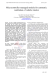
AN ACCELERATION MEASURING SYSTEM VIA
RADIO FREQUENCY COMMUNICATION
A Design Project Report
Presented to the Engineering Division of the Graduate School
Of Cornell University
In Partial Fulfillment of the Requirements for the Degree of
Master of Engineering (Electrical)
by
Wong, Kim Fung
Project Advisor: Dr. Bruce Land
Degree Date: January 2004
Abstract
Master of Electrical Engineering Program
Cornell University
Design Project Report
Project Title: An Acceleration Measuring System via Radio Frequency Communication
Author: Wong, Kim Fung
Abstract: This project is designed to explore the possibility of building a compact
acceleration measuring device and applying it in a typical middle/high school science
class. Such an interesting interactive device could to be used to improve the traditional
classroom environment. Students can carry the device on their bodies and see how fast
they move, and ideally, it is hoped to help them become more interested in learning
simple physics. The project’s design is based on a pair of microcontrollers.
Accelerometer’s sensors are used and data are transmitted through radio frequency and
serial communication (RS232). Readings of the accelerometer’s outputs are updated ten
times a second and data will be shown in graphical interpretation after measurement is
taken. The designed goal of this project is to provide a simple-to-use and reliable device
that can record the acceleration with good time resolution.
Report Approved by
Project Advisor: ____________________________________Date:__________________
i
Executive Summary
This Master of Electrical and Computer Engineering project is designed to
measure acceleration through a simple microcontroller based system. It explores the
possibility of performing a simple interactive experiment in a science class to help
students in learning basic physics. This system should be easy to use by any grade
teacher with a simple user manual.
Two dual-axis accelerometers are arranged to form a tri-axis accelerometer and
outputs are sent to an Atmel Mega32 microcontroller (MCU). The accelerometer’s
outputs are analog. They are converted into digital counts by the built-in MCU analogto-digital converters. The radio connection is established by a pair of radio packet
controllers (SP2) from Radiometrix. For both remote end’s hardware and base station’s
hardware, radio packet controllers are connected to MCUs. Acceleration readings are
sent from the remote end’s radio packet controller to the base station’s radio packet
controller. After performing some mathematics on the receiving data, the acceleration
readings in digital count are converted into percentage and they are sent through a serial
communication to a computer. Then Matlab is used to display the data into a graphical
interpretation.
This system functions as a point-to-point system, but the SP2s are capable of
being applied as a point-to-multipoint system. The SP2 has the handshaking and
collision avoidance mechanism to prevent data loss during transmission. It can also be
customized to include source and designation address in the packet. However, the cost
would need to be lowered for production use.
The planning and implementation of this project have gone well and smoothly.
Planning was carefully thought through from the beginning of design and it was worth
the time since a careful plan saves a lot development time. The final deliverable is fairly
compact and solid. Data transmission between the pair of radio packet controllers is
robust. Accuracy of accelerometers is acceptable. Overall, the system functions well and
works as desired.
ii
Table of Contents
An Acceleration Measuring System via Radio Frequency Communication
Abstract…………………………………………………………………………………...i
Executive Summary……………………………………………………………………...ii
1) Introduction………………………………………………………………………1
2) Design Problem and System Requirements………………………………….....2
2.1 Design Problem………………...………………………………………………...2
2.2 System Requirements……………………………………………………………..2
3) Range of solutions………………………………………………………………..3
3.1 Microcontroller…..……………………………………….………………….......3
3.2 Wireless Connection………………………………………………………….…...3
3.3 Accelerometer…………………………………………………………………....4
3.4 Data Processing…………………………………………………………………..4
4) Design and Implementation……………………………………………………..5
4.1 Remote end hardware……………………………………………………………..5
4.2 Base station hardware……………………………………………………………11
4.3 Embedded program…………………………………………………………….13
4.4 Matlab application………………………………………………………………17
5) Test Results………………………………………………………….…………..18
6) Conclusion………………………………………………………………………20
7) Acknowledgements……………………………………………………………..21
Appendix A: Cost……………………….………………………………….……….22
Appendix B: Schematics…………………..………………………………………..23
Appendix C: Remote end microcontroller’s Code………………………………..25
Appendix D: Base station microcontroller’s Code………….……………………33
Appendix E: Matlab Code…………………………………………………………38
Appendix F: Matlab result…………………………………………………………40
Appendix G: User’s Manual…...………………..…………………………………45
Appendix H: Picture……………..…………………………………………………46
Appendix I: Bibliography……….…………………………………………………49
1) Introduction
Traditional learning method in classroom environment is not always enjoyable.
While some children do fine in learning fundamental physics with traditional way, there
are always others who prefer interactive learning. This project explores the possibility of
building a compact and reliable acceleration measuring device with cost effective
solution. Its goal is to provide students a tool to enhance their learning experience in
classroom.
In fulfilling the Master of Engineering project requirement, I chose to design a
system based on microcontroller. This gives me a chance to build a tangible and practical
deliverable rather than just some abstract fancy programming. In addition to this, I was
able to apply both hardware knowledge and software programming skill into the project.
Using radio packet controller for the wireless connection in this design gives
advantages such as longer reliable range, lower cost, and most importantly, the possibility
of extending the project’s goal into a small personal network with multiple client systems.
The accelerometers can be easily replaced with any desired acceleration range and only a
little modification is needed to be done on the embedded programs.
One of the main goals of this project is simplicity. The system should be reliable
and a friendly, easy to understand result should be available to user. Hence, the final data
is in a matrix form so that it will be easy to import into software, such as Excel or Matlab.
A user manual is provided in Appendix G to show how to get a graphical interpretation of
collected data in Matlab.
1
2) Design Problem and System Requirements
2.1 Design Problem
The goal of this project is to design a low cost, compact and reliable acceleration
measuring device. It should also be expandable into multiple clients system with few
code modifications. A simple graphical interpretation should be available to analysis the
collected data.
The system is composed with two major hardware and they are remote end’s
hardware and base station’s hardware. Remote end’s hardware is responsible in
collecting analog signals from accelerometers, converting signals into digital count by
built-in ADC, arranging data into packet, and sending the packet to the base station’s
hardware. Base station’s hardware is responsible in receiving packet, rearranging the
received data in percentage, and transmitting the rearranged data to a computer via
USART. Finally, data is analyzed in some graphs.
2.2 System Requirements
A simple-to-use and maintenance free system is the priority of this design. A
nearly plug-and-play system is designed with minimum user’s operational steps. After
discussing with Dr. Land, system requirements are as following:
•
For a given tight budget, cost needs to be kept low.
•
The device should be fairly compact since it would be carried on a human’s body.
•
Range of the radio frequency connection should be highly stable up 20m.
•
The system should be expandable with multiple clients if necessary.
•
Acceleration readings should be constantly updated at 10Hz.
•
A graphical interpretation should be available on the received readings.
•
No radio interference is allowed on other instruments.
2
3) Range of solutions
The initial project proposal is slightly different from what the deliverable is at the
end of implementation. Various components of the initial design have been replaced.
This could be a reason of better fit or just happened that the wanted components were
unavailable at the time of implementation. As some of the hardware had been changed
throughout the development, revisions on the design were constantly made. In the
following, four major components of the system are introduced.
3.1 Microcontroller
Atmel AVR microcontroller is chosen for this project because I am relatively
familiar with it. It has been used in ECE476-Microcontroller class which I had taken
during spring semester and general technical support is available from Dr. Land or
various websites. It is a good fit for the project as it includes eight built-in analog-todigital conversion channels, built-in USART, two external interrupts, and four bidirectional ports which are just enough for project development and debugging purpose.
3.2 Wireless Connection
Initial design was to apply Bluetooth technology instead of using radio packet
controller (SP2). After much research had been done, the cost of a pair of Bluetooth
module was from $300 to $400. The worse fact is that most modules can only support
point-to-point. It will be a while before the next generation point-to-multipoint OEM
modules are available. After discussing this with Dr. Land, we omitted the choice of
Bluetooth technology and chose to use radio packet controller.
At a cost of $198, the SP2 does give some advantages over Bluetooth modules
that are available. First and most important, multiple SP2 can form a small personal
network and each packet can include the source and destination address/ID. Second, SP2
includes handshake mechanism to prevent packet loss. Packet framing and error
checking is user transparent. Third, it has a reliable range of 50m in-building and 200m
outdoor.
3
3.3 Accelerometer
An initial design included an accelerometer of +/-10g with analog output. It was
hoped to fit the system into various application with a lager range. In addition to this, the
project is designed to measure all X-axis, Y-axis, and Z-axis. It is difficult to find a triaxis accelerometer with a suitable range since most accelerometers are designed for
industrial purpose. While most accelerometers are used in industries, the cost is not low.
As a result, only a dual-axis accelerometer of +/-2g with analog output is available to be
sampled from Analog Devices. During implementation, two dual-axis accelerometers are
arranged in a way that all three axes are perpendicular to each other. There is one axis of
an accelerometer is left disconnected from microcontroller.
3.4 Data Processing
Data are collected and processed in three stages and each stage can process the
information in different ways. It is entirely up to the developer on what data he wants to
have at each stage.
i)
Accelerometer’s outputs are analog and they are processed by
microcontroller’s ADC and then transmitted out.
ii)
Data received in base station’s hardware are manipulated to convert to
percentage. After some mathematical manipulation, the data before
transmitting through serial communication to a computer are in percentage of
+/-2g.
iii)
At the hyper terminal, data are arranged into a matrix with three columns.
After collecting the necessary data, a file is saved by capturing the matrix.
Then, a Matlab program is opened and the data is once again processed by the
program. At this final processing, data in percentage are converted into data
in unit g and this translation shows the real accelerations that have recorded.
This scheme of handling collected data in the above way eased the programming
effort and it will be elaborated later in this report.
4
4) Design and Implementation
The acceleration measuring system includes two major hardware and two major
software programs. The hardware is the remote end’s hardware and the base station’s
hardware. The software programs are the embedded application and Matlab program.
A block diagram of the system is shown below.
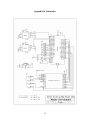
4.1 Remote end hardware
Remote end’s hardware is the device that will be carried by a user. Lots of efforts
have been spent to make it compact, light and reliable. Overall, the device consists of
three major parts and they are microcontroller, accelerometer, and radio packet controller.
All of the major components are elaborated in the following sections.
5
There is a color scheme used in this project and they are:
•
Red – 9V
•
Yellow – 5V
•
Black – ground
•
White – data signals between MCU and SP2 or X-axis
•
Blue – transmission related signals
•
Green – receiving related signals or Y-axis
•
Purple – Z-axis value
•
Orange – interconnection signals or reset
Microcontroller
Atmel AVR Mega32 is chosen for the project because of its availability, familiar
by the developer, and its great features such as built-in analog-to-digital converters,
external interrupts, and USART transmission.
•
Port A has eight channels of ADC. ADC0 is connected with X-axis of first
accelerometer. ADC1 is connected with Y-axis of first accelerometer. ADC2 is
connected with X-axis of second accelerometer that is held upright. As a result,
ADC2 is reading Z-axis value of the device.
•
Port B is connected with LEDs for testing and debugging purpose. These LEDs
help to debug the embedded program during development. It is almost impossible
to have program worked the first time without debugging and that is why it is
necessary to have these LEDs. They can be used to show the data transmitted, or
which state the microcontroller is at.
•
Port C is used to interface with a radio packet controller (SP2). PC6 is an output
signal connected with TXR’ of SP2. PC5 is an output signal connected with
RXA’. PC3, PC2, PC1, and PC0 are bi-directional signals connected with D3, D2,
D1, D0 of SP2 respectively.
6
•
Port D is also used to interface with SP2. PD2 is external interrupt zero and it is
an input signal connected with TXA’ from SP2. PD3 is external interrupt one and
it is an input signal connected with RXR’ from SP2. PD7 is an output signal
connected with Reset’ of SP2.
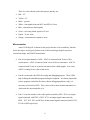
A table with the list of signals connected with the microcontroller is shown below:
Pin
Port
Direction
Signal
40
PA0
Input
X-axis
39
PA1
Input
Y-axis
38
PA2
Input
Z-axis
8:1
PB[7:0]
Output
Red LEDs
28
PC6
Output
TXR’
27
PC5
Output
RXA’
25:22
PC[3:0]
Bi-directional
D3,D2,D1,D0
21
PD7
Output
Reset’
17
PD1
Input
RXR’
16
PD0
Input
TXA’
Beside the Port signals, basic connections on microcontroller are worth noticing.
The microcontroller is running at 16MHz with an external crystal. A reset button is
available on microcontroller and the MCU’s reset is activated on low.
A 9V alkaline battery is used to power up this remote end’s hardware. Of course
there is a 5V voltage regulator connected with the battery. The voltage regulator is
LM78M05 of TO-220 package from National Instrument. A 0.1µF capacitor is
connected between Vcc and ground to stabilize the source. The prototype board that is
used is 0.1 inch spacing and it is the most popular standard for most components.
7
Accelerometer
Analog Devices ADXL311 +/- 2g dual-axis accelerometer is selected for this
project. It is operational from 2.7V to 5.25V. Its typical sensitivity is 312mv/g at 5V and
0g is about 2.5V. Notice that the typical sensitivity changes with different input voltage
and each accelerometer has different electrical characteristic.
Accelerometer’s output is in analog which is desired since the MCU has the builtin ADC. First, a 10-bit resolution is used for the AD conversion in which means 1023 is
the maximum digital count. Then the ADC data register is left shifted and the higher 8bit which is register ADCH is chosen. The measured analog signals from the
accelerometers are referenced with 5V supply voltage and the equation of getting digital
count of the analog signals is: X = 1023 * (Accelerometer’s signal level / 5V)
A list of the equivalent values of accelerometer’s output in different forms is
shown below:
In g
In voltage
Higher 8-bit digital count
2
3.124
10100000 = 0xA0
1
2.812
10010000 = 0x90
0
2.500
10000000 = 0x80
-1
2.188
01110000 = 0x70
-2
1.876
01100000 = 0x60
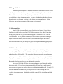
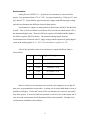
Since two dual-axis accelerometers are used, they are arranged in a way that all
three axes are perpendicular to each other. A strong wire is used to hold them as close as
possible at 90 degree. X-axis and Y-axis of first accelerometer are read as X-axis and Yaxis of the system. X-axis of second accelerometer is read as Z-axis of the system and Yaxis of second accelerometer is left disconnected from microcontroller. Example of an
accelerometer orientation is shown below:
8
Y-axis (-ve)
ADXL311
0309
X-axis (+ve)
X-axis (-ve)
Y-axis (+ve)
After carefully aligning and connecting them together, they are tested individually
since each accelerometer may differ from another on electrical characteristics. As a
result of this testing, the theoretical values of accelerometer’s outputs are neglected and
the practical values are derived.
In g
X-axis
Y-axis
Z-axis
2
0xA2
0x9D
0xA5
1
0x92
0x8D
0x95
0
0x82
0x7D
0x85
-1
0x72
0x6D
0x75
-2
0x62
0x5D
0x65
9
Radio Packet Controller
Radiometrix SP2-433-16 radio packet controller is chosen for the project. SP2 is
a highly intelligent transceiver module at 160kbps half duplex. It is operational at 5V and
is direct interface to 5V CMOS logic. It has a reliable 50m in-door and 200m outdoor
range. SP2 includes two modules internally. One is UHF module which is responsible to
transmit and receive data. The other is space port controller which is responsible to
control data and to interface with external microcontroller. Operational method inside
SP2 is user transparent. SP2 works either in transmitter mode or receiver mode and it
uses a handshaking mechanism to prevent data loss during transmission. In the remote
end’s hardware, four LEDs are used to indicate states of the SP2.
•
Green LED – transmitter enabled (Pin5 – TXSelect’)
•
Red LED – receiver enabled (Pin4 – RXSelect’)
•
Orange LED – valid preamble detected (Pin10 – Signal’)
•
Yellow LED – valid packet received (Pin13 – RXR’)
Preamble allows data slicer in receiver to establish a correcting slicing point. After the
receiver has settled, the SP2 identify and phase lock onto the incoming data. A ¼” whip
wave whip of 433MHz is mounted onto the prototype board to boost its signal strength
and it does give a much longer range after being connected. Signal lines such as TXR’,
TXA’, RXR’, RXA’ and Reset’ are Active Low which means they are activated (enabled)
when low is passed into the signal line. Datasheets found on various Radiometrix’s
websites are inconsistent and may mislead developers.
When implementing the SP2, it gave me one difficulty that is worth to mention
here. The SP2 is manufactured by Radiometrix Limited which bases on England. The
size of the module is fairly compact and when I was trying to solder the SP2 into a
prototype board, problem happened. The SP2 would not fit into a standard 0.1” spacing
board. The spacing of the pins is 2mm; in that case, a 2mm grid prototype board is
needed. After so much effort had spent on the web in searching for the right board, a
relatively expensive board was found from Digikey but there was no luck to find a socket
that would fit the SP2. And that is why the expensive SP2s are soldered onto the board
directly.
10
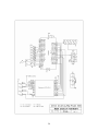
4.2 Base station hardware
Base station is responsible for receiving collected data, manipulating received
data into percentage format and sending to a computer through a serial communication
(RS232) for a graphical analysis. It consists three major parts which are microcontroller,
radio packet controller and serial communication hardware.
Microcontroller
The connection of microcontrollers in both the base station’s hardware and
remote end’s hardware are nearly identical. The only differences between the two are the
USART and accelerometers. There is no accelerometer connected with base station’s
hardware since its purpose is used to receive and process data. For the USART, PD.1 is
used to transmit data serially to the serial communication hardware. Please refer to
section 4.1 for detail on microcontroller.
Radio Packet Controller
The connection of SP2 in both the base station’s hardware and the remote end’s
hardware are identical. Please refer to section 4.1 for detail on SP2.
Serial Communication
Serial communication (RS232) transmits data from microcontroller to computer’s
Hyper Terminal. The USART of base station has baud rate of 9600bps, one stop bits, no
parity bit and data frame is 8-bit.
The RS232 is negative logic which means that a ‘1’ is negative voltage and a ‘0’
is positive voltage. A converter is needed for TXD and RXD and Max233 is chosen
because of its internal capacitors. Max232 is a popular choice but four external
capacitors seem too much for the design and Max233 functions just as well as it.
11
A female DB9 connector is soldered with Max233 media driver. Pin 5 (T1Out) of
Max233 is connected with pin 2 (Receive data) of DB9. Pin 5 (Signal ground) of DB9
connector is connected with ground bus of prototype board. Then, a serial cable is
connected with both DB9 connector and computer together. Since USART protocol is
used for the serial communication, PD1 of microcontroller which is TXD is connected
with pin 2 of Max233. RXD of microcontroller is not necessary in this project since the
data always goes into one direction to computer.
There was a problem encountered when soldering the DB9 connector onto the
prototype board. Its pin would not fit in either 0.1” grid board or the 2mm grid board.
However, with help from Dr. Land, it is fitted onto the board by drilling bigger holes.
12
4.3 Embedded program
There are two embedded application in the system. The program at the remote
end’s microcontroller is responsible to collect data from accelerometers and to send the
data in packet through a radio packet controller. The program at the base station’s
microcontroller is responsible to receive data through radio packet controller and to
process packet into a meaningful data format. Then, reorganized packet is sent through a
USART to a computer for graphical analysis.
Here, the remote end’s program is explained in detail.
•
interrupt [TIM0_OVF] void timer0_overflow(void)
Since the system is required to collect data in 10Hz, an interrupt service routine
(ISR) serves the best by providing an accurate time interval for operation.
Timer/Counter 0 is chosen and ISR occurs every 100 millisecond. A 100
millisecond interval is chosen so that people normally would not notice
significant data delay. Moreover, a 50ms interval had been tested on the system
and it worked.
•
unsigned char read_ADC(unsigned char ADC_input)
This function is called by passing a value to read the accelerometer’s signals. The
value passed is a channel number such as ADC0, ADC1, or ADC2. The function
allows one ADC reading at a time. Although multiple ADC readings are allowed
with Mega32, it is safer and more accurate to read one channel at a time. This is
done by a flag called ADC_doneconversion which indicates if an ADC channel is
being read.
•
void Task1(unsigned char ADC_value)
This function is for debugging purpose. It tests whether the accelerometer’s
signals are correct and it is done by reading a converted value of one of the three
channels. The value read must be within a range from 0x60 to 0xA0 (explained in
section 4.1 Accelerometer). One channel at a time is tested.
13
•
void Task2(unsigned char ADC_v1, unsigned char ADC_v2)
This function is for debugging purpose. It is very similar to the Task1 function
above. However, instead of testing one channel’s value at a time, two channel’s
values are compared with the range from 0x60 and 0xA0. This function is used to
prove that microcontroller is reading multiple channels properly.
•
interrupt [EXT_INT0] void ext_int0(void) //detect TXA: MCU to SP2 transfer
The function is processed by an external interrupt 0 and it is used for the
microcontroller to acknowledge that SP2 is ready for the data transfer. Detail on
how it operates is explained below.
MCU to SP2 (Transmission)
Doing a byte transfer from the MCU to the SP2 is asynchronous and there are
couple procedures that should be handled before transmitting. First, if there is a valid
packet in SP2 waiting to be uploaded into MCU, data must be uploaded before
transmitting. Second, data lines must not be set to output until step 3. After the SP2 has
accepted the transfer request, data lines could stay as output until the entire packet is sent
out. Then, steps for transmitting data are as follow:
1. MCU is ready to transfer data. It asserts TXR’ from high to low to initiate a
transfer request.
2. MCU waits for SP2 to pull TXA’ low which means request is accepted.
3. MCU set data lines to output and place the lower 4-bit on the data lines.
4. MCU set TXR’ back to high to tell SP2 that data is present.
5. MCU waits for SP2 to set TXA’ back to high to acknowledge that data has been
read.
Then, the steps are done again for the higher 4-bit. Process will repeat until the entire
packet is read.
External interrupt 0 is used as TXA’. MCU needs to detect a falling or rising edge of
TXA’ and it works by setting register MCUCR[1:0] to 10 or 11 respectively. Also,
GICR.6 must be set to enable the external interrupt 0 requested.
14
Here, the base station’s program is explained in detail.
•
interrupt [TIM0_OVF] void timer0_overflow(void)
This has the same purpose of the timer/counter 0 interrupt that is explained above.
•
void Repack_Sendmsg(void)
This function serves two purposes. First, packet received by the base station’s
microcontroller is in digital count. Here, the packet is converted into percentage
of the acceleration and the range is from -100% to +100%. This conversion could
actually be done by the remote end’s microcontroller. However, in order to
minimize the amount of data transmission through the radio packet controllers,
the conversion is done at the base station to maintain data integrity.
Second, the function calls built-in function printf to send data through USART.
Using printf function saves a lot of time on writing codes for the USART.
Although the compiler generates a significant amount of assembler codes by
handling printf, it only generates a few codes after calling it the first time. So,
considering the pros and cons of using printf, I chose to implement it to ease the
programming effort.
•
interrupt [EXT_INT1] void ext_int1(void) //detect RXR: SP2 to MCU transfer
The function is processed by an external interrupt 1 and it is used for the
microcontroller to know that SP2 is ready for data upload. Detail on how it
operates is explained below.
15
SP2 to MCU (Receiving)
Doing a byte transfer from the SP2 to the MCU is asynchronous and steps are
shown below:
1. SP2 asserts RXR’ low to initiate a transfer request.
2. MCU pulls RXA’ low to tell SP2 that request is accepted.
3. SP2 places data on the data lines and sets RXR’ back to high to tell MCU that
data is present.
4. MCU reads the data from data lines and set RXA’ back to high to acknowledge
that data has been read.
Then, the steps are done again for the higher 4-bit. Process will repeat until the entire
packet is read. Notice that data lines should be set as input before initiate a transfer
request. They will only be set as output during a transmitting operation.
External interrupt 1 is used as RXR’. MCU needs to detect a falling or rising
edge of RXR’ and it works by setting register MCUCR[3:2] to 10 or 11 respectively.
Also, GICR.7 must be set to enable the external interrupt 1 requested.
16
4.4 Matlab application
Matlab is chosen to analysis data in graphical interpretation because of its
powerful mathematical and graphical tools. Through the serial communication, a matrix
with three columns is displayed on Hyper Terminal. Data received on Hyper Terminal is
saved into a text file on a directory.
The matrix’s column is separated with a space and Matlab can easily load the text
file into workspace. Once data loaded, a matrix variable called data_percent is created.
Then, data_percent is processed and converted into a new matrix with unit g. The new
matrix is saved into variable named data_g. The range of data_g should be from +2g to 2g.
Each column of data_g is saved into a new variable representing its specific axis.
Five graphs are plotted and first three graphs show X-axis, Y-axis and Z-axis data
respectively. Fourth graph shows all three axes and fifth graph shows the scalar quantity
of all three axes. Axis labels and titles are shown on each graph and each axis has a
unique color representing itself. Since this project is designed to be simple and userfriendly. A color images of the graphs are saved automatically as xaxis.jpg, yaxis,jpg,
zaxis,jpg, result.jpg, scalarquan.jpg in the same folder of the Matlab command file.
17
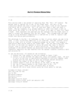
5) Test Results
Demonstration has been given to Dr. Land at a teaching lab in Corson Hall. The
system functions well and data collected are good. The design has been proved to be
successful. During demonstration, the system was tested with a range of 20 plus meters
and the base station can receive data without any difficulty. The specification of radio
packet controller claims to be 50 meters range in building. Because of this impressive
range, the project can be greatly applied into future application or design.
The accelerometers are suitable for the designed application. From various tests,
a person can hardly reach an acceleration of 2g although a 2g motion is possible with
vigorous movements. Z-axis of the system is positive pointing upward and negative
pointing downward. Gravitational force on earth is -1g and the tested value of Z-axis
while being idle is proved to be consistent with this theoretical value. Notice that both X
and Y axes have value of 0g when they are idle but Z-axis has value of -1g when it is idle.
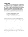
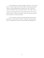
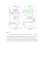
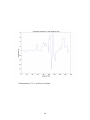
Two samples of test results are documented in this report. The first test result is
shown below and the Matlab code is modified a little to combine four graphs into a figure.
This is because a more understandable illustration can be done in a combine figure.
Second test result is shown in Appendix F and five graphs including scalar quantity are
shown.
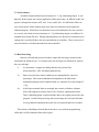
Test 1:
At the first test, the accelerometer device was moved in a circular motion along
XY plane. Sine waves were generated on X-axis and Y-axis. Z-axis was supposed to be
constant at a value of -1g. However, this test was done by a human being and the interval
between each circular motion varied. It is very difficult to finish each circle with same
period of time and same speed. As a result, irregular sine waves were generated on Xaxis and Y-axis and Z-axis also had values varying around -1g. A figure of the test is
shown on next page.
18
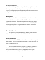
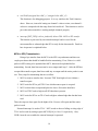
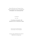
Test 2:
At this test, all three axes were tested at a different period of time. One axis was
tested along its positive and negative axis while the other two axes were kept still. X-axis
was tested from 8th second to 10th second. Z-axis was tested from 10th second to 12th
second. Finally Y-axis was tested from 14th second to 16th second. Figures of X-axis, Yaxis, Z-axis, combined axes and scalar quantity of combined axes are shown in Appendix
F.
19
6) Conclusion
This project has fulfilled my desire to build a system based on microcontroller. I
have been able to apply my electrical and computer engineering background to finish the
task. The project was based on heavy research and planning. Any alternative solutions
had been considered carefully. The system is kept compact throughout the
implementation and layout of prototype board was carefully designed. During the project,
I did not encounter any major problems and developing the system went well. Overall, I
enjoyed working on this project. I have trained myself to be good at soldering parts even
with surface mount capacitors. I have learned to be patient when debugging hardware
and software. Most important is that I know how to make decision when there are
alternative solutions pointing into same or different directions.
There are many additions which could be made to the basic system I built. If
there were more manpower, this project could be expanded greatly and more interesting
features could be added into the system. Instead of just getting acceleration on three axes,
it could also keep track on how the device has moved. Also, a smaller board could be
built specially for the remote end’s hardware. Although the final remote end’s hardware
is not bulky, the device would fit into more applicable place if it was smaller. It could
truly be used in a grade school’s science class if hardware is properly placed into an
enclosure.
20
7) Acknowledgements
This project would not be done without Dr. Bruce Land’s support and guidance.
I would like to thank him for soldering the tiny accelerometers on to the prototype boards.
And I owe him an apology for hurting his finger when drilling a hole on the board.
I also would like to thank my family and girlfriend for supporting me. I have
gained a lot of encouragement from them during my studies. They have been well
supporting and respecting my decision on the Mastering of Engineering studies at Cornell
University.
21
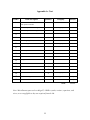
Appendix A: Cost
Item #
1
Item description
Quantity
Company
Price($)
2
Lemos International
198
Radiometrix SP2-433-160
radio packet controller
2
Solderable perf board 2mm grid
1
Digikey
15.93
3
Solderable perf board 0.1” grid
2
All electronics
4
4
Breadboard
2
All electronics
10
5
Pushbuttons
4
All electronics
1
6
5V Voltage regulator (LM78M05)
2
All electronics
1
7
4.55V Voltage detector (TL7757)
2
Digikey
1.44
8
40 pin socket
2
Jameco electronics
2.6
9
9V Battery holder
2
Jameco electronics
1.58
10
Green LED
10
Jameco electronics
1.2
11
Red LED
10
Jameco electronics
1.7
12
Orange LED
2
Jameco electronics
0.98
13
Yellow LED
2
Jameco electronics
0.52
14
D-sub female connector
1
Jameco electronics
0.6
15
9V alkaline battery
2
Jameco electronics
5.18
16
Antenna 433MHz
2
Digikey
6.9
17
ADSL311 +/- 2g accelerometer
2
Analog Devices
Sample
18
MAX233 media driver
1
Maxim-IC
Sample
Total:
252.63
Note: Miscellaneous parts such as Mega32, 16MHz crystals, resistor, capacitors, and
wires, etc are negligible as they are acquired from the lab.
22
Appendix B: Schematics
23
24
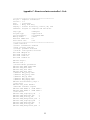
Appendix C: Remote end microcontroller’s Code
/*********************************************
Project : Complete Transmitter
Version : 1.2
Date
: 12/05/2003
Author : Wong, Kim Fung
Company : Cornell University, Ithaca, NY, USA
Comments: Program is complete and functions.
Chip type
: ATmega32
Program type
: Application
Clock frequency
: 16.000000 MHz
Memory model
: Small
External SRAM size : 0
Data Stack size
: 512
*********************************************/
//LEDs indicator
//Green: transmitter enabled
//Red: receiver enabled
//Orange: preamble detected
//Yellow: valid packet received
#include <Mega32.h>
#include <string.h>
#include <stdio.h>
#include <stdlib.h>
#define begin {
#define end }
//Accelerometer parameters
#define ADC_VREF_TYPE 0x00
#define ADC_Xsel 0x00
#define ADC_Ysel 0x01
#define ADC_Zsel 0x02
//#define ADC_pos2g 0xA0
//#define ADC_pos1g 0x90
//#define ADC_0g 0x80
//#define ADC_neg1g 0x70
//#define ADC_neg2g 0x60
#define Accelerometer_range 2
//SP2 reset
#define SP2_reset PORTD.7
//MCU-SP2 transfer signals
#define TXR PORTC.6 //TXA PIND.2
#define RXA PORTC.5 //RXR PIND.3
//SP2 states
#define TXA_reqaccept_lsb
1
#define TXA_dataread_lsb
2
#define RXR_tranreq_lsb
3
#define RXR_datapresent_lsb 4
#define TXA_reqaccept_msb
5
#define TXA_dataread_msb
6
#define RXR_tranreq_msb
7
#define RXR_datapresent_msb 8
25
//Global variables
//Accelerometer variables
unsigned char ADC_X;
unsigned char ADC_Y;
unsigned char ADC_Z;
unsigned char ADC_doneconversion;
//Control byte for SP2 transmitter
unsigned char TX_control_byte;
//Counter for transmitting bytes
unsigned char TX_byte_count;
//Position for transmitting bytes
unsigned char TX_byte_pos;
//Buffer for data packet
unsigned char MCU_to_SP2_buffer[10];
//Control byte for SP2 receiver
unsigned char RX_control_byte;
//Counter for receiving bytes
unsigned char RX_byte_count;
//Position for receiving bytes
//unsigned char RX_byte_pos;
//Buffer for data packet - junk
unsigned char SP2_to_MCU_buffer[2];
//flag for getting Control byte
bit Getting_control_byte;
unsigned char TX_state;
unsigned char RX_state;
//interrupt variables
unsigned char reload;
unsigned int time0;
void initialize(void)
begin
//ADC input(X,Y,Z axes)
//PA0=X, PA1=Y, PA2=Z
DDRA=0xF8;
//testing
DDRB=0xFF;
PORTB=0xFF;
//MCU to SP2 interface
//Bit6:TXR Bit5:RXA
DDRC=0xF0;
PORTC=0xF0;
//Bit2:TXA
DDRD=0xF3;
Bit3:RXR
Bit7:SP2_reset
// Timer/Counter 0 initialization
// Clock source: System Clock
time0=0;
reload=256-250;
TCCR0=0x03; //clk/64
26
TCNT0=reload;
//Timer/Counter0 Overflow Interrupt Enable
TIMSK=0x01;
//ADC initialization
ADMUX=ADC_VREF_TYPE|0x20;//Left adjust result
ADCSR=0x87;
ADC_doneconversion=1;
//SP2 initialization
SP2_reset=0;
TXR=1; //PORTC.6-out
RXA=1; //PORTC.5-out
TX_control_byte=0x04;
RX_byte_count=0;
//RX_byte_pos=0;
Getting_control_byte=1;
TX_state=1;
RX_state=3;
GICR=0xC0; //External interrupts 0,1 enabled
MCUCR=0x0A; //Falling edge generates interrupt
// Global enable interrupts
#asm("sei")
end
// Timer 0 overflow interrupt service routine
interrupt [TIM0_OVF] void timer0_overflow(void)
begin
//reload to force 1ms overflow
TCNT0=reload;
++time0;
end
// Read the AD conversion result
unsigned char read_ADC(unsigned char ADC_input)
begin
ADMUX=ADC_VREF_TYPE|0x20;
ADMUX|=ADC_input;
//Start the ADC conversion
//ADSC(bit6) returns to zero after conversion
ADCSR|=0x40; //ADCSR=0xc7
//Wait for the ADC conversion to complete
while ((ADCSR & 0x10)==0);
ADCSR|=0x10;
ADC_doneconversion=1;
return ADCH;
end
27
/*
//Testing: show one axis working alone
void Task1(unsigned char ADC_value)
begin
if (ADC_value<=0xA2 && ADC_value>=0x92)
else if (ADC_value<0x92 && ADC_value>0x82)
else if (ADC_value==0x82)
else if (ADC_value<0x82 && ADC_value>0x72)
else if (ADC_value<=0x72 && ADC_value>=0x62)
else PORTB=~0xff;
PORTB=~0x0f;
PORTB=~0x55;
PORTB=~0x00;
PORTB=~0xaa;
PORTB=~0xf0;
end
*/
//Testing: show two axes working together
void Task2(unsigned char ADC_v1, unsigned char ADC_v2)
begin
unsigned char LED,LED_X,LED_Y;
if (ADC_v1<=0xA2 && ADC_v1>=0x92)
else if (ADC_v1<0x92 && ADC_v1>0x82)
else if (ADC_v1<0x82 && ADC_v1>0x72)
else if (ADC_v1<=0x72 && ADC_v1>=0x62)
else if (ADC_v1==0x82)
LED_X=0b11000000;
LED_X=0b10000000;
LED_X=0b01000000;
LED_X=0b00000000;
LED_X=0b11000001;
if (ADC_v2<=0x9D && ADC_v2>=0x8D)
else if (ADC_v2<0x8D && ADC_v2>0x7D)
else if (ADC_v2<0x7D && ADC_v2>0x6D)
else if (ADC_v2<=0x6D && ADC_v2>=0x5D)
else if (ADC_v2==0x7D)
LED=LED_X|LED_Y;
PORTB=~LED;
LED_Y=0b00110000;
LED_Y=0b00100000;
LED_Y=0b00010000;
LED_Y=0b00000000;
LED_Y=0b00110010;
end
//detect TXA: MCU to SP2 transfer
interrupt [EXT_INT0] void ext_int0(void)
begin
unsigned char temp_TX_data;
//PORTB=~0xF0; //debugging!
switch (TX_state)
{
case (TXA_reqaccept_lsb):
begin
//PORTB=~0x10; //debugging!
//set data lines to output & place data on the data lines
DDRC=DDRC | 0x0F;
PORTC=(PORTC&0xF0)|(MCU_to_SP2_buffer[TX_byte_pos] & 0x0F);
TXR=1; //tell SP2 that data is present
MCUCR=0x03; //rising edge for data read
TX_state=TXA_dataread_lsb; //Next state
end
break;
28
case (TXA_dataread_lsb):
begin
//PORTB=~0x20; //debugging!
//wait for SP2 to set TXA to high to tell
//MCU that data has been read
TXR=0; //transfer request by MCU
MCUCR=0x02; //falling edge for request accept
TX_state=TXA_reqaccept_msb;
end
break;
case (TXA_reqaccept_msb):
begin
//PORTB=~0x40; //debugging!
//shift the MS nibble to LS and send to data lines
temp_TX_data=(MCU_to_SP2_buffer[TX_byte_pos] &0xF0)>>4;
PORTC=(PORTC & 0xF0)| temp_TX_data;
TX_byte_pos++;//increment transmit buffer position
TXR=1; //data present
MCUCR=0x03; //rising edge for data read
TX_state=TXA_dataread_msb;
end
break;
case (TXA_dataread_msb):
begin
//PORTB=~0x80; //debugging!
if (TX_byte_pos < TX_byte_count)
{
TXR=0;//transfer request
MCUCR=0x02; //falling edge for request accept
}
else
{
DDRC=0xF0; //done TX, set data lines to input
MCUCR=0x0A; //enable EXT_INT1 on falling edge
}
TX_state=TXA_reqaccept_lsb;
end
break;
}
end
//detect RXR: SP2 to MCU transfer
interrupt [EXT_INT1] void ext_int1(void)
begin
switch (RX_state)
{
case (RXR_tranreq_lsb):
begin
//PORTB=~0x01; //debugging!
RXA=0; //Step2:MCU pulls RX accept low
29
MCUCR=0x0C; //rising edge for data present
RX_state=RXR_datapresent_lsb; //Next state
end
break;
case (RXR_datapresent_lsb):
begin
//PORTB=~0x02; //debugging!
//SP2 turns on bus drivers, places LS nibble
//onto data lines and set RX request to high
SP2_to_MCU_buffer[0]=PINC & 0x0F;
RXA=1; //data read
MCUCR=0x08;//falling edge for transfer request
RX_state=RXR_tranreq_msb;
end
break;
case (RXR_tranreq_msb):
begin
//PORTB=~0x04; //debugging!
RXA=0; //request accept by MCU
MCUCR=0x0C; //rising edge for data read
RX_state=RXR_datapresent_msb;
end
break;
case (RXR_datapresent_msb):
begin
//PORTB=~0x08; //debugging!
//shift the MS nibble to lower, read data lines
SP2_to_MCU_buffer[0]=(PINC<<4)|SP2_to_MCU_buffer[0];
MCUCR=0x08; //falling edge for transfer request
if (Getting_control_byte)
{
Getting_control_byte=0;
RX_control_byte=SP2_to_MCU_buffer[0];
RX_byte_count=SP2_to_MCU_buffer[0] & 0x3F;
}
else if (RX_byte_count > 0) RX_byte_count--;
if ((Getting_control_byte==0)&&(RX_byte_count==0))
{
Getting_control_byte=1;
MCUCR=MCUCR | 0x02;
}
RXA=1;
RX_state=RXR_tranreq_lsb;
end
break;
}
end
30
void main(void)
begin
initialize();
while (1)
{
if (time0==10)
SP2_reset=1; //SP2 ready
if (time0==100)
begin
time0=0; //reset timer
//X-axis
if (ADC_doneconversion==1)
{
ADC_doneconversion=0;
ADC_X=read_ADC(ADC_Xsel);
}
//Y-axis
if (ADC_doneconversion==1)
{
ADC_doneconversion=0;
ADC_Y=read_ADC(ADC_Ysel);
}
//Z-axis
if (ADC_doneconversion==1)
{
ADC_doneconversion=0;
ADC_Z=read_ADC(ADC_Zsel);
}
//Task2(ADC_X,ADC_Y);
TX_byte_count=0;
TX_byte_pos=0;
MCU_to_SP2_buffer[0]=TX_control_byte;
TX_byte_count++;
while (TX_byte_count < 4)
{
//testing: hardcode sequence of data
//MCU_to_SP2_buffer[TX_byte_count]=0x55;
//if (TX_byte_count==1)
MCU_to_SP2_buffer[TX_byte_count]=0x70;
//else if (TX_byte_count==2)
MCU_to_SP2_buffer[TX_byte_count]=0x75;
//else if (TX_byte_count==3)
MCU_to_SP2_buffer[TX_byte_count]=0x78;
if (TX_byte_count==1)
MCU_to_SP2_buffer[TX_byte_count]=ADC_X;
else if (TX_byte_count==2)
MCU_to_SP2_buffer[TX_byte_count]=ADC_Y;
else if (TX_byte_count==3)
MCU_to_SP2_buffer[TX_byte_count]=ADC_Z;
31
//Show Y-axis on remote end's hardware
PORTB=~ADC_Y;
TX_byte_count++;
}
//assert TXR low to initiate transfer to SP2
//& make sure RXA is high
TXR=0;
MCUCR=0x0A; //falling edge for request accept
end
}
end
32
Appendix D: Base station microcontroller’s Code
/*********************************************
Project : Complete Receiver
Version : 1.2
Date
: 12/06/2003
Author : Wong, Kim Fung
Company : Cornell University
Comments: Program is complete and functions.
Chip type
: ATmega32
Program type
: Application
Clock frequency
: 16.000000 MHz
Memory model
: Small
Internal SRAM size : 2048
External SRAM size : 0
Data Stack size
: 512
*********************************************/
//LEDs indicator
//Green: transmitter enabled
//Red: receiver enabled
//Orange: preamble detected
//Yellow: valid packet received
#include <Mega32.h>
#include <string.h>
#include <stdio.h>
#include <stdlib.h>
#define begin {
#define end }
//difference of 2g & 0g in digital count
#define ADC_diff 0x20
//SP2 reset
#define SP2_reset PORTD.7
//MCU-SP2 transfer signals
#define TXR PORTC.6 //TXA PIND.2
#define RXA PORTC.5 //RXR PIND.3
//SP2 states
#define TXA_reqaccept_lsb
1
#define TXA_dataread_lsb
2
#define RXR_tranreq_lsb
3
#define RXR_datapresent_lsb 4
#define TXA_reqaccept_msb
5
#define TXA_dataread_msb
6
#define RXR_tranreq_msb
7
#define RXR_datapresent_msb 8
//Global variables
//Control byte for SP2 receiver
unsigned char RX_control_byte;
//Counter for receiving bytes
unsigned char RX_byte_count;
//Position for receiving bytes
unsigned char RX_byte_pos;
33
//Buffer for data packet
unsigned char SP2_to_MCU_buffer[4];
//flag for getting Control byte
bit Getting_control_byte;
//unsigned char TX_state;
unsigned char RX_state;
//for TXC interrupt
unsigned char RS_head;
unsigned char RS_tail;
//buffer for reorganized packet to PC
int RS_buffer[6];
//interrupt variables
unsigned char reload;
unsigned int time0;
void initialize(void)
begin
//testing
DDRB=0xFF;
PORTB=0xFF;
//MCU to SP2 interface
//Bit6:TXR Bit5:RXA
DDRC=0xF0;
PORTC=0xF0;
//Bit0:RXD
//Bit2:TXA
DDRD=0xF3;
Bit1:TXD
Bit3:RXR Bit7:SP2_reset
//try bit0 as output?????
//Timer/Counter 0 initialization
time0=0;
reload=256-250;
TCCR0=0x03; //clk/64
TCNT0=reload;
//Timer/Counter0 Overflow Interrupt Enable
TIMSK=0x01;
//USART initialization
UCSRA=0x00;
UCSRB=0x08; //transmitter enable
UCSRC=0x86; //8bit data
UBRRL=0x67; //9600 baud rate
UBRRH=0x00;
//SP2 initialization
SP2_reset=0;
TXR=1; //PORTC.6-out
RXA=1; //PORTC.5-out
//TX_control_byte=0x04;
//TX_byte_count=0;
//TX_byte_pos=0;
RX_control_byte=0;
34
RX_byte_count=0;
RX_byte_pos=0;
Getting_control_byte=1;
//RX_done_flag=0;
//TX_state=1;
RX_state=3;
RS_head=0;
RS_tail=4;
GICR=0xC0; //External interrupts 0,1 enabled
MCUCR=0x0A; //Falling edge generates interrupt
// Global enable interrupts
#asm("sei")
end
// Timer 0 overflow interrupt service routine
interrupt [TIM0_OVF] void timer0_overflow(void)
begin
//reload to force 1ms overflow
TCNT0=reload;
++time0;
end
//Repacketize received data into percentrage of 2g
//and then print the new buffer(in %) to PC
void Repack_Sendmsg(void)
begin
int temp_value;
RS_head=0;
RS_tail=4;
//PORTB=~0x70;
//reorganized the SP2 packet into another buffer
//this is for user readability on the hyperterminal
RS_buffer[RS_head++]=SP2_to_MCU_buffer[0];
while (RS_head < RS_tail)
{
if (RS_head==1)
temp_value=((int)SP2_to_MCU_buffer[RS_head] - 130)*100;
else if (RS_head==2)
temp_value=((int)SP2_to_MCU_buffer[RS_head] - 125)*100;
else if (RS_head==3)
temp_value=((int)SP2_to_MCU_buffer[RS_head] - 133)*100;
RS_buffer[RS_head]=temp_value / 32;
printf("%4d",RS_buffer[RS_head]);
printf(" ");
RS_head++;
}
printf("\n\r");
RS_head=0;
end
35
//detect RXR: SP2 to MCU transfer
interrupt [EXT_INT1] void ext_int1(void)
begin
unsigned char temp_RX_data;
switch (RX_state)
{
case (RXR_tranreq_lsb):
begin
//PORTB=~0x01;
RXA=0; //Step2:MCU pulls RX accept low
MCUCR=0x0C; //rising edge for data present
RX_state=RXR_datapresent_lsb; //Next state
end
break;
case (RXR_datapresent_lsb):
begin
//PORTB=~0x02;
//SP2 turns on bus drivers, places LS nibble
//onto data lines and set RX request to high
SP2_to_MCU_buffer[RX_byte_pos]=PINC & 0x0F;
RXA=1; //data read
MCUCR=0x08;//falling edge for transfer request
RX_state=RXR_tranreq_msb;
end
break;
case (RXR_tranreq_msb):
begin
//PORTB=~0x04;
RXA=0; //request accept by MCU
MCUCR=0x0C; //rising edge for data read
RX_state=RXR_datapresent_msb;
end
break;
case (RXR_datapresent_msb):
begin
//PORTB=~0x08;
//shift the MS nibble to lower, read data lines
temp_RX_data = PINC;
SP2_to_MCU_buffer[RX_byte_pos]=(temp_RX_data<<4)
| SP2_to_MCU_buffer[RX_byte_pos];
RX_byte_pos++;
if (Getting_control_byte)
{
//get to know how many bytes the packet are
Getting_control_byte=0;
RX_control_byte=SP2_to_MCU_buffer[0];
//zero the bit6,7 to get the exact count
RX_byte_count=SP2_to_MCU_buffer[0] & 0x3F;
}
else if (RX_byte_count > 0) RX_byte_count--;
36
//done receiving a packet
if ((Getting_control_byte==0)&&(RX_byte_count==0))
{
Getting_control_byte=1;//done RX, enable
//if statements make sure the data are valid
//otherwise, data wouldn't be sent to USART
if ( (SP2_to_MCU_buffer[1] <= 0xA2)
&& (SP2_to_MCU_buffer[1] >= 0x62)
&& (SP2_to_MCU_buffer[2] <= 0x9D)
&& (SP2_to_MCU_buffer[2] >= 0x5D)
&& (SP2_to_MCU_buffer[3] <= 0xA5)
&& (SP2_to_MCU_buffer[3] >= 0x65))
//repacketize and dump data to PC
Repack_Sendmsg();
PORTB=~SP2_to_MCU_buffer[2];
}
MCUCR=0x08;//falling edge for transfer request
RXA=1;
RX_state=RXR_tranreq_lsb;
end
break;
}
end
void main(void)
begin
initialize();
while (1)
{
if (time0==10)
SP2_reset=1;
if (time0==500)
begin
time0=0; //reset timer
RX_byte_count=0;
RX_byte_pos=0;
UCSRB=0x08; //transmitter enable
MCUCR=0x08; //falling edge for request accept
end
}
end
37
Appendix E: Matlab Code
%Version: 1
%Date: December 1,2003
%This matlab file is used to display the data collected
%by the acceleration reading device
data_percent = load('result.txt')
data_g = data_percent*(2/100)
[row_size,col_size] = size(data_percent)
X=data_g(1:end,1)' %put 1st column of data_g in X
Y=data_g(1:end,2)' %put 2nd column of data_g in Y
Z=data_g(1:end,3)' %put 3rd column of data_g in Z
%calculating total scalar quantity of 3 axes
for i = 1:row_size
scalar_quan(i) = sqrt(X(i).^2 + Y(i).^2 + Z(i).^2)
end
t = 1:row_size;
%subplot(2,2,1);
plot(t,X,'bo--')
grid on;
title('Acceleration - Xaxis')
xlabel('samples (10Hz)')
ylabel('acceleration (g)')
%Automatically save the figure into the current
%work directory as xaxis.jpg with best resuoltion
print -djpeg100 xaxis.jpg
figure;
%subplot(2,2,2);
plot(t,Y,'gp-')
grid on;
title('Acceleration - Yaxis')
xlabel('samples (10Hz)')
ylabel('acceleration (g)')
print -djpeg100 yaxis.jpg
figure;
%subplot(2,2,3);
plot(t,Z,'r*:')
grid on;
title('Acceleration - Zaxis')
xlabel('samples (10Hz)')
38
ylabel('acceleration (g)')
print -djpeg100 zaxis.jpg
figure;
%subplot(2,2,4);
plot(data_g)
legend('X-axis','Y-axis','Z-axis')
title('Acceleration measurement - 3axes')
xlabel('samples (10Hz)')
ylabel('acceleration (g)')
print -djpeg100 result.jpg
figure;
plot(vector_quan)
title('Acceleration measurement - scalar quantity of 3axes')
xlabel('samples (10Hz)')
ylabel('acceleration (g)')
print -djpeg100 scalarquan.jpg
39
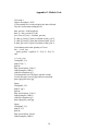
Appendix F: Matlab result
Test 2
A movement on X-axis was performed along positive and negative direction.
40
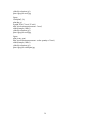
A movement on Y-axis was performed along positive and negative direction.
41
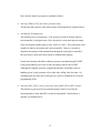
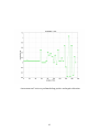
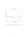
A movement on Z-axis was performed along positive and negative direction.
42
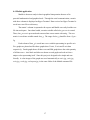
A figure including the X, Y and Z axes is shown.
43
Scalar quantity of X, Y, and Z axes is shown.
44
Appendix G: User’s Manual
System set up:
Ø Plug in a serial cable with base station’s DB9 connector and a computer.
Ø Make sure com1 is available for Hyper Terminal. If not, go to Device Manager of
Windows OS to change the com port.
Ø Open up a Hyper Terminal with 9600 baud rate, 1 stop bits, no parity and no flow
control. Connection’s name is up to user’s preference.
Ø Go to “File” on menu and “Properties” and select “Settings”. Click “ASCII
setup…”, choose “Append line feeds to incoming line ends” from “ASCII
Receiving”.
Ø Put 9V batteries into the base station’s and remote end’s battery holders. Make
sure the polarities are correct.
Data collecting:
Ø Make connection to the Hyper Terminal and go to “Transfer” and “Capture
Text…” on menu. Open the file named result.txt and make sure it is empty.
Ø Press “start” on the “Capture Text” window to start collecting data.
Ø When data is being collected, it is shown in three columns.
Ø When enough data are collected, click “stop” from Capture Text..” from
“Transfer”. Then, Hyper Terminal should be disconnected.
Data analysis:
Ø If matlabcommand.m is not yet available, copy it from the Appendix E above.
Ø Save result.txt and mathlabcommand.m on the same directory.
Ø Run the matlabcommand.m in Matlab and change the Matlab working directory
if necessary.
Ø A figure with the X-axis’s, Y-axis’s and Z-axis’s data is shown.
Ø Five image files called xaxis,jpg, yaxis,jpg, zaxis.jpg, result.jpg and
scalarquan.jpg are automatically saved into the same directory of the two other
files.
45
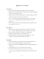
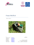
Appendix H: Picture
Remote end’s hardware
46
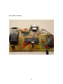
Base station’s hardware
47
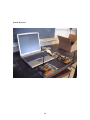
System Overview:
48
Appendix I: Bibliography
1. Mega32 datasheet
http://www.atmel.com/dyn/resources/prod_documents/doc2503.pdf
2. Radiometrix SP2-433-16 radio packet controller
http://www.radiometrix.co.uk/dsheets/sp2.pdf
3. Radiometrix SP2-433-16 radio packet controller evaluation kit
http://www.radiometrix.co.uk/dsheets/sp2ek.pdf
4. Mega32 prototype board
http://homepage.sunrise.ch/mysunrise/pfleury/avr-starterkit.html
5. Max233 driver/receiver
http://pdfserv.maxim-ic.com/en/ds/MAX220-MAX249.pdf
6. Analog Device ADXL311 +/-2g dual-axis accelerometer
http://www.analog.com/UploadedFiles/Data_Sheets/39398238692761ADXL311_a.pdf
7. National Instrument 5V voltage regulator (LM78M05)
http://www.national.com/ds/LM/LM341.pdf
8. CodeVision AVR evaluation download
http://www.hpinfotech.ro/html/download.htm
49