1
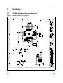
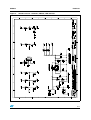
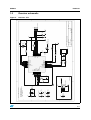
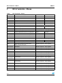
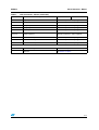
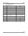
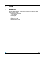
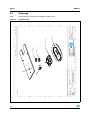
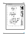
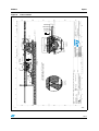
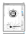
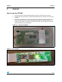
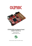
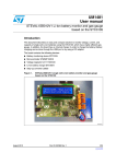
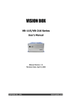
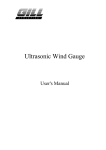
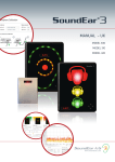
UM0273
User manual
VT5365 wireless reference design mouse with parallel battery
Introduction
This user manual, along with the VT5365 datasheet will enable you to evaluate the
STV-365-R03 single-chip wireless reference design mouse and assist you in the design of
your own VT5365 wireless mouse. If you have any questions, support can be obtained
through the normal regional sales/support groups.
Kit contents
April 2007
■
Reference design mouse, plus receiver
■
5 x VT5365V032 optical mouse sensor
■
3 x Lens/Aperture - see Section 3
■
5 x LED
■
USB cable/connector
Rev 2
1/17
www.st.com
Hardware
UM0273
1
Hardware
1.1
27MHz Wireless mouse schematics
Figure 1.
Wireless mouse - VT5365 sensor
2/17
UM0273
Wireless mouse - Switches, ZWheel, LED and PSU
$2I1072
Figure 2.
Hardware
3/17
Hardware
Figure 3.
4/17
UM0273
Wireless mouse - RF
D
C
B
A
C9
4.7uF
C11
100nF
GND
V33
GND
C14
100nF
SCL
GND
1
C18
100nF
V18_LNA
V18_ADC
C17
100nF
GND
GND
C16
100nF
V18_PLL
C15
100nF
V18_DIG
GND
V33
6
7
1
2
3
GND
GND
5
C1
22nF
56K/1%
R2
TP2
SDA
C6
220nF
R1
560
V33
V18_ADC
I2C EEPROM
M24C02RMN6
SDA
V33
SCL
WC
CE0
CE1
CE2
U2
C12
100nF
1. Resistance in Ohms, +/- 5%
2. All capacitors are 10V minimum.
3. Ceramic capacitor tolerance +/- 10%
4. NM = Not Mounted
1
2
3
4
5
6
7
8
9
10
2
PA2
PA3
RESET
TEST
V33_RF
V18_ADC
BIAS
VSS_RF
CPOUT
V18_LOOP_PLL
2
V18_DIG
V33
40
39
38
37
36
35
34
33
32
31
PA1
PA0
VSS_SUB_DIG
V18_DIG
VSS_OSC
OSC1
OSC2
V33_OSC
V33_DIG
V33_OUT
1
8
10nF
C7
10nF
C8
TP1
V18_PLL V18_LNA
C5
TBD
VDD
PB5
PA7
USBDM
USBDP
PB6
VSS_DIG
PA6
PA5
PA4
SDA
SCL
R5
330
100
C4
TBD
3
1K5/1%
R3
VDD
22pF
C3
Y1
12MHz
22pF
C2
GND
CONNECT
SW1
Date:
File:
A4
Size
Title
GND
VDD
GND
C13
100nF
C10
4.7uF
GND
4
4
Revision
A
USB CONNECTOR
1
2
3
4
J1
15/Mar/06
Sheet of
C:\temp\..\ST7WInD1x Dongle I2C EEPROM.Sch
Drawn By:
Number
ST7WIND11-DONGLE
GND
CONNECT / ACTIVITY INDICATOR
LED
LOOP ANTENNA
NM
Force USB mode
4
ST7WIND1X
30
29
28
27
26
25
24
23
22
21
U1
R6
3
D
C
B
A
Receiver - ST7
GND VCC
Figure 4.
4
Receiver schematic
V18_PLL
VSS_SUB_RF
RXNIN
RXPIN
V18_LNA
PB0
PB1
PB2
PB3
PB4
1.2
11
12
13
14
15
16
17
18
19
20
UNLESS OTHERWISE SPECIFIED:
UM0273
Hardware
5/17
Bill of materials - Mouse
UM0273
2
Bill of materials - Mouse
Table 1.
Bill of materials - Mouse
Ref.
Description
Manufacturer
Part Number
U1
Optical mouse sensor
STMicroelectronics
VT5365V032
U2
1K Byte EEPROM
STMicroelectronics
M24C01-WBN6P
U3
Step up converter L6920
STMicroelectronics
E-L6920D
Q2
BSS138 N-channel MOSFET, SOT23
Farnell
518-621
Q4
MMBT3904 NPN Transistor, SOT23
Farnell
742-960
D1
Low current 3mm red LED
Standard component - many suppliers
D2
5mm IR navigation LED
Agilent
D3
Single Diode (SMD) BAS 16
Standard component - many suppliers
X1
12MHz HC49/S Crystal
Standard component - many suppliers
L1
0.56uH Axial lead RF inductor T/H 10mm pitch
Farnell
512-448
L3
0.18uH Axial lead inductor T/H 10mm pitch
Farnell
512-345
L4
3.3uH Axial lead inductor T/H 10mm pitch
Farnell
513-404
L6
15uH Surface Mount Inductor DO1608 serie
Coilcraft
D01608C-15
SW1,SW2,SW3
Miniature microswitch, left, middle, right buttons
Standard component - many suppliers
SW4
Mechanical encoder (Zwheel)
ALPS
SW5
Sealed Keyswitch (SMD) B3S1000, ID button
Standard component - many supplier
SW6
Subminiature PCB mounted slide switch,
SPDT vertical 2.54mm pitch
Standard component - many suppliers
R6,R7,R8,R16
0R Resistor
Standard component - many suppliers
R28,R29
10R Resistor
Standard component - many suppliers
R15
33R Resistor
Standard component - many suppliers
R3
100R Resistor
Standard component - many suppliers
R1,R2
1K2 Resistor
Standard component - many suppliers
R10
47K Resistor
Standard component - many suppliers
R4,R12,R13,
R14,R19,R22
100K Resistor
Standard component - many suppliers
R36
220K Resistor
Standard component - many suppliers
R9,R17,R18,
R37
470K Resistor
Standard component - many suppliers
C36
15pF Capacitor
Standard component - many suppliers
C20,C32
22pF Capacitor
Standard component - many suppliers
C19
33pF Capacitor
Standard component - many suppliers
C12,C13
47pF Capacitor
Standard component - many suppliers
6/17
HSDL-4261
EC10E series
UM0273
Table 1.
Bill of materials - Mouse
Bill of materials - Mouse (continued)
Ref.
Description
Manufacturer
Part Number
C31
56pF Capacitor
Standard component - many suppliers
C27,C30
100pF Capacitor
Standard component - many suppliers
C37
180pF Capacitor
Standard component - many suppliers
C11
680pF Capacitor
Standard component - many suppliers
C23,C25
10nF Capacitor
Standard component - many suppliers
C1,C2,C9,C10,
C14,C15
100nF Capacitor
Standard component - many suppliers
C3
1uF Tantalum capacitor CASE B
Standard component - many suppliers
C4
10uF Tantalum capacitor CASE B
Standard component - many suppliers
C5,C8
47uF Tantalum capacitor CASE B
Standard component - many suppliers
Additional items not mounted on the PCB
Optics assembly
See Section 3: Optics
Aperture
See Section 3: Optics
7/17
Bill of materials - Mouse
UM0273
2.1
Bill of materials - Receiver
Table 2.
Bill of materials - Receiver
Reference
Description
Manufacturer
Part number
R1
560R Resistor (5%)
Standard component - many suppliers
R2
56K Resistor (1%)
Standard component - many suppliers
R3
1K5 Resistor (1%)
Standard component - many suppliers
R5
330R Resistor (5%)
Standard component - many suppliers
R6
100R Resistor (5%)
Standard component - many suppliers
C1
22nF Ceramic Capacitor (10%)
Standard component - many suppliers
C2,C3
22pF Ceramic Capacitor (5%)
Standard component - many suppliers
C4
47pF Ceramic Capacitor (5%)
Standard component - many suppliers
C6
220nF Ceramic Capacitor (10%)
Standard component - many suppliers
C7,C8
10nF Ceramic Capacitor (10%)
Standard component - many suppliers
C9,C10
4.7uF Ceramic Capacitor (10%)
Standard component - many suppliers
C1,C12,C13,
C14,C15,C16,
C17,C18
100nF Ceramic Capitor (10%)
Standard component - many suppliers
LD1
Green LED
Standard component - many suppliers
Y1
Quartz 12MHz 60ppm
Standard component - many suppliers
U1
ST7WinD11 Microcontroller
STMicroelectronics
U2
M24C02 EEPROM
STMicroelectroonics M24C02-RMN6
SW1
SMD Push Button
Standard component - many suppliers
J1
USB connector
Standard component - many suppliers
R4,C5
Not fitted
1. To order ST7 device, please contact STMicroelectronics.
8/17
ST7WIND11NSY(1)
UM0273
Optics
3
Optics
3.1
Manufacturers
STMicroelectronics has worked with optical component suppliers to produce a single piece
light guide with integrated lens. The kit contains 3 pieces. For more information please
contact the indivual supplier.
MaxEmil Photonics Corporation
7F, 135, Lane 235,
Bao Chiao Road,
Hsintien City,
Taipei, Taiwan
Tel: 886-2-89191179
Fax: 886-2-89191178
http://www.maxemil.com.tw
9/17
10/17
PCB
1
2
3
Date
6
Part No.
8
Date
Do Not Scale
Scale
Checked
7
Title
8
4 of 4
Sheet
Home, Personal Communication Sector- Imaging Division
STMicroelectronics
All dimensions
in mm
Mouse Base
Lens and Light Guide
ECN No.
F
E
D
C
B
A
Exploded view
Finish
Sig.
Aperture
7
Figure 5.
This drawing is the property of STMicroelectronics
and will not be copied or loaned without the
written permission of STMicroelectronics.
6
Sensor Package
Revision note
Drawn
Checked
Appd. Mech.
Appd. Elect.
Appd. Prod.
Appd. Q.A.
RevNo
Optics footprint in the base is available in IGES format
All dimensions in mm
5
Note:
Linear
0 Place Decimals 0
±1.0
1 Place Decimals 0.0 ±0.10
2 Place Decimals 0.00 ±0.07
Angular
±0.25 degrees
Diameter
+0.10/-0.00
Position
0.10
Surface Finish 1.6 microns
4
Drawings
F
LED
3
Tolerances, unless otherwise stated Interpret drawing per BS308, 3RD Angle Projection Material
2
3.2
E
D
C
B
A
Exploded View
1
Optics
UM0273
UM0273
Optics
Figure 6.
MaxEmil optics
11/17
Optics
UM0273
Figure 7.
12/17
MaxEmil aperture
F
E
D
C
B
2.20
Lens Set
3
PCB
1
Linear
0 Place Decimals 0
±1.0
1 Place Decimals 0.0 ±0.10
2 Place Decimals 0.00 ±0.07
Angular
±0.25 degrees
Diameter
+0.10/-0.00
Position
0.10
Surface Finish 1.6 microns
All dimensions in mm
3
This drawing is the property of STMicroelectronics
and will not be copied or loaned without the
written permission of STMicroelectronics.
2
SECTION J-J
SCALE 4 : 1
Finish
C
B
Aperture
OTQFP
Package
5
D
Sig.
16 °
Revision note
Drawn
Checked
Appd. Mech.
Appd. Elect.
Appd. Prod.
Appd. Q.A.
RevNo
Date
0.05
6
Part No.
DETAIL C
SCALE 8 : 1
9
7
8.60
0.05
0.60
6
1
ECN No.
1.02 ±0.14
8
Date
0.42 ±0.085
Checked
Do Not Scale
Scale
7
Title
8
Sheet
Home, Personal & Communication Sector- Imaging Division
STMicroelectronics
All dimensions
in mm
Datum A is the PCB Surface
A
Mouse Mat
LED
7
1.50 ±0.06
4
The distance from the LED lens surface
and the light pipe lens surface must
always be between 0.1 and 0.4mm
Mouse Base
DETAIL D
SCALE 8 : 1
7.50
Tolerances, unless otherwise stated Interpret drawing per BS308, 3RD Angle Projection Material
2
0.86 ±0.08
F
E
D
C
B
A
Figure 8.
A
1
UM0273
Optics
Cross section
13/17
F
E
D
C
B
L
42.75
E
Top View
16
1
Linear
0 Place Decimals 0
±1.0
1 Place Decimals 0.0 ±0.10
2 Place Decimals 0.00 ±0.07
Angular
±0.25 degrees
Diameter
+0.10/-0.00
Position
0.10
Surface Finish 1.6 microns
Tolerances, unless otherwise stated
1.40 Typ2
14/17
R
3.20
3
Keepout Area
All dimensions in mm
3
This drawing is the property of STMicroelectronics
and will not be copied or loaned without the
written permission of STMicroelectronics.
2
4
5
Finish
Material
DBS
6
0.2430
Top View
Revision note
190204
Drawn
Checked
Appd. Mech.
Appd. Elect.
Appd. Prod.
Appd. Q.A.
Sig.
Date
6
DETAIL E
SCALE 8 : 1
Part No.
Array centre verses package centre
RevNo
Sensor LED mounted on the underside of the PCB.
10
Interpret drawing per BS308, 3RD Angle Projection
9.80
4.90
Detail E
2
15
ECN No.
8
Date
Scale
Checked
7
Title
8
3 of 4
Sheet
Home, Personal & Communication Sector - Imaging Division
STMicroelectronics
Do Not Scale
Package Centre
Array Centre
All dimensions
in mm
7
F
E
D
C
B
A
Figure 9.
0.2150
A
1
Optics
UM0273
Sensor package
UM0273
4
General
General
How to use the VT5365
1.
Turn the mouse on using the sliding switch located on the bottom of the mouse.
2.
Connect the receiver to the PC via the USB cable/connector provided, the LED (LD1)
will light.
3.
Press the connect button on the receiver (SW1) and the LED will start to flash. It will
flash on/off for about 15 seconds, during this time press the connect button on the
bottom of the mouse. The mouse will now be connected, the LED will go off and only
light while data is being transmitted.
Figure 10. Connect and power
Figure 11. ST7 receiver
15/17
Revision history
5
UM0273
Revision history
Table 3.
16/17
Document revision history
Date
Revision
Changes
14-Mar-2007
1
Initial release published as a revision 0.3.
25-Apr-2007
2
No change in the document content.
Only corrected the document revision number.
UM0273
Please Read Carefully:
Information in this document is provided solely in connection with ST products. STMicroelectronics NV and its subsidiaries (“ST”) reserve the
right to make changes, corrections, modifications or improvements, to this document, and the products and services described herein at any
time, without notice.
All ST products are sold pursuant to ST’s terms and conditions of sale.
Purchasers are solely responsible for the choice, selection and use of the ST products and services described herein, and ST assumes no
liability whatsoever relating to the choice, selection or use of the ST products and services described herein.
No license, express or implied, by estoppel or otherwise, to any intellectual property rights is granted under this document. If any part of this
document refers to any third party products or services it shall not be deemed a license grant by ST for the use of such third party products
or services, or any intellectual property contained therein or considered as a warranty covering the use in any manner whatsoever of such
third party products or services or any intellectual property contained therein.
UNLESS OTHERWISE SET FORTH IN ST’S TERMS AND CONDITIONS OF SALE ST DISCLAIMS ANY EXPRESS OR IMPLIED
WARRANTY WITH RESPECT TO THE USE AND/OR SALE OF ST PRODUCTS INCLUDING WITHOUT LIMITATION IMPLIED
WARRANTIES OF MERCHANTABILITY, FITNESS FOR A PARTICULAR PURPOSE (AND THEIR EQUIVALENTS UNDER THE LAWS
OF ANY JURISDICTION), OR INFRINGEMENT OF ANY PATENT, COPYRIGHT OR OTHER INTELLECTUAL PROPERTY RIGHT.
UNLESS EXPRESSLY APPROVED IN WRITING BY AN AUTHORIZED ST REPRESENTATIVE, ST PRODUCTS ARE NOT
RECOMMENDED, AUTHORIZED OR WARRANTED FOR USE IN MILITARY, AIR CRAFT, SPACE, LIFE SAVING, OR LIFE SUSTAINING
APPLICATIONS, NOR IN PRODUCTS OR SYSTEMS WHERE FAILURE OR MALFUNCTION MAY RESULT IN PERSONAL INJURY,
DEATH, OR SEVERE PROPERTY OR ENVIRONMENTAL DAMAGE. ST PRODUCTS WHICH ARE NOT SPECIFIED AS "AUTOMOTIVE
GRADE" MAY ONLY BE USED IN AUTOMOTIVE APPLICATIONS AT USER’S OWN RISK.
Resale of ST products with provisions different from the statements and/or technical features set forth in this document shall immediately void
any warranty granted by ST for the ST product or service described herein and shall not create or extend in any manner whatsoever, any
liability of ST.
ST and the ST logo are trademarks or registered trademarks of ST in various countries.
Information in this document supersedes and replaces all information previously supplied.
The ST logo is a registered trademark of STMicroelectronics. All other names are the property of their respective owners.
© 2007 STMicroelectronics - All rights reserved
STMicroelectronics group of companies
Australia - Belgium - Brazil - Canada - China - Czech Republic - Finland - France - Germany - Hong Kong - India - Israel - Italy - Japan Malaysia - Malta - Morocco - Singapore - Spain - Sweden - Switzerland - United Kingdom - United States of America
www.st.com
17/17