1
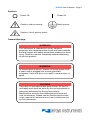
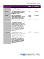
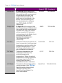
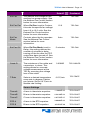
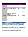
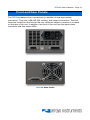
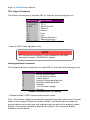
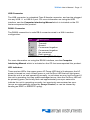
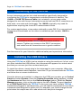
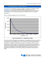
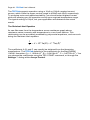
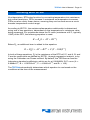
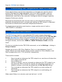
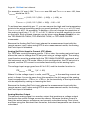
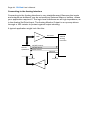
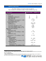
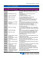
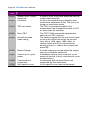
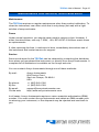
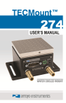
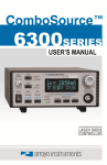
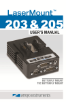
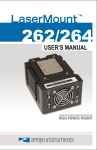
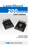
Page 2 · TECPak User’s Manual Table of Contents Introduction ............................................................................................................. 3 Safety Terms and Symbols ..................................................................................... 4 Quick Start ............................................................................................................... 6 Installation ............................................................................................................... 7 Operating Modes .................................................................................................... 9 Settings.................................................................................................................. 10 Arroyo Control ....................................................................................................... 14 Front and Rear Panels .......................................................................................... 15 Connecting to the TECPak ................................................................................... 18 Installing the USB Drivers ..................................................................................... 18 Working With Thermistors ..................................................................................... 19 Working With RTDs ............................................................................................... 21 User Calibration of Resistance Sensors ............................................................... 23 Controlling the Temperature Rate of Change ...................................................... 24 External Fan Control ............................................................................................. 24 Resistive Heaters and Heat/Cool Only Modes ..................................................... 25 Gain Control and the PID Loop............................................................................. 25 Using the AutoTune Function ............................................................................... 26 Compensating for Cable Resistance .................................................................... 27 Using the Analog Interface.................................................................................... 28 Specifications ........................................................................................................ 33 Error Messages ..................................................................................................... 35 Maintenance and Service, and Calibration ........................................................... 37 TECPak User’s Manual · Page 3 Introduction Thank you for choosing the TECPak from Arroyo Instruments. Your TECPak is a combination of leading edge technology combined with years of experience in the field of temperature control, and based on the proven designs found in the 5240 and 5300 Series TECSources. The TECPak was design for system integration applications, or simply where a user interface like that found on the 5300 Series TECSources is not required or desired. With high TEC power options, both RS232 and USB computer interfaces, analog interface, and small footprint, the TECPak will fit into almost any temperature control application. TECPak’s analog interface provides a way of both controlling and monitoring the state of the instrument, with analog temperature set point, actual temperature monitoring, stable indicator, and on/off control and status. This allows for control in applications that do not have a computer interface. The TECPak offers all the features you would expect from a modern temperature controller, including: Support for both thermistor and RTD sensors. 4-wire measurement mode for RTD sensors. AutoTune for automatic PID parameter calculation 0.004°C temperature stability 0.01°C resolution for both set point and actual temperatures 4A/8V and 5A/12V standard configurations, with custom configurations available What’s in the Box Along with the TECPak itself, a CD with electronic copies of this manual, the Computer Interfacing Manual, and USB drivers are included. For USA customers, a power cord is included. For non-USA customers, an IEC-60320C13 rated AC power cord must be provided. Accessories Arroyo Instruments also sells several accessories designed to work with the TECPak. These include: 1260B TECSource Cable, 5A, 2m This cable has DB-15 male/female connectors for interfacing to the LaserMount or other connectorized fixtures, and supports up to 5A of TE current and connections for the fan interface. A pigtailed version of Page 4 · TECPak User’s Manual this cable, with tinned ends for soldering into custom solutions, is available as p/n 1261B. 1262B TECSource Cable, 10A, 2m Similar to the 1260B cable, but adds wiring for 4-wire RTD sense, and therefore only needed for RTD applications. Also adds 10 Amp operating capability. A pigtailed version of this cable, with bare ends for soldering into custom solutions, is available as p/n 1263B. Pak Series Rack Mount Kit, 3 or 5 units (p/n 1402-RM) For installing your TECPak or LaserPak into a standard 19” rack. The kit accepts either 3 units for a 2U installation, or 5 units for a 3U installation. 10kΩ Thermistor (p/n 1600) Accurate to ±0.2°C. RS-232 NULL Cable, 3m (p/n 1200-NULL) USB Cable, 3m (p/n 1201) Safety Terms and Symbols The following safety-related terms are used in this manual: Warnings (noted by the WARNING heading) explain dangers that could result in physical injury or death; Cautions (noted by the CAUTION heading) explain conditions that could result in damage to the instrument, other equipment, or your device. Notes (noted by the NOTES heading) are not safety-related, and are intended simply to point out important information. If, at any time, any of the following conditions exist, or are suspected of existing, discontinue use of the unit until it can be inspected by qualified service personnel: Visible damage to the unit, including damage or stress caused during product shipment; Storage of the unit outside the standard storage temperature or humidity rating, or prolonged storage under harsh conditions; Failure to operate properly. If needed, contact your distributor or Arroyo Instruments for service or repair to ensure the safety of the product is maintained. TECPak User’s Manual · Page 5 Symbols Power Off Power On Caution, refer to manual Earth ground Caution, risk of electric shock General Warnings WARNING This instrument is intended for use by qualified personnel who understand the shock and laser hazards and are familiar with safety procedures required to avoid injury. Read this manual completely before attempting to use this product. WARNING To avoid electrical shock, ensure a 3-prong power cord is used, and is plugged into a earth-grounded receptacle. Failure to do so can result in severe injury or death. CAUTION There are no user-serviceable parts inside. All service and repair work shall be done by Arroyo Instruments or personnel authorized by Arroyo Instruments. Modifications done by non-authorized personnel will void the warranty. Please see the Service section later in this manual for instructions on how to obtain service for this instrument. Page 6 · TECPak User’s Manual Quick Start The TECPak was designed with ease of use in mind, and you will likely have little need for this manual for almost all of the features the unit offers. This section will show how you can quickly get the unit up and running in almost no time. The TECPak has a universal input power supply, accepting 90 to 240 VAC, and 50 or 60 Hz. This covers all conventional power worldwide, but ensure your AC power meets these requirements. Plug the AC cord into the unit and into the wall outlet. Turn on the power switch located on the IPC, and the unit will power up. The AC Power LED should light, and the On / Error LED should remain dark. Control of the TECPak can be done two ways: use the RS232 or USB computer interfaces and control the instrument from the PC, or use the analog interface. This quick start guide uses the computer interface. More information on the analog interface can be found later in the manual. Install the Arroyo Control software located on the CD that came with the instrument (it can also be downloaded from our web site), located in the Software folder on the CD. Once the software is installed, plug the instrument into your RS-232 or USB interface. For USB users, the instrument may also ask for drivers, which are also found on the CD. Launch Arroyo Control, and in the TECSource panel (if one is not visible, click Add Panel in the lower right of the window, and click Add a TEC Panel), select the communications port to which your TECPak is connected. For USB users, this will usually be the highest numbered port in the list. Click Connect, and Arroyo Control will begin controlling the TECPak. Once connected, you will be able to adjust settings, limits, and turn the output on or off. Next, connect the cable between your LaserMount or other fixture and the Output connector of the TECPak. We recommend using our cables as they have been designed to work well with the TECPak. If using your own cables, ensure they have been properly wired according to the pin-out of the TECPak and your fixture. Finally, set the set point to an appropriate temperature and turn the output on. You will see the voltage and current begin driving the fixture to the set point you have chosen. Depending on the thermal size of your fixture, it may take seconds or several minutes to reach the set point. If you notice the temperature is oscillating around the set point and not stabilizing, you may need to adjust the Gain setting in the Settings… dialog. TECPak User’s Manual · Page 7 You can use the AutoTune feature to automatically calculate the best PID values, or select from a set of eight factory preset values that typically cover most applications. To use the factory gains, if the temperature is quickly jumping up and down, the Gain will typically need to be reduced. If the temperature is slowly moving up and down, try a higher Gain. You may need to experiment with several gain settings to find the ideal value, and for even finer control, you can set the Gain to PID and directly set the PID control values. Installation Installation of the TECPak is very straightforward, as the quick start section above illustrated. This section will provide additional details and considerations for installing your TECPak. After unpacking the unit, make sure all packing materials have been removed and nothing obscures the ventilation ports on the front and back of the unit. The TECPak has a universal input power supply, accepting 90 to 240 VAC, and 50 or 60 Hz. This covers all conventional power worldwide, but ensure your AC power meets these requirements. CAUTION Do not exceed 250VAC on the line input. It is critical to maintain the proper voltage input into the unit. If the actual voltage exceeds 250VAC, damage to the unit may occur. Powering Up the Unit Connect the AC power cord to the unit. Turn the power switch, located on the AC power input power connector, into the on (|) position. The unit will go through a quick power-up self-test, and return to the last known operating state. The AC Power LED will light up, and the On / Error LED should remain dark until the TEC output is turned on (if Automatic Output On has been enabled, the On LED may light without user intervention). Page 8 · TECPak User’s Manual Ventilation The TECPak has vent holes on the front and rear of the unit. You must not block these vent holes, or overheating may occur, causing damage to the unit. CAUTION Do not operate the unit above +40°C ambient, and ensure the instrument is properly ventilated, or the unit may overheat and possible damage to the instrument may occur. Rack Mounting A rack mount kit (p/n 1402-RM) for standard 19” racks is available for the TECPak, and supports the rack mount of up to five units in either a 2U or 3U high opening, depending on the orientation of the TECPak. Because the units only ventilate from the front and rear, no air gapping is required above or below the units, and they can be rack mounted immediately above other equipment (no rack spacers required). Warm-up and Environmental Considerations In order to achieve the highest level of accuracy, the TECPak should be powered on for at least one hour prior to taking measurements. In addition, ensure that the unit is not operating outside the ambient temperature range or humidity conditions. TECPak User’s Manual · Page 9 Operating Modes Control Modes The TECPak offers three control modes: constant temperature mode (T Mode), constant resistance mode (R Mode), and constant current mode (Ite Mode). Changing the control mode can only be done through the computer interface, either through Arroyo Control, or by sending the appropriate TEC:MODE command. Constant temperature mode uses the sensor constants to calculate the resistance of the sensor at the desired or actual temperature. While most users will only need the temperature control mode, the constant resistance mode allows you to bypass the sensor equation and directly select the sensor set point. This can be useful when only the desired sensor value is known, or when the sensor-to-temperature conversion values are not available for your sensor. Using Limits The TECPak supports three different types of limits: temperature, sensor, and current. There is both a temperature high and temperature low limit, and if the actual temperature exceeds either of these limits, the output will be shut off. Likewise, both high and low limits exist for the sensor (R limits), and the output will be shut off if the sensor measurement exceeds either of these limits. It is important to properly set these limits to protect your device from damage. If you are uncertain on how to set the limits, please consult with your local distributor or directly with the factory. Page 10 · TECPak User’s Manual Settings All parameters of the TECPak can be viewed and changed over the computer interfaces. In addition, the set point can be changed via the analog interface, if it is enabled. Most parameters can be changed using a standard command, as defined in the Computer Interfacing Manual or through the Settings… dialog within Arroyo Control. Below is a list of the most common settings and the corresponding computer command to change it. Name Description Factory Default Computer Command Basic Settings Mode This set the operating mode (T Mode, R Mode, or Ite Mode) of the temperature controller. T Mode TEC:MODE Mount Specify the mount connected to the TECPak. If using a LaserMount, select the appropriate model. Otherwise, select User Defined. User Defined TEC:MOUNT I Lim I Lim sets the current limit of the temperature controller. The limit should be set to a value that is suitable for your Peltier device. 3A TEC:LIM:ITE Gain Gain controls the response of the temperature controller. A higher gain value will cause the controller to respond more quickly to the difference between the set point and the actual temperature, while a lower value will cause it to respond more slowly. Select PID for direct access to the PID parameters. Read more on setting gain below. 30 TEC:GAIN PID P The proportional term of the PID loop. Will only be available if Gain is set to PID. 1 TEC:P TECPak User’s Manual · Page 11 Name Description Factory Default 0.01 Computer Command PID I The integral term of the PID loop. Will only be available if Gain is set to PID. PID D The derivative term of the PID loop. Will only be available if Gain is set to PID. 0 TEC:D Sensor Sets the temperature measurement sensor. Can be Therm 100uA, Therm 10uA, Therm, RTD, or RTD (4-wire). Therm 100uA TEC:SENS T-Low Lim T-Low Lim is the lower temperature limit. If operating in T Mode and the actual temperature drops below this value, the output will be turned off. Temperature limits not monitored in R Mode or Ite Mode. Limit monitoring can also be disabled in software (see TEC:ENAB:OUTOFF command). -99°C TEC:LIM:TLO T-High Lim T-High Lim is the upper temperature limit. If operating in T Mode and the actual temperature rises above this value, the output will be turned off. Temperature limits not monitored in R Mode or Ite Mode. Limit monitoring can also be disabled in software (see TEC:ENAB:OUTOFF command). 125°C TEC:LIM:THI TEC:I Page 12 · TECPak User’s Manual Name Description Factory Default 0.01kΩ Computer Command TEC:LIM:RLO R-Low Lim R-Low Lim is the sensor low limit. If operating in R Mode and the actual sensor measurement drops below this value, the output will be turned off. R limits are not monitored in Ite Mode. Limit monitoring can also be disabled in software (see TEC:ENAB:OUTOFF command). R-High Lim R-High Lim is the sensor high limit. If operating in R Mode and the actual sensor measurement exceeds this value, the output will be turned off. R limits are not monitored in Ite Mode. Limit monitoring can also be disabled in software (see TEC:ENAB:OUTOFF command). 45kΩ TEC:LIM:RHI Tol Time Tolerance time is the amount of time, in seconds, that the actual temperature must be within the set point temperature +/- the Tol Temp value for the unit to be considered in tolerance. 5 seconds TEC:TOL Tol Temp Tolerance temperature is a temperature band (in °C) around the set point temperature. When the actual temperature is within this band for longer than the Tol Time setting, then the unit is considered to be in tolerance. 0.1°C TEC:TOL H/C Mode This selects the heating and/or cooling mode of the TECPak. See the section below titled “Resistive Heaters and Heat/Cool Only Modes” for more information. Heat/Cool TEC:HEATCOOL TECPak User’s Manual · Page 13 Name Description Factory Default Off Computer Command Ext Fan This selects the voltage for the auxiliary fan power supply. See the External Fan Control section below for more information. Ext Fan Pwr When Ext Fan is set to Custom, this sets the specific fan voltage from 4.0 to 12.0 volts. See the External Fan Control section below for more information. 12.0 TEC:FAN Ext Fan Mode Controls when the fan operates. See the External Fan Control section below for more information. Auto TEC:FAN Ext Fan Off When Ext Fan Mode is set to Delay, this setting defines the number of minutes to delay turning off the fan after the TEC output has been turned off. See the External Fan Control section below for more information. 5 minutes TEC:FAN Cable R The resistance of the cable and connectors, in ohms. This setting allows for accurate voltage measurement at the TEC by removing the voltage loss of the cable. 0.0080Ω TEC:CABLER T Rate Selects a desired temperature ramp rate in degrees Celsius per minute. Set to 0.0°C/min to disable rate limiting. 0.0°C/min TEC:TRATE TEC:FAN Sensor Settings ThermA A term in thermistor equation. 1.12924E-03 TEC:CONST ThermB B term in thermistor equation. 2.34108E-04 TEC:CONST ThermC C term in thermistor equation. 0.87755E-07 TEC:CONST RTD A A term in the RTD equation. 3.98480E-03 TEC:CONST RTD B B term in the RTD equation. -0.58700E-06 TEC:CONST Page 14 · TECPak User’s Manual Name Description Factory Default Computer Command RTD C C term in the RTD equation. 4.00000E-12 TEC:CONST RTD R0 R0 term in the RTD equation. 100.00 TEC:CONST Communications Settings Baud This sets the baud rate for the RS232 serial port. See the Computer Interfacing Manual which is included on the CD that accompanied this product. 9600 N/A, fixed at 9600 Err While Rmt To turn off the display of errors while in remote mode, set this value to “No”. To display errors while in remote mode, set this value to “Yes”. Yes REMERR Terminal Mode Terminal mode simply echoes any characters received over the serial or USB interfaces. No TERMINAL Msg Term This controls the output message termination, and can be set to CR/LF, CR, LF, or None. CR/LF TERM Arroyo Control While most of the settings of the TECPak can be changed over the computer interface using your own program (see the Computer Interfacing Manual for more detail), in many cases you simply want to operate the instrument from the PC like any other bench-top instrument. As mentioned earlier in this manual, Arroyo Control is a free software application that gives you 100% operating control of the TECPak, allowing you to change limits, settings, and set points, as well as monitor the operation of the instrument. From Arroyo Control, you can also enable the analog interface, and set the precision of the analog set point. You can install Arroyo Control from the CD or download it from our web site (go to the Software section). TECPak User’s Manual · Page 15 Front and Rear Panels The TECPak features four connections (in addition to the input power connector). They are: USB, RS-232, analog, and output connectors. The first three are located on the front of the unit, while the output connector is located on the rear of the unit. In addition, the front of the unit has the input power connector and two status LEDs. TECPak Front Panel TECPak Rear Panel Page 16 · TECPak User’s Manual TEC Output Connector The Output connection is a female DB-15, and has the following pin-out: DB-15 Pin Description 1, 2, & 9 TE (+) 3, 4, & 10 TE (-) 5&6 Earth Ground 7 Sensor+ 8 Sensor11 Fan+ 12 Fan – 14 Remote Sensor+* 15 Remote Sensor-* Output Connector (DB-15 Female) * Used in RTD 4-wire operation only. NOTE RTD and fan functionality is only available on TECPaks with serial number 130203819 or higher. Analog Interface Connector The Analog Interface connection is a male DB-15, and has the following pin-out: DB-15 Pin Description 1 On/Off Control Input 2 On/Off Status Output 3 Stable Output 4 Analog Temperature Monitor 5 Analog Temperature Set* 6 Ground 7 +5V Auxiliary Supply 8 Ground Output Connector (DB-15 Female) * Disabled when in RTD 4-wire measurement mode. The +5V auxiliary supply is provided for external low-power electronics. Current draw on this supply should not exceed 100mA. The Ground pin provides the ground reference for the logic and analog inputs as well as the auxiliary power supply. The analog interface is described in detail in the Using the Analog Interface section below. TECPak User’s Manual · Page 17 USB Connector The USB connector is a standard Type B female connector, and can be plugged into any USB 1.1 or USB 2.0 port. For more information on using the USB interface, see the Computer Interfacing Manual which is included on the CD that accompanied this product. RS232 Connector The RS232 connection is male DB-9 connector wired in a NULL modem configuration. Pin Description 2 Receive 3 Transmit 5 Ground 1,4,6 Commoned together 7,8 Commoned together 9 No connection Shell Earth ground RS232 Connector (DB-9 Male) For more information on using the RS232 interface, see the Computer Interfacing Manual which is included on the CD that accompanied this product. LED Indicators There are two LEDs: the upper green AC Power LED that is lit whenever the AC power is turned on; and a lower green or red On/Error LED that will light green when the unit is on and operating normally, or red when an error has occurred. If the unit is operating, but has unacknowledged errors, then the On/Error LED will be primarily green, but briefly flash red approximately once per second to indicate the unit is operating normally, but previously encountered an error (errors are automatically cleared by Arroyo Control, or can be cleared by sending an ERR? or ERRSTR? query). Page 18 · TECPak User’s Manual Connecting to the TECPak Arroyo Instruments carries two cable assemblies specifically designed for connecting the TECPak to temperature controlled fixtures or devices. The 1260B or 1262B TECSource Cable (not included) is a two meter cable, designed for use with Arroyo Instruments mounts and has DB-15 connectors on both ends, one male and one female. The 1262B is typically only used for applications requiring the 4-wire RTD measurement mode. For custom applications, a two-meter cable with a male DB-15 on one end and stripped and tinned leads on the other is available as part number 1261B or 1263B. NOTE Connections to the TECPak and the fixture must be secure. Tighten any screws on the DB-15 connectors, and make sure all connections are in good condition. See the manual for your fixture for additional safety and operational information. Installing the USB Drivers Using the TECPak via USB is just as simple as using the serial port. In fact, once you have installed the USB drivers, the instrument will appear as a virtual serial port that you can use just like a normal serial port. To install the drivers, simply plug in the instrument to your computer. When the Add New Hardware wizard appears, insert the CD you received with the TECPak and follow the on-screen instructions. Once the drivers are installed, to determine the COM port number, go to Control Panel and select System. Once the System Properties dialog appears, choose the Hardware tab then click on the Device Manager button. When the Device Manager appears, click on the plus sign to the left of Ports. The port identified as an USB Serial Port is the TECPak. In the event you have multiple TECPak instruments plugged in simultaneously, you will need to experiment to see which instrument was assigned to which port. For example, you could change the set point when the output was off to see which unit’s set point changed. TECPak User’s Manual · Page 19 Working With Thermistors The TECPak is designed to work with negative temperature coefficient (NTC) thermistors, such as the BetaTHERM 10K3A1 thermistor used in the LaserMounts. A thermistor works by translating temperature into resistance, with resistance decreasing as temperature increases (hence the ‘negative coefficient’). Here is a typical response curve of a thermistor: 50000 Resistance (Ω) 40000 30000 20000 10000 0 -10.00 10.00 30.00 50.00 70.00 90.00 110.00 Temperature (°C) Typical Resistance vs. Temperature Graph As can be seen be the graph, the resistance of the thermistor drops very quickly. In the typical control range (0°C to 70°C), typical 10K thermistors offer good sensitivity to changes in temperature, and this is the range in which most 10K thermistors are typically used. 10K thermistors can be used at much higher temperatures, but will suffer poorer temperature stability performance because of the lower sensitivity. When evaluating the performance of a thermistor, it is important to understand the resistance sensitivity of the thermistor at your application temperature, which varies greatly by temperature and thermistor types. Page 20 · TECPak User’s Manual The TECPak supports operation using a 10μA or 100μA constant current source, which limits the upper control range to 450kΩ and 45kΩ, respectively. To minimize noise and maximize stability, you should select highest current while still allowing you full operation across your required temperature range. The typical setting is 100μA, but your application will determine the actual needs. The Steinhart-Hart Equation As can 6be seen from the temperature versus resistance graph above, resistance varies inversely with temperature in a non-linear fashion. This relationship can be accurately modeled by polynomial equations, and one such being the Steinhart-Hart equation: 1 A B * ln( R ) C * ln( R ) 3 T The coefficients A, B, and C can usually be obtained from the thermistor manufacturer. The TECPak defaults to the coefficients for the BetaTHERM 10K3A1 thermistor (A = 1.12924x10⁻³, B = 2.34108x10⁻⁴, C = 0.87755x10⁻⁷). You can change the coefficients using the TEC:CONST command, or through the Settings… dialog within Arroyo Control. TECPak User’s Manual · Page 21 Working With RTDs Like thermistors, RTDs also function by converting temperature into resistance, but unlike thermistors, RTDs increase in resistance as temperature increases. RTDs are also a fairly linear device, meaning they can be used across a much broader temperature control range. According to IEC751, the resistance/temperature relationship is determined using one of two equations, dependent on the temperature or resistance value being measured. For resistances above the R0 value (resistance at 0°C, typically 100Ω) of the RTD, the following equation is used: R R0 (1 AT BT 2 ) Below R0, an additional term is added to the equation: R R0 [1 AT BT 2 C (T 100)T 3 ] In both of these equations, R0 is the resistance of the RTD at 0°C, and A, B, and C are the coefficients as defined by IEC751, through regression analysis, or by using the Callendar-van Dusen method. By default, the TECSource uses the Laboratory standard coefficients, which are for a 0.003926Ω/ Ω/°C curve (A = 3.9848x10⁻³, B = -0.58700x10⁻⁶, C = 4.0000x10⁻¹², and R0 = 100). The TECPak automatically determines which equation to use based on the conditions at the time of the measurement. Page 22 · TECPak User’s Manual 2-Wire versus 4-Wire Measurements One concern in using RTDs are their relatively low resistance (typically 100Ω at 0°C), and small Ω/°C. Because of these two factors, the resistance of the cable used to connect to the sensor can become a significant error in the sensor measurement. The TECPak offers two RTD measurement modes: a conventional two wire measurement mode, which is subject to this error, and a four wire measurement mode that uses separate sensor and source lines to remotely sense the actual resistance of the RTD and eliminate the cable or connector resistances. When using 4-wire measurement mode, you must select ‘RTD (4-wire)’ as the sensor type, and then connect the Sensor+ and Remote Sensor+ at one side of the RTD, and Sensor– and Remote Sensor– to the other side of the RTD. Make these connections as close to the sensor as possible. The drawings below illustrate how 2-wire and 4-wire connections work. Note that 4-wire measurements require all four wires to be brought through the cable to the mount. The 1262B and 1263B cables carry this connection through to the mount, but the 1260B and 1261B cables do not. 5300 Sensor+ Sensor– Mount RTD Sensor RTD 2-wire Measurement 5300 Sensor+ Remote Sensor+ Remote Sensor– Sensor– Mount RTD Sensor RTD 4-wire Measurement Because the Analog Set Point input shares the measurement input with the remote sensor input, when using RTD 4-wire measurement mode, the Analog Set Point Input is disabled. TECPak User’s Manual · Page 23 User Calibration of Resistance Sensors In some applications, having the ability to compensate, or calibrate, the sensor measurement is desired, such as referencing to an internal standard or to match the readings of another instrument. This is supported on the TECSource by using the TEC:USERCAL:PUT command to apply an offset and/or slope compensation to thermistor or RTD readings. NOTE The calibration is applied to the resistance measurement of the sensor, not the temperature. To adjust the resistance-to-temperature conversion, change the thermistor or RTD coefficients as needed. To prevent accidental modification of the sensor calibration, calibration must first be enabled with the TEC:USERCAL:EDIT command. By default, the slope and offset values are 1.000 and 0.00, respectively, but can be adjusted to change the sensor measurement. The calibrated measurement is computed as follows: User calibrated reading = slope * reading + offset The offset is kilo-ohms (kΩ) for thermistors, and ohms (kΩ) for RTDs. Be aware that the there is only a single set of calibration values, and changing sensor type does not change the calibration data. Therefore, if you will be changing between thermistor to RTD sensors, you will need to change the calibration values as appropriate for the new sensor setting. Changing the values back to 1.000 and 0.00 will return the instrument to factory calibration. Page 24 · TECPak User’s Manual Controlling the Temperature Rate of Change Some applications require that temperature is changed at a specific rate to prevent damage that might otherwise come from rapid changes in device temperature. Using the TEC:TRATE command, it is possible to control the temperature ramp rate of the controller, limiting the rate of change to specific degrees Celsius per minute. Because the temperature rate function relies on the instrument tracking a gradually changing set point, a proper gain setting (or PID values) is important to achieve a smooth and continuous temperature transition. To disable the temperature rate function, simply set the rate to 0 with a ‘TEC:TRATE 0’ command. External Fan Control The TECPak has a built-in user adjustable DC power supply designed to provide up to 350mA to an external fan, such as those built into the 240 and 280 Series LaserMounts. When using the TECPak with mounts that require a fan, no additional external power supply is needed, but a cable with appropriate wiring for the fan, such as the 1260B or 1262B TECSource Cable, must be used. The fan is controlled via the TEC:FAN command, or via the Settings… dialog in Arroyo Control. Speed can be set to Off, Slow, Medium, Fast, or a value between 4 and 12 (volts). When set to Off, the fan power is never turned on. Slow, Medium, and Fast correspond to 6.5V, 7.5V, and 8.5V, respectively. There are five modes: 1 2 3 4 5 Fan is turned on whenever the TEC output is on, and turns off when the TEC output is turned off. Fan is always on. Similar to mode 1, the fan is turned on whenever the TEC output is on, but when the TEC is turned off, the fan will remaining running for an addition number of minutes as defined by the Ext Fan Off setting. Fan is turned on whenever the TEC output is on and cooling, off otherwise. Fan is turned on whenever the TEC output is on and heating, off otherwise. When used, Delay is in minutes, and can be from 1 to 240. TECPak User’s Manual · Page 25 Resistive Heaters and Heat/Cool Only Modes The TECPak supports temperature control using resistive heaters instead of Peltier coolers. With resistive heaters, cooling is obviously not possible, and the TECPak must be configured to not attempt to cool the output, or a run-away condition will occur when the cooling current actually causes additional heating. If your application requires, you can also configure the TECPak to operate in a cool-only mode. This is only possible with Peltier coolers. To change the cooling mode, change Heat/Cool Mode setting in the Settings… dialog in Arroyo Control, or use the TEC:HEATCOOL command. Gain Control and the PID Loop The TECPak supports a fully configurable PID loop, allowing full customization of the PID control parameters. To simplify control, eight standard gain settings are also defined, and many applications can achieve acceptable performance with these predefined gain settings, eliminating the need to understand and adjust the PID loop. The predefined gains are numbered 1 through 300, and set using the Gain setting in the Settings… dialog in Arroyo Control, or by using the TEC:GAIN command. Increasing the gain value will increase the speed of the control loop. For full access to the PID parameters, change the gain setting to PID, and the individual P, I, and D values can be set with the TEC:PID command. The PID parameters function within a mathematical formula as described below: PID Formula: Output P * I * dt D * d dt Where is the error in the system, expressed as: = Target - Actual The controller can calculate ideal PID values using the AutoTune function, discussed in detail in the next section. To manually adjust the PID, start by changing the I and D values to zero, and adjust the P value so that it reaches the set point as quickly as possible without overshooting the set point an unacceptable amount. Gradually increase the I Page 26 · TECPak User’s Manual value until the set point is achieved without oscillation. In many systems, the D term is not needed and may be left at zero. For additional information on PID loop tuning, consult online resources such as Wikipedia (http://en.wikipedia.org/wiki/PID_controller) or search for terms such as “Ziegler-Nichols method”, or “PID Loop”. Using the AutoTune Function The TECPak is capable of automatically determining PID parameters for most applications. Using a form of the Ziegler-Nichols method, the TECPak will step through a process to determine the thermal response of the mount, which can then be used in a mathematical model to calculate the PID parameters. The PID parameters generated by AutoTune are not necessarily the ideal PID parameters, and small improvements may be possible by further refining the results manually. Before starting the AutoTune function, it is best to begin from ambient conditions, either with the TEC off and the mount stabilized at ambient, or the TEC on and the set point around 25°C. While this is not required, it can produce better results. AutoTune only functions in temperature mode. PID parameters must be manually determined for R mode. Make sure the current and temperature limits are set prior to starting AutoTune. AutoTune will intentionally cause your mount to oscillate, so the temperature limit should be at least 5 to 10 degrees away from the test point to avoid tripping a limit during the process. The TEC:AUTOTUNE command starts the process, and requires one parameter, which is the AutoTune temperature test point. The command will immediately put the instrument into AutoTune mode. The TEC:AUTOTUNE? query can be used to monitor the process of AutoTune. A response of 1 indicates AutoTune is in progress. Once complete, the instrument will respond with a 2 if AutoTune failed or a 3 if AutoTune succeeded. A response of 0 is returned if the instrument has never started an AutoTune process. The AutoTune process can take several minutes, and even longer on larger mounts with higher thermal mass. Once the AutoTune process is complete, the output will remain on. If the AutoTune process fails, an E-436 AutoTune Failed error will be generated and the output turned off. Any of the following can cause the AutoTune to fail: Noisy temperature measurements, which make it difficult to accurately measure oscillations TECPak User’s Manual · Page 27 Any condition that causes the output to turn off (temperature limits, sensor limits, etc.) Systems with very low P or I terms In the Auto-Tune fails due to thermal system limitations, you will need to manually modify the PID parameters as described in the section above or select factory gain setting. Turning the output off remotely will cancel the AutoTune process and generate an E-436 error. Compensating for Cable Resistance Because the high currents the TECPak can drive through the Peltier, the voltage loss through the cable and connectors of the system can significantly affect the TEC voltage measurement. In most cases, accurate voltage measurements are not needed, and the default compensation of the instrument is sufficient. To improve the compensation, the Cable R setting allows you to specify the cable resistance, which is then used to dynamically subtract the voltage drop by using the formula V = IR to calculate the voltage loss, where I is the TEC ITE current, and R is the Cable R setting. This value is then removed from the voltage measurement to display an accurate TEC voltage measurement. The safest method of calculating cable resistance is to short the ITE+ and ITE– connections, making sure whatever you are using to short the terminals is not itself adding resistance to the circuit. Use short, heavy gauge wires, preferably soldered onto the terminals to minimize any resistance the short might add. Place the short as close to the Peltier as is reasonable. A simple approach is to unplug the cable from the mount and place a shorting plug on the mount end of the cable, which is easily made from a male DB15 connector and solding the ITE+ and ITE– pins together. Make sure the Peltier is disconnected to protect it from current overloading during the test. Change the instrument to ITE mode and set the current to 4A. Depending on your setup, you may first need to change the Mount to User Defined and adjust the limit to 4A. Turn on the output and after the voltage has stabilize, make a note of it and turn the output off. Enter the measured voltage into the following equation to calculate Cable R: Cable R = Voltage / 4 The Cable R value can be changed using Arroyo Control or with the TEC:CABLER command. Typical values for Cable R are 0.008 to 0.040, but depend on your actual configuration. Page 28 · TECPak User’s Manual Using the Analog Interface The Analog Interface is a feature not found on our bench top temperature controllers, as it is designed to be used in applications where a user interface, or even a PC, is not required. The Analog Interface has two sections: the logic level control/status pins, and the analog control/monitor pins, plus an auxiliary power supply. The +5V auxiliary supply is provided for external low-power electronics. Current draw on this supply must not exceed 100mA. The Ground pin provides the ground reference for both the logic level and analog inputs and outputs. The logic level inputs operate off a low or high voltage input. A logic zero (below 1V) is considered to be off or false, while a logic one (above 2.5V, but do not exceed 5V) is considered to be on or true. For logic level outputs, a false will be 0V, while a true will be 3.3V. CAUTION Do not exceed 5V DC on any logic input pin or 3V DC on any analog input pin, or damage to the instrument may occur. There are three logic level pins: On/Off Control Input This input controls the on/off state of the instrument. When this input transitions from off to on, then the TEC output is turned on, and begins controlling to the temperature set point. Similarly, when it transitions from on to off, the output is turned off. It is possible to use the analog interface with the computer interface, as the TECPak is looking for a change in the logic input to turn the output on or off, as appropriate (considered an edge triggered input, rather than a level triggered input). It is possible for the computer interface to turn the output on or off as well, ignoring the steady state of the logic input. However, as soon as the logic input changes state, then the TECPak’s output will also be changed to reflect the new state. For example, if the logic input goes from false to true (turn the output on), then the output will be turned on. Later, if a TEC:OUT OFF is received from the computer (turn the output off), then the output will be turned off, even though the logic input is still high. Likewise, if the computer sends a TEC:OUT ON, the output will be turned on, regardless of the logic input’s TECPak User’s Manual · Page 29 state. Later, if the logic input goes from true to false, then the output will be turned off. In this way, on/off operation can be supported simultaneously through the analog interface and the PC interface without conflict. On/Off Status Output This logic level output reflects the present output state of the instrument. When it is on and controlling the temperature, this output will be high. Stable Status Output The output is considered stable when the temperature has remained within the temperature band around the set point (as defined by the tolerance temperature) for a specific amount of time (as defined by the tolerance time). Once the temperature is considered stable, then this logic level output will be set to high. If the set point is changed, or a disturbance causes the actual temperature to fall outside the tolerance temperature, then this logic level output will be set to false, and the process starts over. The output will also be false whenever the output is off. In addition, there are two analog signals: analog set point input, and analog monitor output. CAUTION The maximum allowable voltage input range on the analog input is -01V to +3V. Be sure not to exceed this range or damage to the instrument may occur. Analog Set Point Input in Temperature (T) Mode The analog set point input allows the user to change the temperature set point using a voltage signal. The voltage input range goes from 0V to 2.5V, and the transfer function is: TSETPOINT = (V / 2.5 * (TANALOG-HIGH – TANALOG-LOW)) + TANALOG-LOW Where V is the voltage input, in volts, and TSETPOINT is the resulting temperature set point, in °C. TANALOG-HIGH and TANALOG-LOW can be adjusted using the TEC:ANALOG:THIGH and TEC:ANALOG:TLOW commands, respectively. Page 30 · TECPak User’s Manual For example, if V was 1.00V, TANALOG-HIGH was 200 and TANALOG-LOW was -100, then TSETPOINT would be 20°C: TSETPOINT = (1.00 / 2.5 * (200 – (–100)) + (–100), or TSETPOINT = (1.00 / 2.5 * (200 + 100)) – 100 = 20 To achieve less sensitivity per °C, you can narrow the high and low temperature points to the actual operating range you need (perhaps TANALOG-LOW of 10°C and TANALOG-HIGH of 40°C, for example). In addition, you can change the resolution of the analog input from 1°C, 0.1°C, or 0.01°C, which is low the sensitivity to noise on the input. Both of these changes can be done using Arroyo Control, or via the TEC:ANALOG:THIGH, TEC:ANALOG:TLOW, or TEC:ANALOG:RES commands. Because the Analog Set Point input shares the measurement input with the remote sensor input, when using RTD 4-wire measurement mode, the Analog Set Point Input is disabled. Analog Set Point Input in Current (ITE) Mode For TECPaks running firmware version 1.38 or later, the analog set point input allows the user to change the ITE set point using a voltage signal. The analog input function must be enabled with the TEC:ANALOG:MODE command, and the instrument set to ITE mode. When in this configuration, the ITE set point is ignored, and the ITE current is controlled exclusively via the analog input. The voltage input range goes from 0V to 2.5V, and the transfer function is: ITESETPOINT = ITELIMIT * (V – 1.25) Where V is the voltage input, in volts, and ITESETPOINT is the resulting current set point, in Amps. As can be seen from this equation, the full range of the analog input corresponds to – ITELIMIT to +ITELIMIT, so the sensitivity of the input function can be adjusted by raising or lowering the limit. Because the Analog Set Point input shares the measurement input with the remote sensor input, when using RTD 4-wire measurement mode, the Analog Set Point Input is disabled. Analog Monitor Output The second analog signal is a monitor output that produces a voltage output that tracks the actual voltage across the sensor. Because the bias current is fixed, the actual sensor resistance can be easily calculated using Ohm’s Law, and then using the Steinhart-Hart formulas, the actual temperature can then be calculated. TECPak User’s Manual · Page 31 First, to calculate the actual sensor resistance, you need to take the voltage output and multiply it by two. This is because the output voltage goes through a divide-by-two circuit before being output, and you need to double it to return it to the actual voltage. Then, the resistance of the sensor is calculated as follows: RSENSOR = Analog Mon Out * 2 / BiasCurrent The bias current is either 10uA or 100uA for thermistors, or 1mA for RTDs. Once the resistance is known, then the temperature can be calculated using the appropriate equation discussed in the thermistor and RTD sections above. If you wish to make a highly accurate measurement, then you will need to calibrate the voltage reading from the instrument. You can do this using two known fixed resistor values, measuring the Analog Monitor Output for each resistor and calculating the calibration coefficients for a simple linear equation to correct for any measurement error. Contact the factory for a self-guided Excel worksheet that will capture the values and perform the calculations for you. Page 32 · TECPak User’s Manual Connecting to the Analog Interface Connecting to the Analog Interface is very straightforward. Because the inputs and outputs are buffered, you do not need any external filters or buffers, unless your application requires it. The logic level interfaces are all high impedance, as is the Analog Set Point Input. The Analog Monitor Output is an op-amp driven through a 1kΩ resistor to protect against output shorting. A typical application might look like this: DAC CPU or I/O Board Set Point On/Off Control On/Off Status Stable Status Monitor Ground Ground ADC TECPak Analog Interface TECPak User’s Manual · Page 33 Specifications All values relate to a one-hour warm-up period. Specifications for standard models. Custom models may vary. Description Drive Channel Current Range (A) Compliance Voltage (V) Max Power (W) Resolution (A) Accuracy (+/- [% set point + mA]) Noise/Ripple (mA, rms) Temperature Control Range (ºC)1 Resolution (ºC) Thermistor Accuracy (± ºC)2 Short Term Stability (1hr) (± ºC)4 Short Term Stability (24hr) (± ºC)4 Measurement Channels Current Resolution (mA) Accuracy (+/- [% reading + mA]) Voltage Resolution (mV) Accuracy (+/- [% reading + mV]) Sensor 10μA Thermistor Range (kΩ) Resolution (Ω) Accuracy (+/- [% reading + Ω]) 100μA Thermistor Range (kΩ) Resolution (Ω) Accuracy (+/- [% reading + Ω]) 1 585-04-08 585-05-12 4 8 28 5 12 55 0.01 0 + 30 <5 -99 to 250 0.01 0.053 0.004 0.01 10 0 + 30 10 0 + 50 0.1 - 450 10 0.05 + 50 0.05 - 45 1 0.05 + 5 Software limits. Actual range dependent on sensor type and system dynamics Accuracy figures are the additional error the 5300 adds to the measurement, and does not include the sensor uncertainties. 3 25°C, 100μA thermistor 4 Stability measurements done at 25°C using a 10kΩ thermistor on the 100μA setting. The number is ½ the peak-to-peak deviation from the average over the measurement period. 2 Page 34 · TECPak User’s Manual RTD Range (Ω) Resolution (Ω) Accuracy (+/- [% reading + Ω]) Current Limit Resolution (mA) Accuracy (+/- mA) Other Fan Supply TEC Connector Computer Interface Power Size (H x W x D) [inches (mm)] Weight [lbs (kg)] Operating Temperature Storage Temperature 20 – 192 0.01 0.03 + 0.1 10 50 4 – 8.5V, 350mA max Female DB-15 USB 2.0 Full Speed (Type B), RS-232 (DB-9, male) 90 – 240 V, 50/60 Hz 50W 85W 3.0 (77) x 4.5 (115) x 8.5 (216) +10°C to +40°C -20°C to +60°C TECPak User’s Manual · Page 35 Error Messages Error Code E-100 Description Cause General Error E-102 Message too long E-104 E-123 Type not allowed Path not found E-124 Data mismatch E-126 E-127 Too few or too many elements Change not allowed E-201 Data out of range E-202 Invalid data type E-204 Suffix not valid E-402 Sensor open, output turned off Module open, output turned off I limit, output turned off V limit, output turned off Sensor limit, output turned off Temperature limit, output turned off Sensor changed, output turned off Temperature was out of tolerance, output turned off The error code is non-specific, and is generally used when no other error code is suitable. The message is too long to process (USB/Serial only). The RADix type was invalid The message used an invalid path command (USB/Serial only). The message contained data that did not match the expected format (USB/Serial only). The command requires more or less than the number of parameters actually supplied. An attempt was made to change a parameter that cannot be changed, or is currently read-only. The message attempted to set a value that was outside the allowable range (USB/Serial only). When trying to parse the message, the data was in an invalid format (USB/Serial only). An invalid number base suffix (radix) was encountered when parsing a number (USB/Serial only). A sensor open circuit was detected and the output was turned off. A Peltier module open circuit was detected and the output was turned off. A current limit was detected and the output was turned off. A voltage limit was detected and the output was turned off. The sensor limit (high or low) was exceeded and the output was turned off. The temperature limit (high or low) was exceeded and the output was turned off. The sensor type was changed, causing the output to be turned off. The temperature went out of tolerance and the output was turned off. E-403 E-404 E-405 E-406 E-407 E-409 E-410 Page 36 · TECPak User’s Manual Error Code E-415 Description Cause E-416 Sensor short, output turned off Cal failed E-419 TEC not stable E-433 Not a TEC E-434 Ite limit exceeds cable rating E-435 Mode Change E-997 Control error, cycle power E-998 Command not supported Non-specific error A sensor short circuit was detected and the output was turned off. An error occurred during calibration that caused the calibration to fail. The unit is no longer in calibration mode. The TEC is considered stable if the temperature has changed less than 0.02°C for more than 20 seconds. The TEC:CHAN command attempted to select a non-TEC channel The cable plugged into the unit is not rated to carry the current as set by the current limit. Use a 1262 cable, 1262 cable, or custom cable with ID pin connected to analog ground, or reduce the current limit below 5A. A mode change occurred when the output was on, forcing the output off. A hardware control error occurred, cycle power to resolve. If error continues to occur, contact factory. A command was received that is not supported by this instrument. A non-specific error was encountered. E-999 TECPak User’s Manual · Page 37 Maintenance and Service, and Calibration Maintenance The TECPak requires no regular maintenance other than product calibration. To clean the instrument, use cotton cloth that is only damp (not wet) with a light solution of soap and water. Fuses Under normal operation, you should never need to replace a fuse. However, if either fuse does blow, use only T 250V, 1.0A, IEC 60127-2 5x20mm metric fuses as replacements. If, after replacing the fuse, it continues to blow, immediately discontinue use of the instrument and contact service for support. Service Service and repair for the TECPak can be obtained by contacting the distributor from where you purchased the instrument, or directly from Arroyo Instruments. A complete list of distributors is available on the Arroyo web site. You can contact Arroyo Instruments through one of these methods: By mail: By phone: By fax: By email: On the web: Arroyo Instruments 624 Clarion Court San Luis Obispo, CA 93401 USA +1 (805) 543-1302 +1 (805) 543-1303 [email protected] http://www.arroyoinstruments.com In all cases, Arroyo Instruments requires a return materials authorization (RMA) number. You must contact Arroyo Instruments and obtain an RMA number prior to returning your instrument, or the shipment may be rejected and sent back to you. Page 38 · TECPak User’s Manual NOTES: TECPak User’s Manual · Page 39 NOTES: Page 40 · TECPak User’s Manual Copyright © 2013, Arroyo Instruments. All Rights Reserved. P/N 530-1017 Rev E