1
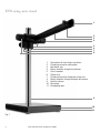
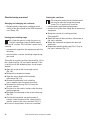
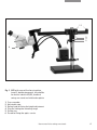
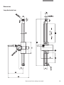
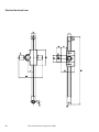
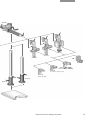
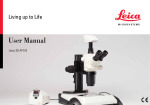
Leica swing-arm
stands
User manual
ESD swing-arm stand
1
2
3
4
5
6
7
8
1
2
3
4
5
6
7
8
9
10
11
Connection for focusing arms/drives
Clamping screw for connection
Horizontal arm
Rotary knob for fixing the cantilever
Cross-member
Safety ring
Clamping screw for fixing the safety ring
Rotary knob for fixing the height adjustment
Vertical column
Baseplate
Dampening feet
9
10
11
Fig. 1
2
User manual Leica swing-arm stands
Standard swing-arm stand
1
2
3
4
5
6
7
8
9
1
2
3
4
5
6
7
8
9
10
11
12
Connection for focusing arms/drives
Clamping lever for connection
Horizontal arm
Rotary knob for fixing the cantilever
Cross-member
Rotary knob for fixing the height adjustment
Plug for limiting the swiveling range
Safety ring
Clamping lever for fixing the safety ring
Vertical column
Baseplate
Dampening feet
10
11
12
Fig. 2
User manual Leica swing-arm stands
3
Large swing-arm stand
1
2
3
4
5
6
7
8
1
2
3
4
5
6
7
8
9
10
11
12
13
14
Connection for focusing arms/drives
Clamping lever for connection
Horizontal arm
Rotary knob for fixing the height adjustment
Cross-member
Rotary knob for fixing the cantilever
Screw for setting the rheostat
Crank for height adjustment
Rack on vertical column
Ring for limiting the swiveling range
Clamping lever for fixing the ring
Clamping lever for fixing the vertical column
Baseplate
Dampening feet
9
10
11
12
13
14
Fig. 1
4
User manual Leica swing-arm stands
User manual Leica swing-arm stands
5
6
User manual Leica swing-arm stands
Dear User,
Thank you for your choosing our products. We hope that you
will enjoy the quality and performance of Leica Microsystems
products.
In developing our instruments, we place great value on simple,
self-explanatory operation. Nevertheless, please take the time
and read the operating instructions so that you know the benefits and possibilities your Leica swing-arm stand offers and can
utilize them to your advantage. Should you ever have any
questions, please consult your local Leica representative.
You will find the address of the closest local representative as
well as valuable information about products and services from
Leica Microsystems on our homepage at
www.leica-microsystems.com
We are gladly at your service. Customer service is a big thing
with us. Not only before the sale, but afterwards as well.
Leica Microsystems (Switzerland) Ltd.
Stereo & Macroscope Systems
www.stereomicroscopy.com
The user manual
These operating instructions are available in 20 additional
languages on the interactive CD-ROM.
User manuals and updates are available for you to download
from our web site at www.stereomicroscopy.com.
The present operating instructions contain descriptions of the
safety instructions, setup, handling and accessories
of the ESD, standard and large swing-arm stands.
User manual Leica swing-arm stands
7
Contents
Page
Introduction
Overview of ESD swing-arm stand . . . . . . . . . . . . . . . . . . . . . . . . . 2
Overview of standard swing-arm stand . . . . . . . . . . . . . . . . . . . . . 2
Overview of large swing-arm stand . . . . . . . . . . . . . . . . . . . . . . . . 4
Contents . . . . . . . . . . . . . . . . . . . . . . . . . . . . . . . . . . . . . . . . . . . . . . . .8
Safety concept . . . . . . . . . . . . . . . . . . . . . . . . . . . . . . . . . . . . . . . . . .9
General safety instructions . . . . . . . . . . . . . . . . . . . . . . . . . . . .10-11
General safety instructions of swing-arm stand . . . . . . . . . .12-13
Assembly
ESD and standard swing-arm stands . . . . . . . . . . . . . . . . . . .14-16
Large swing-arm stand . . . . . . . . . . . . . . . . . . . . . . . . . . . . . . . 18-19
Focusing arms and drives . . . . . . . . . . . . . . . . . . . . . . . . . . . . .20-21
Microscope carrier/stereomicroscope . . . . . . . . . . . . . . . . . . . .22
Operation
ESD swing-arm stand . . . . . . . . . . . . . . . . . . . . . . . . . . . . . . . . 24-25
Standard swing-arm stand . . . . . . . . . . . . . . . . . . . . . . . . . . . . 26-27
Large swing-arm stand . . . . . . . . . . . . . . . . . . . . . . . . . . . . . . . 28-29
Leaving the workplace . . . . . . . . . . . . . . . . . . . . . . . . . . . . . . . . . . .30
Transport of swing-arm stands . . . . . . . . . . . . . . . . . . . . . . . . . . . .30
Starting position . . . . . . . . . . . . . . . . . . . . . . . . . . . . . . . . . . . . . . . .31
Notes about horizontal swinging . . . . . . . . . . . . . . . . . . . . . . .32-33
Table of permissible equipment weights . . . . . . . . . . . . . . . . .34-35
List of typical equipment weights . . . . . . . . . . . . . . . . . . . . . . .36-37
Appendix
Technical data . . . . . . . . . . . . . . . . . . . . . . . . . . . . . . . . . . . . . . . . . .38
Dimensions . . . . . . . . . . . . . . . . . . . . . . . . . . . . . . . . . . . . . . . . . 39-44
Part numbers . . . . . . . . . . . . . . . . . . . . . . . . . . . . . . . . . . . . . . . . . . .45
Assembly diagram of swing-arm stands . . . . . . . . . . . . . . . . .46-47
8
User manual Leica swing-arm stands
Safety concept
General notes
Before startup, read the operating instructions and
safety instructions.
Intended use
The Leica swing-arm stands are mechanical devices that help in
expanding the range of your stereomicroscopes and macroscopes and to move them across large work specimens. Illuminations and various accessory modules, e.g. for photography, TV,
second-observer tube and more, complement the equipment.
Improper use
• If the instrument is used in any other way than described in
these instructions, it may result in injuries to persons or
damages to property.
• Never disassemble mechanical parts if not specifically
instructed to in this manual.
Place of use
Use
in ESD-protected
rooms
• The Leica swing-arm stands are intended primarily for use in
closed rooms.
• If the swing-arm stand is used outdoors, it must be protected
against dust and moisture. Electrically operated illuminations
must not be used outdoors.
The ESD standard and large swing-arm stands consist of an
ESD-discharging material so that they counteract the buildup of
electrostatic charges.
User manual Leica swing-arm stands
9
General safety instructions
Service work
Responsibilities of the
person(s) in charge of
instrument
Repair work must only be performed by Leica-trained service
technicians. Only original Leica spare parts may be used.
• Ensure that the operating personnel has read and understood
this manual and particularly the safety instructions.
• Ensure that only authorized and trained personnel operates,
services and maintains the Leica swing-arm stands.
Workplaces with swing-arm stands facilitate and improve
working with large specimens, but they also impose demands
on concentration ability, viewing and muscular support on part
of the user. Depending on the duration of uninterrupted work,
asthenopia and musculoskeletal problems may occur. For this
reason, appropriate measures for reduction of the workload
must be taken:
• optimal arrangement of workplace, work assignments and
work flow (changing tasks frequently).
• thorough training of the personnel, giving consideration to
ergonomic and organization aspects.
The ergonomic optics concept the of Leica stereomicroscopes
and the design of the swing-arm stands aim to limit the strain
on the user to the lowest possible level.
10
User manual Leica swing-arm stands
Integration in
third-party products
When installing Leica products into third-party products,
note the following:
The manufacturer of the complete system or its dealer is
responsible for following all applicable safety instructions,
laws and guidelines.
Legal requirements
Adhere to general and local regulations relating to accident
prevention and environmental protection.
Disposal
The product must be disposed of in accordance with locally
applicable laws and regulations.
Symbol used in the operating instructions
Safety instructions
This symbol indicates especially important information that,
if not observed,
• can cause hazards to personnel
• can lead to functional disturbances and damaged
instruments
Important information
This symbol indicates additional information or explanations
that intend to provide clarity.
Action
왘 This symbol refers to actions described in the text that are to
be carried out.
Explanatory notes
• This symbol indicates additional notes and explanations
provided in the text.
User manual Leica swing-arm stands
11
General safety instructions of swing-arm stands
The use of your Leica swing-arm stand requires adhering to the safety instructions in
this manual to prevent injuries to yourself or damages to your Leica stereomicroscope
equipment and work environment.
Setup of swing-arm stands
Use of flange and stage clamp
The baseplate of the swing-arm stands
consists of heavy metal parts. If it is used
improperly, it can cause injuries or
damages to the work environment or your Leica
stereomicroscope equipment due to its weight.
Flange and stage clamp are accessories
for mounting the vertical column at your
workplace. Since they support the entire
stereomicroscope equipment, special care must
be paid when attaching them.
• Perform the setup of the swing-arm stand with
two persons so that one person can always secure the parts to be assembled. (Fig. 1)
• Use a slipfree underlay (e.g. a rubber mat) for
the assembly of the vertical column on the
baseplate so that the baseplate cannot slide or
slip.
• Always use a flat even surface for the baseplate.
• To fasten the stage clamp (Fig. 4.1), use a
sufficiently thick (21-70mm) and solid worktop.
• Check the correct seat of the stage clamp at
regular intervals and retighten, if necessary.
• Ensure that technical personnel selects
the correct type of screws and screw lengths
for the respective support during the assembly
of the flange.
The safety ring (for ESD and standard
horizontal arms) protects the horizontal
arm from inadvertently falling down.
• Reposition the retaining ring (Fig. 2.2) after every
change in position at the horizontal arm
and tighten the clamping screw or lever (Fig. 2.1).
The retaining washer (Fig. 3.1) allows for
freely swinging the focusing drive
across the object, even if the plug is
mounted from below. It also protects your
stereomicroscope from inadvertently
falling out if you want to open the clamping lever
(Fig. 3.2) during your work.
The clamping lever or screw at the focusing arm (Fig. 3.3) must be tightened
before inserting the stereomicroscope in
the carrier.
12
During the work
Leica swing-arm stands are optimized to
provide maximum flexibility with minimum weight and space requirements.
To be able to use the full performance of your
swing-arm stand, the following steps must be
observed:
• Before changing the stereomicroscope, bring
your stand to the starting position.
(See page 31)
• Before you continue to work with a modified
equipment, observe the notes about horizontal
swinging. (Page 32)
Transport of swing-arm stands
Please read the notes on p. 30 concerning the safe disassembly and transport
of the swing-arm stand.
User manual Leica swing-arm stands
1
2
Fig. 1
Fig. 2
1
2
3
Fig. 3
Fig. 4
Fig. 1 Assembly of vertical column to the base
plate with two persons
Fig. 2 ESD horizontal arm with cross-member
and safety ring on column 470/35
Fig. 3 Standard horizontal arm with focusing arm
mounted from the top
1 Retaining washer
2 Clamping lever at horizontal arm
3 Hexagon-head screw for fixing the tilt at the
focusing arm
1 Clamping screw at safety ring
2 Safety ring
Fig. 4 Stage clamp for ESD and standard
horizontal arm
User manual Leica swing-arm stands
13
Assembly of ESD and standard swing-arm stands
Corresponding to their function, the swing-arm stands consist of solid, heavy metal parts.
While unpacking, ensure that nobody can be injured by falling or tipping parts.
The assembly of baseplate and vertical column must always be performed by two persons.
Additional safety instructions on page 12 must be observed.
Vertical column ➜ baseplate
Two persons are needed for the assembly of the small and midsize baseplates
to the vertical column 470/35 to prevent
the plate from tipping over and causing any
damages!
Vertical column ➜ flange
왘 Slide the threaded bolt from underneath
through the correct bore hole.
왘 Place the serrated lock washer on the bolt.
왘 Bolt the vertical column and flange together
using the Allen key.
왘 Place the baseplate on a slipfree surface.
왘 Slide the threaded bolt from underneath
through the baseplate.
The flange (Fig. 4) must be fastened at
the workplace by qualified personnel
and regularly checked for firm seat.
왘 Place the serrated lock washer on the bolt
(Fig. 2.1).
왘 While one person secures the base, the second
person tightens the vertical column (Fig. 1)!
Vertical column ➜ stage clamp
왘 Slide the threaded bolt from underneath
through the correct bore hole.
왘 Place the serrated lock washer on the bolt.
왘 Screw the vertical column and stage clamp
together. (Fig. 3)
왘 Fasten the stage clamp together with the
vertical column to the desired position on your
worktop.
Ensure that the worktop (thickness: 2170mm) is suitable to provide
sufficient support for the swing-arm
stand including the equipment.
Check the firm seat of the stage clamp
at the worktop at regular intervals.
14
User manual Leica swing-arm stands
The four screws for fastening the flange
are not part of the standard delivery
since length and type of screw must be
adapted to the supporting surface.
1
Fig. 1
Fig. 2
Fig. 3
Fig. 4
Fig. 1 Assembly of vertical column to the base
plate with two persons
Fig. 2 Baseplate with hexagon-head screw and
serrated lock washer for the assembly of
the ESD and standard horizontal arms
Fig. 3 Assembly of the vertical column 470/35 to
the stage clamp
1 Serrated lock washer
Fig. 4 Flange for permanent assembly of the
vertical column 470/35
User manual Leica swing-arm stands
15
Safety ring ➜ vertical column
왘 Slide the safety ring over the column (Fig. 1.3).
왘 Tighten the clamping screw (ESD) or the
clamping lever (standard) (Fig. 1.2).
1
Horizontal arm ➜ vertical column
왘 Open the rotary knob for the height adjustment
(Fig. 1.1).
왘 Carefully place the horizontal arm on the
vertical column until it sits on the safety ring.
왘 Align the horizontal arm parallel to the long side
of the baseplate.
왘 Retighten the rotary knob (Fig. 1.1) for the height
adjustment.
2
3
Fig. 1
Alignment of clamping levers
• At the standard and large horizontal arms, the
clamping levers can be turned to any position
after tightening to provide you with the largest
possible freedom of movement:
왘 Tighten the respective clamping lever.
왘 Pull the clamping lever out in its axis (Fig. 2).
왘 Turn the lever to the desired
position and release it.
Fig. 2
Assembly of focusing arms and drives
To assemble the focusing arms and drives, please
continue on page 20.
Fig. 1 ESD horizontal arm with cross-member and
safety ring on vertical column 470/35
1 Rotary knob for fixing the cantilever
2 Clamping screw at safety ring
3 Safety ring
Fig. 2 Clamping lever at safety ring of the
standard horizontal arm
16
User manual Leica swing-arm stands
User manual Leica swing-arm stands
17
Assembly of the large swing-arm stand
Vertical column ➜ baseplate
Fig. 1 Assembly of vertical column 560/57 or
800/57 onto the large baseplate
Two persons are needed for the assembly of the large baseplate to the vertical
column 560/57 and 800/57 to prevent the
column from tipping over and causing any
damages!
1 The rack is positioned in the direction of the
cutout of the base
2 The vertical column is fastened with four
hexagon-head screws
왘 Position the vertical column with the rack
(Fig. 1.1) towards the cutout of the base so that
the four bore holes in the base align with the
four threaded holes on the plate.
왘 While one person secures the vertical column,
the second person tightens the column with the
four hexagon-head screws. (Fig.1.2)
Fig. 2 Hexagon-head screw at the head of the
vertical column 560/57 or 800/57
Fig. 3 The cross-member at the large horizontal
arm is carefully placed on the vertical
column.
Horizontal arm ➜ vertical column
왘 Open the rotary knob for the height adjustment
(p. 4, Fig. 1.4).
왘 Remove the screw at the head of the vertical
column (Fig. 2.1).
왘 Carefully place the horizontal arm on the
vertical column until it sits on the rack (Fig. 3).
왘 Carefully turn the crank several turns until the
worm in the cross-member is completely
meshed with the rack and the upper end of the
rack reappears.
왘 Reinsert the previously removed screw at the
head of the vertical column (Fig. 2.1).
왘 Retighten the rotary knob for the height
adjustment (p. 4, Fig. 1.4).
Use of clamping levers
To use the clamping levers, please continue
on page 16.
Assembly of focusing arms and drives
To assemble the focusing arms and drives, please
continue on page 20.
18
User manual Leica swing-arm stands
1
2
Fig. 1
1
Fig. 2
Fig. 3
User manual Leica swing-arm stands
19
Assembly of focusing arms and drives
Focusing arm ➜ horizontal arm
왘 Ensure that the horizontal arm is in the starting
position. (See p. 31).
1 2
왘 Fasten all levers and screws.
왘 Open the lever or the screw at the
focusing arm connection of the horizontal arm.
왘 Remove the retaining washer from the connect-
ing plug of the focusing arm.
왘 Insert the plug (Fig. 1.2) into the socket (Fig. 1.1)
at the horizontal arm.
왘 Close the clamping lever or screw again at the
3
horizontal arm.
• A special case is the combination of carrier rod
(10 447 259) with focusing arm (10 446 344):
왘 Remove the retaining washer from the carrier
rod.
왘 Open the safety screw at the focusing arm.
왘 Slide the focusing arm onto the column.
왘 Close the safety screw.
왘 Fasten the retaining washer again.
왘 Close the clamping lever or screw again at the
horizontal arm.
Fig. 1
1
Assembly of focusing arm plug from the bottom
• On principle, the plug of the focusing arms can
be inserted at the horizontal arm from the top,
the bottom or the front.
• If the plug is attached to the horizontal arm from
the bottom, you must use the retaining washer
(Fig. 2.1):
왘 Screw the retaining washer with the corresponding hexagon-head screw into the threaded hole of the plug at the focusing arm (Fig.2.1).
Fig. 2
Fig. 1 Placing the focusing arm on the horizontal
arm
1 Socket at the horizontal arm
2 Plug of the focusing arm
3 Clamping lever for fixing the focusing arm
Fig. 2 Focusing arm with plug mounted from the
bottom
1 Retaining washer
20
User manual Leica swing-arm stands
Focusing drive ➜ horizontal arm
2
왘 Ensure that the horizontal arm is in the starting
position (see p. 31).
1 2
왘 Fasten all levers and screws.
왘 Open the clamping lever at the focusing drive
connection (Fig. 1.1).
왘 Remove the retaining washer from the
connecting plug of the focusing drive.
왘 Insert the plug (Fig. 1.2) into the socket at the
horizontal arm.
1
왘 Close the clamping lever again (Fig. 1.1).
Fig. 1
Fig. 1 Focusing drive at the large horizontal arm
1 Clamping lever at horizontal arm
2 Plug of the focusing drive
User manual Leica swing-arm stands
21
Assembly of microscope carrier and stereomicroscope
Microscope carrier ➜ focusing drive
왘 Remove the safety screw from the front side of
the focusing drive.
왘 Position the microscope carrier so that the two
1
positioning plugs (Fig. 1.1) lock into the
corresponding recesses at the microscope
carrier.
왘 Insert the safety screw into the bore hole in the
microscope carrier and retighten it with the
Allen key. (Fig. 1.2)
2
Stereomicroscope ➜ optics carrier
왘 Check and fix all levers and screws at the
swing-arm stand and the focusing drive/arm
before inserting the stereomicroscope into the
microscope carrier.
왘 Open the screw (Fig. 2.1) at the ring of the
microscope carrier.
왘 Use both hands and carefully insert the stereomicroscope into the microscope carrier.
(Fig. 2)
왘 Retighten the screw (Fig. 2.1) at the microscope
carrier.
Fig. 1
Additional notes about the assembly of microscope carriers and swing-arm stands
can be found in the operating instructions
M2-105-0en.
Fig. 2
They also contain additional adapters and accessories for attaching illumination to the Leica
swing-arm stands (see the example on page 37).
Fig. 1 Placing the optics carrier on the horizontal
arm
1
1 Connecting plug at the focusing drive
2 Hexagon-head screw for fixing the carrier
Fig. 2 Inserting the stereomicroscope into the
optics carrier
1 Screw for fixing the stereomicroscope
22
User manual Leica swing-arm stands
User manual Leica swing-arm stands
23
Operation of swing-arm stands
The following operating notes show the correct use of your swing-arm stand. Ensure that
only personnel who has read and understood these operating instructions and particularly
the safety instructions is working with a Leica swing-arm stand. In addition, check the correct seat of all levers and screws before every operating step.
ESD swing-arm stand
왘 Retighten the rotary knob for the height
Leica swing-arm stands are optimized
for stability and safe use. Nevertheless,
the wrong combination of equipment,
cantilever and swinging angle can cause the
stand to tip over. For this reason, it is absolutely
necessary to read the safety instructions on
page 12-13.
Changing the cantilever
왘 Close all levers and screws.
왘 Open the rotary knob for the cantilever
adjustment. (Fig. 1.1)
왘 Pull the horizontal arm out of the cross-member
adjustment (Fig. 1.2).
왘 Reposition the safety ring (Fig. 1.4) until it is
below the cross-member.
Changing the equipment
왘 Bring the horizontal arm into the starting
position (see p. 31) before changing the
stereomicroscope or adding additional
equipment to the swing-arm stand.
왘 Ensure that the stand supports the modified
equipment. Notes about equipment weight and
permissible total weights can be found on
pages 32 to 37.
to the required cantilever.
왘 Close the rotary knob at the cross-member.
Lateral swinging of the equipment
Changing the working height
• Reducing the working height:
왘 Open the clamping screw (Fig. 1.3) at the safety
ring (Fig. 1.4) and fix it to the desired working
height.
왘 Open the rotary knob for the height adjustment
(Fig. 1.2) and lower the horizontal arm to the
desired height.
Before you swing the stereomicroscope
across your specimen, it is absolutely
necessary to reposition the safety ring
up to the cross-member and tighten it. Otherwise,
the horizontal arm could fall down if the rotary
knob is loosened (Fig. 1.2) and cause injuries or
damages to equipment and specimens.
왘 Reposition the safety ring (Fig. 1.3) up to the
cross-member and fix it in place.
• Increasing the working height:
왘 Hold the horizontal arm with one hand.
왘 Open the rotary knob for the height adjustment.
(Fig. 1.2)
왘 Push the horizontal arm up until the desired
working height is reached.
24
왘 Open the rotary knob for the height adjustment
(Fig. 1.1) at the cross-member.
왘 Swing your equipment into the desired position.
왘 Fix the height adjustment again.
User manual Leica swing-arm stands
1
2
3
4
Fig. 1
Fig. 1 Leica S6 at the ESD horizontal arm
with safety ring on vertical column 470/35
1
2
3
4
Rotary knob for fixing the cantilever
Rotary knob for fixing the height adjustment
Clamping screw for fixing the safety ring
Safety ring
User manual Leica swing-arm stands
25
Standard swing-arm stand
Swinging and changing the cantilever
• Swinging and changing the cantilever work
similar to the description of the ESD horizontal
arm. (See p. 24)
Limiting the cantilever
The maximum extension for the horizontal
arm can be adjusted using the limiting
screw. This is particularly useful to
• conveniently reposition the equipment
• prevent the system from tilting due to excessive
equipment
왘 Bring the stand to its starting position.
Limiting the swiveling range
By using the special safety ring, you can
limit the swiveling range of the horizontal
arm to a 90° section. This function is particularly
useful to
• conveniently reposition the equipment with the
limitation
• remain within a certain swiveling range during
your work
(See page 31).
왘 Open the lever of the cantilever adjustment at
the cross-member.
왘 Move the stereomicroscope to the desired
extension.
왘 Reposition the adjustable stop (Fig. 1.2) up to
the cross-member (Fig. 1.1).
To be able to use this function, the plug (Fig. 1.4) at
the safety ring (Fig. 1.5) must point upward. If this
is not the case, the following steps are to be performed:
왘 Open the screw at the microscope carrier
(Fig. 1.6).
왘 Remove the stereomicroscope.
왘 Open the rotary knob to fix the height
adjustment (Fig. 1.3).
왘 Remove the horizontal arm including
cross-member from the vertical column.
왘 Remove the safety ring (Fig. 1.5) from the
vertical column.
왘 Position it on the vertical column with the plug
pointing upward.
왘 Retighten the clamping screw at the safety ring
(Fig. 1.5).
왘 Position the horizontal arm on the vertical
column so that the plug at the safety ring fits
into the cutout at the cross-member (Fig. 1.1).
왘 Fasten all rotary knobs at the cross-member.
26
User manual Leica swing-arm stands
12
3
4
5
6
Fig. 1 MS5 with coarse/fine focusing drive,
lamp L2, double gooseneck, lamp holder
for vertical column 470/35, standard
swing-arm stand and midsize baseplate
1
2
3
4
5
6
Cross-member
Adjustable stop
Rotary knob for fixing the height adjustment
Plug for limiting the swiveling range
Safety ring
Screw for fixing the optics carrier
User manual Leica swing-arm stands
27
Large swing-arm stand
Limiting the cantilever
Changing the working height
The maximum extension for the horizontal arm
can be adjusted using the adjustable stop.
The procedure is identical to the standard
horizontal arm described on page 26.
왘 Close the rotary knob to fix the cantilever
(Fig. 1.2).
왘 Open the rotary knob to fix the height
adjustment at the cross-member (Fig. 1.1).
왘 Use the crank (Fig. 1.4) to move the system to
the desired working height.
왘 Close the rotary knob again to fix the height
adjustment (Fig. 1.1)
The rheostat of the crank can be adjusted
continuously using the supplied Allen key.
This is necessary depending upon the desired
force expenditure and weight of the equipment.
왘 Adjust the hexagon-head screw with the
supplied key using quarter turns. (Fig. 1.3)
• Tightening the screw clockwise increases the
rheostat, loosening the screw counterclockwise reduces it.
Never force the crank; otherwise, it may
damage the rack or pinion. If it is very
difficult to turn, check the following
items:
• Is the upper screw at the cross-member
closed? If so, open it.
• Is the hexagon-head screw at the crank tightened too much? If so, open it in increments.
Changing the cantilever
왘 Close the rotary knob to fix the height
adjustment (Fig. 1.1)
왘 Open the rotary knob to fix the cantilever
(Fig. 1.2).
왘 Pull the horizontal arm out of the cross-member
to the intended cantilever.
왘 Close the rotary knob to fix the cantilever
(Fig. 1.2).
28
Swinging the horizontal arm
The lateral swinging is enabled via the lever at the
base of the vertical column:
왘 Close the two rotary knobs at the
cross-member (Fig. 1.1 and 1.2).
왘 Open the clamping lever at the base of the
vertical column. (Fig. 1.8)
왘 Rotate the stereomicroscope to the desired
position.
왘 Close the clamping lever again.
Limiting the swiveling range
The swiveling range can also be limited at
the large swing-arm stand to a freely
selectable 90° sector. This function is performed
by the ring at the base of the vertical column
(Fig. 1.7):
왘 Open the clamping lever for the lateral
swiveling limitation. (Fig. 1.6)
왘 Swing the stereomicroscope to the desired
starting position as described above.
왘 Turn the ring (Fig. 1.7) up to one of the two stops.
왘 Close the clamping lever again. (Fig. 1.6)
왘 Leave the clamping lever open if you do not want
to limit the swiveling range.
The ring at the base of the vertical
column (Fig. 1.7) must be fixed with the
clamping lever so that it rests on the base
(Fig. 1.9). Other assembly positions can damage the
rack (Fig. 1.5) at the vertical column.
User manual Leica swing-arm stands
1
2
3
4
5
6
7
8
9
Fig. 1
Fig. 1 MZ16 with Leica digital camera DFC300,
coarse/fine focusing drive and large
swing-arm stand
1
2
3
4
5
6
7
8
9
Rotary knob for fixing the height adjustment
Rotary knob for fixing the cantilever
Hex bit for adjusting the rheostat
Crank for height adjustment
Rack
Clamping lever at the ring
Ring at the base of the vertical column
Clamping lever for fixing the vertical column
Base of vertical column
User manual Leica swing-arm stands
29
Leaving the workplace
Protect other persons and your workplace against injuries or damages by
securing your swing-arm stand before
leaving the workplace:
왘 Return the swing-arm stand to the starting
position (see p. 31).
왘 Fix all rotary knobs, clamping levers and screws
to prevent any inadvertent movement of the
swing-arm stand.
Transport of swing-arm stands
Leica swing-arm stands consist of
heavy metal parts. If you intend to
disassemble a stand at one workplace
and move it to another workplace, please observe the following notes:
Fig. 1
Fig. 1 Large baseplate with recessed grip
왘 Always transport the baseplate with mounted
vertical column using two persons.
왘 Remove the stereomicroscope from the
focusing drive/arm.
왘 Remove the horizontal arm including
cross-member from the vertical column.
왘 The large baseplate features a recessed grip at
one side that facilitates the transport. (Fig. 1)
왘 For transport over longer distances use a suit-
able transport tool, such as a trolley.
30
User manual Leica swing-arm stands
Starting position
The following operating instructions can be used to determine whether the total
weight of your stereomicroscope equipment is suitable for the intended cantilever and
the swiveling range. These instructions must be followed and you must ensure that all
personnel working with Leica swing-arm stands have read and understood these
instructions.
The starting position prevents damages
from a tilting stand. The swing-arm
stand must be brought to the starting
position (Fig. 2) before you:
• remove your stereomicroscope from the
microscope carrier.
• change accessories such as illumination or
ErgoModules.
• leave your workplace.
왘 Align the horizontal arm parallel to the long side
of the baseplate. (Fig. 1)
왘 Retract the cantilever of the horizontal arm up
to the cross-member. (Fig. 2)
왘 Ensure that all rotary knobs and clamping
Fig. 1
levers or screws are fixed.
Fig. 2
Fig. 1 Large horizontal arm aligned parallel to the
long side of the baseplate
Fig. 2 Large horizontal arm in starting position
User manual Leica swing-arm stands
31
Notes about horizontal swinging
Leica swing-arm stands are optimized for maximum range and stability. Nevertheless,
the wrong combination of weight, cantilever and swinging angle can cause the stand to
tip over.
Selecting a safe swinging angle
Examples for a typical application
• The maximum permissible carrying load of your
Leica swing-arm stand can be found in the
corresponding table on page 34/35.
• Starting with the zero position (Fig. 1.1), you can
swing up to ±30° with the maximum carrying
load. (Fig. 1)
• For swinging angles >30° (Fig. 2), you must
reduce either the weight or the cantilever at the
stand. (Fig. 2)
• A list of typical equipment weights can be found
on page 36/37.
The following example demonstrates how you can
determine whether the planned combination of
stereomicroscope, equipment and swing-arm
stand is permissible:
왘 Before you continue working at the swing-arm
stand with a modified equipment, you must
carefully test the combination of intended
cantilever and required swinging angle.
• You want to use a standard horizontal arm with
midsize base and inclinable focusing drive
(10 447 256).
• The table on page 34 shows that this combination allows for a maximum carrying load of 5.2kg
in the zero position (Fig. 1.1).
• You intend to use the following stereomicroscope equipment with this swing-arm stand:
Leica MZ6
10 445 614
10 445 619
10 447 160
10 422 563
Leica MZ6 optics carrier
Inclined binocular tube 45°
2 eyepieces 10x/21B, adjustable
Objective achromat 0.5x, M-series
This combination has a total weight of 1.8kg (list on
page 36) and, therefore, can be used without
problems in the range of ±30° at full cantilever!
Fig. 1 Optimum swiveling range of the horizontal
arm with maximum carrying load
Fig. 2 Swiveling range in which cantilever and
swinging angle must be carefully matched
to the selected carrying load
32
User manual Leica swing-arm stands
1.1
Fig. 1
Fig. 2
User manual Leica swing-arm stands
33
Table of permissible equipment weights
The following table provides information about the permissible carrying load dependent upon the horizontal arm, vertical column, baseplate and focusing arm or drive used. The maximum value applies to the respective swing-arm stand in the starting position (page 29).
Horizontal
arm
with column
10 447 097 with
10 447 008
10 447 098 with
10 447 008
Focusing arm / focusing drive
Baseplate
34
10 447 260
10 446 436
10 447 254/
10 447 255
3.2kg
6.6kg
3.2kg
6.6kg
10 447259 &
10 446 344
3.6kg
8kg
3.6kg
4.6kg
10 447 256
X
X
2kg
5.2kg
10 447 257
X
X
X
4.6kg
10 447 258
X
X
X
X
User manual Leica swing-arm stands
10 447 260
10 446 436
Horizontal
arm
with column
10 447 099 with
10 447 014
10 447 099 with
10 447 230
Focusing arm / focusing drive
Baseplate
10 446 437
10 446 437
10 447 254/
10 447 255
14kg
13kg
10 447259 &
10 446 344
14.5kg
13.5kg
10 447 256
13.5kg
12.5kg
10 447 257
11kg
11kg
10 447 258
11kg
10.5kg
User manual Leica swing-arm stands
35
List of typical equipment weights
The following listing provides an overview
of the total weight of different typical types
of equipment. Together with the table on page
34/35, it provides you with an estimate of whether
the required swinging angle and the cantilever
are compatible with the intended
equipment.
Leica S8 APO
10 446 298 Leica S8 APO StereoZoom
10 446 261 Video objective 0.63x
10 446 337 Objective apochromate 2.0x
12 730 044 DFC 480, including cable
10 447 131 2 eyepieces 10x/23
Total weight of outfit 2.9kg
Leica S6 E
10 446 294 Leica S6 E StereoZoom
10 447 130 Eyepiece 10x/23
10 447 131 Eyepiece 10x/23,
10 446 323 ErgoLens® 0.6x-0.75x
Total weight 1.7kg
Leica MZ6
10 445 614 Leica MZ6 optics carrier
10 445 619 Inclined binocular tube 45°
10 447 160 2 eyepieces 10x/21B, adjustable
10 422 563 Objective achromat 0.5x, M-series
Total weight 1.8kg
Leica MZ75
10 446 371 Leica MZ75, optics carrier
10 446 275 Objective plan 1.0x, M-series
10 445 822 ErgoTube® 10°-50°
10 447 160 2 eyepieces 10x/21B, adjustable
10 446 309 Leica photo tube HD F
10 446 261 Video/photo objective 0.63x
12 730 044 DFC480
Total weight 4.8kg
36
Leica MZ95
10 446 272 Leica MZ95 optics carrier
10 446 275 Objective plan, 1.0x, M-series
10 445 924 Trinocular tube, M-series
10 447 160 2 eyepieces 10x/21B, adjustable
10 446 261 Video/photo objective 0.63x
12 730 044 DFC 480
30 120 201 Ringlight RL-66/750
Total weight 4.6kg
Leica MZ125
10 446 370 Leica MZ125 optics carrier
10 447 160 2 eyepieces 10x/21B, adjustable
10 445 819 Objective plan 1.0x, M-series,
10 445 822 ErgoTube® with variable angle 10°-50°
Total weight 3.7kg
Leica MZ125
10 446 370 Leica MZ125 optics carrier
10 445 924 Trinocular tube, M-series
10 447 160 2 eyepieces 10x/21B, adjustable
10 445 819 Objective plan 1.0x, M-series,
10 446 123 ErgoWedge® 5-25°
10 446 261 Video/photo objective 0.63x
12 730 018 DC500
30 120 201 Ringlight RL-66/750
Total weight 5.2kg
Leica MZ16
10 447 102 Leica MZ16 optics carrier with zoom
10 447 160 2 eyepieces 10x/21B, adjustable
10 447 157
Objective planapo 1.0x, M-series,
WD=55mm
10 445 924 Trinocular tube, M-series
10 446 261 Video/photo objective 0.63x
12 730 044 DFC480
30 120 201 Ringlight RL-66/750
Total weight 5.7kg
User manual Leica swing-arm stands
Leica MZ16 A
10 447 103 Leica MZ16 A optics carrier
10 447 160 2 eyepieces 10x/21B, adjustable
10 445 822 ErgoTube® 10°-50°
10 446 309 Docu Tube HD V
10 447 075 Objective plan 0.8x LWD, M-series
10 446 261 Video/photo objective 0.63x
12 730 044 DFC480
30 120 201 Ringlight RL-66/750
Total weight 6.9kg
Leica MZ16 FA
10 447 063 Leica MZ16 FA optics carrier
11 504 069 Lamp housing
10 447 160 2 eyepieces 10x/21B, adjustable
10 445 924 Trinocular tube, M-series
10 447 157 Objective planapo 1.0x, M-series,
WD=55m
10 446 261 Video/photo objective 0.63x
12 730 044 DFC480
Total weight 9.2kg
User manual Leica swing-arm stands
37
Technical data
Large horizontal arm
Type
Max. cantilever:
Max. carrying load:
Standard horizontal arm
Type
Max. cantilever:
Max. carrying load:
ESD horizontal arm
Type
Max. cantilever:
Max. carrying load:
Vertical columns
Vertical column 800/57
Vertical column 560/57
Vertical column 470/35
Baseplates
Large baseplate
Midsize baseplate
Small baseplate
38
Horizontal swing arm for Leica stereomicroscopes and macroscopes;
360° swinging angle with optional 90° sector limitation
Adjustable stop to limit the cantilever
Height adjustment via rack
560mm
20kg (without focusing arm or drive)
Horizontal swing arm for Leica stereomicroscopes and macroscopes;
360° swinging angle with optional 90° sector limitation
Adjustable stop to limit the cantilever
476mm
13.2kg (without focusing arm or drive, with midsize baseplate)
Horizontal swing arm for Leica stereomicroscopes and macroscopes;
360° swinging angle
452mm
6.6kg (without focusing arm or drive; with small baseplate)
Vertical column for large horizontal arm
Height: 800mm, diameter: 57mm
Anodized aluminum; rack for height adjustment;
Clamping lever for fixing horizontal swinging
Clamping lever for fixing swinging range
Vertical column for large horizontal arm
Height: 560mm, diameter: 57mm
Anodized aluminum;
Rack for height adjustment
Clamping lever for fixing horizontal swinging
Clamping lever for fixing swinging range
Vertical column for ESD/standard horizontal arm
Height: 470mm, diameter: 35mm
Chrome-plated steel
Baseplate for large horizontal arm
WxHxD: 400x300x28.5mm
Weight: 20kg
Baseplate for standard and ESD horizontal arm
WxHxD: 330x220x33.5mm
Weight: 17kg
Baseplate for standard and ESD horizontal arm
WxHxD: 260x220x33.5mm
Weight: 13.5kg
User manual Leica swing-arm stands
Dimensions
Large horizontal arm
User manual Leica swing-arm stands
39
Standard horizontal arm
40
User manual Leica swing-arm stands
ESD horizontal arm
User manual Leica swing-arm stands
41
Vertical column 800/57
Vertical column 560/57
Vertical column 470/35
42
User manual Leica swing-arm stands
Flange
Stage clamp
User manual Leica swing-arm stands
43
Large, midsize and small baseplates
44
User manual Leica swing-arm stands
Part numbers with short descriptions
10 447 097
10 447 098
10 447 008
10 447 260
10 446 436
10 447 006
10 447 007
ESD horizontal arm
Standard horizontal arm
Vertical column 470/35mm
Baseplate, small
Baseplate, midsize
Flange
Table clamp
10 447 254
10 447 255
10 447 259
10 446 344
Focusing drive, inclinable, M series
Focusing drive, inclinable, S series / Z series
Carrier rod, inclinable, ∅ 25mm
Focusing arm, for columns with ∅ 25mm
10 447 099
10 447 014
10 447 230
10 446 437
Horizontal arm, large
Vertical column 560/57mm
Vertical column 800/57mm
Baseplate, large
10 447 256
10 447 257
10 447 258
10 447 196
10 446 394
10 445 617
10 447 114
10 447 062
Focusing drive, inclinable
Coarse/fine focusing drive, inclinable
Motorized focus, inclinable, 300mm
Microscope carrier for Z series
Microscope carrier for S-series / Z-series
Microscope carrier for MS5 – MZ95
Microscope carrier for MZ125 – MZ16 A
Microscope carrier AX for MZ125 – MZ16 A
User manual Leica swing-arm stands
45
Assembly diagram of swing-arm stands
10 447 098
10 447 097
10 447 259
10 447 255
for S-Series / Z-Series (A,Y)
10 447 254
for M-Series
10 446 344
for S-Series / Z-Series (A,Y)
10 447 008
10 447 006
10 447 260
10 447 007
10 446 436
46
User manual Leica swing-arm stands
10 447 099
10 447 258
10 447 257
10 447 256
AX
10 447 062
10 445 617 MS5 - MZ9s
10 447 114 MZ12s - MZ16 A
10 446 394
for S-Series / Z-Series (A,Y)
10 447 196
for Z-Series (AS)
10 447 014
10 447 230
10 446 437
User manual Leica swing-arm stands
47
Leica Microsystems – the brand
for outstanding products
Leica, the leading brand for microscopes and scientific instruments, developed from
five brand names, all with a long tradition: Wild, Leitz, Reichert, Jung and Cambridge
Instruments. Yet Leica symbolizes innovation as well as tradition.
Leica Microsystems – an international company
with a strong network of customer services
Australia:
Austria:
Canada:
China:
Denmark:
France:
Gladesville, NSW
Vienna
Richmond Hill/Ontario
Hong Kong
Herlev
Rueil-Malmaison
Cédex
Bensheim
Milan
Tokyo
Seoul
Rijswijk
Lisbon
Germany:
Italy:
Japan:
Korea:
Netherlands:
Portugal:
Singapore:
Spain:
Barcelona
Sweden:
Sollentuna
Switzerland:
Glattbrugg
United Kingdom: Milton Keynes
USA:
Bannockburn/Illinois
Tel.
Tel.
Tel.
Tel.
Tel.
+1 800 625 286
+43 1 486 80 50 0
+1 905 762 20 00
+8522 564 6699
+45 44 5401 01
Fax
Fax
Fax
Fax
Fax
+61 2 9817 8358
+43 1 486 80 50 30
+1 905 762 89 37
+8522 564 4163
+45 44 5401 11
Tel.
Tel.
Tel.
Tel.
Tel.
Tel.
Tel.
Tel.
Tel.
Tel.
Tel.
Tel.
Tel.
+33 1 4732 8585
+49 6251 1360
+39 02 57 486 1
+81 3 543 596 09
+82 2 514 6543
+31 70 41 32 130
+35 1 213 814 766
+65 6 77 97 823
+34 93 494 9530
+46 8 625 45 45
+41 44 809 34 34
+44 1908 246 246
+1 800 248 0123
Fax
Fax
Fax
Fax
Fax
Fax
Fax
Fax
Fax
Fax
Fax
Fax
Fax
+33 1 4732 8586
+49 6251 136 155
+39 02 5740 3273
+81 3 543 596 15
+82 2 514 6548
+31 70 41 32 109
+35 1 213 854 668
+65 6 77 30 628
+34 93 494 9532
+46 8 625 45 10
+41 44 809 34 44
+44 1908 609 992
+1 847 405 0164
and representatives of Leica Microsystems
in more than 100 countries.
In accordance with the ISO 9001 certificate, Leica Microsystems (Switzerland) Ltd,
Business Unit Stereo & Macroscope Systems has at its disposal a management system
that meets the requirements of the international standard for quality management. In
addition, production meets the requirements of the international standard ISO 14001 for
environmental management.
Leica Microsystems (Switzerland) Ltd.
Stereo & Macroscope Systems
CH-9435 Heerbrugg
Phone +41 71 726 33 33
Fax +41 71 726 33 99
www.leica-microsystems.com
www.stereomicroscopy.com
The companies of the Leica Microsystems
Group operate internationally in four business
segments, where we rank with the market
leaders.
●
Microscopy Systems
Our expertise in microscopy is the basis for all
our solutions for visualization, measurement
and analysis of microstructures in life sciences
and industry. With confocal laser technology
and image analysis systems, we provide threedimensional viewing facilities and offer new
solutions for cytogenetics, pathology and materials sciences.
●
Specimen Preparation
We provide comprehensive systems and services for clinical histo- and cytopathology
applications, biomedical research and industrial quality assurance. Our product range
includes instruments, systems and consumables for tissue infiltration and embedding,
microtomes and cryostats as well as automated stainers and coverslippers.
●
Medical Equipment
Innovative technologies in our surgical microscopes offer new therapeutic approaches in
microsurgery.
●
Semiconductor Equipment
Our automated, leading-edge measurement and
inspection systems and our E-beam lithography
systems make us the first choice supplier for
semiconductor manufacturers all over the world.
Illustrations, descriptions and technical data not binding – Subject to change without notice.
M2-217-0en • © Leica Microsystems (Switzerland) Ltd. • CH-9435 Heerbrugg, 2005 – en – VII.2005 – RDV
Leica Microsystems’ mission is to be the world’s first-choice provider of innovative
solutions to our customers’ needs for vision, measurement, lithography and analysis
of microstructures.