1
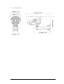
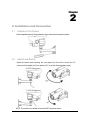
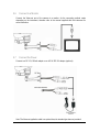
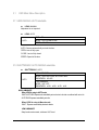
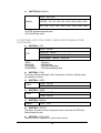
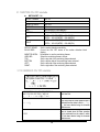
EverFocus Operation Instruction 700TVL High Resolution Day / Night Weather Resistant Outdoor IR Bullet Camera EZ632e EVERFOCUS ELECTRONICS CORPORATION Operation Instruction 2011 EverFocus Electronics Corp Please read this manual first for correct installation and operation. This manual should be retained for future reference. The information in this manual was current when published. The manufacturer reserves the right to revise and improve its products. All specifications are therefore subject to change without notice. All rights reserved. No part of the contents of this manual may be reproduced or transmitted in any form or by any means without written permission of the EverFocus Electronics Corporation. 2 PRECAUTIONS 1. Do not install the camera near electric or magnetic fields. Install the camera away from TV/radio transmitters, magnets, electric motors, transformers and audio speakers since the electromagnetic fields generated from these devices may distort the video image or otherwise interfere with camera operation. 2. Never disassemble the camera beyond the recommendations in this manual nor introduce materials other than those recommended herein. Improper disassembly or introduction of corrosive materials may result in equipment failure or other damage. 3. Try to avoid facing the camera toward the sun. In some circumstances, direct sunlight may cause permanent damage to the sensor and/or internal circuits, as well as creating unbalanced illumination beyond the capability of the camera to compensate. 4. Keep the power cord away from water and other liquids and never touch the power cord with wet hands. Touching a wet power cord with your hands or touching the power cord with wet hands may result in electric shock. 5. Never install the camera in areas exposed to oil, gas or solvents. Oil, gas or solvents may result in equipment failure, electric shock or, in extreme cases, fire. 6. Cleaning For cameras with interchangeable lenses, do not touch the surface of the sensor directly with the hands. Use lens tissue or a cotton tipped applicator and ethanol to clean the sensor and the camera lens. Use a damp soft cloth to remove any dirt from the camera body. Please do not use complex solvents, corrosive or abrasive agents for cleaning of any part of the camera. 7. Do not operate the camera beyond the specified temperature, humidity or power source ratings. This camera is suitable for indoor and outdoor operation. Use the camera at temperatures within -40°C~50°C (-40°F~122°F) and in an IP66 compliant environment; this device is not rated as submersible. The input power source is 12VDC. The use of properly fused or Class 2 power limited type supplies is highly recommended. 8. Mounting Use care in selecting a solid mounting surface which will support the weight of the camera plus any wind, snow, ice or other loading, and securely attach the camera to the mounting surface using screws and anchors which will properly support the camera. If necessary (e.g. when mounting to drop ceilings) use a safety wire to provide additional support for the camera. 3 ATTENTION! This is a class A product which may cause radio interference in a domestic environment; in this case, the user may be urged to take adequate measures. Federal Communication Commission Interference Statement This equipment has been tested and found to comply with the limits for a Class B digital device, pursuant to Part 15 of the FCC Rules. These limits are designed to provide reasonable protection against harmful interference in a residential installation. This equipment generates, uses and can radiate radio frequency energy and, if not installed and used in accordance with the instructions, may cause harmful interference to radio communications. However, there is no guarantee that interference will not occur in a particular installation. If this equipment does cause harmful interference to radio or television reception, which can be determined by turning the equipment off and on, the user is encouraged to try to correct the interference by one of the following measures : •Reorient or relocate the receiving antenna. •Increase the separation between the equipment and receiver. •Connect the equipment into an outlet on a circuit different from that to which the receiver is connected. •Consult the dealer or an experienced radio/TV technician for help. FCC Caution: Any changes or modifications not expressly approved by the party responsible for compliance could void the users’ authority to operate this equipment. 4 Table of Contents 1. PRODUCT OVERVIEW ...................................................................................................................... 6 1.1 1.2 1.3 1.4 FEATURES..................................................................................................................................... 6 ACCESSORY PARTS LIST............................................................................................................... 6 SPECIFICATIONS ........................................................................................................................... 7 DIMENSIONS ................................................................................................................................. 8 2. INSTALLATION AND CONNECTION............................................................................................. 9 2.1 2.2 2.3 2.4 2.5 2.6 2.7 INSTALLATION OF THE CAMERA ................................................................................................... 9 ADJUST 2-AXIS BRACKET ............................................................................................................ 9 FOCUS ADJUSTMENT .................................................................................................................. 10 REMOVE THE CONTROLLER CAP ................................................................................................ 10 INSTALL SUNSHIELD ................................................................................................................... 11 CONNECT TO A MONITOR ........................................................................................................... 12 CONNECT THE POWER ................................................................................................................ 12 3. OSD MENU & CONFIGURATION .................................................................................................. 13 3.1 OSD MAIN MENU DESCRIPTION ................................................................................................ 14 3.1.1 LENS: MANUAL /AUTO selectable. .......................................................................................... 14 3.1.2 SHUTTER/AGC: AUTO / MANUAL selectable. ........................................................................ 14 3.1.3 WHITE BAL: ATW / PUSH / USER1 / USER2 / ANTI CR / MANUAL / PUSH LOCK selectable. ............................................................................................................................................................. 15 3.1.4 BACKLIGHT: BLC / HLC / OFF selectable. ............................................................................. 16 3.1.5 ATR: ON / OFF selectable. ........................................................................................................ 16 3.1.6 NR: ↲ ......................................................................................................................................... 16 3.1.7 PICT ADJUST: ↲ ....................................................................................................................... 16 3.1.8 NEXT: ↲ ..................................................................................................................................... 17 3.1.9 EXIT: ↲ ...................................................................................................................................... 17 3..1.10 SAVE ALL: .............................................................................................................................. 17 3.1.11 PRIVACY: ON / OFF selectable. ............................................................................................. 17 3.1.12 MOTION: ON / OFF selectable. .............................................................................................. 18 3.1.13 CAMERA ID: ON / OFF selectable. ........................................................................................ 18 3.1.14 LANGUAGE ............................................................................................................................. 19 3.1.15 CAMERA RESET...................................................................................................................... 19 3.1.16 BACK ....................................................................................................................................... 19 5 Chapter 1 1. Product Overview Amazing low light sensitivity of 0.03 lux before the added benefits of advanced DSP technology, delivered by a 1/3” Sony Exview HAD CCD II 960H sensor, is just the beginning with the new EverFocus EZ632e. Equip with 42 IR LEDs to get extended IR range, variable output IR control to manage illumination and conserve energy, 700TVL resolution, full motion true day/night images even with no ambient light without ghosting, plus Digital Wide Dynamic Range (Sony ATR technology) smoothly work with BLC, AGC, AWB functions to handle the most challenging of bright or unbalanced scene lighting conditions. Easy to mount and install, Vandal resistant, IP66, with external focal adjustment varifocal auto iris lens and a full suite of OSD Menu and DSP functions controllable at the camera. This is the camera you have been waiting for, and might be the only camera you’ll ever need. 1.1 1.2 Features True Day/Night camera with Sony 1/3” Exview HAD CCD II 960H Sensor, 700 TVL resolution. Sony Effio-E platform to provide advanced camera functions. Vari-Focal DC Iris Lens 3.7~12mm or 9~22mm with ICR. High sensitivity, low smear, high anti-blooming and high S/N ratio for high performance video. True Day/Night with ICR module and 42 IR LEDs reach up to 40m (~130ft.) range. Switchable 10m / 20m / 40m IR Range for different range of requirements. Easy to use OSD Setup Menu. D-WDR functions by Sony ATR technology. Built-in Auto Electronic Shutter (AES), Auto Gain Control (AGC), Back Light Compensation (BLC) and Auto White Balance (AWB). Built-in Motion Detection, Privacy Mask advanced surveillance functions. Internal wire system with anti-cut bracket. Auto Blemish compensation up to 32 points. External manual focus adjustment. Weather Resistant IP66, Vandal Resistant and built-in heater. Accessory Parts List Please be careful when you unpack the box due to the electronics devices inside. Check and make sure that you have all the items listed below inside the original box: EXD330e camera x 1 User Manual x 1 Power adapter pigtail x 1 Mounting template x 1 Accessory kit x 1 (containing mounting screws and plastic anchors) 6 Please Note: If an item appears to have been damaged in shipment, replace it properly in its carton and notify the shipper. If any items are missing, notify your EverFocus Electronics Corp. Sales Representative or Customer Service. The shipping carton is the safest container in which the unit may be transported. Save it for possible future use. 1.3 Specifications Pickup Device Video Format Picture Elements Horizontal Resolution Sensitivity S/N Ratio Electronic Shutter Video Output Gamma Correction Lens Type 1/3" SONY Exview HAD CCD II (960H) NTSC or PAL (depends on model selected) 976 x 494 (NTSC), 976 x 582 (PAL) 700 TVL 0.03 Lux / F=1.2 ; 0 Lux (IR LED On) Over 48dB (AGC off) 1/60 (1/50) ~ 1/100,000s BNC 1.0V p-p 75Ω, 0.45 Vari-Focal DC Iris Lens 3.7~12mm / F1.6 with ICR Vari-Focal DC Iris Lens 9~22mm / F1.6 with ICR Back Light Compensation On /Off Auto Gain Control Yes White Balance Auto / Indoor / Outdoor / Manual / Push Auto Sync. Mode Internal Day & Night True Day/Night with ICR control module OSD menu Yes (English / Japanese / German / French / Russian / Portuguese / Spanish / Simplified Chinese) DNR On / Off D-WDR (ATR) On / Off Mirror On / Off Motion Detection On / Off for 24x16 Detection Blocks Privacy Mask Off/On for 8 Areas (Size Adjustable) IR LED 42 Units IR LED IR Configuration 10m / 20m /40m DIP Switchable IR Wavelength 850nm IR Range 40m max. Power Source 12VDC Power Consumption 12VDC: 24W max. (With Heater Operation) Operating Temperature -40°C~50°C ; -40°F~122°F (built-in heater) Weather Proof IP66 rated Heater Yes, built-in Vandal Resistant Yes Dimensions 109mm(W) x 267mm(L) x 172mm(H) ; 4.3”(W) x 10.5”(L) x 6.8”(H) Weight 1,080g / 2.4 lbs Certifications CE / FCC 7 1.4 Dimensions 8 Chapter 2 2. Installation and Connection 2.1 Installation of the Camera Use the supplied screws (in the appurtenance bag), and secure the camera in position. 2.2 Adjust 2-Axis Bracket Adjust the bracket while checking the view angle from the monitor. Loosen the X-Y screws and then adjust the 2-Axis bracket (X-Y to get the desired viewing angle). NOTE: This product is not suitable for horizontal 360° continuous rotation. 9 2.3 Focus Adjustment Focus adjustment should be done with zoom focus at the same time. Use the screwdriver to adjust the zoom/ focus ratio (from wide to tele or near to far). NOTE: Focus adjustment position may be different depending on model type. 2.4 Remove the Controller Cap Use a coin to remove the controller cap and make adjustments. 10 The Table below shows the suggested LED brightness and IR distance adjustment: LED Brightness H (High) M (Middle) L (Low) IR Distance 25m~40m 15m~25m 10m~15m Focal Length 9~22mm 6~12mm 3.7~6mm (1) Function Switch 1 Left Key 2 Up Key 3 Enter Key 4 Right Key 5 Down (2) IR Distance Adjustment Installer may use IR adjustment function according to installation conditions. It is suggested that the view angle should be verified before setting up the IR distance. 2.5 Install Sunshield To install the sunshield, please follow the instruction shown below: 11 2.6 Connect to a Monitor Connect the Video-out port of the camera to a monitor. As the connecting method varies depending on the instrument, therefore refer to the manual supplied with the instrument for more information. 2.7 Connect the Power Connect to a DC 12V, 500mA adaptor or an AC 24/ DC 12V adaptor (optional). Note: The Alarm out application cable is an optional item, the standard type does not provides it. 12 Chapter 3 3. OSD Menu & Configuration Main Menu Display OSD Setup Menu page 1 AUTO↲ ↲ AUTO↲ ↲ ATW OFF OFF ↲ ↲ LENS SHUTTER /AGC WHITE BAL BACKLIGHT ATR NR PICT ADJUST NEXT↲ ↲ EXIT↲ ↲ SAVE ALL OSD Setup Menu page 2 PRIVACY MOTION DET CAMERA ID LANGUAGE CAMERA RESET BACK↲ ↲ EXIT↲ ↲ SAVE ALL OFF OFF OFF ENGLISH Main Menu Setup • In order to display the setup menu on the screen, set the menu command or press the button panel. Use UP/ DOWN control buttons to select each item. • Use LEFT/ RIGHT control buttons to change the data. • Use MENU control button to ENTER/ EXIT the menu display. • • ↲=ENTER 13 3.1 OSD Main Menu Description 3.1.1 LENS: MANUAL /AUTO selectable. LENS: MAUNAL Adjustment is not required. LENS: AUTO AUTO TYPE:DC MODE:AUTO/ OPEN /CLOSE SPEED:000~255 AUTO: Camera automatically controls the lens. OPEN: Lens is fully open. CLOSE: Lens is fully closed. SPEED: Speed of the lens. 3.1.2 SHUTTER/AGC: AUTO / MANUAL selectable. SHUTTER/AGC: AUTO HIGH LUMINANCE AUTO MODE:SHUT+AUTO IRIS / AUTO IRIS / SHUT BRIGHTNESS:000~255 LOW LUMINANCE MODE:AGC / OFF BRIGHTNESS:x0.25、x0.50、x0.75、x1.00 HIGH LUMINANCE When LENS is setup to AUTO mode SHUT+AUTO IRIS: Exposure is controlled by auto electronic shutter combined with auto iris. AUTO IRIS: Exposure controlled by auto iris. When LENS is setup to Manual mode SHUT: Exposure controlled by electronic shutter. LOW LUMINANCE Setup low lux environment, minimum AGC level. 14 SHUTTER/AGC: MANUAL MODE:SHUT+AGC MANUAL SHUTTER:1/60, 1/100, 1/250, 1/500, 1/1000, 1/2000, 1/4000, 1/10000 AGC:6.00、12.00、18.00、24.00、30.00、36.00、42.00、44.80 SHUTTER: Fixed electronic shutter speed. AGC: Fixed AGC gain control. 3.1.3 WHITE BAL: ATW / PUSH / USER1 / USER2 / ANTI CR / MANUAL / PUSH LOCK selectable. WHITE BAL.: ATW SPEED:000~255 ATW SPEED: DELAY CNT: ATW FRAME: ENVIRONMENT: DELAY CNT:000~255 ATW FRAME:x0.50、x1.00、x1.50、x2.00 ENVIRONMENT:INDOOR、OUTDOOR ATW Speed ATW Delay Time ATW Frame Range Setup ATW Environment Range Setup WHITE BAL.: PUSH The function will keep detecting the Color Temperature, and then it will keep saving the parameter to camera. WHITE BAL.: USER1 B-GAIN:000~255 USER1 R-GAIN:000~255 WHITE BAL.: USER2 B-GAIN:000~255 USER2 R-GAIN:000~255 WHITE BAL.: MANUAL MANUAL LEVEL:19~54 WHITE BAL.: ANTI CR The function can reduce the color rolling issue, and it is the same with CRS (Color Rolling Support) function. WHITE BAL.: PUSH LOCK It detects the Color Temperature to save it into the camera. 15 3.1.4 BACKLIGHT: BLC / HLC / OFF selectable. BACKLIGHT.: BLC Enable the function of Back Light Compensation, and the detection method is BLC Smart. BACKLIGHT.: HLC Enable the function of High Light Compensation. 3.1.5 ATR: ON / OFF selectable. ATR.: ON LUMINANCE CONTRAST LOW、MID、HIGH LOW、MIDLOW、MID、MIDHIGH、HIGH LUMINANCE:Set the extension of the luminance compression CONTRAST:Set the extension of the contrast enhancement. NOTE: If ATR function is enabled, please avoid to enable the BACKLIGHT function at the same time. 3.1.6 NR: ↲ NR MODE Y LEVEL C LEVEL NR MODE: Y LEVEL: C LEVEL: NOTE: Y/C、Y、C、OFF 000~015 000~015 Set the DNR mode of Y/C, Y and C. Set the Y filter strength. Set the C filter strength. The Y/C mode is the automanic DNR mode. 3.1.7 PICT ADJUST: ↲ MIRROR BRIGHTNESS CONTRAST SHARPNESS HUE ON / OFF 000~255 000~255 000~255 000~255 GAIN 000~255 Adjust all camera parameters. 16 3.1.8 NEXT: ↲ Move to MAIN MENU. 3.1.9 EXIT: ↲ Exit OSD to choose the list. 3..1.10 SAVE ALL: When you change the OSD menu settings, before leaving the OSD item option SAVE ALL. Press ENTER key to change the memory settings for the OSD. 3.1.11 PRIVACY: ON / OFF selectable. PRIVACY: ON AREA SEL Max. 8 TOP 000~244 (NTSC) / 000~288(PAL) BOTTOM 000~244 (NTSC) / 000~288(PAL) 560TVL:000~378 (NTSC)、000~370 (PAL) 650TVL:000~474 (NTSC)、000~468 (PAL) 560TVL:000~378 (NTSC)、000~370 (PAL) 650TVL:000~474 (NTSC)、000~468 (PAL) 1~8 0.00 / 0.50 / 0.75 / 1.00 ON / OFF LEFT RIGHT COLOR TRANSP MOSAIC AREA SEL:Select the mask frame to be adjusted. NOTE: When the MONITOR AREA has been set to ON by the MOTION DET setting, only 4 PRIVACY AREA SEL are selectable (1 / 4, 2 / 4, 3 / 4, 4 / 4). TOP: Set the top side of the mask frame selected BOTTOM:Set the bottom side of the mask frame selected LEFT: Set the left side of the mask frame selected RIGHT: Set the right side of the mask frame selected COLOR: Set the colors of the mask frames. TRANSP: Set the transparency ratio of the mask frames. MOSAIC: Set the mask frame mosaic function to ON or OFF. 17 3.1.12 MOTION: ON / OFF selectable. MOTION DET: ON DETECT SENSE 000~127 BLOCK DISP MONITOR AREA AREA SEL ON / OFF / ENABLE ON / OFF 1~4 TOP BOTTOM 000~244 (NTSC) / 000~288(PAL) 000~244 (NTSC) / 000~288(PAL) 540TVL:000~378 (NTSC)、000~370 (PAL) 650TVL:000~474 (NTSC)、000~468 (PAL) 540TVL:000~378 (NTSC)、000~370 (PAL) 650TVL:000~474 (NTSC)、000~468 (PAL) LEFT RIGHT DETECT SENSE: BLOCK DISP: MONITOR AREA: AREA SEL: TOP: BOTTOM: LEFT: RIGHT: Set the motion detection sensitivity. Control the ON/ OFF status of the motion detection block display. Set whether to use the monitoring frames. Select the monitoring frame to be set. Set the top side of the monitoring frame selected Set the bottom side of the monitoring frame selected Set the left side of the monitoring frame selected Set the right side of the monitoring frame selected 3.1.13 CAMERA ID: ON / OFF selectable. ABCDEFGHIJKLMNOPQRSTUV WXYZ0123456789-!”#$%&’ ()_ ,¥:;< = >?@\ ^*.x+/ Each User Font The camera ID cursor moves in the direction of the arrow when the Enter operation input is performed from the status in which ←, →, ↑ or ↓ has been selected using the character selection cursor. The character selected by the camera ID cursor is cleared when the Enter operation input is performed from the status in which CLR has been selected using the character selection cursor. ←→↑↓ CLR 18 The display switches to the camera ID display position setting screen when the Enter operation input is performed from the status in which POS has been selected using the character selection cursor. On the camera ID display position setting screen, the camera ID display position is changed in real time in response to the left, right, up or down operation input. When the Enter operation input is performed, the display position is entered, and the display returns to the camera ID setting screen. POS 3.1.14 LANGUAGE There are 8 kind of language: English / Japanese / German / French / Russian / Portuguese / Spanish / Simplified Chinese selectable. 3.1.15 CAMERA RESET Reset Factory default setup. 3.1.16 BACK Return to MAIN MENU, page1. 19 EverFocus Electronics Corp. EverFocus Taiwan: 12F, No.79, Sec. 1, Shin-Tai Wu Road, Hsi-Chih, Taipei, Taiwan TEL: +886 2 2698 2334 FAX: +886 2 2698 2380 www.everfocus.com.tw [email protected] EverFocus Europe - Germany: Albert-Einstein-Strasse 1, D-46446 Emmerich, Germany TEL: +49 2822 93940 FAX: +49 2822 939495 www.everfocus.de [email protected] EverFocus China - Beijing: Room 609, Technology Trade Building, Shangdi Information Industry Base, Haidian District, Beijing 100085, China TEL: +86 10 6297 3336~39 FAX: +86 10 6297 1423 www.everfocus.com.cn [email protected] EverFocus China - Shenzhen: 4F, No. 2, D4 Building, Wan Yelong Industrial Park, Tangtou Road, Shiyan, Baoan, Shenzhen, Guangdong 518101, China TEL: +86 755 2765 1313 FAX: +86 755 2765 0337 www.everfocus.com.cn [email protected] EverFocus USA - California: 1801 Highland Avenue, Unit A, Duarte, CA 91010, USA TEL: +1 626 844 8888 FAX: +1 626 844 8838 www.everfocus.com [email protected] EverFocus USA - New York: 415 Oser Avenue, Unit S, Hauppauge, NY 11788, USA TEL: +1 631 436 5070 FAX: +1 631 436 5027 www.everfocus.com [email protected] EverFocus Japan: 5F, Kinshicho City Building, 2-13-4 KotoBashi,Sumida-Ku, Tokyo, 130-0022, Japan TEL: +81 3 5625 8188 FAX: +81 3 5625 8189 www.everfocus.co.jp [email protected] EverFocus Europe - UK: Unit 12, Spitfire Business Park, Hawker Road, Croydon Surrey, CR0 4WD, UK TEL: +44 (0) 20 8649 9757 / 0845 430 9999 FAX: +44 (0) 20 8649 9907 www.everfocus.com [email protected] EverFocus India: Suite 803, Housefin Bhavan, C-21, Bandra Kurla Complex, Bandra (East), Mumbai 400051, India TEL: +91 22 6128 8700 FAX: +91 22 6128 8705 www.everfocus.in [email protected] Your EverFocus product is designed and manufactured with high quality materials and components which can be recycled and reused. This symbol means that electrical and electronic equipment, at their end-oflife, should be disposed of separately from your household waste. Please, dispose of this equipment at your local community waste collection/recycling centre. In the European Union there are separate collection systems for used electrical and electronic product. Please, help us to conserve the environment we live in! Ihr EverFocus Produkt wurde entwickelt und hergestellt mit qualitativ hochwertigen Materialien und Komponenten, die recycelt und wieder verwendet werden können. Dieses Symbol bedeutet, dass elektrische und elektronische Geräte am Ende ihrer Nutzungsdauer vom Hausmüll getrennt entsorgt werden sollen. Bitte entsorgen Sie dieses Gerät bei Ihrer örtlichen kommunalen Sammelstelle oder im Recycling Centre. Helfen Sie uns bitte, die Umwelt zu erhalten, in der wir leben! 20