1
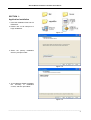
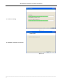
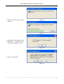
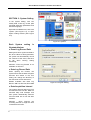
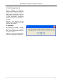
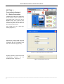
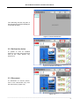
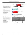
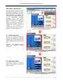
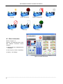
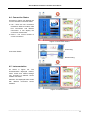
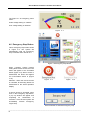
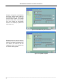
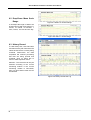
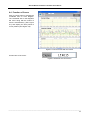
KCU-02 Monitor
Software Installation User Manual
For Windows XP and Windows 7
Headquarters : No.3, Lane 201, Chien Fu ST., Chyan Jenn Dist., Kaohsiung, TAIWAN
Tel : + 886-7-8121771
Fax : + 886-7-8121775
URL : http://www.kutai.com.tw
KCU-02 Monitor Software Installation User Manual
TABLE OF CONTENTS
Section
Section 1
Section 2
Section 3
Section 4
Section 5
Section 6
Page
Application Installation......................................................................................................... 3
System Setting .................................................................................................................... 6
Connecting to Network ........................................................................................................ 8
Monitoring.......................................................................................................................... 11
Parameter Setting ............................................................................................................. 15
Figure Recording ............................................................................................................... 18
______________________________________________________________________________________
2
KCU-02 Monitor Software Installation User Manual
SECTION 1 :
Application Installation
1. Insert the installation Disk into CD
ROM drive.
2. Double click on file setup.exe to
begin installation.
Figure 1-1
3. Select the primary installation
directory and press Next.
Figure 1-2
4. The Installation Wizard will display
the summary of installation
content, and then press Next.
Figure 1-3
______________________________________________________________________________________
3
KCU-02 Monitor Software Installation User Manual
5. Software installing
Figure 1-4
6. Installation completed. Press Next
Figure 1-5
______________________________________________________________________________________
4
KCU-02 Monitor Software Installation User Manual
7. Install Run-Time Engine Driver
software.
Figure 1-6
Figure 1-7
8. When the Run-Time Engine Driver
installation is completed, press
OK to finish installation process.
Figure 1-8
9. Click on Yes to restart.
Figure 1-9
______________________________________________________________________________________
5
KCU-02 Monitor Software Installation User Manual
SECTION 2 : System Setting
In the system setting, user can
modify data, event log, record path
and data extraction parameters and
interface language.
Open KCU-02 Monitor.exe, then click
“Option” (See Figure 2-1), to open
Option setting window (See Figure
2-2).
Figure 2-1 Options
Each System setting is
illustrated below:
● Event Log Record Path
Setting the Event Log Record Path to
file, when a Note or alarm generated,
the system will automatically record
the contents of the event, and save
to file when leaving exiting
monitoring.
Attention:Event Log Record is not
available on ATS-PLC
● Data Log Record Path
When opening the monitor, the
system will record the data at regular
intervals and stored to file, this
setting can change the directory of
the data chart record and stored.
Models available with Data Log
Record:AMF-10, GCU-100, GCU-3000
Figure 2-2 Program Setting
● Data Acquisition Interval
The system retrieves data every few
seconds and store into file. Data are
retrieved daily until 23:59pm and
then system automatically retrieves
and save data into a new file after
00:00am.
Attention : More frequent the
recording interval is, larger the size
of stored file becomes.
______________________________________________________________________________________
6
KCU-02 Monitor Software Installation User Manual
● Data Storage Interval
When connection is terminated,
system will automatically retrieve the
data and store into file. The setting of
data retrieval and saving to file can
be adjusted according to the amount
of data accumulated. Intermittent
data saving ensures preservation of
records.
Attention : The efficiency of the
system will be affected if the data
storage is set frequent.
● Language
By changing the setting of display
interface language, the language
from event log language will also
change accordingly.
Attention:System changes will take
effect after restarting the application.
______________________________________________________________________________________
7
KCU-02 Monitor Software Installation User Manual
SECTION 3 :
Connecting to Network
3.1 Device Connection
Install the KCU-02 into the expansion
slot at the back of the controller. Via
the RS485 cable, connect PC to the
RS485 device then connect from
device to KCU-02, make sure the
controller is power on and then run
file “KCU-02 Monitor.exe”.
Click “COM Port” key to enter port
setting (Figure 3-1).
Figure 3-1
Choose the correct COM port and
baud rate (the baud rate must be
consistent with the Controller) and
then click “Connect” (Figure 3-2).
Figure 3-2 Selecting COM port and Baud rate
System resumes to main screen and
automatically searches for all
installed devices. (Figure 3-3).
Figure 3-3 Searching for device
______________________________________________________________________________________
8
KCU-02 Monitor Software Installation User Manual
The searching process may take a
few seconds only and then display all
connected device(s).
Figure 3-4 Connected Device
3.2 Re-Scan for device
To update or scan for installed
device(s), go to the main screen and
click on the “Scan Device” key
(Figure 3-5)
Figure 3-5 Re-Scan for Device
3.3 Disconnect
To disconnect or remove device,
click on the “Disconnect” key from
the main screen. (Figure 3-6)
Figure 3-6
______________________________________________________________________________________
9
KCU-02 Monitor Software Installation User Manual
3.4 Online Controller Listing
After
the
system
completes
searching available controller(s), all
connected controller(s) and status
will be displayed on the top left of the
screen.
1. Thumbnail
controller.
of
the
connected
Operating
2. Controller ID and model name.
3. Indication of the current displayed
monitor of corresponding controller
on the display screen.
Warning or Shutdown
4. The 3 types of controller status
(As shown below).
Offline Status
3.5 Event Overview
When the controller sends out a Note
signal, the system will record the
corresponding controller ID, Note
message and time of occurrence in
the event log. (As shown from the
below illustration).
1. Event ID( Don’t care)
2. Description of event
3. Time of occurrence
Figure 4-9 Ensure whether the Modem is connected
______________________________________________________________________________________
10
KCU-02 Monitor Software Installation User Manual
SECTION 4 : Monitoring
KCU-02 is able to connect to several
controllers via RS485 at the same
time. By clicking on different controller
icon on the left of the screen, the
display screen will immediately open
up the corresponding controller’s
monitoring screen. The current
supportive modules include AMF-10,
AMF-11,
GCU-100,
GCU-3000,
ATS-22, ATS-33, ATS-34, ATS-PLC.
* Majority of the display content and
function of the ATS-PLC, is
synchronized with actual operation
Example:Monitoring GCU-100
Figure 4-1 Controller Monitoring Screen
4.1 Virtual Operation
On the PC monitoring screen, all
functions and lightings are virtually
displayed and synchronized with the
actual controller’ status (See Figure
4-2)
Attention : The displayed screen
varies
with
different
controller
connected.
Figure 4-2 Virtual Operation
4.2 Generator Status
As shown in Figure 4-3. There are
total of seven types of generator
operation status.
Figure 4-3 Generator Status
______________________________________________________________________________________
11
KCU-02 Monitor Software Installation User Manual
Running
Engine Shut-down
Engine Coiling down
Stop
Pre-Heat
Cranking
Idle
4.3 Other Information
Shown in Figure 4-4
Attention:The displayed frame varies
with different connected control
modules.
● Maintain (HH:mm):Maintain service
countdown.
● Run Hr.(H:m):Hours of operating.
● Battery:DC Voltage.
Figure 4-4 Other Information
______________________________________________________________________________________
12
KCU-02 Monitor Software Installation User Manual
4.4 Connection Status
As shown in Figure 4-5 displays the
current controller connection status.
● Link:There are two connection
methods to KCU-02 module, USB
Port Connection and Modem
Connection. It will display the
connection method here.
● Device : The control module of
current connection.
Figure 4-5 Connection Status
Connecting
Connection Status
Disconnecting
4.5 Instrumentation
As shown in Figure 4-6. The
instrumentation displayed content,
meter scales and related settings
vary according to different control
module connected.
Attention:The displayed frame varies
with different connected control
modules.
Figure 4-6 Instrumentation
______________________________________________________________________________________
13
KCU-02 Monitor Software Installation User Manual
The Figure 4-7 is emergency power
meter.
Under voltage setting on 180VAC
Over voltage setting on 250VAC
Figure
4-7
4.6 Emergency Stop Button
This is emergency stop button shown
in Figure 4-8. The system will
automatically send out emergency
stop command when clicked on it.
Figure 4-8 Emergency Stop Button
When controller system internal
setting allow remote access, then the
button will appear to be accessible
status (Figure 4-9); When access is
deactivated, the button will appear
as un-accessible shows in (Figure
4-10).
Figure
4-9
Figure
4-10
Attention:When the remote access
is cancelled, all executing button are
deactivated on the virtual operation
display.
If remote access is activated, when
click on the emergency stop button,
a pop up window will appear and
requesting for confirmation of
execution. Click OK and system will
immediately execute emergency
engine stop.
Ensure whether to activate emergency stop
______________________________________________________________________________________
14
KCU-02 Monitor Software Installation User Manual
The pointer will pop up when clicking
on the emergency stop button with
the controller switch OFF.
It will show OFF mode already
SECTION 5 :
Parameter Setting
From main screen, select “Controller
Setting” to open parameter setting.
Controller must be switched to OFF
status prior to programming, otherwise
system will not be permitted to enter
parameter setting screen (See Figure
5-1).
Figure 5-1
Attention : Controller must be
switched to OFF status prior to
programming, otherwise system will
not be permitted to enter parameter
setting screen (See Figure 5-2).
Figure 5-2 Can only enter setting at OFF Mode
After opening up the setting page,
and changed the parameter(s), if the
new setting differs from previous
setting, the green markers (See
Figure 5-3) on the left of the
parameter will be highlighted,
indicating has changed the setting
and waiting to be updated.
:Default setting or setting not changed.
:Parameter(s) changed and awaiting to be updated.
Figure 5-3
______________________________________________________________________________________
15
KCU-02 Monitor Software Installation User Manual
Example:In Figure 5-4, 2 parameters
have been changed, after clicking on
the Update button the system will
execute remote update. The update
process usually take a few seconds
only, some updates are immediately
effective and displayed (Reference
from Figure 4-7)
Figure 5-4 Modified Entry will be marked
Default, in anytime, user can click on
the Default key to resume to factory
settings. Any setting that differs from
the default, the markers will be
highlighted. Click on the Update key
to continue setting update.
Figure 5-5 Update Complete
______________________________________________________________________________________
16
KCU-02 Monitor Software Installation User Manual
Section 6 : Recording
Record key is available on the top
left of all monitoring screen (See
Figure 6-1). Click on the Record key
to open and view Graph Recording
(See Figure 6-2).
Figure 6-1
Once the system is online, it will
immediately begins to record data
according to user’s setting and
transforming each periodic recording
into curve chart. Each chart’s vertical
coordinates will be automatically
adjusted by system.
Figure 6-2 Graph Record Log
6.1 Show Curve Lines
The selection box enable user to
choose whether to display curves
which enables user to better observe
certain curve graphic.
: Show Curve Lines
: Hide Curve Lines
Figure 6-3 Selection box
______________________________________________________________________________________
17
KCU-02 Monitor Software Installation User Manual
6.2 Drop-Down Menu Scale
Range
Figure 6-4 Within 10 minutes Range
It can adjust the length of data to be
showed at once with scale range of 1
minute, 10 minute, 30 minutes, 1
hour, 5 hours, 10 hours and one day.
Figure 6-5 Within 1 minute Range
6.3 History Record
To view history files, click File button
and select history file of which the file
names shows the file currently being
reviewed. Furthermore, the data
acquisition will continue processing
wile files are being opened and
reviewed. Click on Close File to
return to data acquisition menu.
Attention:The record file can only be
selected according to the current
monitoring module. If the current
monitoring module is GCU-3000,
then only GCU-3000 record file can
be selected.
Figure 6-6 History File Record Log
______________________________________________________________________________________
18
KCU-02 Monitor Software Installation User Manual
6.4 Function of Cursor
Click on Cursor button to activate the
coordinate axis on each diagram.
The coordinate axis on the diagrams
will move along with the motion of
mouse simultaneously (See Figure
6-7) and display the time period of
cursor position (See Figure 6-8).
Figure 6-7 Cursor moves with the mouse
Current time of the cursor
Figure 6-8 Shower the current time
______________________________________________________________________________________
19