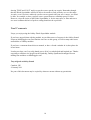
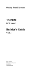
1
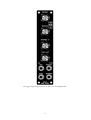
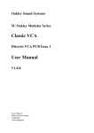
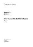
Oakley Sound Systems
5U Oakley Modular Series
Diode Superladder
Voltage Controlled Filter
Diode Superladder PCB Issue 2
User Manual
V2.0.02
Tony Allgood B.Eng PGCE
Oakley Sound Systems
CARLISLE
United Kingdom
The suggested panel layout for the 1U filter core in MOTM format.
2
The suggested panel layout for the full 3U version of the Diode Superladder module in MOTM format.
3
Introduction
This is the User Manual for the issue 2 Diode Superladder 5U module from Oakley Sound
Systems. This document contains an overview of the operation of the unit, the history of the
various board issues, and the calibration procedure
For the latest Project Builder's Guide, which contains a basic introduction to the board, a full
parts list for the components needed to populate the boards, and a list of the various
interconnections, please visit the main project webpage at:
http://www.oakleysound.com/super-d.htm
For general information regarding where to get parts and suggested part numbers please see
our useful Parts Guide at the project webpage or http://www.oakleysound.com/parts.pdf.
For general information on how to build our modules, including circuit board population,
mounting front panel components and making up board interconnects please see our generic
Construction Guide at the project webpage or http://www.oakleysound.com/construct.pdf.
4
The Oakley Diode Superladder Module
The Oakley Diode Superladder is the new version of our long running Superladder filter
design. This new version has been especially created to use diodes as the control element
instead of transistors. Earlier versions of the Superladder could be built either as transistor or
diode ladders but in 2007 a choice was made to concentrate on the transistor version only.
The Superladder was therefore optimised to sound good with transistors only.
But in the intervening years many people requested the diode option so at long last the Diode
Superladder returns. This time it has been designed from the ground up to sound good using
diodes. The circuit is considerably different from all previous designs and has its own sound.
This version features a new switch to select the maximum number of diode rungs in the ladder.
You can now chose between four and five pole filtering - with the five pole mode giving a
steeper roll off and smoother tone.
The Diode Superladder VCF features both voltage control over frequency and resonance.
Unique to any diode ladder filter is has a variable shape output. This incorporates a feature
first seen on the Oakley Orbital prototypes. A single pot allows you to vary the output from
one (or two) pole low pass to four (or five) pole low pass via band pass in the middle.
The Diode Superladder's output is what we call 'Q compensated'. This means that the output
volume will not drop significantly when you turn up the resonance pot. This design uses two
inbuilt VCAs to achieve voltage controlled resonance without the hassle. At high levels of
resonance the Diode Superladder will self-oscillate across most of the audio band and thus can
be used as a sine wave voltage controlled oscillator.
The filter core uses transistors wired as diodes which means it does not clip the signal abruptly
but saturates smoothly. This allows the Diode Superladder to sound very different depending
on the input signal level. When used with signals below 2V peak the Superladder will sound
clean and bright. However, take your signal levels above 2V peak and it will start to take on a
more strident tone particularly at higher levels of resonance. Coupled with the variable slope
control, this sensitivity to input level means the Diode Superladder can produce a wonderful
array of different tones.
The voltage controlled filter, or VCF, may be built as a 1U filter core or as a complete 3U
filter system. The 1U 'Filter Core' format is our way of handling filter modules. Although the
1U module can be used as a filter module on its own, it is expected that users will make use of
external mixers to control CV and audio levels going into the filter. In this way, you will be
able to have a collection of space saving 1U filter cores that can be used with any generic
mixer module. The Oakley Multimix is an ideal choice for a handy mixer module.
5
The Filter Core Idea
As you have read this module can be made into either a standard 2U wide module, or as a
compact 1U filter core module.
The Filter Core idea has come from the fact that many of our customers were buying different
filter types, eg. they may have an MS-20 clone, a Moog ladder filter and an SVF. Each filter
type gives a different sound so its worthwhile having a few in your modular set up. However,
each filter module also has its own input mixer for audio and an input mixer for CVs. This
adds to panel real estate and soon your modular is filling up very quickly. While this does look
very impressive, it does mean that, in many patches, you have a lot of redundant electronics in
your modular.
Step forward the 'filter core'. This is quite simply a 1U module that contains only the filter and
a few important front panel pots. All the audio and CV mixing is done externally with a
dedicated mixer module, like the Multimix. The good thing about this is that any unused filter
module is only 'wasting' 1U of panel space. So you can afford to have many different flavours
of filter without the additional cost and panel space of mixers.
However, as with all things, there are disadvantages too. The lack of inbuilt mixers mean that
you will need to get more dedicated mixer modules. But remember that these relatively cheap
mixer modules can be used for any mixing or level controlling within your modular. Thus, you
have more flexibility, at the expense of a little more patching.
The great thing about the Oakley Filter Core modules is that they will all be designed so that
they can still be used in the full format design. All the Filter Core modules will have input
summing amplifiers built onto the PCB. You won't be using these circuits in the 1U format,
but they are there if you want to go for the larger 2U or 3U designs.
6
The Superladder Legacy
The Superladder design was spawned by a project called the Walshbank. This was a complete
analogue monophonic synthesiser that incorporated a voltage controlled digital oscillator that
used an additive process to generate complex waveforms. The synthesiser also featured a
voltage controlled ADSR, a flexible analogue VCF and a fairly traditional VCA. The VCO
was a very big project on its own, so I decided to separate the VCF out and make it into a
PCB project that people could build themselves. This was the first Superladder and it was
released in late 1999.
The Superladder did various things that had not been done before to my knowledge at the
time. Firstly, it sported a one pole output, a bandpass output and a four pole output. Secondly
it could be built into either a diode ladder (like a TB303) or a transistor ladder (like a Moog).
Thirdly, it incorporated a Q compensation circuit that kept the volume of the output fairly
constant as the resonance was changed. Of course, as time passed I realised that I had not
been the first to use these ideas, but I still think it was the first time that all three had been
available in one design.
The issue 1 boards were a relative success - I managed to cover my costs, which was all that I
could ask for. However, there were some mechanical problems with fitting the board into a
MOTM panel and rack rails, so I decided to make an issue 2. This used a similar circuit, but
made it easier to wire up and made it more MOTM compatible.
Both the issue 1 and 2 boards used the 2SC1583 matched pair in the differential amplifiers and
the exponential converters. However, these were becoming harder to source so I needed to
make a new issue board. Issue 3 used the more common CA3046 NPN array and op-amps in
the differential amplifiers. It also featured a change in the way the Q-compensation worked;
the level compensation circuitry was now fitted at the input to the filter core as opposed to
after it. This was a big change in circuitry and the issue 3 boards sounded slightly different. I
would say that the new board sounded better, it was cleaner and less noisy. However, I am
waiting for the day when issue 1 Oakley boards are talked about in hushed tones as being the
best.
All the issues so far used Omeg pots. These UK made pots were quite popular at the time and
had a good reputation. However, my own experience was proving to be less than perfect. In
particular, I had one batch that was very poor, with many units having to be returned. At great
expense I began the slow roll out of a series of new designs that used the more expensive
Spectrol 248 pots. These superior pots would prove to give excellent results and, so far, have
shown good longevity.
Issue 4 Superladder PCBs and modules used Spectrol pots throughout. There were also some
subtle differences in circuitry, but not much, and mostly to allow for easier wiring.
Issue 5 was being designed as I decided to pull out of the ready made modular market in 2005.
It was laid out on my CAD system and only one board was ever made. It however sowed the
seeds for the current Transistor Superladder board, and its use of the THAT300P NPN array
proved very successful. The premise of this design was for a RoHS (lead free) compliant
Superladder. RoHS meant that we could no longer use the non compliant and now obsolete
7
CA3080 and CA3046 devices. The THAT300P fitted the job of the core array perfectly. In
fact, its actually better than the CA3046 it replaced.
The CA3080's job in the SL-4 board was to control the depth of one of the incoming CVs,
usually the envelope generator for velocity control. However, it was easier to remove the
function from the module, rather than trying to find a RoHS alternative to the CA3080. The
CV controlled EG depth was really a hangover from the Walshbank days, and our ADSR
module already had a CV controlled level built into it. This partial loss of functionality started
me thinking about the way these rather extraneous functions are handled, and so the filter core
idea was formed.
Issue 6 was therefore never formally created. Instead, the design fragmented. The next
Superladder, designed in September 2007, was labelled issue 1 Filter Core and concentrated
solely on the transistor variation of the design.
I removed the diode variation because I felt that the changes in the differential amplifiers and
the feedback paths that had so benefited the transistor version since issue 3 had not done the
same to the diode version. Simply put, I thought that since issue 3 the Diode Superladder did
not sound as good as it had. In particular, the overdrive characteristics were not as predictable
as the older designs and in issue 3 and 4 there were occasional instabilities when the resonance
and frequency CVs were changed quickly. However, it was clear after the overwhelmingly
positive response to Thomas White's popular You Tube Diode Superladder video that not
everyone agreed with me.
So, in the Summer of 2010, I redesigned the Diode Superladder. This new issue 1 was to be a
cross between the old issue 1 and issue 5. It used discrete differential amplifiers like issue 1,
but used the Q compensation circuitry of issue 5. But after building the first prototype and
testing it out I was very disappointed with the overall sound and performance of the module.
It simply did not deliver the sound I was looking for. Somewhat disgruntled I shelved the
project.
A month or so later I decided to have another bash. Rather than just tweak my previous
efforts, I started from scratch and came up with, what I hope, is a unique design. After some
exhaustive testing I finally settled on the component values that gave me the sound I wanted.
This then is the issue 2 Diode Superladder.
There are a great many differences compared to the previous versions. Q compensation is
performed in a similar fashion to that of the early Superladders, that is, it acts on the output of
the ladder core and not on the input. However, the implementation is completely different.
And instead of two differential amplifiers, there are now three, one for each of the two rung
outputs, and one for the resonance pathway. I have also added a fifth rung to the ladder
allowing five pole filtering.
I think, in issue 2 of the Diode Superladder, I have achieved a great sounding diode ladder
filter with an excellent performance and a great sound. I hope you find that it works for you
too.
8
Trimmers
There are four trimmers, or presets as we used to call them in the UK, on the PCB. You do
not need any special equipment, other than a decent voltmeter, to set these correctly.
However, a digital tuner, or a VST tuner plug in, is very useful for setting the V/octave
trimmer if you have the 3U version of the Diode Superladder.
You should use a proper trimmer tool or a fine blade jeweller's screwdriver for adjusting the
two multiturn trimmers. Vishay and others make trimmer adjusters for less than a pound. The
two 6mm round trimmers need a small electrician's screwdriver.
TUNE: This adjusts the filter’s cut-off frequency. Set this so that the filter’s FREQUENCY
pot covers your chosen range. I would normally place this in the middle position for now, that
is 10 turns or so, from one of the end points.
OFF2: Listen to the output signal and turn the FILTER SLOPE control to LOW. Set the
Resonance and Frequency pots to their mid positions. Now connect a triangle wave signal,
about 500Hz at 5V p-p, into the RESONANCE socket and turn the RESONANCE CV pot
up full. You should hear the 500Hz signal from the output but it will be very faint. Adjust
OFF2 until the sound becomes minimised. You will not get rid of it completely.
TWEAK: Adjust this trimmer so that the filter just breaks into oscillation when the resonance
pot is moved to around 80% of its maximum setting. Alter the frequency pot over its whole
range to check whether you are getting a good frequency range of oscillation. If you set
TWEAK too low, then the filter may only oscillate over a very small range.
V/OCT: This adjusts the scaling (or sensitivity) of the exponential inputs. It should stated that
you will not be able to achieve perfect keyboard tracking from the Diode Superladder. Diode
ladder filters do not behave in the same way as transistor ladders and cannot easily be made to
track to scale over a wide range.
If you have the 1U 'Filter Core' version of this module there is no need to adjust the V/OCT
trimmer. Simply leave it in its middle position. You will be controlling all CV depths with your
connected external mixer module.
For the full 3U module you have a dedicated KEY CV socket. In a perfect world V/OCT
should be adjusted so that there is an octave jump in cut-off frequency when the KEY CV
input is raised by one volt and the KEY SCALING pot is turned fully up. However, this is not
going to be the case over anything more than a couple of octaves.
Turn the key scaling and resonance pots fully up and let the filter oscillate. Then connect the
KEY CV socket to the 'keyboard CV' out of your midi-CV convertor or analogue keyboard.
Play an A on your keyboard and adjust the FREQUENCY pot so that the filter gives out a
sine wave like signal of around 880Hz. Now play the A note one octave higher than you were
pressing. By adjusting TUNE and V/OCT you should aim to get the higher A to make the
module give out 1760Hz, ie. double 880Hz. However, any change in V/OCT will also change
the lower note as well as the higher note. So you will have to move back and forth between
9
altering TUNE and V/OCT until you get the octave spread you require. Remember though
that the Diode Superladder will not be able to be made to track perfectly over a wide range.
As such, even if you have achieved a perfect octave spread with your two A notes, you won't
be able, for example, to hear a perfect octave spread from two similarly spaced C notes.
However, since the action of the Diode Superladder is, for the most part, to filter and not to
act as an oscillator this lack of perfect scaling should not be a problem.
Final Comments
I hope you enjoy using the Oakley Diode Superladder module.
If you have any problems with the module, an excellent source of support is the Oakley Sound
Forum at Muffwiggler.com. Paul Darlow and I are on this group, as well as many other users
and builders of Oakley modules.
If you have a comment about this user manual, or have a found a mistake in it, then please do
let me know.
Last but not least, can I say a big thank you to all of you who helped and inspired me. Thanks
especially to all those nice people on the Synth-diy, Oakley-Synths and Analogue Heaven
mailing lists and those at Muffwiggler.com.
Tony Allgood at Oakley Sound
Cumbria, UK
© January 2011
No part of this document may be copied by whatever means without my permission.
10